WO2017138378A1 - Terminal sans fil - Google Patents
Terminal sans fil Download PDFInfo
- Publication number
- WO2017138378A1 WO2017138378A1 PCT/JP2017/003105 JP2017003105W WO2017138378A1 WO 2017138378 A1 WO2017138378 A1 WO 2017138378A1 JP 2017003105 W JP2017003105 W JP 2017003105W WO 2017138378 A1 WO2017138378 A1 WO 2017138378A1
- Authority
- WO
- WIPO (PCT)
- Prior art keywords
- information
- wireless terminal
- side link
- control
- resource
- Prior art date
- Legal status (The legal status is an assumption and is not a legal conclusion. Google has not performed a legal analysis and makes no representation as to the accuracy of the status listed.)
- Ceased
Links
Images






Classifications
-
- H—ELECTRICITY
- H04—ELECTRIC COMMUNICATION TECHNIQUE
- H04W—WIRELESS COMMUNICATION NETWORKS
- H04W76/00—Connection management
- H04W76/10—Connection setup
- H04W76/14—Direct-mode setup
-
- H—ELECTRICITY
- H04—ELECTRIC COMMUNICATION TECHNIQUE
- H04L—TRANSMISSION OF DIGITAL INFORMATION, e.g. TELEGRAPHIC COMMUNICATION
- H04L5/00—Arrangements affording multiple use of the transmission path
-
- H—ELECTRICITY
- H04—ELECTRIC COMMUNICATION TECHNIQUE
- H04L—TRANSMISSION OF DIGITAL INFORMATION, e.g. TELEGRAPHIC COMMUNICATION
- H04L5/00—Arrangements affording multiple use of the transmission path
- H04L5/003—Arrangements for allocating sub-channels of the transmission path
- H04L5/0053—Allocation of signalling, i.e. of overhead other than pilot signals
-
- H—ELECTRICITY
- H04—ELECTRIC COMMUNICATION TECHNIQUE
- H04L—TRANSMISSION OF DIGITAL INFORMATION, e.g. TELEGRAPHIC COMMUNICATION
- H04L5/00—Arrangements affording multiple use of the transmission path
- H04L5/0091—Signalling for the administration of the divided path, e.g. signalling of configuration information
- H04L5/0094—Indication of how sub-channels of the path are allocated
-
- H—ELECTRICITY
- H04—ELECTRIC COMMUNICATION TECHNIQUE
- H04W—WIRELESS COMMUNICATION NETWORKS
- H04W16/00—Network planning, e.g. coverage or traffic planning tools; Network deployment, e.g. resource partitioning or cells structures
- H04W16/24—Cell structures
- H04W16/26—Cell enhancers or enhancement, e.g. for tunnels, building shadow
-
- H—ELECTRICITY
- H04—ELECTRIC COMMUNICATION TECHNIQUE
- H04W—WIRELESS COMMUNICATION NETWORKS
- H04W64/00—Locating users or terminals or network equipment for network management purposes, e.g. mobility management
- H04W64/003—Locating users or terminals or network equipment for network management purposes, e.g. mobility management locating network equipment
-
- H—ELECTRICITY
- H04—ELECTRIC COMMUNICATION TECHNIQUE
- H04W—WIRELESS COMMUNICATION NETWORKS
- H04W72/00—Local resource management
- H04W72/20—Control channels or signalling for resource management
-
- H—ELECTRICITY
- H04—ELECTRIC COMMUNICATION TECHNIQUE
- H04W—WIRELESS COMMUNICATION NETWORKS
- H04W76/00—Connection management
- H04W76/10—Connection setup
- H04W76/11—Allocation or use of connection identifiers
-
- H—ELECTRICITY
- H04—ELECTRIC COMMUNICATION TECHNIQUE
- H04W—WIRELESS COMMUNICATION NETWORKS
- H04W8/00—Network data management
- H04W8/005—Discovery of network devices, e.g. terminals
-
- H—ELECTRICITY
- H04—ELECTRIC COMMUNICATION TECHNIQUE
- H04W—WIRELESS COMMUNICATION NETWORKS
- H04W88/00—Devices specially adapted for wireless communication networks, e.g. terminals, base stations or access point devices
- H04W88/02—Terminal devices
- H04W88/04—Terminal devices adapted for relaying to or from another terminal or user
-
- H—ELECTRICITY
- H04—ELECTRIC COMMUNICATION TECHNIQUE
- H04W—WIRELESS COMMUNICATION NETWORKS
- H04W92/00—Interfaces specially adapted for wireless communication networks
- H04W92/16—Interfaces between hierarchically similar devices
- H04W92/18—Interfaces between hierarchically similar devices between terminal devices
-
- H—ELECTRICITY
- H04—ELECTRIC COMMUNICATION TECHNIQUE
- H04W—WIRELESS COMMUNICATION NETWORKS
- H04W76/00—Connection management
- H04W76/20—Manipulation of established connections
- H04W76/28—Discontinuous transmission [DTX]; Discontinuous reception [DRX]
Definitions
- the present disclosure relates to a wireless terminal used in a communication system.
- 3GPP 3rd Generation Partnership Project
- ProSe Proximity-based Services
- ProSe a specific wireless terminal (ProSe UE-to-Network Relay) can relay traffic between another wireless terminal (Remote UE) and the network.
- Remote UE another wireless terminal
- a wireless terminal includes a controller capable of relaying traffic between another wireless terminal and a network by a proximity service.
- the controller executes control for transmitting the first information and the second information on the side link.
- the first information is used to specify the position of the radio resource where the second information is arranged.
- the second information is used to specify the location of a radio resource for requesting relaying by the proximity service.
- a wireless terminal receives first information and second information on a side link from another wireless terminal capable of relaying traffic between the wireless terminal and a network by a proximity service.
- the control part which performs control to perform is provided.
- the first information is used to specify the position of the radio resource where the second information is arranged.
- the second information is used to specify the location of a radio resource for requesting relaying by the proximity service.
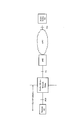
- FIG. 1 is a diagram illustrating a configuration of an LTE system.
- FIG. 2 is a protocol stack diagram of a radio interface in the LTE system.
- FIG. 3 is a configuration diagram of a radio frame used in the LTE system.
- FIG. 4 is a diagram for explaining relaying by the proximity service.
- FIG. 5 is a block diagram of the UE 100.
- FIG. 6 is a block diagram of the eNB 200.
- FIG. 7 is a sequence diagram for explaining the outline of the restart procedure.
- FIG. 8 is a diagram (part 1) for explaining the operation according to the embodiment.
- FIG. 9 is a diagram (part 2) for explaining the operation according to the embodiment.
- FIG. 10 is a diagram (No. 3) for explaining the operation according to the embodiment.
- FIG. 11 is a diagram (No.
- FIG. 12 is a diagram (No. 5) for explaining the operation according to the embodiment.
- FIG. 13 is a diagram (No. 6) for explaining the operation according to the embodiment.
- FIG. 14 is a sequence diagram for explaining the first modification.
- FIG. 15 is a sequence diagram for explaining the second modification.
- FIG. 16 is a sequence diagram for explaining the third modification.
- a wireless terminal includes a controller capable of relaying traffic between another wireless terminal and a network by a proximity service.
- the controller executes control for transmitting the first information and the second information on the side link.
- the first information is used to specify the position of the radio resource where the second information is arranged.
- the second information is used to specify the location of a radio resource for requesting relaying by the proximity service.
- the controller may execute control to receive the relay request transmitted using the radio resource from the other radio terminal.
- the controller may execute control to transmit information indicating that the relay is desired to the base station in response to reception of the relay request.
- the wireless resource may include a plurality of different small resources. Each of the plurality of small resources may be associated with a different temporary identifier.
- the relay request may include a temporary identifier associated with the small resource used to transmit the relay request.
- the controller may execute control for transmitting a response to the relay request to the other wireless terminal. The response may include the temporary identifier included in the relay request.
- the controller may execute control to transmit a response to the relay request to the other wireless terminal.
- the response may include information for adjusting a transmission timing from the other wireless terminal to the wireless terminal.
- the controller may execute control to receive third information on the side link from the other wireless terminal or base station before transmitting the first information.
- the controller may start control for transmitting the first information in response to reception of the third information.
- the controller may be individually assigned from the base station the individual resources used in the side link.
- the controller may share the dedicated resource with the other wireless terminal.
- a plurality of control areas used for transmission of control information may be arranged in the time direction.
- the control information may be used for specifying a position of a radio resource where user data transmitted in a side link is arranged.
- the controller may select a control area used for transmission of control information from the plurality of control areas in accordance with a side link DRX (Discontinuous Reception) operation of the other wireless terminal.
- the side link DRX operation may be an operation in which the other radio terminal discontinuously monitors the plurality of control areas.
- the controller may execute control for transmitting power control information to the other wireless terminal.
- the power control information may include parameter information for controlling transmission power of a side link signal from the other radio terminal to the radio terminal.
- the parameter information may be determined according to reception power of a side link signal from the wireless terminal to the other wireless terminal.
- the controller may execute control for transmitting power control information to the other wireless terminal.
- the power control information may include command information for controlling transmission power of a side link signal from the other wireless terminal to the wireless terminal.
- the command information may be determined according to received power of the side link signal.
- a wireless terminal receives first information and second information on a side link from another wireless terminal capable of relaying traffic between the wireless terminal and a network by a proximity service.
- the control part which performs control to perform is provided.
- the first information is used to specify the position of the radio resource where the second information is arranged.
- the second information is used to specify the location of a radio resource for requesting relaying by the proximity service.
- the controller may execute control to transmit the relay request to the other wireless terminal using the wireless resource.
- the wireless resource may include a plurality of different small resources. Each of the plurality of small resources may be associated with a different temporary identifier.
- the controller may include a temporary identifier associated with a small resource used for transmission of the relay request in the relay request.
- the controller may execute control for receiving a response to the relay request from the other wireless terminal.
- the response may include the temporary identifier included in the relay request.
- the controller may execute control for receiving a response to the relay request from the other wireless terminal.
- the response may include information for adjusting a transmission timing from the wireless terminal to the other wireless terminal.
- the controller may execute control for transmitting third information on the side link before receiving the first information.
- the controller may receive the first information from the other wireless terminal that has received the third information.
- the controller may share an individual resource used in the side link with the other wireless terminal.
- the dedicated resource may be a radio resource individually allocated from a base station to the other radio terminal.
- a plurality of control areas used for transmission of control information may be arranged in the time direction.
- the control information may be used for specifying a position of a radio resource where user data transmitted in a side link is arranged.
- the controller may execute a side link DRX (Discontinuous Reception) operation that discontinuously monitors the plurality of control regions.
- the controller may execute control for receiving power control information from the other wireless terminal.
- the power control information may include parameter information for controlling transmission power of a side link signal from the wireless terminal to the other wireless terminal.
- the parameter information may be determined according to reception power of a side link signal from the other wireless terminal to the wireless terminal.
- the controller may execute control for receiving power control information from the other wireless terminal.
- the power control information may include command information for controlling transmission power of a side link signal from the wireless terminal to the other wireless terminal.
- the command information may be determined according to received power of the side link signal.
- FIG. 1 is a diagram illustrating a configuration of an LTE system.
- the LTE system includes a UE (User Equipment) 100, an E-UTRAN (Evolved Universal Terrestrial Radio Access Network) 10, and an EPC (Evolved Packet Core) 20.
- UE User Equipment
- E-UTRAN Evolved Universal Terrestrial Radio Access Network
- EPC Evolved Packet Core
- the UE 100 corresponds to a wireless terminal.
- the UE 100 is a mobile communication device.
- UE100 performs radio
- the configuration of the UE 100 will be described later.
- the E-UTRAN 10 corresponds to a radio access network.
- the E-UTRAN 10 includes an eNB 200 (evolved Node-B).
- the eNB 200 corresponds to a base station.
- the eNB 200 is connected to each other via the X2 interface. The configuration of the eNB 200 will be described later.
- ENB 200 manages one or a plurality of cells.
- eNB200 performs radio
- the eNB 200 has a radio resource management (RRM) function, a routing function of user data (hereinafter also referred to as “data”), a measurement control function for mobility control / scheduling, and the like.
- RRM radio resource management
- Cell is used as a term indicating a minimum unit of a wireless communication area. “Cell” may also be used as a term indicating a function of performing wireless communication with the UE 100.
- the EPC 20 corresponds to a core network.
- the EPC 20 may form a network together with the E-UTRAN 10.
- the EPC 20 includes an MME (Mobility Management Entity) 300, an SGW (Serving Gateway) 400, and a PGW (Packet Data Network Gateway) 500.
- MME Mobility Management Entity
- SGW Serving Gateway
- PGW Packet Data Network Gateway
- the MME 300 performs various mobility controls for the UE 100, for example.
- the SGW 400 performs data transfer control.
- MME300 and SGW400 are connected with eNB200 via a S1 interface.
- the PGW 500 performs control to relay user data from an external network (and to the external network).
- Server 600 is provided in the external network.
- Server 600 is, for example, a ProSe application server (ProSe Application Server).
- Server 400 (ProSe application server) manages an identifier used in ProSe.
- the Server 600 may have a ProSe function.
- the ProSe function is a logical function used for network-related operations necessary for ProSe.
- the ProSe function plays a different role for each feature of ProSe.
- the server 400 may be a network device having only the ProSe function.
- FIG. 2 is a protocol stack diagram of a radio interface in the LTE system. As shown in FIG. 2, the radio interface protocol is divided into the first to third layers of the OSI reference model.
- the first layer is a physical (PHY) layer.
- the second layer includes a MAC (Medium Access Control) layer, an RLC (Radio Link Control) layer, and a PDCP (Packet Data Convergence Protocol) layer.
- the third layer includes an RRC (Radio Resource Control) layer.
- the physical layer performs encoding / decoding, modulation / demodulation, antenna mapping / demapping, and resource mapping / demapping.
- Data and control signals are transmitted between the physical layer of the UE 100 and the physical layer of the eNB 200 via a physical channel.
- the MAC layer performs data priority control, retransmission processing by hybrid ARQ (HARQ), random access procedure, and the like. Data and control signals are transmitted between the MAC layer of the UE 100 and the MAC layer of the eNB 200 via a transport channel.
- the MAC layer of the eNB 200 includes a scheduler (MAC scheduler). The scheduler determines the uplink / downlink transport format (transport block size, modulation / coding scheme (MCS)) and the resource blocks allocated to the UE 100.
- MCS modulation / coding scheme
- the RLC layer transmits data to the RLC layer on the receiving side using the functions of the MAC layer and the physical layer. Data and control signals are transmitted between the RLC layer of the UE 100 and the RLC layer of the eNB 200 via a logical channel.
- the PDCP layer performs header compression / decompression and encryption / decryption.
- the RRC layer is defined only in the control plane that handles control signals. Messages for various settings (RRC messages) are transmitted between the RRC layer of the UE 100 and the RRC layer of the eNB 200.
- the RRC layer controls the logical channel, the transport channel, and the physical channel according to establishment, re-establishment, and release of the radio bearer.
- RRC Radio Resource Control
- a NAS (Non-Access Stratum) layer located above the RRC layer performs, for example, session management and mobility management.
- FIG. 3 is a configuration diagram of a radio frame used in the LTE system.
- OFDMA Orthogonal Frequency Division Multiple Access
- SCFDMA Single Carrier Frequency Division Multiple Access
- the radio frame is composed of 10 subframes arranged in the time direction.
- Each subframe is composed of two slots arranged in the time direction.
- the length of each subframe is 1 ms.
- the length of each slot is 0.5 ms.
- Each subframe includes a plurality of resource blocks (RB: Resource Block) in the frequency direction.
- Each subframe includes a plurality of symbols in the time direction.
- Each resource block includes a plurality of subcarriers in the frequency direction.
- One resource element (RE) is configured by one symbol and one subcarrier.
- a radio resource (time / frequency resource) is allocated to the UE 100.
- radio resources frequency resources
- radio resources are configured by resource blocks.
- radio resources (time resources) are configured by subframes (or slots).
- the section of the first several symbols of each subframe is an area that can be used as a physical downlink control channel (PDCCH: Physical Downlink. Control Channel) for transmitting a downlink control signal.
- the remaining part of each subframe is an area that can be used as a physical downlink shared channel (PDSCH) for transmitting downlink data.
- PDCH Physical Downlink control channel
- PDSCH physical downlink shared channel
- both ends in the frequency direction in each subframe are areas that can be used as physical uplink control channels (PUCCH: Physical Uplink Control Channels) for transmitting uplink control signals.
- PUCCH Physical Uplink Control Channels
- the remaining part of each subframe is an area that can be used as a physical uplink shared channel (PUSCH) for transmitting uplink data.
- PUSCH physical uplink shared channel
- a proximity service is a service that can be provided by the 3GPP system based on UEs that are in proximity to each other.
- ProSe various radio signals are transmitted / received via a direct radio link between nodes (for example, between UEs) without going through the eNB 200.
- a direct radio link in ProSe is referred to as a “side link”.
- the side link may be an interface for side link communication and side link discovery (for example, an interface between the UE and the UE).
- the side link communication is a function (AS functionality) that enables ProSe direct communication (hereinafter referred to as “direct communication” as appropriate).
- Side link discovery is a function (AS functionality) that enables ProSe direct discovery (hereinafter referred to as “direct discovery” as appropriate).
- the side link corresponds to the PC5 interface.
- the PC 5 is a reference point between ProSe-usable UEs (ProSe-enabled UEs) used for the control plane and user plane for ProSe direct discovery, ProSe direct communication and ProSe UE-to-network relay.
- ProSe-usable UEs ProSe-enabled UEs
- Direct discovery is a mode in which a partner is searched by directly transmitting a discovery message (discovery signal) that does not designate a specific destination between UEs.
- the direct discovery is a procedure for discovering another UE in the vicinity of the UE using a direct radio signal in E-UTRA (Evolved Universal Terrestrial Radio Access) via the PC 5.
- the direct discovery is a procedure adopted by the UE 100 capable of executing the proximity service in order to discover other UEs 100 capable of executing the proximity service using only the capability of the two UEs 100 with the E-UTRA technology.
- Direct discovery is supported only when UE 100 is served by E-UTRAN (eNB 200 (cell)). When the UE 100 is connected to the cell (eNB 200) or located in the cell, the UE 100 can be provided with service by the E-UTRAN.
- Type 1 There are “type 1” and “type 2 (type 2B)” as resource allocation types for transmission (announcement) of discovery messages (discovery signals).
- Type 1 the UE 100 selects a radio resource.
- type 2 type 2B
- the eNB 200 allocates radio resources to the UE 100.
- the “Sidelink Direct Discovery” protocol stack includes a physical (PHY) layer, a MAC layer, and a ProSe protocol.
- a discovery signal is transmitted between a physical layer of UE (A) and a physical layer of UE (B) via a physical channel called a physical side link discovery channel (PSDCH).
- a discovery signal is transmitted between the MAC layer of UE (A) and the MAC layer of UE (B) via a transport channel called a side link discovery channel (SL-DCH).
- Direct communication is a mode in which data is directly transmitted between UEs by specifying a specific destination (destination group).
- Direct communication is communication between two or more UEs capable of performing proximity services by user plane transmission using E-UTRA technology via a path that does not pass through any network node.
- the direct communication resource allocation types include “mode 1” and “mode 2”.
- mode 1 the eNB 200 designates radio resources for direct communication.
- mode 2 the UE 100 selects a radio resource for direct communication.
- the direct communication protocol stack includes a physical (PHY) layer, a MAC layer, an RLC layer, and a PDCP layer.
- a control signal is transmitted via the physical side link control channel (PSCCH), and data is transmitted via the physical side link shared channel (PSSCH). Is transmitted.
- a synchronization signal or the like may be transmitted through a physical side link broadcast channel (PSBCH).
- PSBCH physical side link broadcast channel
- Data is transmitted between the MAC layer of UE (A) and the MAC layer of UE (B) via a transport channel called a side link shared channel (SL-SCH).
- SL-SCH side link shared channel
- STCH side link traffic channel
- FIG. 4 is a diagram for explaining UE-to-network relay according to the embodiment.
- a remote UE is, for example, a UE located outside the network range (Outof-Network). That is, the remote UE is located outside the cell coverage. The remote UE may be located within the coverage of the cell. Therefore, the remote UE is a UE 100 that is not directly served by the E-UTRAN 10 (a UE 100 that is not served by the E-UTRAN 10).
- the remote UE 100 can communicate with a packet data network (PDN: Packet Data Network) via a relay UE described later.
- PDN Packet Data Network
- the remote UE may be a public safety (UE) for public safety (ProSe-enabled Public Safe UE).
- ProSe-enabled Public Safety UE is configured so that HPLMN permits use for public safety.
- ProSe-enabled Public Safety UE can use the neighborhood service and supports the procedure in the neighborhood service and specific capabilities for public safety.
- “ProSe-enabled Public Safe UE” transmits information for public safety through a neighborhood service.
- the information for public safety is, for example, information on disasters (earthquakes, fires, etc.), information used for fire fighting personnel or police personnel, and the like.
- the remote UE is provided with a ProSe relay service from the relay UE, as will be described later.
- UE-to-network relay is executed between a remote UE provided with the ProSe relay service and a relay UE provided with the ProSe relay service.
- Relay UE Provides ProSe relay service for remote UEs.
- the relay UE provides service continuity of communication with the packet data network for the remote UE. Therefore, the relay UE relays data (unicast traffic) between the remote UE and the network.
- the relay UE relays data (traffic) of the remote UE by a proximity service (direct communication).
- the relay UE relays data (uplink traffic) received from the remote UE via the PC5 interface to the eNB 200 via the Uu interface (LTE-Uu) or the Un interface (LTE-Un).
- the relay UE relays data (downlink traffic) received from the eNB 200 via the Uu interface or Un interface to the remote UE via the PC5 interface.
- the relay UE is located only in the network (within the coverage of the cell).
- the relay UE can provide a comprehensive function capable of relaying any type of traffic related to communication for public safety.
- Relay UE and remote UE can transmit data and control signals between physical layers.
- the relay UE and the remote UE can transmit data and control signals between the MAC layer, the RLC layer, and the PDCP layer.
- the relay UE may have an IP relay (IP-Relay) layer as an upper layer of the PDCP layer.
- the remote UE may have an IP layer as an upper layer of the PDCP layer.
- the relay UE and the remote UE can transmit data and control signals between the IP relay layer and the IP layer.
- the relay UE can transmit data between the IP relay layer and the IP layer of the IP-GW 350.
- the relay UE can transmit data (traffic) to the remote UE using broadcast in the AS layer (Access Stratum).
- the relay UE may transmit data to the remote UE using unicast in the AS layer.
- feedback in the AS layer may not be performed between the relay UE and the remote UE.
- feedback in the NAS layer Non Access Stratum
- UE-to-network relay is performed using unicast, feedback in the AS layer may be performed.
- the UE 100 (wireless terminal)
- UE100 which concerns on embodiment contains (A) UE which has a cellular communication function, and (B) UE which does not have a cellular communication function.
- a UE that does not have a cellular communication function has a side link function.
- a UE that does not have a cellular communication function may be referred to as an SL-UE.
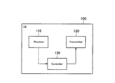
- FIG. 5 is a block diagram of the UE 100. As illustrated in FIG. 5, the UE 100 includes a receiver (receiver) 110, a transmitter (transmitter) 120, and a controller (controller) 130.
- the receiver 110 and the transmitter 120 may be an integrated transceiver (transmission / reception unit).
- Receiver 110, transmitter 120, and controller 130 are used to perform cellular communication and side link operations.
- the receiver 110 performs various types of reception under the control of the controller 130.
- the receiver 110 includes an antenna.
- the receiver 110 converts a radio signal received by the antenna into a baseband signal (received signal).
- the receiver 110 outputs a baseband signal to the controller 130.
- the transmitter 120 performs various transmissions under the control of the controller 130.
- the transmitter 120 includes an antenna.
- the transmitter 120 converts the baseband signal (transmission signal) output from the controller 130 into a radio signal.
- the transmitter 130 transmits a radio signal from the antenna.
- the controller 130 performs various controls in the UE 100.
- the controller 130 includes a processor and a memory.
- the memory stores a program executed by the processor and information used for processing by the processor.
- the processor includes a baseband processor and a CPU (Central Processing Unit).
- the baseband processor performs, for example, modulation / demodulation and encoding / decoding of a baseband signal.
- the CPU performs various processes by executing programs stored in the memory.
- the processor may include a codec that performs encoding / decoding of an audio / video signal.
- the processor executes various processes described later and various communication protocols described above.
- the UE 100 may include a GNSS receiver.
- the GNSS receiver can receive a GNSS signal in order to obtain location information indicating the geographical location of the UE 100.
- the GNSS receiver outputs a GNSS signal to the controller 130.
- UE100 may have a GPS function for acquiring position information of UE100.
- the SL-UE 100 that does not have a cellular communication function will be described. Similar to the UE 100 described above, the SL-UE 100 includes a receiver 110, a transmitter 120, and a controller 130.
- the receiver 110, the transmitter 120, and the controller 130 provided in the SL-UE 100 can perform only a side link operation, and the SL-UE 100 does not include a receiver and a transmitter that can perform cellular communication. Therefore, the receiver 110, the transmitter 120, and the controller 130 included in the SL-UE 100 perform the same operation as described above, but the “radio signal” is a radio signal in the side link. In other respects, the receiver 110, the transmitter 120, and the controller 130 perform the same operations as described above.
- the SL-UE 100 is, for example, a communication device (wearable UE) that a user can wear.
- the SL-UE 100 may be a communication device for machine type communication (MTC: Machine Type Communication) that is communication without human intervention.
- MTC Machine Type Communication
- the SL-UE 100 may not require the installation of an existing SIM (Subscriber Identity Module Card).
- the SLUE 100 may be capable of mounting an SL-UE SIM (D2D SIM).
- the SL-UE 100 Since the SL-UE 100 does not require an existing SIM to be mounted, the SL-UE 100 does not hold information (Pre-configured parameters) set via the network from the ProSe function.
- a process executed by at least one of the receiver 110, the transmitter 120, and the controller 130 included in the UE 100 will be described as a process (operation) executed by the UE 100 for convenience.
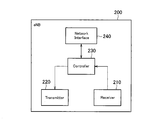
- FIG. 6 is a block diagram of the eNB 200. As illustrated in FIG. 6, the eNB 200 includes a receiver (reception unit) 210, a transmitter (transmission unit) 220, a controller (control unit) 230, and a network interface 240.
- the transmitter 210 and the receiver 220 may be an integrated transceiver (transmission / reception unit).
- the receiver 210 performs various types of reception under the control of the controller 230.
- the receiver 210 includes an antenna.
- the receiver 210 converts a radio signal received by the antenna into a baseband signal (received signal).
- the receiver 210 outputs a baseband signal to the controller 230.
- the transmitter 220 performs various transmissions under the control of the controller 230.
- the transmitter 220 includes an antenna.
- the transmitter 220 converts the baseband signal (transmission signal) output from the controller 230 into a radio signal.
- the transmitter 220 transmits a radio signal from the antenna.
- the controller 230 performs various controls in the eNB 200.
- the controller 230 includes a processor and a memory.
- the memory stores a program executed by the processor and information used for processing by the processor.
- the processor includes a baseband processor and a CPU.
- the baseband processor performs, for example, modulation / demodulation and encoding / decoding of a baseband signal.
- the CPU performs various processes by executing programs stored in the memory.
- the processor executes various processes described later and various communication protocols described above.
- the network interface 240 is connected to the neighboring eNB 200 via the X2 interface.
- the network interface 240 is connected to the MME 300 and the SGW 400 via the S1 interface.
- the network interface 240 is used for communication performed on the X2 interface and communication performed on the S1 interface, for example.
- a process executed by at least one of the transmitter 210, the receiver 220, the controller 230, and the network interface 240 included in the eNB 200 will be described as a process (operation) executed by the eNB 200 for convenience.
- FIG. 7 is a sequence diagram for explaining the operation according to the embodiment.
- 8 to 13 are diagrams for explaining the operation according to the embodiment.
- UE 100-1 has a cellular communication function and a side link function. That is, the UE 100-1 can execute the UE-to-network relay operation.
- UE 100-1 is located in a cell managed by eNB 200.
- UE 100-1 is in the RRC connection state. Alternatively, the UE 100-1 may be in the RRC idle state.
- the UE 100-2 does not have a cellular communication function but has a side link function.
- the UE 100-2 is the SL-UE 100.
- UE 100-2 is a remote UE.
- the radio signal in the side link is transmitted / received using a licensed band and / or an unlicensed band. Therefore, UE 100-1 and UE 100-2 may be UEs that support only the licensed band. UE 100-1 and UE 100-2 may be UEs that support only unlicensed bands. UE 100-1 and UE 100-2 may be UEs that support both licensed and unlicensed bands.
- the licensed band is a frequency band that requires a license.
- the licensed band is an unlicensed band used for cellular communication and is a license-free frequency band.
- step S101 the UE 100-1 transmits a master information block SL (MIB-SL) message on the side link.
- the UE 100-1 may transmit a synchronization signal (SLSS) together with the MIB-SL message in the side link.
- MIB-SL master information block SL
- SLSS synchronization signal
- the UE 100-1 may transmit the MIB-SL message (and SLSS) periodically or aperiodically. For example, the UE 100-1 may transmit the MIB-SL message with a constant multiple of the minimum period X [ms] of the MIB-SL message (and SLSS) defined in advance. For example, when there are a plurality of transmission opportunities in the predetermined period Y [ms], the UE 100-1 may randomly select an opportunity to transmit the MIB-SL message from the plurality of transmission opportunities. .
- the UE 100-1 may transmit the MIB-SL message regardless of whether or not a remote UE exists in the vicinity.
- the transmission cycle of the MIB-SL message before discovering the remote UE may be longer than the transmission cycle of the MIB-SL message after discovering the remote UE.
- a plurality of periods may be set by the eNB 200 for the MIB-SL message (and SLSS).
- the eNB 200 may transmit the setting information about the MIB-SL message (and SLSS) by dedicated signaling.
- the eNB 200 may transmit the setting information by common signaling (for example, SIB (System Information Block)).
- the MIB-SL message is used to specify the position of a radio resource where a system information block SL (SIB-SL) described later is arranged.
- SIB-SL system information block SL
- the MIB-SL message may include, for example, information for specifying the position of the radio resource where the SIB-SL is arranged.
- the MIB-SL message may include information specifying a time position (for example, a subframe) of a radio resource where the SIB-SL is arranged.
- the MIB-SL message may include information specifying the frequency position of the radio resource where the SIB-SL is arranged.
- DirectFrameNumber indicates a frame number in which SLSS and SL-BCH (Sidelink Broadcast Channel) are transmitted.
- Direct SubframeNumber indicates a subframe in the frame corresponding to “directFrameNumber”.
- Sl-Bandwidth is a frequency bandwidth setting parameter used for the side link.
- the position of the radio resource where the SIB-SL is arranged may be specified by the position of the MIB-SL message (that is, the position of the radio resource where the MIB-SL message is arranged).
- the frequency band in which the MIB-SL message is transmitted may be the same as the frequency band in which the SIB-SL is transmitted.
- the SIB-SL may be located after a predetermined time has elapsed from the time position of the MIB-SL message.
- the MIB-SL message may include a parameter nPSCCH.
- the parameter nPSCCH is used to specify a radio resource (PSCCH resource) to which control information is transmitted.
- the control information is information for indicating (designating) a radio resource (PSSCH resource) to which SIB-SL (specifically, SIB-SL (SA) described later) is transmitted.
- the UE 100-1 may start transmitting a MIB-SL message (and SLSS) based on an operation from the user.
- the UE 100-1 may transmit the MIB-SL message when the function of the relay UE is in an ON state by a user operation.
- the UE 100-1 may stop the transmission of the MIB-SL message when the function of the relay UE is in an OFF state by a user operation.
- SLSS is a side link synchronization signal (SLSS) transmitted via PSBCH.
- the SLSS includes a primary side link synchronization signal (PSSS: Primary Side Synchronization Signal) and a secondary side link synchronization signal (SSSS: Secondary Side Link Synchronization Signal).
- PSSS Primary Side Synchronization Signal
- SSSS Secondary Side Link Synchronization Signal
- step S102 the UE 100-2 that has received the MIB-SL message starts monitoring the SIB-SL.
- the UE 100-2 uses the MIB-SL message to specify the position of the radio resource where the SIB-SL is arranged.
- the UE 100-2 may specify the position of the radio resource where the SIB-SL is arranged based on the information included in the MIB-SL message.
- the UE 100-2 may specify the position of the radio resource where the SIB-SL is arranged by the position of the MIB-SL message (time position and / or frequency position).
- the UE 100-2 may specify the position of the radio resource where the SIB-SL is arranged using the parameter nPSCCH.
- UE 100-1 identifies a PSCCH resource used for transmission of control information using parameter nPSCCH.
- the UE 100-2 acquires control information by monitoring the specified PSSCH resource.
- the UE 100-2 can specify the position of the radio resource where the SIB-SL (SA) is arranged using the acquired control information (see FIG. 8).
- the SIB-SL (SA) is information for specifying the position of the radio resource where the SIB-SL (Data) is arranged.
- UE 100-2 monitors the position of the radio resource where the specified SIB-SL is placed.
- step S103 the UE 100-1 transmits SIB-SL (system information block SL message) on the side link.
- SIB-SL system information block SL message
- the UE 100-1 transmits the SIB-SL, for example, via SBCCH (Sidelink Broadcast Control Channel).
- SIB-SL is composed of SIB-SL (SA) and SIB-SL (Data).
- SA SIB-SL
- Data SIB-SL
- the MIB-SL message is used to specify the position of the radio resource where at least the SIB-SL (SA) is arranged.
- the SIB-SL (SA) is used to specify the position of the radio resource where the SIB-SL (Data) is arranged.
- the SIB-SL (SA) may include information (scheduling assignment: SA (Scheduling Assignment)) for specifying the position of the radio resource in which the SIB-SL (Data) is arranged.
- the SIB-SL (SA) may include information specifying a time position and / or a frequency position of a radio resource where the SIB-SL (Data) is arranged.
- the position of the radio resource where the SIB-SL (Data) is arranged may be specified by the position of the radio resource where the SIB-SL (SA) is arranged.
- the frequency position of SIB-SL (SA) may correspond to the frequency position of SIB-SL (Data).
- the SIB-SL (Data) may be positioned after a predetermined time has elapsed from the time position of the SIB-SL (SA).
- SIB-SL includes radio resources for requesting relaying by a nearby service.
- the radio resource may be a resource pool (s).
- the radio resource is a radio resource (DiscTxNormalResource: resource pool for side link discovery) used for discovery in the side link or a radio resource (CommTxNormalResource: resource pool for side link communication) used for communication in the side link.
- the wireless resource includes a plurality of different small resources.
- the small resources may be resources having different time / frequency positions.
- the small resource is, for example, (multiple) resource blocks (RB) selected from the (multiple) resource pool.
- RB resource blocks
- Each of the plurality of small resources may be associated with a different temporary identifier (Temporary ID).
- the SIB-SL may include power information indicating the transmission power of the side link signal (for example, at least one of the SSSS, MIB-SL, and SIB-SL) from the UE 100-1 that is the transmission source. Good.
- the UE 100-2 may calculate the path loss based on the power information and the reception level of the side link signal from the UE 100-1.
- the UE 100-2 may adjust the transmission power based on the path loss.
- the UE 100-2 may use the reception level (reception strength (S-RSRP) and reception quality (S-RSRQ)) of the reference signal in the RB (resource block) in which the PSBCH is transmitted.
- the UE 100-2 may use the reception level (reception strength (SD-RSRP) and reception quality (SD-RSRQ)) of the reference signal in the RB through which the PSDCH is transmitted.
- the UE 100-2 specifies the position of the radio resource where the SIB-SL (Data) is arranged by the SIB-SL (SA). By receiving the SIB-SL (Data), the UE 100-2 can know the radio resource for requesting the relay by the proximity service.
- the UE 100-2 may select a radio resource (small resource) to be used from among the radio resources.
- the UE 100-2 may select a small resource at random.
- the UE 100-2 may select a small resource based on the parameter nPSDCH.
- the parameter nPSDCH is a parameter used for the UE 100-2 to uniquely select a radio resource in the resource pool.
- Radio resource pool a radio resource (resource pool) (Pre-config.) From a network (e.g., eNB 200 or ProSe application server) while in the cell. It can be acquired in advance. Radio resource settings may be stored in a SIM attached to an existing UE. Therefore, an existing UE can designate a radio resource (resource pool) to be used for a relay request even in a MIB-SL message with a limited capacity.
- the UE 100-2 that cannot execute the cellular communication cannot hold the radio resource setting in advance if the existing SIM is not installed. Therefore, the UE 100-2 does not know the radio resource (resource pool) to be used even when the radio resource is designated by the MIB-SL message.
- the MIB-SL message is transmitted together with the SLSS, basically, UEs that are not synchronized are targeted for reception. For this reason, even if information indicating the radio resource (resource pool) used for the relay request is included in the MIB-SL message by expanding the capacity of the MIB-SL message, the UE that is not synchronized has a large capacity. May not receive all of the MIB-SL messages. Therefore, there is a possibility that the UE 100-2 cannot make a relay request until the next MIB-SL message is received. The extension of the MIBSL message can cause interference.
- the UE 100-2 can specify the position of the radio resource where the SIB-SL is arranged by the MIB-SL message.
- the position of the radio resource where the SIB-SL is arranged is specified by the position of the MIB-SL message, there is no problem even if the capacity of the MIB-SL message is limited.
- the existing MIB-SL message can include information for specifying the position of the radio resource where the SIB-SL is arranged. Therefore, the UE 100-2 can know the radio resource for requesting the relay by the proximity service by the existing MIB-SL message.
- the UE 100-2 can receive the SIB-SL after synchronizing with the source UE 100-1 by SLSS, even when the information amount of the SIB-SL is large, the UE 100-2 receives all of the SIB-SL more reliably. Is possible.
- the UE 100-2 requests the UE 100-1 to relay by the proximity service.
- the UE 100-2 uses the radio resource (small resource) included in the SIB-SL (Data) to request relay to the UE 100-1 on the side link.
- UE 100-2 transmits a message (relay request: first message) for requesting relay to UE 100-1.
- the UE 100-2 may transmit a discovery message as a relay request using 2 RB radio resources.
- the UE 100-2 may request the UE 100-1 to relay by a discovery message (Discovery announcements) using a discovery radio resource (DiscTxNormalResource).
- a discovery message (Discovery announcements) using a discovery radio resource (DiscTxNormalResource).
- DiscTxNormalResource a discovery radio resource
- the relay request may include temporary identifiers associated with a plurality of small resources. That is, the UE 100-2 may include a temporary identifier in the relay request.
- the UE 100-2 may randomly select the content of the message for the relay request from a predetermined range. For example, when using the discovery message, the UE 100-2 randomly selects the content of the message from a plurality of pattern values (for example, a value “2232”). The UE 100-2 transmits a discovery message including the selected pattern value to the UE 100-1 as a relay request.
- the contents of the message may be different signal sequences.
- the signal sequence is a signal sequence (preamble sequence) used when a relay by a nearby service is requested.
- the relay UE UE 100-1 can grasp the plurality of relaying requests.
- the UE 100-1 may indirectly grasp the parameter nPSDCH used by the UE 100-2 from the position of the resource (position where the resource is arranged). For example, the UE 100-1 monitors the resources in the resource pool for the relay request. The UE 100-1 determines the parameter nPSDCH used by the UE 100-2 from the position of the resource (that is, the resource where the CRC (Cyclic Redundancy Check) has been successfully performed) that the signal has been successfully received. I can know.
- CRC Cyclic Redundancy Check
- the UE 100-1 receives from UE 100-2 a relay request transmitted using radio resources (small resources) included in SIB-SL (Data).
- the UE 100-1 stores the content included in the relay request.
- the UE 100-1 stores the parameter nPSDCH and a temporary identifier.
- the UE 100-1 may store a propagation delay (delay time) between the UE 100-1 and the UE 100-2.
- the UE 100-1 can estimate the propagation delay (delay time) by the following method.
- the UE 100-2 synchronizes with the synchronization signal (SLSS) from the UE 100-1.
- SLSS synchronization signal
- a synchronization shift (delay time ⁇ ) occurs between the UE 100-1 and the UE 100-2.
- the UE 100-2 that does not have the cellular communication function does not have the timing reference, and therefore cannot recognize the synchronization shift. Therefore, the UE 100-2 transmits the relay request after the delay time ⁇ from the reference of the UE 100-1. Further, the UE 100-1 receives the relay request after the delay time ⁇ depending on the distance between the UE 100-1 and the UE 100-2.
- the difference (propagation delay) between the timing when the UE 100-1 receives the relay request and the reference timing of the UE 100-1 is 2 ⁇ .
- the UE 100-1 may specify a small resource by the parameter nPSDCH and / or a temporary identifier.
- step S105 the UE 100-2 starts monitoring a response from the UE 100-1.
- the UE 100-2 may start monitoring with the transmission of the relay request as a trigger.
- the SIB-SL (Data) may include a radio resource for receiving a response from the UE 100-1.
- the UE 100-2 may monitor the range of the radio resource.
- the UE 100-2 may monitor in a range of another radio resource corresponding to the radio resource (small resource) used for transmission of the relay request.
- the UE 100-2 may monitor, for example, in a small resource frequency band used for transmission.
- the UE 100-2 may monitor one or more small resources calculated from the resource pool using the parameter nPSDCH (small resource selection parameter) used for transmission of the relay request.
- the UE 100-2 may execute the process of step S104.
- the UE 100-2 may have a timer for measuring a predetermined time.
- the UE 100-2 may start a timer in response to transmission of the relay request.
- the UE 100-2 may execute the process of step S104 when the timer expires before receiving the response.
- the timer value may be included in the SIB-SL.
- the UE 100-2 may transmit a new relay request with a transmission power higher than the transmission power of the relay request transmitted before. In this case, the UE 100-2 may transmit a new relay request with a transmission power within a range not exceeding the maximum transmission power. Information indicating the maximum transmission power may be included in the SIB-SL.
- step S106 in response to reception of the relay request, the UE 100-1 transmits information (D2D relay request) indicating that the relay is desired to the eNB 200.
- the UE 100-1 transmits information indicating the intention of relay to the eNB 200.
- the UE 100-1 may transmit information indicating a resource request for relay to the eNB 200.
- the UE 100-1 may transmit an SL-UE information (SL-UEInformation) message indicating that relay is desired to the eNB 200.
- SL-UEInformation SL-UE Information
- the UE 100-1 does not need to transmit information indicating that the relay is desired to the eNB 200.
- the UE 100-1 may execute the process of step S110 without executing the process of step S106. For example, when a radio resource for relay is allocated in advance from the eNB 200, the UE 100-1 may omit the process of step S106.
- the eNB 200 sends information (D2D relay request) indicating that the UE 100-1 wants to relay to the network (NW).
- the NW may be, for example, an upper node (for example, the MME 300) of the eNB 200.
- the NW may be a server 600 (for example, a ProSe application server).
- the NW may be a ProSe function (ProSe Function).
- the eNB 200 may execute the process of step S109 without executing the process of step S107.
- the NW sends a response to the eNB 200.
- the NW sends information (D2D relay complete) indicating that preparation for relay has been completed to the eNB 200.
- the NW may send information indicating whether to permit relay to the eNB 200.
- the NW may send information indicating the UE that permits relaying (relay UE (UE 100-1) permission and / or remote UE (UE 100-2) permission) to the eNB 200.
- the NW may send to the eNB 200 information indicating a UE that does not permit relaying (non-permission of the relay UE (UE 100-1) and / or non-permission of the remote UE (UE 100-2)).
- the eNB 200 allocates a radio resource (D2DD Dedicated Resource) to the UE 100-1 individually.
- the eNB 200 may allocate radio resources using an RRC connection reconfiguration (RRCConnectionReconfig.) Message.
- the radio resource is a radio resource used in step S113.
- the radio resource may include a radio resource used in steps S110 to S112.
- ENB 200 may allocate semi-static radio resources. Details of semi-static radio resource allocation (Semi-Static Resource allocation) will be described later.
- the UE 100-1 transmits a response (second message) to the relay request to the UE 100-2.
- the UE 100-1 may transmit a response to the UE 100-2 by a discovery message (Discovery announcements) using a discovery radio resource (DiscTxNormalResource) included in the SIB-SL.
- DiscTxNormalResource discovery radio resource
- the response message may include a temporary identifier (Temporary ID) included in the relay request.
- the response message may also include other information included in the relay request.
- the response message may include information on temporary radio resources used in step S111.
- the response message may include information on temporary radio resources used in step S112.
- the UE 100-1 may generate timing information based on a propagation delay between the UE 100-1 and the UE 100-2 (for example, the propagation delay calculated in step S104).
- the UE 100-1 may adjust the transmission and / or reception timing of the side link as follows based on the propagation delay between the UE 100-1 and the UE 100-2.
- the UE 100-1 may include the timing information in the response message when the transmission and / or reception timing is adjusted in the UE 100-2.
- the timing information is transmission timing information for adjusting the transmission timing from the UE 100-2 to the UE 100-1 and / or transmission timing information for adjusting the reception timing from the UE 100-1 to the UE 100-2.
- the UE 100-1 may adjust the communication timing with reference to the synchronization source (relay UE) UE 100-1 (Sync Ref UE (Relay UE)). .
- the UE 100-2 (remote UE) executes control to transmit the side link signal (for example, the signals of steps S111 and S113) earlier than the scheduled transmission timing in consideration of the propagation delay.
- the UE 100-2 performs control to receive the side link signal (for example, the signals in steps S112 and S113) later than the scheduled reception timing.
- the UE 100-1 may use the UE 100-2 (remote UE) as a reference.
- the UE 100-1 performs control to transmit the side link signal (for example, the signals of steps S110, S112, and S113) earlier than the scheduled transmission timing in consideration of the propagation delay.
- the UE 100-2 performs control to receive the side link signal (for example, the signals at steps S111 and S113) later than the scheduled reception timing.
- the final symbol of the transmission resource of the UE 100-2 may be set to blank.
- the UE 100-1 may use the UE 100-2 (remote UE) as a reference when, for example, the transmitter and the receiver included in the UE 100-1 can operate independently. In this case, the final symbol of the transmission resource of the UE 100-2 may not be set to blank.
- the UE 100-1 includes only one transceiver, the UE 100-1 (relay UE) may be used as a reference.
- step S111 the UE 100-2 transmits a response (third message) to the message in step S110 to the UE 100-1.
- the UE 100-2 may transmit the third message by using the temporary radio resource information included in the second message (the response message in step S110).
- the UE 100-2 may transmit the third message by side link communication.
- the third message may include the unique identifier of the UE 100-2.
- the UE 100-1 transmits a response (fourth message) to the message in step S111 to the UE 100-2.
- the UE 100-1 may transmit the fourth message using information on temporary radio resources included in the second message (response message in step S110).
- the UE 100-1 may transmit the fourth message by side link communication.
- the fourth message may include the unique identifier of the UE 100-2.
- a side link connection may be established between the UE 100-1 and the UE 100-2.
- step S113 the UE 100-1 and the UE 100-2 start side link communication. Specifically, the UE 100-1 starts relaying by the proximity service.
- the following operations may be executed in side link communication.
- the UE 100-1 and the UE 100-2 perform side link communication using individual resources individually allocated to the UE 100-1.
- UE100-1 and UE100-2 share an individual resource.
- the individual resource may be a semi-static radio resource.
- UE 100-1 and UE 100-2 perform side link communication using only individual resources. Thereby, the UE 100-1 and the UE 100-2 do not need to monitor other radio resources (for example, all of the resource pool). Therefore, power consumption can be reduced.
- the UE 100-1 may request the eNB 200 for a semi-static radio resource (individual resource) (S106).
- the eNB 200 may allocate a semi-static radio resource (S109).
- the eNB 200 may allocate a semi-static radio resource to the UE 100 by the RRC connection reconfiguration message. Since the dedicated resource is shared by the UE 100-1 and the UE 100-2, the eNB 200 may not consider the UE 100-2 (remote UE).
- the UE 100-1 and UE 100-2 share individual resources. Since reception consumes less power than transmission, the individual resources may be divided so that the resources of the UE 100-1 are larger than the resources of the UE 100-2.
- the ratio between the transmission resource (reception resource) of the UE 100-1 and the transmission resource (reception resource) of the UE 100-2 may be X to 1. X is a value greater than 1.
- the UE 100-1 and UE 100-2 may share the distribution of individual resources using TDD setting information so that resource allocation of UE 100-1 and resource allocation of UE 100-2 do not conflict.
- the TDD setting information may be included in the MIB-SL message from the UE 100-1.
- the TDD setting information may include allocation information of transmission resources of UE 100-1 (reception resources of UE 100-2) and allocation information of transmission resources of UE 100-2 (reception resources of UE 100-1).
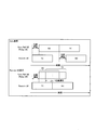
- the UE 100-1 transmits control information (SA Relay) for designating a monitor (reception) area (reception resource) of the UE 100-2.
- the monitor area corresponds to a radio resource included in the individual resource.
- the UE 100-1 transmits user data to the UE 100-2 in the designated monitor area (Data).
- the UE 100-2 monitors only the designated monitor area.
- the UE 100-2 transmits control information in the transmission area (SA Remote).
- the control information is information that designates the monitor area of the UE 100-1.
- the UE 100-2 transmits user data to the UE 100-1 in the designated monitor area (Data).
- the UE 100-1 monitors only the designated monitor area.
- the UE 100-1 may transmit control information (SA Relay) for designating a monitor (reception) area (reception resource) of the UE 100-2 and a transmission area (transmission resource) of the UE 100-2.
- the monitor area and the transmission area correspond to radio resources included in the individual resources.
- the UE 100-1 transmits user data to the UE 100-2 in the designated monitor area (Data).
- the UE 100-2 monitors only the designated monitor area.
- the UE 100-2 transmits the control information in the designated transmission area (SA Remote).
- the control information is information that designates the monitoring area of the UE 100-1 and the transmission area of the UE 100-1.
- the UE 100-2 transmits user data to the UE 100-1 in the designated monitor area (Data).
- the UE 100-1 monitors only the designated monitor area.
- the UE 100-1 transmits control information in the designated transmission area (SA Relay).
- the control information is information that designates the monitoring area of UE 100-2 (and the transmission area of UE 100-1). The
- control information is used for specifying the position of the radio resource where the user data is arranged.
- the UE 100-2 executes a side link DRX (SL-DRX: Sidelink-Discontinuous Reception) operation.
- the SL-DRX operation is an operation for discontinuously monitoring a plurality of control areas.
- the UE 100-2 monitors the control area according to a predetermined cycle (SL-DRX cycle). For example, when monitoring one control area, the UE 100-2 omits monitoring of the control area until the SL-DRX cycle elapses.
- the SL-DRX cycle is a length of a control area period (SA period) unit. For example, as shown in FIG. 11, when the SL-DRX cycle is twice the period of the control region, the UE 100-2 omits monitoring of the second (and fourth) control region. Thereby, since UE100-2 can reduce the area to monitor, it can reduce power consumption.
- the UE 100-1 may select a control region used for transmission of control information from among a plurality of control regions according to the SLDRX operation (SL-DRX cycle).
- the UE 100-1 can select the first (and third) control region as a control region used for transmission of control information.
- UE 100-1 acquires setting information (for example, SLDRX cycle) of SL-DRX operation from UE 100-2.
- the UE 100-1 may transmit the setting information of the SL-DRX operation to the UE 100-2.
- the UE 100-1 may receive setting information of SL-DRX operation from the eNB 200.
- SL-DRX operation setting information may be different for each UE.
- the setting information of SL-DRX operation may be common to each UE.
- UE 100-1 may transmit power control information to UE 100-2 in side link communication.
- FIG. 12 is an example of power control by an open loop TPC (Transmission Power Control).
- FIG. 13 is an example of power control by closed loop TPC.
- the UE 100-1 transmits power control information including parameter information (TPC parameters) for controlling transmission power from the UE 100-2 to the UE 100-1 to the UE 100-2.
- the UE 100-1 may transmit power control information by MIB-SL and / or SIB-SL.
- the parameter information is determined according to the received power of the side link signal from UE 100-1 to UE 100-2.
- the UE 100-2 may measure the reception power (reception strength (S-RSRP) and / or reception quality (S-RSRQ)) of a reference signal in an RB (resource block) in which PSBCH is transmitted.
- the UE 100-2 can measure the received power of SLSS from the UE 100-1.
- the UE 100-1 may periodically transmit SLSS.
- the UE 100-2 may measure the reception power (reception strength (SD-RSRP) and / or reception quality (SD-RSRQ)) of the reference signal in the RB through which the PSDCH is transmitted.
- SD-RSRP reception strength
- SD-RSRQ reception quality
- the parameter information may include a path loss compensation coefficient ⁇ .
- the parameter information may include the desired received power Po.
- the UE 100-2 calculates transmission power by the following equation.
- TxPower min (Pmax, Po + ⁇ * PL)
- TxPower indicates transmission power.
- PL indicates a path loss between UEs (between a remote UE and a relay UE).
- UE 100-2 determines the reception power of the side link signal to UE 100-1 based on the measurement result and the parameter information.
- the UE 100-2 transmits a side link signal to the UE 100-1.
- the UE 100-1 measures the received power of the side link signal (at least one of S-RSRP, S-RSRQ, SD-RSRP, and SD-RSRQ).
- the UE 100-1 transmits power control information including command information (TPC command) for controlling transmission power from UE 100-2 to UE 100-1 to UE 100-2.
- the UE 100-1 may transmit power control information (command information) to the UE 100-2 by control information (SCI: Sidelink Control Information) transmitted on the PSCCH.
- the UE 100-1 may transmit power control information (command information) to the UE 100-2 by a discovery message.
- the UE 100-1 may transmit power control information (command information) to the UE 100-2 by a packet (data) transmitted by the PSSCH.
- the UE 100 may include command information in the MAC header of the packet.
- the command information may be any of an instruction to increase transmission power, an instruction to decrease transmission power, and an instruction to maintain transmission power.
- the instruction to increase (substantially) transmission power may be a transmission power value (variable value) to be increased.
- the instruction to (substantially) decrease the transmission power may be a transmission power value (variable value) to decrease.
- the command information is one of an instruction to transmit at the maximum transmission power of the UE 100-2, an instruction to transmit at the minimum transmission power of the UE 100-2, an instruction based on S-RSRP, and an instruction based on SD-RSRP. There may be. When S-RSRP is used as a reference, the transmission power is calculated based on S-RSRP.
- the path loss (PL) used for calculating the transmission power described above is calculated by S-RSRP.
- transmission power is calculated based on SD-RSRP.
- the path loss (PL) used for calculating the transmission power described above is calculated by SD-RSRP.
- the command information may be an instruction to match RSRP indicating the received power intensity of the reference signal from the eNB 200.
- the UE 100-1 may transmit the RSRP measured by itself to the UE 100-2.
- the UE 100-2 can adjust the transmission power of the side link signal according to the reception power of the side link signal between the UE 100-1 and the UE 100-2.
- the transmission power of the side link signal is the downlink signal reception power (RSRP) between the eNB 200 and the UE 100-2.
- the transmission power can be adjusted appropriately rather than adjusting. As a result, power consumption can be reduced.
- the interference given to eNB200 and other UE100 can be suppressed.
- Modification Example 1 Modification Example 1 according to the embodiment will be described with reference to FIG.
- FIG. 14 is a sequence diagram for explaining the first modification.
- the UE 100-2 transmits the relay request without using the radio resource included in the SIB-SL (Data).
- the UE 100-2 stores in advance radio resources for requesting relaying by the proximity service.
- the radio resource information may be a fixed value stored when the UE 100-2 (memory) is manufactured.
- the radio resource may be stored in, for example, a SIM (D2D SIM) that does not have a cellular communication function.
- Step S201 corresponds to step S101.
- the UE 100-2 may start the process of step S202 in response to reception of SLSS and / or MIB-SL.
- Step S202 corresponds to step S104.
- the UE 100-2 requests the UE 100-1 to relay by the proximity service using the radio resources stored in advance.
- Steps S203 to S211 correspond to steps S105 to S113.
- FIG. 15 is a sequence diagram for explaining the second modification.
- the UE 100-1 starts transmission of SLSS / MIB-SL in response to reception of the side link signal from the UE 100-2.
- step S301 the UE 100-2 transmits SLSS and / or MIB-SL on the side link.
- radio resources used only for transmitting SLSS and / or MIB-SL are stored in advance.
- the radio resource information may be a fixed value stored when the UE 100-2 (memory) is manufactured.
- the radio resource may be stored in, for example, a SIM (D2D SIM) that does not have a cellular communication function.
- the UE 100-2 may include an identifier (SLSS ID) indicating that it is a remote UE in the SLSS.
- the UE 100-1 may include information indicating that it is a remote UE in the MIB-SL.
- the UE 100-1 When the UE 100-1 receives the SLSS and / or MIB-SL from the UE 100-2, the UE 100-1 starts the process of step S302. When the UE 100-2 receives the SLSS and / or MIB-SL from the UE 100-1, the UE 100-2 stops the transmission of the SLSS and / or MIB-SL. Thereby, transmission of SLSS and / or MIB-SL is taken over from UE 100-2 to UE 100-1.
- Step S302 corresponds to step S101.
- the UE 100-1 transmits SLSS and / or MIB-SL at a timing different from the timing indicated by the offset indicator included in the received SLSS and / or MIB-SL.
- the UE 100-1 may include an identifier (SLSS ID) indicating that it is a relay UE in the SLSS.
- the UE 100-1 may include information indicating that it is a relay UE in the MIB-SL.
- Steps S303 to S314 correspond to Steps S102 to S113.
- FIG. 16 is a sequence diagram for explaining the third modification.
- the eNB 200 transmits SLSS / MIB-SL.
- step S401 the eNB 200 transmits (periodically) SLSS and / or MIB-SL on the side link.
- the eNB 200 may transmit (periodically) the SIB-SL on the side link.
- Information on radio resources for initial access may be included in at least one of SLSS, MIB-SL, and SIB-SL.
- the eNB 200 has a side link transmission / reception function.
- the eNB 200 may transmit a side link signal (SLSS and / or MIB-SL) in the side link as a cell.
- the UE that has received the side link signal recognizes the transmission source of the side link signal as a cell (eNB 200).
- the eNB 200 may transmit a side link signal in the side link as a UE.
- the UE that has received the side link signal recognizes the transmission source of the side link signal as the UE.
- the UE 100-2 transmits a side link signal (for example, a discovery message) using the radio resource information received from the eNB 200.
- the side link signal may include information indicating a relay request.
- the UE 100-1 When the UE 100-1 receives SLSS and / or MIB-SL from the UE 100-2, the UE 100-1 starts the process of step S403.
- the UE 100-1 may transmit information indicating the start of transmission of SLSS and / or MIB-SL to the eNB 200 in the uplink or side link (step S404).
- the eNB 200 may stop transmission of SLSS and / or MIB-SL. Thereby, transmission of SLSS and / or MIB-SL is taken over from eNB200 to UE100-1.
- UE100-1 does not need to transmit the information of step S404 to eNB200.
- Steps S403 and S405 to S416 correspond to steps S101 to S113.
- power saving operations (sharing of individual resources, SL-DRX operation, and transmission power control) for reducing power consumption were performed in side link communication for relaying in a nearby service. Not limited to this.
- a power saving operation may be executed.
- a power saving operation may be executed.
- the UE 100-1 as the relay UE may execute the SL-DRX operation.
- the remote UE 100-2 may send power control information to the UE 100-1.
- a program for causing a computer to execute each process performed by any of the above-described nodes may be provided.
- the program may be recorded on a computer readable medium. If a computer-readable medium is used, a program can be installed in the computer.
- the computer-readable medium on which the program is recorded may be a non-transitory recording medium.
- the non-transitory recording medium is not particularly limited, but may be a recording medium such as a CD-ROM or a DVD-ROM.
- a chip configured by a memory that stores a program for executing each process performed by either the UE 100 or the eNB 200 and a processor that executes the program stored in the memory may be provided.
- the LTE system has been described as an example of the mobile communication system, but the present invention is not limited to the LTE system, and the content according to the present application may be applied to a system other than the LTE system.
Landscapes
- Engineering & Computer Science (AREA)
- Signal Processing (AREA)
- Computer Networks & Wireless Communication (AREA)
- Databases & Information Systems (AREA)
- Mobile Radio Communication Systems (AREA)
Abstract
Un terminal sans fil selon un mode de réalisation de l'invention est pourvu d'un contrôleur au moyen duquel il est possible de relayer un trafic entre d'autres terminaux sans fil et un réseau par le biais d'un service de proximité. Le contrôleur exécute une commande pour la transmission de premières informations et de secondes informations dans une liaison périphérique. Les premières informations sont utilisées pour spécifier la position d'une ressource sans fil dans laquelle sont disposées les secondes informations. Les secondes informations sont utilisées en vue de spécifier la position d'une ressource sans fil pour demander un relais au moyen du service de proximité.
Priority Applications (2)
| Application Number | Priority Date | Filing Date | Title |
|---|---|---|---|
| US16/076,335 US10716155B2 (en) | 2016-02-08 | 2017-01-30 | Radio terminal |
| JP2017566579A JP6910310B2 (ja) | 2016-02-08 | 2017-01-30 | 無線端末 |
Applications Claiming Priority (2)
| Application Number | Priority Date | Filing Date | Title |
|---|---|---|---|
| JP2016022242 | 2016-02-08 | ||
| JP2016-022242 | 2016-02-08 |
Publications (1)
| Publication Number | Publication Date |
|---|---|
| WO2017138378A1 true WO2017138378A1 (fr) | 2017-08-17 |
Family
ID=59563249
Family Applications (1)
| Application Number | Title | Priority Date | Filing Date |
|---|---|---|---|
| PCT/JP2017/003105 Ceased WO2017138378A1 (fr) | 2016-02-08 | 2017-01-30 | Terminal sans fil |
Country Status (3)
| Country | Link |
|---|---|
| US (1) | US10716155B2 (fr) |
| JP (1) | JP6910310B2 (fr) |
| WO (1) | WO2017138378A1 (fr) |
Cited By (19)
| Publication number | Priority date | Publication date | Assignee | Title |
|---|---|---|---|---|
| KR20190039101A (ko) * | 2016-08-11 | 2019-04-10 | 소니 주식회사 | 네트워크 제어 단말기 및 네트워크 노드에 사용되는 전자 디바이스 및 방법 |
| WO2020008542A1 (fr) * | 2018-07-03 | 2020-01-09 | 株式会社Nttドコモ | Dispositif utilisateur |
| WO2021139554A1 (fr) * | 2020-01-10 | 2021-07-15 | 上海朗帛通信技术有限公司 | Procédé et dispositif pour réception discontinue |
| CN113271618A (zh) * | 2020-02-14 | 2021-08-17 | 华为技术有限公司 | 一种功率控制方法及相关装置 |
| CN113395749A (zh) * | 2020-03-13 | 2021-09-14 | 维沃移动通信有限公司 | 传输配置方法及电子设备 |
| JP2022517076A (ja) * | 2019-01-11 | 2022-03-04 | 華為技術有限公司 | 電力制御方法および電力制御装置 |
| WO2022075321A1 (fr) * | 2020-10-06 | 2022-04-14 | 京セラ株式会社 | Procédé de commande de communication |
| JP2022543809A (ja) * | 2019-08-08 | 2022-10-14 | クアルコム,インコーポレイテッド | サイドリンク閉ループ送信電力制御コマンド処理 |
| JP2023509936A (ja) * | 2020-01-07 | 2023-03-10 | エルジー エレクトロニクス インコーポレイティド | 無線通信システムにおいて端末が信号を送受信する方法 |
| JP2023513443A (ja) * | 2020-02-13 | 2023-03-31 | 中興通訊股▲ふん▼有限公司 | サイドリンク通信のための方法およびデバイス |
| JP2023516475A (ja) * | 2020-03-12 | 2023-04-19 | 北京小米移動軟件有限公司 | ダイレクトリンクにおける宛先アドレスの選択方法、装置及び記憶媒体 |
| JP2023518660A (ja) * | 2020-02-07 | 2023-05-08 | オッポ広東移動通信有限公司 | データ伝送方法及びパラメータ調整方法、装置、端末機器 |
| JP2023536315A (ja) * | 2020-08-06 | 2023-08-24 | 中興通訊股▲ふん▼有限公司 | サイドリンク伝送を管理する方法およびデバイス |
| JP2023536419A (ja) * | 2020-07-29 | 2023-08-25 | エルジー エレクトロニクス インコーポレイティド | Nr v2xにおける省電力モード別drx動作を実行する方法及び装置 |
| JP2023547363A (ja) * | 2020-10-22 | 2023-11-10 | パナソニック インテレクチュアル プロパティ コーポレーション オブ アメリカ | サイドリンクブロードキャストのための通信装置および通信方法 |
| JP2024511493A (ja) * | 2021-03-29 | 2024-03-13 | 大唐移▲動▼通信▲設▼▲備▼有限公司 | 直接通信インターフェースのdrx及び/又はdtx状態の維持方法及び直接通信端末 |
| WO2024053054A1 (fr) * | 2022-09-08 | 2024-03-14 | 本田技研工業株式会社 | Dispositif terminal et procédé de commande de communication |
| WO2024116652A1 (fr) * | 2022-11-30 | 2024-06-06 | キヤノン株式会社 | Dispositif de communication, procédé de commande, et programme |
| JP2024525849A (ja) * | 2021-07-16 | 2024-07-12 | エルジー エレクトロニクス インコーポレイティド | Nr v2xにおけるsl drx動作下でリソース再選択を介してリソースを接続する方法及び装置 |
Families Citing this family (36)
| Publication number | Priority date | Publication date | Assignee | Title |
|---|---|---|---|---|
| CN106211026B (zh) * | 2014-12-22 | 2019-05-24 | 中兴通讯股份有限公司 | 一种实现设备直通中继选择的方法、网络控制节点及用户设备 |
| EP3554158B1 (fr) * | 2016-12-27 | 2024-09-04 | Huawei Technologies Co., Ltd. | Procédé de transmission d'informations de système et dispositif terminal |
| CN108633074B (zh) * | 2017-03-23 | 2022-05-13 | 华硕电脑股份有限公司 | 无线通信系统中报告侧链路服务的辅助信息的方法和设备 |
| WO2018174691A1 (fr) * | 2017-03-24 | 2018-09-27 | 엘지전자 주식회사 | Procédé de transmission d'un signal de synchronisation de liaison latérale dans un système de communication sans fil, et terminal utilisant ce procédé |
| KR102247830B1 (ko) * | 2017-06-02 | 2021-05-04 | 삼성전자 주식회사 | D2d 무선 통신을 지원하는 단말 및 이의 전력 제어 방법 |
| CN110381573B (zh) * | 2018-04-12 | 2021-11-09 | 维沃移动通信有限公司 | 旁链路的功率控制方法及终端设备 |
| US11672035B2 (en) * | 2018-06-14 | 2023-06-06 | Lg Electronics Inc. | Method and apparatus for performing sidelink communication by UE in NR V2X |
| US11363520B2 (en) * | 2018-11-20 | 2022-06-14 | Qualcomm Incorporated | Relay discovery in a wireless network |
| US11477764B2 (en) * | 2019-07-31 | 2022-10-18 | Qualcomm Incorporated | Transmitting system information on sidelink |
| EP3780891A1 (fr) * | 2019-08-01 | 2021-02-17 | ASUSTek Computer Inc. | Procédé et appareil pour fournir de l'économisation d'énergie lors de la surveillance de communications d'appareil-à-appareil dans un système de communication sans fil |
| CN114270889B (zh) * | 2019-08-12 | 2025-04-01 | Lg电子株式会社 | 用于在无线通信系统中操作与副链路drx关联的ue的方法和设备 |
| US11432255B2 (en) * | 2019-08-15 | 2022-08-30 | Qualcomm Incorporated | Reference timing determination based on sidelink propagation delay |
| KR102856797B1 (ko) * | 2019-08-16 | 2025-09-05 | 현대자동차주식회사 | 통신 시스템에서 사이드링크 자원의 설정 방법 |
| US11516876B2 (en) * | 2019-08-19 | 2022-11-29 | Qualcomm Incorporated | Discontinuous reception configuration for sidelink |
| CN111800893B (zh) * | 2019-08-22 | 2022-06-17 | 维沃移动通信有限公司 | 边链路非连续发送、接收方法与装置及终端设备 |
| WO2021034165A1 (fr) * | 2019-08-22 | 2021-02-25 | 엘지전자 주식회사 | Procédé au moyen duquel un terminal effectue une communication de liaison latérale dans un système de communication sans fil permettant de prendre en charge une liaison latérale, et dispositif associé |
| CN111800764B (zh) * | 2019-08-22 | 2022-05-13 | 维沃移动通信有限公司 | 边链路drx参数配置方法、装置及终端设备 |
| US12245150B2 (en) | 2019-09-27 | 2025-03-04 | Kt Corporation | Method for controlling sidelink communication, and device therefor |
| KR20220097937A (ko) * | 2020-01-09 | 2022-07-08 | 엘지전자 주식회사 | 무선통신시스템에서 신호를 송수신하는 방법 |
| CN113133096B (zh) * | 2020-01-15 | 2023-03-28 | 大唐移动通信设备有限公司 | 一种信息确定方法、装置、设备及计算机可读存储介质 |
| CN113141598B (zh) * | 2020-01-16 | 2022-03-29 | 上海朗帛通信技术有限公司 | 一种用于不连续接收的无线通信的方法和装置 |
| EP4039019A1 (fr) | 2020-01-16 | 2022-08-10 | Shanghai Langbo Communication Technology Company Limited | Procédé et dispositif utilisés pour une communication sans fil avec une réception discontinue |
| CN113163358B (zh) | 2020-01-22 | 2024-07-05 | 华为技术有限公司 | 配置使能方法及装置 |
| JP7440645B2 (ja) * | 2020-02-13 | 2024-02-28 | 中興通訊股▲ふん▼有限公司 | サイドリンク通信のための方法およびデバイス |
| US12022556B2 (en) * | 2020-02-28 | 2024-06-25 | Qualcomm Incorporated | Maintaining sidelink (SL) connectivity for SL configured with discontinuous reception (DRX) |
| CN113453317B (zh) * | 2020-03-25 | 2024-01-05 | 华为技术有限公司 | 一种侧行链路通信方法及装置 |
| WO2021206371A1 (fr) * | 2020-04-07 | 2021-10-14 | 주식회사 케이티 | Procédé de commande de communication de liaison latérale et dispositif associé |
| US11723016B2 (en) * | 2020-05-07 | 2023-08-08 | Qualcomm Incorporated | Physical sidelink channel packet-based synchronization |
| WO2021232176A1 (fr) * | 2020-05-17 | 2021-11-25 | Qualcomm Incorporated | Réception discontinue pour communications de liaison latérale dans des systèmes de communication sans fil |
| CN115735385B (zh) * | 2020-06-09 | 2025-03-11 | 高通股份有限公司 | 功率模式配置之间的动态切换 |
| US11903080B2 (en) * | 2020-07-24 | 2024-02-13 | Samsung Electronics Co., Ltd. | Method and apparatus for discontinuous reception operations of sidelink groupcast/broadcast |
| WO2022027593A1 (fr) * | 2020-08-07 | 2022-02-10 | Mediatek Inc. | Mécanisme drx de liaison latérale pour économie d'énergie |
| US20220110141A1 (en) * | 2020-10-02 | 2022-04-07 | Qualcomm Incorporated | Sidelink transmission from relay user equipment (ue) to remote ue |
| WO2022155348A1 (fr) * | 2021-01-13 | 2022-07-21 | Ofinno, Llc | Opération de réception discontinue de liaison latérale |
| CN114765837B (zh) * | 2021-01-15 | 2024-05-07 | 维沃移动通信有限公司 | 省电处理方法、装置及设备 |
| CN116847324A (zh) * | 2022-03-25 | 2023-10-03 | 维沃移动通信有限公司 | 通信方法、装置和设备 |
Citations (1)
| Publication number | Priority date | Publication date | Assignee | Title |
|---|---|---|---|---|
| WO2015115505A1 (fr) * | 2014-01-31 | 2015-08-06 | 京セラ株式会社 | Système de communication mobile et terminal d'utilisateur |
-
2017
- 2017-01-30 WO PCT/JP2017/003105 patent/WO2017138378A1/fr not_active Ceased
- 2017-01-30 US US16/076,335 patent/US10716155B2/en active Active
- 2017-01-30 JP JP2017566579A patent/JP6910310B2/ja active Active
Patent Citations (1)
| Publication number | Priority date | Publication date | Assignee | Title |
|---|---|---|---|---|
| WO2015115505A1 (fr) * | 2014-01-31 | 2015-08-06 | 京セラ株式会社 | Système de communication mobile et terminal d'utilisateur |
Non-Patent Citations (3)
| Title |
|---|
| ERICSSON: "Relay reselection with Model B", 3GPP TSG-RAN WG2#92 R2-156578, 7 November 2015 (2015-11-07), XP051005956 * |
| ERICSSON: "Sidelink Resource Allocation in V2X", 3GPP TSG-RAN WG2#93 R2-161566, 6 February 2016 (2016-02-06), XP051055404 * |
| ITRI: "Clarifications to Resource Allocation for ProSe UE-to-Network Relay Discovery", 3GPP TSG- RAN WG2#93 R2-161330, 5 February 2016 (2016-02-05), XP051055240 * |
Cited By (43)
| Publication number | Priority date | Publication date | Assignee | Title |
|---|---|---|---|---|
| JP7246302B2 (ja) | 2016-08-11 | 2023-03-27 | ソニーグループ株式会社 | ネットワーク制御端末及びネットワークノードに用いられる電子装置及び方法 |
| US12160822B2 (en) | 2016-08-11 | 2024-12-03 | Sony Group Corporation | Electronic device and method used for network control terminal and network node |
| JP2019525607A (ja) * | 2016-08-11 | 2019-09-05 | ソニー株式会社 | ネットワーク制御端末及びネットワークノードに用いられる電子装置及び方法 |
| KR102423403B1 (ko) | 2016-08-11 | 2022-07-22 | 소니그룹주식회사 | 네트워크 제어 단말기 및 네트워크 노드에 사용되는 전자 디바이스 및 방법 |
| KR20190039101A (ko) * | 2016-08-11 | 2019-04-10 | 소니 주식회사 | 네트워크 제어 단말기 및 네트워크 노드에 사용되는 전자 디바이스 및 방법 |
| WO2020008542A1 (fr) * | 2018-07-03 | 2020-01-09 | 株式会社Nttドコモ | Dispositif utilisateur |
| JP2022517076A (ja) * | 2019-01-11 | 2022-03-04 | 華為技術有限公司 | 電力制御方法および電力制御装置 |
| US11856393B2 (en) | 2019-01-11 | 2023-12-26 | Huawei Technologies Co., Ltd. | Power control method and power control apparatus |
| JP7259049B2 (ja) | 2019-01-11 | 2023-04-17 | 華為技術有限公司 | 電力制御方法および電力制御装置 |
| JP2022543809A (ja) * | 2019-08-08 | 2022-10-14 | クアルコム,インコーポレイテッド | サイドリンク閉ループ送信電力制御コマンド処理 |
| JP2023509936A (ja) * | 2020-01-07 | 2023-03-10 | エルジー エレクトロニクス インコーポレイティド | 無線通信システムにおいて端末が信号を送受信する方法 |
| JP7338066B2 (ja) | 2020-01-07 | 2023-09-04 | エルジー エレクトロニクス インコーポレイティド | 無線通信システムにおいて端末が信号を送受信する方法 |
| WO2021139554A1 (fr) * | 2020-01-10 | 2021-07-15 | 上海朗帛通信技术有限公司 | Procédé et dispositif pour réception discontinue |
| JP7526274B2 (ja) | 2020-02-07 | 2024-07-31 | オッポ広東移動通信有限公司 | データ伝送方法及びパラメータ調整方法、装置、端末機器 |
| US12520373B2 (en) | 2020-02-07 | 2026-01-06 | Guangdong Oppo Mobile Telecommunications Corp., Ltd. | Method and apparatus for sidelink data transmission during a discontinuous reception (DRX) on duration of a sidelink receiving device |
| JP2023518660A (ja) * | 2020-02-07 | 2023-05-08 | オッポ広東移動通信有限公司 | データ伝送方法及びパラメータ調整方法、装置、端末機器 |
| JP7462766B2 (ja) | 2020-02-13 | 2024-04-05 | 中興通訊股▲ふん▼有限公司 | サイドリンク通信のための方法およびデバイス |
| JP2023513443A (ja) * | 2020-02-13 | 2023-03-31 | 中興通訊股▲ふん▼有限公司 | サイドリンク通信のための方法およびデバイス |
| JP2024069697A (ja) * | 2020-02-13 | 2024-05-21 | 中興通訊股▲ふん▼有限公司 | サイドリンク通信のための方法およびデバイス |
| JP7641420B2 (ja) | 2020-02-13 | 2025-03-06 | 中興通訊股▲ふん▼有限公司 | サイドリンク通信のための方法およびデバイス |
| US12302444B2 (en) | 2020-02-13 | 2025-05-13 | Zte Corporation | Method and device for sidelink communication |
| CN113271618B (zh) * | 2020-02-14 | 2023-04-11 | 华为技术有限公司 | 一种功率控制方法及相关装置 |
| CN113271618A (zh) * | 2020-02-14 | 2021-08-17 | 华为技术有限公司 | 一种功率控制方法及相关装置 |
| JP7425890B2 (ja) | 2020-03-12 | 2024-01-31 | 北京小米移動軟件有限公司 | ダイレクトリンクにおける宛先アドレスの選択方法、装置及び記憶媒体 |
| JP2023516475A (ja) * | 2020-03-12 | 2023-04-19 | 北京小米移動軟件有限公司 | ダイレクトリンクにおける宛先アドレスの選択方法、装置及び記憶媒体 |
| CN113395749A (zh) * | 2020-03-13 | 2021-09-14 | 维沃移动通信有限公司 | 传输配置方法及电子设备 |
| CN113395749B (zh) * | 2020-03-13 | 2023-04-07 | 维沃移动通信有限公司 | 传输配置方法及电子设备 |
| JP2023536419A (ja) * | 2020-07-29 | 2023-08-25 | エルジー エレクトロニクス インコーポレイティド | Nr v2xにおける省電力モード別drx動作を実行する方法及び装置 |
| JP7607114B2 (ja) | 2020-07-29 | 2024-12-26 | エルジー エレクトロニクス インコーポレイティド | Nr v2xにおける省電力モード別drx動作を実行する方法及び装置 |
| JP2023536315A (ja) * | 2020-08-06 | 2023-08-24 | 中興通訊股▲ふん▼有限公司 | サイドリンク伝送を管理する方法およびデバイス |
| JP7406003B2 (ja) | 2020-10-06 | 2023-12-26 | 京セラ株式会社 | 通信制御方法、ユーザ装置及びプロセッサ |
| JP2024023674A (ja) * | 2020-10-06 | 2024-02-21 | 京セラ株式会社 | 通信制御方法、ユーザ装置、プロセッサ、通信システム及びプログラム |
| JPWO2022075321A1 (fr) * | 2020-10-06 | 2022-04-14 | ||
| JP7631492B2 (ja) | 2020-10-06 | 2025-02-18 | 京セラ株式会社 | 通信制御方法、ユーザ装置、プロセッサ、通信システム及びプログラム |
| WO2022075321A1 (fr) * | 2020-10-06 | 2022-04-14 | 京セラ株式会社 | Procédé de commande de communication |
| JP2023547363A (ja) * | 2020-10-22 | 2023-11-10 | パナソニック インテレクチュアル プロパティ コーポレーション オブ アメリカ | サイドリンクブロードキャストのための通信装置および通信方法 |
| JP7574469B2 (ja) | 2021-03-29 | 2024-10-28 | 大唐移▲動▼通信▲設▼▲備▼有限公司 | 直接通信インターフェースのdrx及び/又はdtx状態の維持方法及び直接通信端末 |
| JP2024511493A (ja) * | 2021-03-29 | 2024-03-13 | 大唐移▲動▼通信▲設▼▲備▼有限公司 | 直接通信インターフェースのdrx及び/又はdtx状態の維持方法及び直接通信端末 |
| US12588103B2 (en) | 2021-03-29 | 2026-03-24 | Datang Mobile Communications Equipment Co., Ltd. | Method for maintaining DRX and/or DTX state of sidelink communication interface, and sidelink communication terminals |
| JP2024525849A (ja) * | 2021-07-16 | 2024-07-12 | エルジー エレクトロニクス インコーポレイティド | Nr v2xにおけるsl drx動作下でリソース再選択を介してリソースを接続する方法及び装置 |
| JPWO2024053054A1 (fr) * | 2022-09-08 | 2024-03-14 | ||
| WO2024053054A1 (fr) * | 2022-09-08 | 2024-03-14 | 本田技研工業株式会社 | Dispositif terminal et procédé de commande de communication |
| WO2024116652A1 (fr) * | 2022-11-30 | 2024-06-06 | キヤノン株式会社 | Dispositif de communication, procédé de commande, et programme |
Also Published As
| Publication number | Publication date |
|---|---|
| US20190053305A1 (en) | 2019-02-14 |
| US10716155B2 (en) | 2020-07-14 |
| JP6910310B2 (ja) | 2021-07-28 |
| JPWO2017138378A1 (ja) | 2018-11-29 |
Similar Documents
| Publication | Publication Date | Title |
|---|---|---|
| JP6910310B2 (ja) | 無線端末 | |
| US9820111B2 (en) | Communication control method and user terminal for selecting synchronization reference of device-to-device (D2D) | |
| US10631223B2 (en) | Communication method and communication device | |
| JP6295316B2 (ja) | 基地局及びプロセッサ | |
| US10477380B2 (en) | Base station and radio terminal | |
| JP6169442B2 (ja) | 移動通信システム及びユーザ端末 | |
| JP6670929B2 (ja) | 無線端末及び基地局 | |
| JP6062088B2 (ja) | ユーザ端末、及びプロセッサ | |
| US20150304969A1 (en) | Communication control method, base station, user terminal, processor, and storage medium | |
| WO2014163138A1 (fr) | Station de base | |
| JP6773778B2 (ja) | 無線端末及び基地局 | |
| WO2017026409A1 (fr) | Terminal sans fil | |
| JP6298218B2 (ja) | 通信方法、無線端末、プロセッサ及び基地局 | |
| JP2017200223A (ja) | ユーザ端末、移動通信システム及び方法 | |
| WO2016021701A1 (fr) | Station de base et terminal utilisateur |
Legal Events
| Date | Code | Title | Description |
|---|---|---|---|
| 121 | Ep: the epo has been informed by wipo that ep was designated in this application |
Ref document number: 17750103 Country of ref document: EP Kind code of ref document: A1 |
|
| WWE | Wipo information: entry into national phase |
Ref document number: 2017566579 Country of ref document: JP |
|
| NENP | Non-entry into the national phase |
Ref country code: DE |
|
| 122 | Ep: pct application non-entry in european phase |
Ref document number: 17750103 Country of ref document: EP Kind code of ref document: A1 |