EP4093361B1 - Verbindungsanordnung, verbindungssystem, behälter und behältersystem - Google Patents
Verbindungsanordnung, verbindungssystem, behälter und behältersystem Download PDFInfo
- Publication number
- EP4093361B1 EP4093361B1 EP21701503.1A EP21701503A EP4093361B1 EP 4093361 B1 EP4093361 B1 EP 4093361B1 EP 21701503 A EP21701503 A EP 21701503A EP 4093361 B1 EP4093361 B1 EP 4093361B1
- Authority
- EP
- European Patent Office
- Prior art keywords
- arrangement
- container
- connecting arrangement
- coupling
- axis
- Prior art date
- Legal status (The legal status is an assumption and is not a legal conclusion. Google has not performed a legal analysis and makes no representation as to the accuracy of the status listed.)
- Active
Links
Images




Classifications
-
- A—HUMAN NECESSITIES
- A61—MEDICAL OR VETERINARY SCIENCE; HYGIENE
- A61J—CONTAINERS SPECIALLY ADAPTED FOR MEDICAL OR PHARMACEUTICAL PURPOSES; DEVICES OR METHODS SPECIALLY ADAPTED FOR BRINGING PHARMACEUTICAL PRODUCTS INTO PARTICULAR PHYSICAL OR ADMINISTERING FORMS; DEVICES FOR ADMINISTERING FOOD OR MEDICINES ORALLY; BABY COMFORTERS; DEVICES FOR RECEIVING SPITTLE
- A61J1/00—Containers specially adapted for medical or pharmaceutical purposes
- A61J1/14—Details; Accessories therefor
- A61J1/20—Arrangements for transferring or mixing fluids, e.g. from vial to syringe
- A61J1/2089—Containers or vials which are to be joined to each other in order to mix their contents
-
- A—HUMAN NECESSITIES
- A61—MEDICAL OR VETERINARY SCIENCE; HYGIENE
- A61J—CONTAINERS SPECIALLY ADAPTED FOR MEDICAL OR PHARMACEUTICAL PURPOSES; DEVICES OR METHODS SPECIALLY ADAPTED FOR BRINGING PHARMACEUTICAL PRODUCTS INTO PARTICULAR PHYSICAL OR ADMINISTERING FORMS; DEVICES FOR ADMINISTERING FOOD OR MEDICINES ORALLY; BABY COMFORTERS; DEVICES FOR RECEIVING SPITTLE
- A61J1/00—Containers specially adapted for medical or pharmaceutical purposes
- A61J1/14—Details; Accessories therefor
- A61J1/20—Arrangements for transferring or mixing fluids, e.g. from vial to syringe
- A61J1/2003—Accessories used in combination with means for transfer or mixing of fluids, e.g. for activating fluid flow, separating fluids, filtering fluid or venting
- A61J1/2006—Piercing means
- A61J1/201—Piercing means having one piercing end
-
- A—HUMAN NECESSITIES
- A61—MEDICAL OR VETERINARY SCIENCE; HYGIENE
- A61J—CONTAINERS SPECIALLY ADAPTED FOR MEDICAL OR PHARMACEUTICAL PURPOSES; DEVICES OR METHODS SPECIALLY ADAPTED FOR BRINGING PHARMACEUTICAL PRODUCTS INTO PARTICULAR PHYSICAL OR ADMINISTERING FORMS; DEVICES FOR ADMINISTERING FOOD OR MEDICINES ORALLY; BABY COMFORTERS; DEVICES FOR RECEIVING SPITTLE
- A61J1/00—Containers specially adapted for medical or pharmaceutical purposes
- A61J1/14—Details; Accessories therefor
- A61J1/20—Arrangements for transferring or mixing fluids, e.g. from vial to syringe
- A61J1/2003—Accessories used in combination with means for transfer or mixing of fluids, e.g. for activating fluid flow, separating fluids, filtering fluid or venting
- A61J1/202—Separating means
- A61J1/2027—Separating means having frangible parts
-
- B—PERFORMING OPERATIONS; TRANSPORTING
- B65—CONVEYING; PACKING; STORING; HANDLING THIN OR FILAMENTARY MATERIAL
- B65D—CONTAINERS FOR STORAGE OR TRANSPORT OF ARTICLES OR MATERIALS, e.g. BAGS, BARRELS, BOTTLES, BOXES, CANS, CARTONS, CRATES, DRUMS, JARS, TANKS, HOPPERS, FORWARDING CONTAINERS; ACCESSORIES, CLOSURES, OR FITTINGS THEREFOR; PACKAGING ELEMENTS; PACKAGES
- B65D1/00—Rigid or semi-rigid containers having bodies formed in one piece, e.g. by casting metallic material, by moulding plastics, by blowing vitreous material, by throwing ceramic material, by moulding pulped fibrous material or by deep-drawing operations performed on sheet material
- B65D1/40—Details of walls
- B65D1/42—Reinforcing or strengthening parts or members
- B65D1/46—Local reinforcements, e.g. adjacent closures
-
- B—PERFORMING OPERATIONS; TRANSPORTING
- B65—CONVEYING; PACKING; STORING; HANDLING THIN OR FILAMENTARY MATERIAL
- B65D—CONTAINERS FOR STORAGE OR TRANSPORT OF ARTICLES OR MATERIALS, e.g. BAGS, BARRELS, BOTTLES, BOXES, CANS, CARTONS, CRATES, DRUMS, JARS, TANKS, HOPPERS, FORWARDING CONTAINERS; ACCESSORIES, CLOSURES, OR FITTINGS THEREFOR; PACKAGING ELEMENTS; PACKAGES
- B65D51/00—Closures not otherwise provided for
- B65D51/002—Closures to be pierced by an extracting-device for the contents and fixed on the container by separate retaining means
-
- B—PERFORMING OPERATIONS; TRANSPORTING
- B65—CONVEYING; PACKING; STORING; HANDLING THIN OR FILAMENTARY MATERIAL
- B65D—CONTAINERS FOR STORAGE OR TRANSPORT OF ARTICLES OR MATERIALS, e.g. BAGS, BARRELS, BOTTLES, BOXES, CANS, CARTONS, CRATES, DRUMS, JARS, TANKS, HOPPERS, FORWARDING CONTAINERS; ACCESSORIES, CLOSURES, OR FITTINGS THEREFOR; PACKAGING ELEMENTS; PACKAGES
- B65D81/00—Containers, packaging elements, or packages, for contents presenting particular transport or storage problems, or adapted to be used for non-packaging purposes after removal of contents
- B65D81/32—Containers, packaging elements, or packages, for contents presenting particular transport or storage problems, or adapted to be used for non-packaging purposes after removal of contents for packaging two or more different materials which must be maintained separate prior to use in admixture
- B65D81/3205—Separate rigid or semi-rigid containers joined to each other at their external surfaces
- B65D81/3211—Separate rigid or semi-rigid containers joined to each other at their external surfaces coaxially and provided with means facilitating admixture
Definitions
- the present invention relates in principle to the production of a fluidic connection or passage.
- the present invention relates to connecting arrangements, connecting systems, containers and container systems for producing a fluidic connection or passage between containers as well as to methods for their production.
- mixtures of medicaments or substances are produced in a mixing bottle, by transferring first the contents of one container and then of a second container into the mixing bottle, then closing the mixing bottle, and producing a mixture by agitation.
- the present invention thus also relates in particular to the production of a fluidic connection or passage which is sealed from the environment and prevents the ingress of foreign substances such as germs.
- WO 2013/104550 A discloses a kit for the production of a combined vaccine, wherein two bottles each have a septum and the kit comprises a double needle for piercing both septa and thereby providing a continuous fluidic connection between the bottles.
- the production of a fluidic connection by means of a double needle or the like leads to a relatively high flow resistance, which may make a transfer between the bottles a slow process.
- WO 2007/134392 A2 relates to a liquid storage device adapted to permit a substance to be selectively added to a liquid.
- the liquid storage device includes a liquid reservoir, a substance reservoir being connectable to the liquid reservoir for handling a single item without causing liquid transmission between the substance reservoir and the liquid reservoir and a manually operable means to selectively allow liquid transmission between the substance reservoir and the liquid reservoir.
- WO 2016/202465 A2 discloses a connecting and container system for producing a fluidic connection or passage by means of a bayonet-type movement.
- two separate connecting arrangements or containers that are each closed by the connecting arrangement are provided. These are coupled together, producing a continuous fluidic connection. The coupling takes place in two cuts.
- connecting arrangements are inserted translationally into one another, as a result of which one connecting arrangement is opened by perforation by means of the other connecting arrangement.
- the present invention proceeds from WO 2016/202465 A2 . It has been found that, based on the basic concept described herein, even easier operability or improved reliability is desirable.
- the problem addressed by the present disclosure is therefore to specify connecting arrangements, connecting systems, a container blank, containers, container systems and methods by means of which easier operability and/or increased reliability can be achieved.
- the present invention relates to a connecting system for producing a (continuous and/or irreversible) fluidic connection or passage.
- the connecting system has two mutually corresponding connecting arrangements.
- One or more of the connecting arrangements preferably (in each case) form a part, in particular a base / bottom, of a container.
- the connecting arrangement(s) can be inserted into a container blank and can be tightly connected, in particular welded, thereto.
- the (relevant) connecting arrangement forms an integral component of the container or is formed integrally with other parts of the container.
- a container may comprise a removal opening that allows access to an interior of the container for the purpose of removing contents.
- the removal opening may comprise a closure, in particular a septum.
- the connecting arrangement is preferably arranged on a side facing away from the closure or the removal opening, i.e. in addition to the removal opening.
- At least one of the containers is, and preferably both or all containers are, preferably (each) a bottle.
- a bottle has a bottle neck comprising the removal opening.
- the term "bottle" covers or the bottles is or are wide neck bottles, narrow neck bottles and/or jars having a neck.
- the containers are filled or can be filled with liquids, in particular vaccines. Alternatively, or additionally, the containers are filled or can be filled with other substances like powders, lyophilizates, or the like.
- the container(s) is/are closed in an initial state or delivery state by one of the connecting arrangements.
- the first step preferably opens one of the containers while the interior spaces of the containers are still separated by the closure of the other container.
- a tubular coupling arrangement preferably having a non-circular cross section, of the first connecting arrangement preferably acts on a closure of the second connecting arrangement, as a result of which the opening is produced.
- the coupling axis preferably corresponds to an axis of symmetry or central axis of the first connecting arrangement and/or the second connecting arrangement.
- a projection of the undeformed tubular coupling arrangement of the first connecting arrangement is preferably located within a mouth of the second connecting arrangement delimiting the opening or its closure.
- an inwardly facing circumferential surface of the non-circular mouth resembles an outwardly facing circumferential surface of the tubular coupling arrangement having a correspondingly non-circular cross section, such that they can be inserted into one another at least substantially without (radial) deformation.
- they preferably have a corresponding position, orientation and/or alignment relative to one another before and/or in the first step.
- a cutting edge of the first connecting arrangement can act on the closure of the second connecting arrangement.
- the closure may in particular be formed integrally with the parts of the second connecting arrangement retaining the closure and/or may be formed as a closure plate.
- the closure of the first connecting arrangement or the tubular coupling arrangement and/or the second connecting arrangement may be or may comprise films or membranes and/or plates.
- the closure(s) are preferably fragile, such that, by the first connecting arrangement acting on the second connecting arrangement, or vice versa, in particular the deformation of the tubular coupling arrangement, breaking and thereby the opening can be brought about.
- first connecting arrangement prefferably be open and for the mouth to therefore already be in the delivery state.
- first connecting arrangement it is sufficient for the first connecting arrangement to be closed.
- first connecting arrangement and the container provided therewith can be implemented independently of the second connecting arrangement with respect to certain aspects of the present invention.
- the combination with the second connecting arrangement to form the connecting system is preferred here as well, advantages may also already be achieved without the second connecting arrangement.
- This relates in particular to aspects of the present invention described in the following which facilitate deformation of the tubular coupling arrangement and thus the opening therein.
- a container system wherein a first container comprises a first substance, particularly a first vaccine against a first disease, while a second container comprises a second substance, particularly a second vaccine against a second disease different from the first, for the preparation of a mixture of substances, particularly for the preparation of a combined vaccine for simultaneous immunisation against different diseases, wherein the containers are fluidically connected to one another by means of the connecting arrangements, such that the substances are mixed together, particularly to form the combined vaccine.
- substances which are incompatible with one another, particularly vaccines can be quickly and reliably mixed together, immediately before being used and administered jointly, thereby saving time and reducing stress.
- the connecting system is suitable for combining liquids or substances in other forms, such as powders, crystals, or gels.
- the fluidic connection thus, is not necessarily to be used for the transfer of liquids.
- the proposed connecting system preferably comprises at least or precisely two connecting arrangements.
- the connecting arrangements are preferably formed to be complementary and/or to correspond to one another. This has the advantage that the fluidic connection can only be produced with connecting arrangements that fit one another.
- the preferably complementary and/or corresponding configuration of the connecting arrangement also has the advantage that the connecting arrangements fit one another in such a way that the fluidic connection can be produced.
- Another aspect of the present disclosure which can also be implemented independently, relates to a connecting system for producing a fluidic connection between a first container and a second container, wherein the connecting system comprises the above-described first connecting arrangement and a second connecting arrangement, wherein the first connecting arrangement and the second connecting arrangement can be coupled to one another and are designed to bring about an opening by coupling, as a result of which a passage is produced which is suitable for interconnecting the interiors of the containers.
- a use of the above-described first connecting arrangement together with the second connecting arrangement is particularly advantageous.
- the use of the second connecting arrangement together with the first connecting arrangement is particularly advantageous, it is not absolutely necessary.
- FIG. 1 Another aspect of the present disclosure, which can also be implemented independently, relates to a container system comprising a first container and a second container, wherein the container system comprises the above-described connecting system, wherein the first container comprises the first connecting arrangement and the second container comprises the second connecting arrangement, and wherein the first container can be coupled to the second container by means of the first connecting arrangement and the second connecting arrangement and are designed to bring about an opening by coupling, as a result of which a passage is produced between the interiors of the containers which interconnects the interiors of the containers.
- the proposed first connecting arrangement in connection with containers which each comprise one of the connecting arrangements and can be coupled to one another by means of the connecting arrangements, such that the fluidic connection or passage between the container interiors can be produced, has proven to be particularly advantageous.
- Another aspect of the present invention which can also be implemented independently, relates to a connecting arrangement for a connecting system for producing a fluidic connection between a first container and a second container, it being possible, for producing the fluidic connection, for the connecting arrangement to be coupled to a second connecting arrangement and the connecting system being designed to bring about an opening by coupling, as a result of which a passage is produced which is suitable for interconnecting the interiors of the containers,
- the step portion which extends substantially radially relative to the tube axis preferably has a material thickness like the material thickness of the tube sections the first portion and the second portion.
- the first portion of the tubular coupling arrangement preferably is a tube section and/or the second portion of the tubular coupling arrangement is a tube section.
- the first portion and the second portion more preferably are tube sections of different cross-sectional shapes and/or diameters.
- the step portion in this context preferably connects the ends of the first and the second portion, i.e., the tubular sections at their ends bordering said step portion.
- the step portion can essentially be in the shape of a ring, preferably having differently shaped inner and outer circumferential lines and/or a varying ring thickness/radial extension of the material forming the ring.
- the step portion is formed by a ring having an at least circular outer circumferential line while the inner circumferential line is non-circular, in particular oval.
- FIG. 1 Another aspect of the present disclosure, which can also be implemented independently, relates to a container system comprising a first container and a second container, wherein the container system comprises the above-described connecting system, wherein the first container comprises the first connecting arrangement and the second container comprises the second connecting arrangement, and wherein the first container can be coupled to the second container by means of the first connecting arrangement and the second connecting arrangement and are designed to bring about an opening by coupling, as a result of which a passage is produced between the interiors of the containers which interconnects the interiors of the containers.
- the improved sealing effect is particularly advantageous, in particular if containers are to be coupled to one another in connection with medical products or containing medical products, for example to produce a combination vaccine or to bring about rehydration of lyophilizate.
- Another aspect of the present disclosure which can also be implemented independently, relates to a connecting system for producing a fluidic connection, preferably between a first container and a second container, wherein the connecting system for producing a fluidic connection comprises a first connecting arrangement and a second connecting arrangement, which can be coupled to one another and are designed to bring about an opening by coupling, as a result of which a passage is produced which is suitable for interconnecting the interiors of the containers,
- the sealing of the fluidic connection or passage to the environment that is formed by coupling the connecting arrangements is improved.
- the tubular sealing arrangement basically produces a certain sealing effect similar to that of a sealing lip, this effect can be improved by providing the proposed bead.
- the third connecting arrangement preferably corresponds to the first connecting arrangement with regard to further aspects.
- the fourth connecting arrangement preferably corresponds to the second connecting arrangement with regard to further aspects.
- FIG. 1 Another aspect of the present disclosure, which can also be implemented independently, relates to a container system comprising a first container and a second container, wherein the container system comprises the above-described connecting system, wherein the first container comprises the first connecting arrangement and the second container comprises the second connecting arrangement, and wherein the first container can be coupled to the second container by means of the first connecting arrangement and the second connecting arrangement and are designed to bring about an opening by coupling, as a result of which a passage is produced between the interiors of the containers which interconnects the interiors of the containers.
- the bayonet catches can be used both for the coupling and/or non-detachable connection of the associated containers, as well as to ensure that containers can be coupled only if the container sizes correspond to one another and the result of mixing the contents of both containers is also suitable for the relevant application.
- Another aspect of the present disclosure which can also be implemented independently, relates to a connecting arrangement for a connecting system for producing a fluidic connection between a first container and a second container, it being possible, for producing the fluidic connection, for the connecting arrangement to be coupled to a second connecting arrangement and the connecting system being designed to bring about an opening by coupling, as a result of which a passage is produced which is suitable for interconnecting the interiors of the containers,
- Closure plates that extend perpendicularly to the tube axis are known in principle.
- an inclination of the closure plate relative to the coupling axis has, however, been found to be advantageous in the prior art in principle.
- a sufficient opening width can be better ensured if the closure plate is not inclined in such cases, but instead extends perpendicularly to the tube axis or coupling axis, and if the closure plate also comprises asymmetrically arranged reinforcing structures, in particular stiffening structures such as ribs.
- FIG. 1 Another aspect of the present disclosure, which can also be implemented independently, relates to a connecting system for producing a fluidic connection between a first container and a second container, wherein the connecting system comprises the above-described connecting arrangement as a first connecting arrangement and a second connecting arrangement, wherein the first connecting arrangement and the second connecting arrangement can be coupled to one another and are designed to bring about an opening by coupling, as a result of which a passage is produced which is suitable for interconnecting the interiors of the containers.
- FIG. 1 Another aspect of the present disclosure, which can also be implemented independently, relates to a container system comprising a first container and a second container, wherein the container system comprises the above-described connecting system, wherein the first container comprises the first connecting arrangement and the second container comprises the second connecting arrangement, and wherein the first container can be coupled to the second container by means of the first connecting arrangement and the second connecting arrangement and are designed to bring about an opening by coupling, as a result of which a passage is produced between the interiors of the containers which interconnects the interiors of the containers.
- Another aspect of the present disclosure which can also be implemented independently, relates to a container formed from a container blank and a connecting arrangement for a connecting system, the connecting system being designed for producing a fluidic connection between the container and a second container, it being possible, for producing the fluidic connection, for the connecting arrangement to be coupled to a complementary connecting arrangement of the second container and the connecting system being designed to bring about an opening by coupling the connecting arrangement to the other connecting arrangement, as a result of which a passage is produced which is suitable for interconnecting the interiors of the containers,
- the first connecting arrangement is opened by a deformation of the coupling arrangement taking place while the connecting arrangements rotate relative to one another.
- the deformation brings about a counter-force.
- Another aspect of the present disclosure which can also be implemented independently, relates to a container system comprising the above-described first container and a second container, wherein the first container comprises the first connecting arrangement and the second container comprises the second connecting arrangement, and wherein the first container can be coupled to the second container by means of the first connecting arrangement and the second connecting arrangement and are designed to bring about an opening by coupling, as a result of which a passage is produced between the interiors of the containers which interconnects the interiors of the containers.
- the resulting container system comprising the container or containers is also more reliable.
- Another aspect of the present disclosure which can also be implemented independently, relates to a container formed from a container blank and a connecting arrangement for a connecting system for producing a fluidic connection between the container and a second container, hereinafter referred to as the first connecting arrangement, it being possible, for producing the fluidic connection, for the first connecting arrangement to be coupled to a second connecting arrangement of the second container and the connecting system being designed to bring about an opening by coupling the first connecting arrangement to the second connecting arrangement, as a result of which a passage is produced which is suitable for interconnecting the interiors of the containers,
- the stiffening structures allow for improved wall stability of the container and, on the other hand, said stiffening structures are used in addition to achieve a rotationally fixed coupling of the container blank to the connecting arrangement by means of a form fit.
- the resulting container becomes both more robust against deformation due to the application of force from outside and becomes more reliable in terms of transmitting torque from the container blank to the connecting arrangement inserted therein.
- the production of the container based on a container blank and a connecting arrangement is first advantageous in that the (respectively) connecting arrangement can be produced by an injection moulding process, while the (respectively) container blank can be produced by injection molding separately, or - in some cases more easily and cost-effectively - by means of blow moulding.
- a sufficient ability to transmit torques from the container blank to the relevant connecting arrangement such that the first connecting arrangement can be opened by the deformation is accordingly improved by the measures provided.
- FIG. 1 Another aspect of the present disclosure, which can also be implemented independently, relates to a connecting system for producing a fluidic connection between a first container and a second container, wherein the connecting system comprises an above-described connecting arrangement as a first connecting arrangement and a second connecting arrangement, wherein the first connecting arrangement and the second connecting arrangement can be coupled to one another and are designed to bring about an opening by coupling, as a result of which a passage is produced which is suitable for interconnecting the interiors of the containers.
- the proposed solution makes it possible to ensure that the closure, in particular the closure plate, of the first connecting arrangement reaches a sufficient opening width.
- FIG. 1 Another aspect of the present disclosure, which can also be implemented independently, relates to a connecting system for producing a fluidic connection between a first container and a second container, wherein the connecting system comprises an above-described connecting arrangement as a first connecting arrangement and a second connecting arrangement, wherein the first connecting arrangement and the second connecting arrangement can be coupled to one another and are designed to bring about an opening by coupling, as a result of which a passage is produced which is suitable for interconnecting the interiors of the containers.
- FIG. 1 Another aspect of the present disclosure, which can also be implemented independently, relates to a container system comprising a first container and a second container, wherein the container system comprises the above-described connecting system, wherein the first container comprises the first connecting arrangement and the second container comprises the second connecting arrangement, and wherein the first container can be coupled to the second container by means of the first connecting arrangement and the second connecting arrangement and are designed to bring about an opening by coupling, as a result of which a passage is produced between the interiors of the containers which interconnects the interiors of the containers.
- Another aspect of the present disclosure which can also be implemented independently, relates to a connecting arrangement for a connecting system for producing a fluidic connection between a first container and a second container, hereinafter referred to as the second connecting arrangement, it being possible, for producing the fluidic connection, for a first connecting arrangement to be coupled to the second connecting arrangement and the connecting system being designed to bring about an opening by coupling the first connecting arrangement to the second connecting arrangement, as a result of which a passage is produced which is suitable for interconnecting the interiors of the containers,
- FIG. 1 Another aspect of the present disclosure, which can also be implemented independently, relates to a connecting system for producing a fluidic connection between a first container and a second container, wherein the connecting system comprises a connecting arrangement and an above-described second connecting arrangement, wherein the first connecting arrangement and the second connecting arrangement can be coupled to one another and are designed to bring about an opening by coupling, as a result of which a passage is produced which is suitable for interconnecting the interiors of the containers.
- FIG. 1 Another aspect of the present disclosure, which can also be implemented independently, relates to a container system comprising a first container and a second container, wherein the container system comprises the above-described connecting system, wherein the first container comprises the first connecting arrangement and the second container comprises the second connecting arrangement, and wherein the first container can be coupled to the second container by means of the first connecting arrangement and the second connecting arrangement and are designed to bring about an opening by coupling, as a result of which a passage is produced between the interiors of the containers which interconnects the interiors of the containers.
- Another aspect of the present disclosure which can also be implemented independently, relates to a connecting arrangement for a connecting system for producing a fluidic connection between a first container and a second container, hereinafter referred to as the first connecting arrangement, it being possible, for producing the fluidic connection, for the first connecting arrangement to be coupled to a second connecting arrangement and the connecting system being designed to bring about an opening by coupling, as a result of which a passage is produced which is suitable for interconnecting the interiors of the containers,
- the piercing sections preferably have a similar shape.
- the shape preferably is sharp, spiky, tapered and/or pointed.
- the piercing sections preferably form piercing elements.
- the piercing sections are preferably arranged remote from each other.
- the piercing sections are arranged on opposite sides of the cutting edge.
- the piercing sections are arranged at the open edge of the tubular coupling arrangement at positions where the tubular coupling arrangement has its maximum cross section.
- the piercing sections of the cutting edge are preferably configured to open the second connecting arrangement particularly as a result of the closure of the second connecting arrangement being perforated or pierced by means of both or all piercing sections of the cutting edge.
- the closure of the second connecting arrangement is first of all pierced by the piercing sections projecting axially outwards relative to the closure or remainder of the cutting edge.
- FIG. 1 Another aspect of the present disclosure, which can also be implemented independently, relates to a connecting system for producing a fluidic connection between a first container and a second container, wherein the connecting system comprises an above-described connecting arrangement as a first connecting arrangement and a second connecting arrangement, wherein the first connecting arrangement and the second connecting arrangement can be coupled to one another and are designed to bring about an opening by coupling, as a result of which a passage is produced which is suitable for interconnecting the interiors of the containers.
- FIG. 1 Another aspect of the present disclosure, which can also be implemented independently, relates to a container system comprising a first container and a second container, wherein the container system comprises the above-described connecting system, wherein the first container comprises the first connecting arrangement and the second container comprises the second connecting arrangement, and wherein the first container can be coupled to the second container by means of the first connecting arrangement and the second connecting arrangement and are designed to bring about an opening by coupling, as a result of which a passage is produced between the interiors of the containers which interconnects the interiors of the containers.
- the connecting arrangement is the first connecting arrangement or the second connecting arrangement and comprises a closure cap, which preferably is a base cap mounted on and/or covering the base of a container or bottle which comprises the connecting arrangement at its bottom and/or on an opposite site of its withdrawal opening.
- the closure cap preferably is removably mounted or mountable on the connecting arrangement. In particular, the closure cap closes off the opening region of the connecting arrangement until it is removed.
- the closure cap preferably is held on the connecting arrangement by snap-locking.
- the separating tool preferably is a structure / geometry for lifting and/or levering off the closure cap from the connecting arrangement.
- the connecting arrangement and the closure cap preferably comprise corresponding guide surfaces, wherein the blocking elements are assigned to or arranged at the guide surfaces.
- the guide surfaces in particular are or are provided by a cam/glider and a corresponding slide/guideway, the cam/glider being configured to slide along and being guided by the slide/guideway.
- the guide surfaces preferably are those discussed previously in context of the aspect "base cap remover", but alternatively or additionally can be realized similarly or differently.
- a combination of a cam/glider and a slide/guideway is particularly preferred as it turned out as an advantageous combination for realizing the separating force which is applied to the closure cap in order to remove it from the connecting arrangement, in particular for overcoming a snap lock by means of which the closure cap can be held at the connecting arrangement.
- the connecting arrangement can form part, in particular a bottom, of a container and, in particular, of a bottle having a withdrawal opening on an opposite side of the connecting arrangement.
- the connecting arrangement can be applied to different purposes alternatively or additionally, in the following discussion the focus keeps on the combination of the connecting arrangement and the closure cap.
- the guide surfaces preferably have an incline relative to one another such that, when the closure cap rotates relative to the connecting arrangement, a force that separates the closure cap from the connecting arrangement is generated.
- the blocking elements preferably are releasably snap fitted to each other, the snap fit connection being releasable upon applying a torque between the connecting arrangement and the closure cap exceeding the threshold and/or overcoming the peak.
- the blocking elements can be engaged radially and/or axially relative to an axis about which the closure cap and the connecting arrangement are rotatable relative to each other.
- an optional closure of the mouth of the other connecting arrangement is pierceable or cuttable with the tubular coupling arrangement and/or with a cutting, severing, perforating or piercing element thereof.
- the tubular coupling arrangement may thus be configured as a tool for opening the mouth.
- the tubular coupling arrangement preferably is configured for being deformed, so that the deformation causes breakage, bursting, tearing and/or detachment of the closure of the tubular coupling arrangement.
- the mouth of the second coupling arrangement preferably is shaped corresponding to the tubular coupling arrangement and configured for deforming the tubular coupling arrangement, so that the deformation causes breakage of a thin point by means of which the closure (plate) is sealingly connected to the tubular coupling arrangement, particularly by rotation of the connecting arrangements relative to one another.
- the tubular coupling arrangement is non-circular.
- Non-circular in the sense of the present invention preferably means “non-circular” in cross-section.
- a cross-section is non-circular preferably if an outwardly facing silhouette or shape or line or tube wall forming the tubular coupling arrangement in its cross-section does not always result in the same shape when rotated about its tube axis.
- a non-circular tubular coupling arrangement is preferably not a solid od revolution, i.e., is not a shape obtains by rotating a place curve around some straight line.
- a non-circular tubular coupling arrangement is not cylindrical.
- non-circular is oval or elliptical (in cross-section).
- a maximum and minimum radius (distance from tube axis or focus to wall or silhouette) of the same cross-section differ more than 10 % or 20%, preferably more than 30%.
- a "mouth-like portion” or a “mouth” in the sense of the present invention is in particular a portion or part which is comprises or forms an opening, an opening edge, an orifice, hole, or a short tube portion, preferably with an opening at its end, or some other tubular portion or a passage with a radially surrounding wall which terminates in an opening, which is preferably open at its end and/or forms an opening in at least one end.
- a "mouth” can be stable in form in order to be able to act as a tool for deforming a tubular coupling arrangement, which is preferably more easily deformable (although it might be essentially stable in form as well) easier than the mouth such that when a mouth and a tubular coupling arrangement are acting on one another, primarily the tubular coupling arrangement is deformed while the mouth essentially keeps its form.
- the tubular coupling arrangement and the mouth preferably correspond to each other such that they can be arranged one inside the other and are configured so that rotation of the connecting arrangements against one another leads to deformation of the tubular coupling arrangement, so as to break its closure.
- the tubular coupling arrangement although preferably being essentially stable in form as well, preferably is (elastically) deformable such that its cross-sectional shape is changed when the mouth acts on it.
- the tubular coupling arrangement is a tube portion which is at least partially thin-walled or weakened with properties like wall thickness and material such that it can be deformed accordingly.
- the connecting arrangements preferably are constructed to produce the continuous fluidic connection (passage), preferably for the first time, by opening both connecting arrangements. Opening only one of the connecting arrangements or opening neither one nor the other connecting arrangement preferably results in a fluidic blockade or fluidic shut-off.
- a continuous fluidic connection in the sense of the present invention means, in particular, that a passage is formed through which a fluid can flow.
- this passage is formed by the mutual opening of the connecting arrangements (one opens the other and the other opens the one of the connecting arrangements).
- the tubular coupling arrangement and the mouth may be configured such that, by pushing the tubular connecting arrangement into the mouth and rotating them against one another, preferably about an, in particular, common central axis, an outer side of the inwardly arranged tubular coupling arrangement comes into contact with the inner side of the outwardly arranged mouth, so that a force thus generated re-shapes or deforms at least the tubular coupling arrangement.
- the tubular coupling arrangement and the mouth may each be non-circular, in particular oval, in cross-section and/or may fit inside one another in a similar orientation, at least to begin with, in order to bring about (mutual) deformation or re-shaping as rotation takes place.
- a longitudinal dimension of the cross-section of the tubular coupling arrangement may be compressed and/or a transverse dimension of the cross-section of the tubular coupling arrangement may be stretched or extended, thus causing a tensile fracture, burst, tear and/or detachment of its closure, resulting in its opening.
- An "axial movement” or “translational movement” along a common axis or coupling axis in the sense of the present invention is preferably a movement which is non-helical, non-rotational, at least substantially or solely linear and/or solely axial and/or a movement which does not require a complete rotation or revolution.
- the connecting arrangements are preferably adapted to be fitted into one another, inserted in one another and/or fitted together in an at least substantially linear manner to produce the non-releasable and/or fluidic connection.
- a “coupling axis" is a direction into which the connecting arrangements can be inserted into one another by merely translational relative movement.
- An "axis of symmetry” preferably is an axis to which the shape of the tubular connecting arrangement and/or of the mouth (rotationally or axially) is symmetrical.
- Symmetrical is here to be understood as a discrete rotational symmetry to be certain degree or only about a certain angle.
- an ellipse is rationally symmetric to the second degree or only about an angle of 180 ° (and multiples thereof).
- An equilateral triangle is rotationally symmetric to the third degree or only about an angle of 120 ° (and multiples thereof).
- (rotational) symmetric is preferably not to be understood as a continuous rational symmetry or about any angle like for a circle.
- a "central axis” preferably is an axis which is in the center of a structure, in particular in the center of a tube.
- a "tube axis" is the central axis or axis of symmetry of a tube or the tubular coupling arrangement.
- the tube axis can comply or coincide with the central axis, the axis of symmetry and/or the coupling axis.
- the tube axis is the axis along which the tube or tubular coupling arrangement extents or an axis of extension.
- Opening in the sense of the present invention particularly denotes providing access to the interior of a container or a bottle or the volume contained by a container or bottle, by forming an opening, an orifice, a passage, a hole or the like, particularly such that a fluid, particularly a liquid, can enter and/or leave.
- An "opening region" in the sense of the present invention is in particular a region which is configured for opening, i.e. is constructed so as to form an opening, an orifice, a passage, a hole or the like or fluidic access for the interior or for the volume contained by a container.
- the opening region is preferably fluidically closed and fluidically openable. It may be a closed off hole, a closed and openable wall orifice, a closed and openable passage, a closed and openable closure, a breakable base or the like.
- Pulceable in the sense of the present invention is, in particular, a structure which can be broken through or perforated by means of an object, particularly a point, such that a connection can be made from one (flat) side to the opposite side.
- the piercing preferably produces an opening.
- a pierceable opening region is destroyed on piercing and permanently opened thereby.
- a "fluidic connection” in the sense of the present invention is preferably a means configured for the passage of a fluid, particularly a liquid, a gas or a flowable solid.
- a fluid particularly a liquid, a gas or a flowable solid.
- a fluidic connection or passage is preferably sealed from the environment.
- it is a transit region, a connection or a channel which is preferably (tightly) sealed off from the environment or a side remote from the passage on a wall that forms the passage.
- “Brittle” or “fragile” in the sense of the present invention is something, in particular a closure, which, on account of its composition and/or construction, is suitable for and designed to rupture close to its elastic limit without or with very little plastic deformation (brittle fracture). This can be provided as a thin point / section or another frangible point, which results in this.
- a "frangible point”, “thin point” or “frangible line” in the sense of the present invention is preferably a region which is mechanically fragile or less stable than the parts surrounding it and/or which can be destroyed manually or by the application of force, particularly by rupturing or breaking.
- Outside the opening region in the sense of the present invention means that this is a region or portion which is separate from the opening region but is preferably directly or indirectly adjacent to the opening region, particularly such that deformation in this region causes stretching of the opening region.
- “Deformable” in the sense of the present invention is preferably elastic or plastic deformability.
- the connecting arrangement(s), tubular coupling arrangements, and/or mouth-like portions are preferably elastically deformable, thus causing plastic/irreversible deformation of the opening region.
- the connecting arrangement(s) or mouth-like portions may, however, also be plastically deformed/deformable.
- Parts or portions are said to be "corresponding to one another" in the sense of the present invention particularly when they are of similar and/or complementary construction to one another, when they fit into one another, resemble one another, are arranged similarly, have similarly oriented structures of similar shape and/or are configured to interact with one another in order to produce a function or effect.
- Rotating relative to one another in the sense of the present invention denotes in particular a rotary movement of a part, preferably a connecting arrangement or a container or a bottle with a connecting arrangement, relative to another part, preferably another connecting arrangement or another container or another bottle.
- Rotating against one another in the sense of the present invention denotes in particular a rotary movement of two parts, preferably a connecting arrangement or a container or a bottle with a connecting arrangement, relative to another part, preferably another connecting arrangement or another container or another bottle, preferably in different or opposite directions of rotation.
- a "weakened region” in the sense of the present invention preferably is a structurally and/or mechanically region differing from regions surrounding it in facilitating or simplifying (elastic) deformation compared to a structure surrounding the weakened region.
- it can be more generally, a more flexible region, in particular due to thinning.
- a "radial force" in the sense of the present invention is preferably a force in direction toward or from an axis and, in particular, having a direction being essentially perpendicular and/or intersecting said axis, in particular the axis of symmetry, the tube axis or coupling axis.
- a “step portion" in the sense of the present invention is preferably a structure having at least one bend and preferably at least two bends in opposite direction, resulting in a shape like a doorstep or the like.
- a "passage" in the sense of the present invention is preferably a connection between the interiors of the containers which enables content to move from one to the other container.
- a "pressing element" in the sense of the present invention is preferably a structure being configured to act on something such that the something is pressed against something else.
- Randomly offset inwards in the sense of the present invention preferably means shifted in a radial direction, i.e., towards or away from an axis, in particular a tube axis, coupling axis and/or axis of symmetry.
- a "bead” in the sense of the present invention is preferably a shape of a weak line surrounding a closing plate having an abrupt change in direction preferably bordering less abrupt changes in a different direction, resulting in a local edge and/or shear force extending structure.
- a "beak” or “beak-shaped piercing section” in the sense of the present invention is preferably a piercing section of a cutting edge, which can have a shape of a peak, piercer, or spike and/or being pointed and/or protruding in comparison with a section of the cutting edge bordering the piercing section.
- the piercing section can be formed by an abrupt change in direction of the course of the cutting edge.
- the piercing section preferably borders ramps, resulting in a piercing section being a local edge and/or structure capable of producing shear forces.
- a "bayonet catch" in the sense of the present invention is preferably a connecting means that, upon rotation, causes a form fitting connection by engaging behind structures.
- a "closure plate” in the sense of the present invention is preferably a closure formed by or comprising a plate which closes off an opening or is configured to do so.
- “Stiffening structures” in the sense of the present invention are preferably structures like ribs for stiffening that enhance the stiffness of something to which it is provided.
- Form-fitting elements in the sense of the present invention are preferably structures that are configured for forming a form-fit connection.
- a “circumferential wall” in the sense of the present invention is preferably a wall like that of a tube having in cross section a closed, preferably circular, shape.
- a "rigid closure plate” in the sense of the present invention is preferably a closure plate which is configured to essentially not bend, preferably at least when used as usual or intended in the application where it is applied.
- a guide surface is "inclined" in the sense of the present invention preferably if it has a ramp effect and/or when a tangent at the guide surface has a component in a direction parallel to an axis, in particular a central axis, axis of symmetry or connecting axis, and, preferably applies force to something guided at the surface in the direction of the axis, in particular central axis, axis of symmetry or connecting axis.
- the second connecting arrangement 4 preferably comprises a mouth 19 which, in a delivery state or initial state, is preferably closed by a closure 20. This is not necessarily the case. In principle, it is namely also possible for the second connecting arrangement 4 to have a mouth 19 that is not closed.
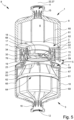
- Fig. 5 shows a longitudinal section through the container system 8 comprising the proposed connecting system 5 in a first connecting position.
- the first connecting arrangement 2 and the second connecting arrangement 4 are partially inserted into one another.
- the first connecting arrangement 2 can be locked to the second connecting arrangement 4, preferably in a non-detachable manner.
- the cutting edge 21 is at least partially opposite the frangible point 23, but does not yet separate it in the first connecting position shown in Fig. 5 .
- Fig. 6 shows a longitudinal section through the container system 8 comprising the proposed connecting system 5 in a second connecting position.
- this connecting position the cutting edge 21 of the first connecting arrangement 2 has penetrated the frangible point 23 of the second connecting arrangement 4.
- the first connecting arrangement 2 and the second connecting arrangement 4 have been further inserted into one another translationally, such that the cutting edge 21 has a separating effect on the frangible point 23 and has caused the mouth 19 of the second closure arrangement 4 to be opened or exposed.
- the coupling arrangement 17 and the mouth 19 are complementary to one another and are non-circular, in the example shown oval, in cross section perpendicularly to the coupling axis 22.
- a rotation of the connecting arrangements 2, 4 relative to one another about the coupling axis 22 brings about preferably elastic deformation of the coupling arrangement 17.
- the connecting arrangements 2, 4 are preferably rotatable between a first position, which corresponds to the position of the connecting arrangements 2, 4 after they have been translationally inserted into one another without rotation, and an end position.
- the connecting arrangements 2, 4 are preferably rotatable relative to one another by at least substantially 90 degrees.
- the rotation is partial, in particular approximately 60 degrees. This is sufficient to form a passage P of which the opening width is increased by means of further rotation and the associated deformation of the coupling arrangement 17.
- Fig. 7B shows a longitudinal section through a container system with the proposed connecting system and with the fluidic connection F made, according to which the connecting arrangements 2, 4 have been further rotated relative to one another or as far as a stop or up to an end position, in particular by approximately 90 degrees.
- the rotation causes the coupling arrangement 17 to have deformed such that the closure 18 has broken due to the distortion caused by the deformation and thereby has caused an opening in the first connecting arrangement 2.
- the opening width of the passage P is increased.
- the fluidic connection F or passage P has been formed by the opening in the first connecting arrangement 2.
- the contents of the interior 6 of the first container 1 can now reach the interior 7 of the second container 3, and vice versa. Accordingly, the contents can be mixed.
- first connecting arrangement 2 or the first container 1 comprising said connecting arrangement may be implemented independently of the second connecting arrangement 4.
- the proposed coupling arrangement 17 may then in principle be used in another connection for the cutting opening and/or may be used to make it possible to open the closure 18 by deformation of the coupling arrangement 17. It is clear that the combination of the first connecting arrangement 2 and the second connecting arrangement 4 corresponding thereto as the connecting system 5 is nevertheless particularly preferred.
- the cutting edge 21 is arranged at an open end 26 of the tubular coupling arrangement 17 like depicted in Fig. 1 . This is suitable for opening the second connecting arrangement by means of a translational relative movement of the connecting arrangements 2, 4 along a coupling axis 22, regardless of whether a second connecting arrangement 4 is also provided.
- the tubular coupling arrangement 17 comprises a tube axis 27, which preferably corresponds to the coupling axis 22.
- the tube axis 27 is preferably an axis of symmetry of the at least substantially tubular coupling arrangement 17.
- the coupling arrangement 17 may therefore be rotationally symmetrical about the tube axis 27 or the coupling axis 22.
- the coupling arrangement 17 is preferably non-circular in cross section perpendicularly to the coupling axis 22 or tube axis 27. In the example shown, the coupling arrangement 17 is oval with axial symmetry to the coupling axis 22 or tube axis 27.
- the coupling arrangement 17 preferably has at least one weakened region 28 which enables or facilitates deformation of the coupling arrangement 17 radially relative to the coupling axis 22.
- the first connecting arrangement 2 is preferably opened by the coupling arrangement 17 being deformed and by the closure 18, which is surrounded by the coupling arrangement 17, being opened.
- the torque required for rotating the connecting arrangements 2, 4 can be reduced and thus the ease of opening can be improved if deformability of the coupling arrangement 17 required for opening the first connecting arrangement 2 is made easier. In the present case, this is made possible in particular by the weakened region(s) 28.
- the coupling arrangement 17 preferably has sufficient stability, in particular in the coupling direction 17 along the coupling axis 22.
- easy deformability is nevertheless advantageously achieved radially relative to the coupling axis 22, and therefore easy opening is made possible.
- the weakened region(s) 28 is/are formed by one or more notches.
- the notches in the form of weakened regions 28 have proven to be particularly suitable.
- the one or more notches extend at least substantially in parallel with the coupling axis 22. This advantageously allows for weakening of the coupling arrangement 17 primarily in the radial direction, while sufficient stability remains in the coupling direction.
- the weakened region(s) 28 and in particular the notch or notches are preferably formed by a reduction in wall thickness in the radial direction with respect to the coupling axis 22.
- the notches are preferably formed on a radially outer side. Alternatively or additionally, however, notches may also be formed on an inner side.
- the weakened regions 28 thus preferably extend along a first portion 29 of the coupling arrangement 17 from the height of the closure 18 towards an open edge or the cutting edge 21 of the coupling arrangement 17.
- the weakened region(s) 28 extend(s) in an elongate and/or uninterrupted form as far as the cutting edge 21 and interrupt(s) the course of the cutting edge 21 that otherwise corresponds at least substantially to the course of the frangible point 23. In this way, a tooth-like structure of the cutting edge 21 can be formed.
- a plurality of notches distributed along a circumferential line or surface of the coupling arrangement 17 are provided in the form of weakened regions 28.
- a weakening of the coupling arrangement 17 with regard to radial deformation relative to the coupling axis 22 can be achieved at least substantially along the entire circumferential line or surface of the coupling arrangement 17.
- deformation of the coupling arrangement 17 along the entire circumferential line or surface is furthermore preferred in order to make it possible to securely open the closure 18. Therefore, the corresponding, at least substantially more uniform or equidistant distribution of the weakened regions 28 is also preferred.
- preferably more than 6, in particular more than 12 and/or less than 100, preferably less than 50 weakened regions 28 or notches are provided.
- Fig. 8 shows a longitudinal section through the proposed connecting system 5 in another embodiment in the first connecting position. In this figure, the step portion 30 is clearly visible. In addition, reference is made in particular to Fig. 1 .
- the tubular coupling arrangement 17 preferably comprises a step portion 30 that extends substantially radially or perpendicularly relative to the tube axis 27 and is arranged between the first portion 29 extending at least substantially in parallel with the tube axis 27 and a second portion 31 extending at least substantially in parallel with the tube axis 27.
- the first portion 29 preferably connects one end of the step portion 30 to the cutting edge 21.
- the second portion 31 in turn preferably connects the step portion 30 to a structure of other parts of the first connecting arrangement 2.
- the coupling arrangement 17 has a tubular shape, which has a step portion 30 which changes the diameter or the clear width of the coupling arrangement 17 between the first portion 29 and the second portion 31.
- the step portion 30 adapts the shape of the tubular coupling arrangement 17, which is non-circular in cross section, to a circular shape of the surrounding structure.
- the step portion 30 may be formed in one piece or in several pieces.
- the step portion is formed on opposite sides of the coupling axis 22 in an axially symmetrical, rotationally symmetrical and/or interrupted manner.
- the step portion 30 forms a bellows together with the portions 29, 31 of the coupling arrangement 17 adjacent thereto.
- a bellows is a structure that is airtight and is flexible by means of one or more folds. In the present case, the airtightness is achieved by an uninterrupted, continuous wall, which is formed by the coupling arrangement 17. Furthermore, the step portion 30 creates kinks relative to the adjacent portions 29, 31. In particular radial deformation of the coupling arrangement 17 is thereby facilitated.
- the coupling arrangement 17 is preferably non-circular in cross section, as a result of which it preferably has at least one first half-axis 32 having a minimum length and at least one second half-axis 33 having a maximum length which preferably intersect the coupling axis 22 and the tube axis 27, respectively, like shown in Fig. 3 .
- the step portion 30 has a greater extension in alignment with the first half-axis 32 than in alignment with the second half-axis 33. In this way, simpler radial deformability of the coupling arrangement 17 can be made possible.
- the pressing elements 39 have play relative to a side facing away from the outwardly facing circumferential sealing surface 38, as for example shown in Fig. 9 . Furthermore, it may be provided that the pressing elements 39 press the outwardly facing circumferential sealing surface 38 against the inwardly facing circumferential sealing surface 36 for a more secure sealing effect by exerting pressure on the sealing arrangement 34 on a side facing away from the outwardly facing circumferential sealing surface 38, at least after rotation of the connecting arrangements 2, 4 relative to one another for opening the first connecting arrangement 2 and/or the coupling arrangement 17, as for example shown in Fig. 10 .
- the coupling arrangement 17 preferably comprises the closure 18 in the form of a closure plate that is integrally formed with the coupling arrangement 17 and is connected to the coupling arrangement 17 by a frangible point or line of weakness, the frangible point or line of weakness being suitable for rupturing by deformation of the coupling arrangement 17 in order to form the passage P.
- the closure plate it is preferable for the closure plate to be inclined, specifically preferably both with respect to the coupling axis 22 and with respect to a plane perpendicular thereto, as for example shown in Fig. 1 . It has been found to be advantageous for the closure plate to be inclined, since, in this case, it tilts due to the deformation of the coupling arrangement 17 when rupturing a surrounding frangible point 23 and provides a sufficiently large opening.
- the closure plate 18' it is preferable for the closure plate 18' to extend at least substantially perpendicularly to the tube axis 27 and to comprise asymmetrically arranged reinforcing structures 57, in particular asymmetrically arranged stiffening ribs. Otherwise, the closure 18' preferably has the same or corresponding properties as the closure 18 of the first connecting arrangement 2.
- both the inclination of a closure plate and the asymmetrically arranged stiffening or weakening structures of such closure plate can be realized in combination, i.e., the same closure plate might combine them. Then, such closure plate does not extend at least substantially perpendicularly to the tube axis 27 as it is inclined.
- stiffening or weakening structures like stiffening ribs 72 might be arranged asymmetrically like those of the third connecting arrangement 45, as for example shown in Fig. 11 .
- the closure 18' formed as the closure plate preferably comprises reinforcing structures 57 which are asymmetrically distributed in a main direction of extension of the closure plate.
- reinforcing structures 57 are sometimes displaced with respect to a centre point or centre of gravity of the closure plate and sometimes are also only provided on one side with respect to a centre point or centre of gravity.
- the asymmetrical stability of the closure plate which results therefrom allows for secure opening under deformation of the coupling arrangement 17, in particular for smaller connecting arrangements 2, 4 or containers.
- the closure 18' formed as the closure plate of the third connecting arrangement 45 preferably comprises one or more gussets 58 at the edge.
- the gussets 58 are preferably arranged on radially opposite sides of the closure plate. They are preferably provided on or in the extension of the shorter half-axis 32 of a basically oval shape of the closure plate. In the region of the gusset 58, the oval basic shape of the closure plate is accordingly pierced and guided to the outside in the form of the gussets 58.
- the reinforcing structures 57 prefferably be arranged at least substantially mirror-symmetrically relative to an imaginary plane through an imaginary connecting line of the gussets 58 and a perpendicular line relative to the main plane of extension of the closure plate.
- the reinforcing structures 57 are preferably rib-like or formed by ribs.
- the reinforcing structures 57 are preferably primarily arranged on a side facing one of the gussets 58.
- the containers 1, 3 comprise a container blank 9, 10 and the first connecting arrangement 2 or second connecting arrangement 4, which can be inserted into one another by means of an insertion movement.
- the relevant container blank 9, 10 and the relevant connecting arrangement 2, 4 preferably have form-fitting elements 59 that are formed to be complementary to one another and prevent the connecting arrangement 2, 4 and the container blank 9, 10 from rotating relative to one another by means of a form fit when said connecting arrangement is inserted into said container blank.
- the form-fitting elements 59 are preferably formed by recesses and corresponding protrusions, as for example shown by way of example in Fig. 3 and Fig. 4 , and form-fitting elements 59 that are complementary thereto are provided on the container blanks 9, 10.
- the form-fitting elements 59 bring about locking by means of an insertion movement of the container blank 9, 10 and a connecting arrangement 2, 4 into one another.
- the form-fitting elements 59 bring about teeth and/or a lock and/or a locking mechanism.
- the form-fitting elements 59 are preferably arranged on an inner, circumferential side wall of the container blank 9, 10 and on an outer, circumferential side wall of the connecting arrangement 2, 4.
- a position of the container blank 9, 10 relative to the connecting arrangement 2, 4 is predetermined and/or a form fit is formed which prevents the container blank 9, 10 and the connecting arrangement 2, 4 from rotating relative to one another.
- the container blank 9, 10 and the connecting arrangement 2, 4 may be inserted into one another by means of an insertion movement, the container blank 9, 10 preferably comprising rib-like stiffening structures 60, in particular one or more ribs.
- the stiffening structures 60 in turn preferably comprise open ends 61 and the connecting arrangement 2, 4 comprises coupling structures 62 that are formed to be complementary thereto, engage in one another when the connecting arrangement 2, 4 is inserted into the container blank 9, 10, and prevent any rotation relative to one another by means of a form fit. This is shown by way of example in Figs. 1 and 2 .
- the coupling structures 62 are preferably formed by recesses corresponding to the open ends 61 of the stiffening structures 60.
- the coupling structures 62 together with the stiffening structures 60 preferably bring about locking by means of an insertion movement of the container blank 9, 10 and a connecting arrangement 2, 4 into one another.
- the coupling structures 62 together with the stiffening structures 60 form teeth, an at least partially toothing and/or a lock and/or a locking mechanism.
- the open ends 61 of the stiffening structures 60 engage into the coupling structures 62 at least essentially axially, like depicted for example in Fig. 1 .
- This axial engagement between the open ends 61 of the stiffening structures 60 and the coupling structures 62 may also provide a means for positively positioning the connecting arrangement 2,4 into the container blank 9,10 along the tube axis 27.
- the open ends 61 of the stiffening structures 60 engage into the coupling structures 62 at least essentially radially, as depicted for example in Fig. 2 .
- the open ends 61 of the stiffening structures 60 preferably radially engage behind the coupling structures 62 for positively locking the outer wall 63.
- the open ends 61 can engage the coupling structures 62 preventing the (second) connecting arrangement 4 from rotation relative to its container blank 10 or not.
- rotation is prevented by means of form-fitting element 59 of the (second) connecting arrangement 4.
- the present invention relates to the production of a container 1, 3 from a container blank 9, 10 and a connecting arrangement 2, 3, it being possible for the container blank 9, 10 and the (relevant) connecting arrangement to be inserted into one another by means of an insertion movement, and the container blank 9, 10 preferably comprising rib-like stiffening structures 60, the stiffening structures 60 comprising open ends and the connecting arrangement 2, 4 comprising coupling structures 62 that are formed to be complementary or partially complementary thereto, and the container blank 9, 10 and the connecting arrangement 2, 4 being inserted into one another by means of an insertion movement, as a result of which the open ends and the coupling structures 62 engage in one another, such that the container blank 9, 10 and the connecting arrangement 2, 4 are prevented from rotating relative to one another and/or a position of the container blank 9, 10 relative to the connecting arrangement 2, 4 is predetermined during the insertion.
- the first and/or second connecting arrangement 2, 4 comprises an offset 77 between the closure 20 and the coupling arrangement 17 and a circumferential outer wall 63, the offset 77 being stiffened by one or more ribs 67.
- the ribs are preferably arranged on a side facing the interior of the container 1 in the assembled state.
- the ribs preferably extend at least substantially radially relative to the tube axis 27 or coupling axis 22 and/or at least substantially along the entire offset 77.
- the first connecting arrangement 2 has an offset, which can also be stiffened by ribs (not shown).
- the container blank 9, 10 preferably comprises a bottle neck 15, 16 that opens into a removal opening 11, 12 and a circumferential outer wall of the container blank 9, 10 which connects the bottle neck 15, 16 to an open tubular end 64 provided on the side facing away from the bottle neck 15, 16, for inserting the connecting arrangement 2, 4.
- the container blank 9, 10 comprises one or more stiffening structures 60 in the form of ribs for stiffening its outer wall which extend at least substantially from the bottle neck 15, 16 in the direction of the open end 61.
- the one or more ribs may form a stop for the connecting arrangement such that they determine how far the connecting arrangement 2, 4 can be inserted into the container blank 9, 10.
- the one or more ribs are preferably arranged on a side of the outer wall of the container blank 9, 10 facing the interior of the container blank 9, 10.
- the one or more ribs may openly project into the interior of the container blank 9, 10.
- the one or more ribs may comprise, on an end 61 facing away from the bottle neck 15, 16, an end portion 65 spaced apart from the outer wall of the container blank 9, 10 for engaging in a coupling structure 62 formed by a recess in the connecting arrangement 2, 4.
- the tubular coupling arrangement 17 preferably comprises a circumferential wall 66, in particular formed by the first portion 29, the second portion 31 and/or the step portion 30.
- the circumferential wall 66 of the tubular coupling arrangement 17 preferably comprises one or more ribs 67 and/or folded structures 68 for stiffening the tubular coupling arrangement 17 in the direction of the tube axis 27 or coupling axis 22.
- Fig. 15 is a cross section through the first connecting arrangement 2 perpendicularly to the coupling axis 22 in the direction of the container 1 behind the closure 18, in which the ribs 67 and/or folded structures 68 can be seen.
- the ribs 67 and/or folded structures 68 are preferably elongated, with a main extension extending in the direction of the tube axis 27 or coupling axis 22.
- the ribs 67 and/or folded structures 68 are preferably formed integrally with the wall 66.
- the preferably circumferential wall 66 of the tubular coupling arrangement 17 preferably has a radius 69 that increases starting from an open end or the cutting edge 21.
- the increasing radius 69 is preferably formed by an inclined step and/or a conical jacket portion. In this regard, reference is additionally made to Figs. 8 and 11 .
- the step and/or the conical jacket portion may be inclined relative to the tube axis 27 or coupling axis 22 at an angle 70.
- the step and/or the conical jacket portion preferably encloses an angle 70 of preferably more than 15 degrees and/or less than 75 degrees together with the tube axis 27.
- the angle 70 is preferably obtuse relative to adjacent portions of the tubular coupling arrangement 17 or the first portion 29 thereof which has the cutting edge 21.
- the radius 69 which is smaller in the region of the cutting edge 21 and increases therefrom, preferably forms an insertion aid.
- the closure 20 of the second connecting arrangement 4 is preferably formed by a closure plate. This is particularly preferably delimited by a frangible point 23 in the form of a fragile line of weakness and additionally comprises an in particular structurally weakened region.
- the closure 20 preferably has a centrally arranged stiffening 74 that is surrounded by the weakened region 73.
- the closure 20 preferably comprises a frame 75 that connects the line of weakness to the weakened region 73.
- Closure caps corresponding to the first and/or second connecting arrangement 2, 4 may correspond, with the same or similar function, to the first and/or second connecting arrangement 2, 4 when adapted accordingly.
- the third connecting arrangement 45 preferably corresponds to the first connecting arrangement 2, or vice versa.
- the fourth connecting arrangement 46 preferably corresponds to the second connecting arrangement 4, or vice versa.
- the relevant closure cap 55, 56 and the relevant connecting arrangement 45, 46 comprise mutually corresponding guide surfaces 76.
- the guide surfaces 76 have an incline relative to one another by means of which, when the closure cap 55, 56 rotates relative to the connecting arrangement 2, 4, a force that separates the closure cap 55, 56 from the connecting arrangement 2, 4 is generated.
- the closure cap 55 comprises a wall which has an incline at an open edge
- the connecting arrangement 2, 45 comprises a sliding surface which corresponds to the edge and against which the edge is supported when the closure cap rotates relative to the connecting arrangement with its incline, or vice versa.
- the first connecting arrangement 2 or the coupling arrangement 17 is particularly advantageous if it both comprises one or more weakened regions 28 and additionally comprises the folded structure 68, preferably on a side facing away from the cutting edge 21.
- the weakened region(s) 28 can thus be arranged in the first portion 29 of the coupling arrangement 17, while the folded structure 68 is implemented in the second portion 31 of the coupling arrangement 17.
- stability of the coupling arrangement 17 is maintained in the direction of the coupling axis 22, while radial deformability is further improved overall.
- the first portion 29 for stabilizing the cutting edge 21 may have a greater wall thickness than the second portion 31 comprising the folded structure 68. Therefore, overall, material savings, a stable cutting edge 21 and the improved radial deformability are achieved in combination.
- the folded structure 68 and/or the weakened region(s) 28 are further combined with the step portion 30, in any case in portions along the circumferential line / surface of the coupling arrangement 17.
- the step portion 30 may be provided between the first portion 29 and the second portion 31 of the coupling arrangement 17 or between the region comprising the weakened region(s) 28 and the region comprising the folded structure 68.
- This combination has proven to be particularly advantageous in order to achieve particularly simple radial formability with sufficient axial stability as a result, such that, during the coupling of the first connecting arrangement 2 to the second connecting arrangement 4, the cutting edge 21 can cut open the frangible point 23 of the closure 18 to form the mouth 19, while the subsequent radial deformation of the coupling arrangement 17 can be achieved particularly easily, i.e. with relatively low torques.
- the step portion 30 (in the direction of the coupling axis 22) is smaller behind a projecting tip of the cutting edge 21 than in other regions, or is not present. In this way, the stability of the coupling arrangement 17 can be improved in the region in which the cutting edge 21 first and/or primarily acts on the frangible point 23.
- bayonet elements 51-54 which may comprise one or more guide surfaces 76 in order to cause the closure caps 55, 56 to be levered off when one of said closure caps is rotated.
- the bayonet elements 51-54 have a certain radial extension for the function of the bayonet catches 47-50. This radial expansion produces an end face that faces outwards or faces away from the interior 6, 7, which may be advantageously used without additional use of material to form the guide surface 76.
- FIG. 17 to 20 show an alternative embodiment of the connecting arrangement 46 according to Fig. 13 and the corresponding closure cap 56 according to Fig. 14 .
- the connecting arrangement 46 according to Fig. 13 and the corresponding closure cap 56 according to Fig. 14 .
- the focus is merely on the aspects which differ from the fourth connecting arrangement 46 and its closure cap 56 according to Fig. 13 and 14 .
- the same reference numbers are used for similar parts.
- the connecting arrangement 46 according to Fig. 17 has a higher diameter compared to the connecting arrangement 46 according to Fig. 13 .
- the closure cap 56 according to Fig. 18 has a corresponding diameter being higher than that of closure cap 56 depicted in Fig. 14 accordingly.
- This is achieved by constructional elements adapting functional parts to the higher diameter and/or scaling.
- the in the following discussed features can be applied to different diameters and, in particular, to the embodiment according to Fig. 13 and 14 as well.
- the connecting arrangement 46 comprises a first blocking element 78.
- This blocking element 78 can be configured to form a reversible/non-permanent lock, preferably snap-lock, with a second blocking element 79 of the closure cap 56 depicted in Fig. 18 .
- the lock provided by the combination of preferably engaging blocking elements 78, 79 preferably is reversible, i.e., can be released upon applying sufficient torque to the closure cap 56 relative to the connecting arrangement 46.
- the first blocking element 78 is or comprises an opening, preferably opening in a radially inward direction, while the second blocking element 79 is or comprises a complementary structure for engaging the first blocking element 78 when the closure cap 56 is mounted on the connecting arrangement 46 (completely/until stop).
- FIG. 19 the connecting arrangement 46 and its corresponding closure cap 56 are shown in a position where the closure cap 56 is moved away from the connecting arrangement 46 such that based on the depicted partial cut of the closure cap 56 both blocking elements 78, 79 are visible, here are in a disengaged position.
- Fig. 20 which shows a cross-section of the combination of the connecting arrangement 46 and its closure cap 56 along a cutting plane which is moved slightly radially inwardly based on the cutting plane used for the partial cut depicted in Fig. 19 , the closure cap 56 is not anymore moved away from the connecting arrangement 46, but is snap-locked to or held otherwise at the connecting arrangement 46 (up to stop). Accordingly, the blocking elements 78, 79 engage as can be seen in Fig. 20 .
- the first blocking element 78 of the connecting arrangement 46 is or comprises a recess formed by walls attached to or formed with an inner surface of the connecting arrangement/extend in a radially inward direction such that the recess is accessible in a radially outwardly direction.
- the first blocking element 78 and/or the second blocking element 79 can have weak structures that enable deformation in order to facilitate disengagement of the blocking elements 78, 79 upon sufficient torque.
- the second blocking element 79 of the closure cap 56 in the embodiment shown comprises a protrusion like a bead or latch for extending into the first blocking element 78, thus causing engagement of the blocking elements 78, 79.
- the protrusion extends essentially in a radially outward direction.
- the structure of the blocking elements 78, 79 can be exchanged and the same or at least a similar effect can be obtained. Further, different realizations may be applied in order to arrive at the function of the first and second blocking elements 78, 79.
- the connecting arrangement 46 and the closure cap 56 preferably each comprise at least one, in the embodiment shown two blocking elements 78, 79. Those blocking elements in the embodiment shown are arranged on opposite sides relative to the coupling axis 22/ tube axis 27. At least or more than two blocking elements 78, 79 on each the connecting arrangement 46 and the closure cap 56 can be provided accordingly on respectively corresponding positions such that corresponding blocking elements 78, 79 preferably engage and disengage simultaneously.
Landscapes
- Health & Medical Sciences (AREA)
- Veterinary Medicine (AREA)
- Public Health (AREA)
- Pharmacology & Pharmacy (AREA)
- Life Sciences & Earth Sciences (AREA)
- Animal Behavior & Ethology (AREA)
- General Health & Medical Sciences (AREA)
- Engineering & Computer Science (AREA)
- Physics & Mathematics (AREA)
- Fluid Mechanics (AREA)
- Mechanical Engineering (AREA)
- Ceramic Engineering (AREA)
- Medical Preparation Storing Or Oral Administration Devices (AREA)
- Stackable Containers (AREA)
- Quick-Acting Or Multi-Walled Pipe Joints (AREA)
- Closures For Containers (AREA)
Claims (13)
- Verbindungsanordnung (2) für ein Verbindungssystem (5) zur Herstellung einer fluidischen Verbindung (F) zwischen einem ersten Behälter (1) und einem zweiten Behälter (3), wobei zur Herstellung der fluidischen Verbindung (F) die Verbindungsanordnung (2) mit einer zweiten Verbindungsanordnung (4) koppelbar ist und das Verbindungssystem (5) dazu ausgebildet ist, durch Kopplung eine Öffnung zu bewirken, wodurch eine Passage (P) erzeugt wird, die geeignet ist, die Innenräume (6, 7) der Behälter (1, 3) miteinander zu verbinden,wobei die Verbindungsanordnung (2) eine rohrförmige Kopplungsanordnung (17) mit einer Rohrachse (27) aufweist, wobei die Kopplungsanordnung (17) in einem Urpsrungszustand geschlossen ist und zur Bildung der Passage (P) durch Verformung der Kopplungsanordnung (17) quer zu ihrer Rohrachse (27) öffenbar ist,dadurch gekennzeichnet, dassdie Kopplungsanordnung (17) einen sich im Wesentlichen radial zur Rohrachse (27) erstreckenden Stufenabschnitt (30) aufweist, der zwischen einem ersten, zumindest im Wesentlichen parallel zur Rohrachse (27) verlaufenden Abschnitt (29) und einen zweiten, zumindest im Wesentlichen parallel zur Rohrachse (27) verlaufenden Abschnitt (31) angeordnet ist, undder Stufenabschnitt (30) mit der Kopplungsanordnung (17) einen Balg bildet.
- Verbindungsanordnung nach Anspruch 1, dadurch gekennzeichnet, dass die Kopplungsanordnung (17) im Querschnitt nicht-kreisförmig ist, wodurch sie mindestens eine erste Halbachse (32) mit einer minimalen Länge und mindestens eine zweite Halbachse (33) mit einer maximalen Länge aufweist, und der Stufenabschnitt (30) in Flucht mit oder in Verlängerung der ersten Halbachse (32) eine größere Erstreckung aufweist als in Flucht mit der zweiten Halbachse (33).
- Verbindungsanordnung nach Anspruch 2, dadurch gekennzeichnet, dass der Stufenabschnitt (30) in Flucht mit oder in Verlängerung der ersten Halbachse (32) einen Balg bildet.
- Verbindungsanordnung nach Anspruch 2 oder 3, dadurch gekennzeichnet, dass sich der Stufenabschnitt (30) in Richtung der Flucht mit der zweiten Halbachse (33) verjüngt.
- Verbindungsanordnung nach Anspruch 4, dadurch gekennzeichnet, dass der Stufenabschnitt (30) sich in Richtung der Flucht mit oder in Verlängerung der zweiten Halbachse (33) bis auf Null verjüngt, so dass in Flucht mit der zweiten Halbachse kein Stufenabschnitt (30) vorgesehen ist.
- Verbindungsanordnung nach einem der Ansprüche 2 bis 5, dadurch gekennzeichnet, dass die radiale Erstreckung des Stufenabschnitts (30) ausgehend von der Flucht mit oder in Verlängerung der zweiten Halbachse (33) beidseitig in Richtung der Flucht mit oder in der Verlängerung der ersten Halbachse (32), insbesondere stetig, zunimmt.
- Verbindungsanordnung nach einem der vorhergehenden Ansprüche, dadurch gekennzeichnet, dass der Stufenabschnitt (30) die im Querschnitt nicht-kreisförmige Form der Kopplungsanordnung (17) auf eine kreisrunde Form adaptiert.
- Verbindungsanordnung nach einem der vorhergehenden Ansprüche, dadurch gekennzeichnet, dass der Stufenabschnitt (30) einen Rohrabschnitt mit kreisrundem Querschnitt mit der im Querschnitt nicht-kreisförmigen Kopplungsanordnung (17) verbindet.
- Verbindungsanordnung nach einem der vorhergehenden Ansprüche, dadurch gekennzeichnet, dass der Stufenabschnitt (30) zumindest im Wesentlichen in einer Ebene liegt, die senkrecht zur Kopplungsrichtung (17) steht.
- Verbindungsanordnung nach einem der vorhergehenden Ansprüche, dadurch gekennzeichnet, dass sich der Stufenabschnitt (30) zwischen einer Ovalrohr-Außenfläche der Kopplungsanordnung (17) und einem Rundrohrabschnitt radial zur Kopplungsanordnung (17) erstreckt.
- Verbindungsanordnung nach einem der vorhergehenden Ansprüche, dadurch gekennzeichnet, dass der Stufenabschnitt (30) den Durchmesser oder die lichte Weite der Kopplungsanordnung (17) zwischen dem ersten Abschnitt (29) und dem zweiten Abschnitt (31) verändert.
- Verbindungssystem (2) zur Herstellung einer fluidischen Verbindung zwischen einem ersten Behälter (1) und einem zweiten Behälter (3), wobei das Verbindungssystem (5) eine Verbindungsanordnung (2) nach einem der vorhergehenden Ansprüche und eine zweite Verbindungsanordnung (4) aufweist, wobei die erste Verbindungsanordnung (2) und die zweite Verbindungsanordnung (4) miteinander koppelbar sowie dazu ausgebildet sind, durch Kopplung eine Öffnung zu bewirken, wodurch eine Passage (P) erzeugt wird, die geeignet ist, die Innenräume (6, 7) der Behälter (1, 3) miteinander zu verbinden.
- Behältersystem (8) aufweisend einen ersten Behälter (1) und einen zweiten Behälter (3), wobei das Behältersystem (8) das Verbindungssystem nach Anspruch 12 aufweist, wobei der erste Behälter (1) die erste Verbindungsanordnung (2) und der zweite Behälter (3) die zweite Verbindungsanordnung (4) aufweist, und wobei der erste Behälter (1) mit dem zweiten Behälter (3) mittels der ersten Verbindungsanordnung (2) und der zweiten Verbindungsanordnung (3) miteinander koppelbar sowie dazu ausgebildet sind, durch Kopplung eine Öffnung zu bewirken, wodurch eine Passage (P) zwischen den Innenräumen (6, 7) der Behälter (1, 3) erzeugt wird, der die Innenräume (6, 7) der Behälter (1, 3) miteinander verbindet.
Priority Applications (3)
| Application Number | Priority Date | Filing Date | Title |
|---|---|---|---|
| EP25185523.5A EP4617198A3 (de) | 2020-01-24 | 2021-01-21 | Verbindungsanordnung, verbindungssystem, behälter und behältersystem |
| EP25185535.9A EP4600176A3 (de) | 2020-01-24 | 2021-01-21 | Verbindungsanordnung, verbindungssystem, behälter und behältersystem |
| EP25185529.2A EP4617199A3 (de) | 2020-01-24 | 2021-01-21 | Verbindungsanordnung, verbindungssystem, behälter und behältersystem |
Applications Claiming Priority (2)
| Application Number | Priority Date | Filing Date | Title |
|---|---|---|---|
| EP20153582 | 2020-01-24 | ||
| PCT/EP2021/051324 WO2021148531A1 (en) | 2020-01-24 | 2021-01-21 | Connecting arrangement, connecting system, container and container system |
Related Child Applications (3)
| Application Number | Title | Priority Date | Filing Date |
|---|---|---|---|
| EP25185529.2A Division EP4617199A3 (de) | 2020-01-24 | 2021-01-21 | Verbindungsanordnung, verbindungssystem, behälter und behältersystem |
| EP25185535.9A Division EP4600176A3 (de) | 2020-01-24 | 2021-01-21 | Verbindungsanordnung, verbindungssystem, behälter und behältersystem |
| EP25185523.5A Division EP4617198A3 (de) | 2020-01-24 | 2021-01-21 | Verbindungsanordnung, verbindungssystem, behälter und behältersystem |
Publications (3)
| Publication Number | Publication Date |
|---|---|
| EP4093361A1 EP4093361A1 (de) | 2022-11-30 |
| EP4093361B1 true EP4093361B1 (de) | 2025-07-02 |
| EP4093361C0 EP4093361C0 (de) | 2025-07-02 |
Family
ID=69191956
Family Applications (4)
| Application Number | Title | Priority Date | Filing Date |
|---|---|---|---|
| EP25185535.9A Pending EP4600176A3 (de) | 2020-01-24 | 2021-01-21 | Verbindungsanordnung, verbindungssystem, behälter und behältersystem |
| EP25185523.5A Pending EP4617198A3 (de) | 2020-01-24 | 2021-01-21 | Verbindungsanordnung, verbindungssystem, behälter und behältersystem |
| EP21701503.1A Active EP4093361B1 (de) | 2020-01-24 | 2021-01-21 | Verbindungsanordnung, verbindungssystem, behälter und behältersystem |
| EP25185529.2A Pending EP4617199A3 (de) | 2020-01-24 | 2021-01-21 | Verbindungsanordnung, verbindungssystem, behälter und behältersystem |
Family Applications Before (2)
| Application Number | Title | Priority Date | Filing Date |
|---|---|---|---|
| EP25185535.9A Pending EP4600176A3 (de) | 2020-01-24 | 2021-01-21 | Verbindungsanordnung, verbindungssystem, behälter und behältersystem |
| EP25185523.5A Pending EP4617198A3 (de) | 2020-01-24 | 2021-01-21 | Verbindungsanordnung, verbindungssystem, behälter und behältersystem |
Family Applications After (1)
| Application Number | Title | Priority Date | Filing Date |
|---|---|---|---|
| EP25185529.2A Pending EP4617199A3 (de) | 2020-01-24 | 2021-01-21 | Verbindungsanordnung, verbindungssystem, behälter und behältersystem |
Country Status (7)
| Country | Link |
|---|---|
| US (1) | US20230113868A1 (de) |
| EP (4) | EP4600176A3 (de) |
| CN (1) | CN115209857A (de) |
| ES (1) | ES3040549T3 (de) |
| HU (1) | HUE073100T2 (de) |
| TW (1) | TW202206048A (de) |
| WO (1) | WO2021148531A1 (de) |
Families Citing this family (1)
| Publication number | Priority date | Publication date | Assignee | Title |
|---|---|---|---|---|
| EP4476144A4 (de) * | 2021-12-21 | 2026-03-25 | Haleon Us Holdings Llc | Verbundenes behältersystem |
Family Cites Families (19)
| Publication number | Priority date | Publication date | Assignee | Title |
|---|---|---|---|---|
| FR2666305B1 (fr) * | 1990-09-05 | 1992-11-13 | Oreal | Dispositif pour conserver separes l'un de l'autre au moins deux produits et pour effectuer leur melange au moment de l'utilisation. |
| IT227015Y1 (it) * | 1992-11-27 | 1997-09-09 | Ibsa Inst Biochimique Sa | Dispositivo dosatore per sciroppi estemporanei multidose ad uso farmaceutico |
| US5769215A (en) * | 1994-03-22 | 1998-06-23 | Georg Wiegner | Two-component package |
| TW453329U (en) * | 2000-08-01 | 2001-09-01 | Shiu Li Li | Container device with separating storage structure |
| JP2008514514A (ja) * | 2004-10-01 | 2008-05-08 | ベルキャップ エージー | カプセル・クロージャー |
| CA2593022C (en) * | 2004-12-09 | 2013-11-26 | Hee Kwon Rho | Vessel cap and system for manufacturing the same |
| WO2007134392A2 (en) * | 2006-05-19 | 2007-11-29 | Cinch Pak Pty Ltd | Storage device for selectively adding substance to a liquid |
| US8366676B2 (en) * | 2006-11-02 | 2013-02-05 | Becton, Dickinson And Company | Vascular access device gas displacement |
| EP1944248B1 (de) * | 2007-01-15 | 2017-12-13 | Swiss Caffe Asia Ltd. | Kapsel, Mittel zum Penetrieren des Bodens einer Kapsel und Vorrichtung für die Zubereitung eines Getränks |
| US8216207B2 (en) * | 2007-08-01 | 2012-07-10 | Hospira, Inc. | Medicament admixing system |
| GB201005812D0 (en) * | 2010-04-07 | 2010-05-26 | Entpr Cradle The Ltd | Connector system for medical fluid administration |
| EP2651366B1 (de) * | 2010-12-14 | 2016-06-08 | Hoffmann Neopac AG | Tubus mit weiblichem luer-lock-anschluss |
| WO2013104550A1 (de) | 2012-01-13 | 2013-07-18 | Boehringer Ingelheim Vetmedica Gmbh | Kit zur herstellung eines impfstoffs |
| US9339439B2 (en) * | 2012-09-07 | 2016-05-17 | P. J. Nudo | Pharmaceutical container system |
| MX2017016558A (es) | 2015-06-16 | 2018-05-11 | Boehringer Ingelheim Vetmedica Gmbh | Sistema de conexion y de recipiente. |
| UA125578C2 (uk) * | 2015-06-16 | 2022-04-27 | Бьорінгер Інгельхайм Ветмедіка Гмбх | Система ємностей і їх з'єднання |
| AR110370A1 (es) * | 2016-12-16 | 2019-03-20 | Boehringer Ingelheim Vetmedica Gmbh | Sistema de recipientes y método |
| JP7050894B2 (ja) * | 2017-07-11 | 2022-04-08 | ベーリンガー インゲルハイム フェトメディカ ゲーエムベーハー | 容器システム |
| EP3784594B1 (de) * | 2018-04-25 | 2024-04-03 | Compagnie Gervais Danone | Mehrkammerbehälter mit einer schnittstellenvorrichtung zum mischen von inhalten und verfahren zur herstellung solch eines behälters |
-
2021
- 2021-01-21 EP EP25185535.9A patent/EP4600176A3/de active Pending
- 2021-01-21 EP EP25185523.5A patent/EP4617198A3/de active Pending
- 2021-01-21 ES ES21701503T patent/ES3040549T3/es active Active
- 2021-01-21 US US17/792,269 patent/US20230113868A1/en active Pending
- 2021-01-21 WO PCT/EP2021/051324 patent/WO2021148531A1/en not_active Ceased
- 2021-01-21 EP EP21701503.1A patent/EP4093361B1/de active Active
- 2021-01-21 TW TW110102301A patent/TW202206048A/zh unknown
- 2021-01-21 EP EP25185529.2A patent/EP4617199A3/de active Pending
- 2021-01-21 HU HUE21701503A patent/HUE073100T2/hu unknown
- 2021-01-21 CN CN202180010603.8A patent/CN115209857A/zh active Pending
Also Published As
| Publication number | Publication date |
|---|---|
| EP4617198A2 (de) | 2025-09-17 |
| WO2021148531A1 (en) | 2021-07-29 |
| EP4617199A2 (de) | 2025-09-17 |
| EP4617198A3 (de) | 2025-12-10 |
| TW202206048A (zh) | 2022-02-16 |
| ES3040549T3 (en) | 2025-11-03 |
| CN115209857A (zh) | 2022-10-18 |
| EP4600176A3 (de) | 2025-10-29 |
| EP4600176A2 (de) | 2025-08-13 |
| HUE073100T2 (hu) | 2025-12-28 |
| US20230113868A1 (en) | 2023-04-13 |
| EP4617199A3 (de) | 2025-12-10 |
| EP4093361C0 (de) | 2025-07-02 |
| EP4093361A1 (de) | 2022-11-30 |
Similar Documents
| Publication | Publication Date | Title |
|---|---|---|
| JP7530947B2 (ja) | 接続及び容器システム | |
| AU2022202467B2 (en) | Connecting and container system | |
| JP7426329B2 (ja) | 接続及び容器システム | |
| EP4093361B1 (de) | Verbindungsanordnung, verbindungssystem, behälter und behältersystem | |
| NZ776268B2 (en) | Connecting and container system | |
| NZ776269B2 (en) | Connecting and container system | |
| NZ776267B2 (en) | Connecting and container system | |
| NZ776806B2 (en) | Connecting and container system | |
| NZ777038B2 (en) | Connecting and container system |
Legal Events
| Date | Code | Title | Description |
|---|---|---|---|
| STAA | Information on the status of an ep patent application or granted ep patent |
Free format text: STATUS: UNKNOWN |
|
| STAA | Information on the status of an ep patent application or granted ep patent |
Free format text: STATUS: THE INTERNATIONAL PUBLICATION HAS BEEN MADE |
|
| PUAI | Public reference made under article 153(3) epc to a published international application that has entered the european phase |
Free format text: ORIGINAL CODE: 0009012 |
|
| STAA | Information on the status of an ep patent application or granted ep patent |
Free format text: STATUS: REQUEST FOR EXAMINATION WAS MADE |
|
| 17P | Request for examination filed |
Effective date: 20220609 |
|
| AK | Designated contracting states |
Kind code of ref document: A1 Designated state(s): AL AT BE BG CH CY CZ DE DK EE ES FI FR GB GR HR HU IE IS IT LI LT LU LV MC MK MT NL NO PL PT RO RS SE SI SK SM TR |
|
| DAV | Request for validation of the european patent (deleted) | ||
| DAX | Request for extension of the european patent (deleted) | ||
| GRAP | Despatch of communication of intention to grant a patent |
Free format text: ORIGINAL CODE: EPIDOSNIGR1 |
|
| STAA | Information on the status of an ep patent application or granted ep patent |
Free format text: STATUS: GRANT OF PATENT IS INTENDED |
|
| INTG | Intention to grant announced |
Effective date: 20250128 |
|
| GRAS | Grant fee paid |
Free format text: ORIGINAL CODE: EPIDOSNIGR3 |
|
| GRAA | (expected) grant |
Free format text: ORIGINAL CODE: 0009210 |
|
| STAA | Information on the status of an ep patent application or granted ep patent |
Free format text: STATUS: THE PATENT HAS BEEN GRANTED |
|
| AK | Designated contracting states |
Kind code of ref document: B1 Designated state(s): AL AT BE BG CH CY CZ DE DK EE ES FI FR GB GR HR HU IE IS IT LI LT LU LV MC MK MT NL NO PL PT RO RS SE SI SK SM TR |
|
| REG | Reference to a national code |
Ref country code: GB Ref legal event code: FG4D |
|
| REG | Reference to a national code |
Ref country code: CH Ref legal event code: EP |
|
| REG | Reference to a national code |
Ref country code: DE Ref legal event code: R096 Ref document number: 602021033277 Country of ref document: DE |
|
| REG | Reference to a national code |
Ref country code: IE Ref legal event code: FG4D |
|
| U01 | Request for unitary effect filed |
Effective date: 20250723 |
|
| U07 | Unitary effect registered |
Designated state(s): AT BE BG DE DK EE FI FR IT LT LU LV MT NL PT RO SE SI Effective date: 20250729 |
|
| REG | Reference to a national code |
Ref country code: ES Ref legal event code: FG2A Ref document number: 3040549 Country of ref document: ES Kind code of ref document: T3 Effective date: 20251103 |
|
| REG | Reference to a national code |
Ref country code: HU Ref legal event code: AG4A Ref document number: E073100 Country of ref document: HU |
|
| PG25 | Lapsed in a contracting state [announced via postgrant information from national office to epo] |
Ref country code: IS Free format text: LAPSE BECAUSE OF FAILURE TO SUBMIT A TRANSLATION OF THE DESCRIPTION OR TO PAY THE FEE WITHIN THE PRESCRIBED TIME-LIMIT Effective date: 20251102 |
|
| PG25 | Lapsed in a contracting state [announced via postgrant information from national office to epo] |
Ref country code: NO Free format text: LAPSE BECAUSE OF FAILURE TO SUBMIT A TRANSLATION OF THE DESCRIPTION OR TO PAY THE FEE WITHIN THE PRESCRIBED TIME-LIMIT Effective date: 20251002 |
|
| PG25 | Lapsed in a contracting state [announced via postgrant information from national office to epo] |
Ref country code: HR Free format text: LAPSE BECAUSE OF FAILURE TO SUBMIT A TRANSLATION OF THE DESCRIPTION OR TO PAY THE FEE WITHIN THE PRESCRIBED TIME-LIMIT Effective date: 20250702 |
|
| PG25 | Lapsed in a contracting state [announced via postgrant information from national office to epo] |
Ref country code: GR Free format text: LAPSE BECAUSE OF FAILURE TO SUBMIT A TRANSLATION OF THE DESCRIPTION OR TO PAY THE FEE WITHIN THE PRESCRIBED TIME-LIMIT Effective date: 20251003 |
|
| PG25 | Lapsed in a contracting state [announced via postgrant information from national office to epo] |
Ref country code: CZ Free format text: LAPSE BECAUSE OF FAILURE TO SUBMIT A TRANSLATION OF THE DESCRIPTION OR TO PAY THE FEE WITHIN THE PRESCRIBED TIME-LIMIT Effective date: 20250702 |
|
| PG25 | Lapsed in a contracting state [announced via postgrant information from national office to epo] |
Ref country code: PL Free format text: LAPSE BECAUSE OF FAILURE TO SUBMIT A TRANSLATION OF THE DESCRIPTION OR TO PAY THE FEE WITHIN THE PRESCRIBED TIME-LIMIT Effective date: 20250702 |
|
| PG25 | Lapsed in a contracting state [announced via postgrant information from national office to epo] |
Ref country code: RS Free format text: LAPSE BECAUSE OF FAILURE TO SUBMIT A TRANSLATION OF THE DESCRIPTION OR TO PAY THE FEE WITHIN THE PRESCRIBED TIME-LIMIT Effective date: 20251002 |
|
| PGFP | Annual fee paid to national office [announced via postgrant information from national office to epo] |
Ref country code: HU Payment date: 20260123 Year of fee payment: 6 |
|
| U20 | Renewal fee for the european patent with unitary effect paid |
Year of fee payment: 6 Effective date: 20260202 |
|
| PG25 | Lapsed in a contracting state [announced via postgrant information from national office to epo] |
Ref country code: SM Free format text: LAPSE BECAUSE OF FAILURE TO SUBMIT A TRANSLATION OF THE DESCRIPTION OR TO PAY THE FEE WITHIN THE PRESCRIBED TIME-LIMIT Effective date: 20250702 |
|
| PGFP | Annual fee paid to national office [announced via postgrant information from national office to epo] |
Ref country code: GB Payment date: 20260212 Year of fee payment: 6 |
|
| PGFP | Annual fee paid to national office [announced via postgrant information from national office to epo] |
Ref country code: ES Payment date: 20260227 Year of fee payment: 6 |