EP4093901B1 - Vorrichtung und verfahren zur kohlenstoffdioxid- oder kohlenstoffmonoxid-elektrolyse - Google Patents
Vorrichtung und verfahren zur kohlenstoffdioxid- oder kohlenstoffmonoxid-elektrolyse Download PDFInfo
- Publication number
- EP4093901B1 EP4093901B1 EP21715146.3A EP21715146A EP4093901B1 EP 4093901 B1 EP4093901 B1 EP 4093901B1 EP 21715146 A EP21715146 A EP 21715146A EP 4093901 B1 EP4093901 B1 EP 4093901B1
- Authority
- EP
- European Patent Office
- Prior art keywords
- anode
- electrolysis
- cell
- catalyst
- connection
- Prior art date
- Legal status (The legal status is an assumption and is not a legal conclusion. Google has not performed a legal analysis and makes no representation as to the accuracy of the status listed.)
- Active
Links
Images



Classifications
-
- C—CHEMISTRY; METALLURGY
- C25—ELECTROLYTIC OR ELECTROPHORETIC PROCESSES; APPARATUS THEREFOR
- C25B—ELECTROLYTIC OR ELECTROPHORETIC PROCESSES FOR THE PRODUCTION OF COMPOUNDS OR NON-METALS; APPARATUS THEREFOR
- C25B11/00—Electrodes; Manufacture thereof not otherwise provided for
- C25B11/02—Electrodes; Manufacture thereof not otherwise provided for characterised by shape or form
- C25B11/03—Electrodes; Manufacture thereof not otherwise provided for characterised by shape or form perforated or foraminous
- C25B11/031—Porous electrodes
-
- C—CHEMISTRY; METALLURGY
- C25—ELECTROLYTIC OR ELECTROPHORETIC PROCESSES; APPARATUS THEREFOR
- C25B—ELECTROLYTIC OR ELECTROPHORETIC PROCESSES FOR THE PRODUCTION OF COMPOUNDS OR NON-METALS; APPARATUS THEREFOR
- C25B1/00—Electrolytic production of inorganic compounds or non-metals
- C25B1/01—Products
- C25B1/23—Carbon monoxide or syngas
-
- C—CHEMISTRY; METALLURGY
- C25—ELECTROLYTIC OR ELECTROPHORETIC PROCESSES; APPARATUS THEREFOR
- C25B—ELECTROLYTIC OR ELECTROPHORETIC PROCESSES FOR THE PRODUCTION OF COMPOUNDS OR NON-METALS; APPARATUS THEREFOR
- C25B11/00—Electrodes; Manufacture thereof not otherwise provided for
- C25B11/02—Electrodes; Manufacture thereof not otherwise provided for characterised by shape or form
- C25B11/03—Electrodes; Manufacture thereof not otherwise provided for characterised by shape or form perforated or foraminous
- C25B11/031—Porous electrodes
- C25B11/032—Gas diffusion electrodes
-
- C—CHEMISTRY; METALLURGY
- C25—ELECTROLYTIC OR ELECTROPHORETIC PROCESSES; APPARATUS THEREFOR
- C25B—ELECTROLYTIC OR ELECTROPHORETIC PROCESSES FOR THE PRODUCTION OF COMPOUNDS OR NON-METALS; APPARATUS THEREFOR
- C25B11/00—Electrodes; Manufacture thereof not otherwise provided for
- C25B11/04—Electrodes; Manufacture thereof not otherwise provided for characterised by the material
- C25B11/051—Electrodes formed of electrocatalysts on a substrate or carrier
- C25B11/052—Electrodes comprising one or more electrocatalytic coatings on a substrate
-
- C—CHEMISTRY; METALLURGY
- C25—ELECTROLYTIC OR ELECTROPHORETIC PROCESSES; APPARATUS THEREFOR
- C25B—ELECTROLYTIC OR ELECTROPHORETIC PROCESSES FOR THE PRODUCTION OF COMPOUNDS OR NON-METALS; APPARATUS THEREFOR
- C25B11/00—Electrodes; Manufacture thereof not otherwise provided for
- C25B11/04—Electrodes; Manufacture thereof not otherwise provided for characterised by the material
- C25B11/051—Electrodes formed of electrocatalysts on a substrate or carrier
- C25B11/055—Electrodes formed of electrocatalysts on a substrate or carrier characterised by the substrate or carrier material
- C25B11/057—Electrodes formed of electrocatalysts on a substrate or carrier characterised by the substrate or carrier material consisting of a single element or compound
- C25B11/061—Metal or alloy
- C25B11/063—Valve metal, e.g. titanium
-
- C—CHEMISTRY; METALLURGY
- C25—ELECTROLYTIC OR ELECTROPHORETIC PROCESSES; APPARATUS THEREFOR
- C25B—ELECTROLYTIC OR ELECTROPHORETIC PROCESSES FOR THE PRODUCTION OF COMPOUNDS OR NON-METALS; APPARATUS THEREFOR
- C25B3/00—Electrolytic production of organic compounds
- C25B3/01—Products
- C25B3/03—Acyclic or carbocyclic hydrocarbons
-
- C—CHEMISTRY; METALLURGY
- C25—ELECTROLYTIC OR ELECTROPHORETIC PROCESSES; APPARATUS THEREFOR
- C25B—ELECTROLYTIC OR ELECTROPHORETIC PROCESSES FOR THE PRODUCTION OF COMPOUNDS OR NON-METALS; APPARATUS THEREFOR
- C25B3/00—Electrolytic production of organic compounds
- C25B3/20—Processes
- C25B3/25—Reduction
-
- C—CHEMISTRY; METALLURGY
- C25—ELECTROLYTIC OR ELECTROPHORETIC PROCESSES; APPARATUS THEREFOR
- C25B—ELECTROLYTIC OR ELECTROPHORETIC PROCESSES FOR THE PRODUCTION OF COMPOUNDS OR NON-METALS; APPARATUS THEREFOR
- C25B3/00—Electrolytic production of organic compounds
- C25B3/20—Processes
- C25B3/25—Reduction
- C25B3/26—Reduction of carbon dioxide
-
- C—CHEMISTRY; METALLURGY
- C25—ELECTROLYTIC OR ELECTROPHORETIC PROCESSES; APPARATUS THEREFOR
- C25B—ELECTROLYTIC OR ELECTROPHORETIC PROCESSES FOR THE PRODUCTION OF COMPOUNDS OR NON-METALS; APPARATUS THEREFOR
- C25B9/00—Cells or assemblies of cells; Constructional parts of cells; Assemblies of constructional parts, e.g. electrode-diaphragm assemblies; Process-related cell features
- C25B9/17—Cells comprising dimensionally-stable non-movable electrodes; Assemblies of constructional parts thereof
- C25B9/19—Cells comprising dimensionally-stable non-movable electrodes; Assemblies of constructional parts thereof with diaphragms
- C25B9/23—Cells comprising dimensionally-stable non-movable electrodes; Assemblies of constructional parts thereof with diaphragms comprising ion-exchange membranes in or on which electrode material is embedded
-
- C—CHEMISTRY; METALLURGY
- C25—ELECTROLYTIC OR ELECTROPHORETIC PROCESSES; APPARATUS THEREFOR
- C25B—ELECTROLYTIC OR ELECTROPHORETIC PROCESSES FOR THE PRODUCTION OF COMPOUNDS OR NON-METALS; APPARATUS THEREFOR
- C25B9/00—Cells or assemblies of cells; Constructional parts of cells; Assemblies of constructional parts, e.g. electrode-diaphragm assemblies; Process-related cell features
- C25B9/60—Constructional parts of cells
- C25B9/65—Means for supplying current; Electrode connections; Electric inter-cell connections
-
- C—CHEMISTRY; METALLURGY
- C25—ELECTROLYTIC OR ELECTROPHORETIC PROCESSES; APPARATUS THEREFOR
- C25B—ELECTROLYTIC OR ELECTROPHORETIC PROCESSES FOR THE PRODUCTION OF COMPOUNDS OR NON-METALS; APPARATUS THEREFOR
- C25B9/00—Cells or assemblies of cells; Constructional parts of cells; Assemblies of constructional parts, e.g. electrode-diaphragm assemblies; Process-related cell features
- C25B9/70—Assemblies comprising two or more cells
- C25B9/73—Assemblies comprising two or more cells of the filter-press type
-
- C—CHEMISTRY; METALLURGY
- C25—ELECTROLYTIC OR ELECTROPHORETIC PROCESSES; APPARATUS THEREFOR
- C25B—ELECTROLYTIC OR ELECTROPHORETIC PROCESSES FOR THE PRODUCTION OF COMPOUNDS OR NON-METALS; APPARATUS THEREFOR
- C25B9/00—Cells or assemblies of cells; Constructional parts of cells; Assemblies of constructional parts, e.g. electrode-diaphragm assemblies; Process-related cell features
- C25B9/70—Assemblies comprising two or more cells
- C25B9/73—Assemblies comprising two or more cells of the filter-press type
- C25B9/75—Assemblies comprising two or more cells of the filter-press type having bipolar electrodes
-
- C—CHEMISTRY; METALLURGY
- C25—ELECTROLYTIC OR ELECTROPHORETIC PROCESSES; APPARATUS THEREFOR
- C25B—ELECTROLYTIC OR ELECTROPHORETIC PROCESSES FOR THE PRODUCTION OF COMPOUNDS OR NON-METALS; APPARATUS THEREFOR
- C25B9/00—Cells or assemblies of cells; Constructional parts of cells; Assemblies of constructional parts, e.g. electrode-diaphragm assemblies; Process-related cell features
- C25B9/70—Assemblies comprising two or more cells
- C25B9/73—Assemblies comprising two or more cells of the filter-press type
- C25B9/77—Assemblies comprising two or more cells of the filter-press type having diaphragms
-
- Y—GENERAL TAGGING OF NEW TECHNOLOGICAL DEVELOPMENTS; GENERAL TAGGING OF CROSS-SECTIONAL TECHNOLOGIES SPANNING OVER SEVERAL SECTIONS OF THE IPC; TECHNICAL SUBJECTS COVERED BY FORMER USPC CROSS-REFERENCE ART COLLECTIONS [XRACs] AND DIGESTS
- Y02—TECHNOLOGIES OR APPLICATIONS FOR MITIGATION OR ADAPTATION AGAINST CLIMATE CHANGE
- Y02E—REDUCTION OF GREENHOUSE GAS [GHG] EMISSIONS, RELATED TO ENERGY GENERATION, TRANSMISSION OR DISTRIBUTION
- Y02E60/00—Enabling technologies; Technologies with a potential or indirect contribution to GHG emissions mitigation
- Y02E60/30—Hydrogen technology
- Y02E60/36—Hydrogen production from non-carbon containing sources, e.g. by water electrolysis
Definitions
- the invention relates to an anode-side half cell for an electrochemical cell of an electrolysis device for carbon dioxide electrolysis and/or carbon monoxide electrolysis.
- the invention relates to an electrochemical cell for an electrolysis device for carbon dioxide electrolysis and/or for carbon monoxide electrolysis, with a cathode region which has an electrical cathode connection, a gas diffusion electrode, a first supply connection for supplying carbon dioxide and a first discharge connection for discharging intended operation of the electrochemical cell at least partially formed electrolysis substances, an anode region formed separately from the cathode region by means of a separator, which has an electrical anode connection, an anode plate, a second supply connection for supplying a proton-emitting substance and a second discharge connection for dissipating during the intended operation of the electrochemical cell at least partially formed electrolysis residues, wherein the cathode connection and the anode connection are designed to be electrically coupled to corresponding electrical connections of an energy source providing an electrical electrolysis voltage.
- the invention further relates to an electrolysis device for carbon dioxide electrolysis and/or carbon monoxide electrolysis.
- the invention also relates to a method for producing an anode-side half cell for an electrochemical cell of an electrolysis device for carbon dioxide electrolysis and/or carbon monoxide electrolysis.
- Carbon dioxide is a substance that is produced when fossil fuels are used and is released into the atmosphere in large quantities. Carbon dioxide is a greenhouse gas and therefore an undesirable substance in the atmosphere.
- the invention deals with the question of making carbon dioxide usable for a wide range of the chemical industry. Carbon monoxide, on the other hand, is a raw material for the chemical industry and can be used to produce a variety of chemical products. By producing carbon monoxide from carbon dioxide, this goal can be improved, if not even achieved.
- other hydrocarbons such as methane, alcohols and/or the like, can also be produced as part of carbon dioxide electrolysis. These other substances can also be obtained by electrolysis of carbon monoxide.
- an ion-conducting solution or a water-based electrolyte within the electrochemical cell.
- the ion-conducting solution or water-based electrolyte is split so that protons can be provided and oxygen is released.
- the water of the ion-conducting solution or the water-based electrolyte represents a proton-releasing substance. This part of the reaction usually takes place in the area of the anode or anode area.
- the protons After passing through a suitable separator, which is preferably only permeable to protons, the protons can then be made available in a cathode region of the electrochemical cell for the reduction of carbon dioxide.
- the carbon dioxide is then at least partially broken down by a reaction in the cathode area, producing carbon monoxide.
- the released oxygen can then form water together with the protons, for example.
- the electrochemical cell generally has at least one cathode region and an anode region formed separately from the cathode region by means of the separator.
- an anode is arranged in the anode region and a cathode is arranged in the cathode region, which are subjected to a suitable electrical potential.
- a catalyst is arranged at least in the anode area, which supports or enables the desired reaction in the anode area.
- the reaction in the electrochemical cell preferably uses an electrolyte.
- the electrolyte can be formed, for example, by a preferably aqueous salt solution. If the salt solution is used as an electrolyte, the electrolyte can be the same on the anode side and cathode side. The electrolyte can therefore be provided from a single reservoir. Such an electrolyte is sometimes also called a monolyte.
- the anolyte in the anode region, can be formed by water, whereas the catholyte in the cathode region can be formed by a catholyte in the form of a salt solution.
- other electrolyte constellations are conceivable.
- WO 2019/096540 A1 an ethylene-selective electrode with mixed-valent Cu 4 O 3 catalyst. Furthermore, the reveals WO 2019/011577 A1 a membrane coupled cathode for the reduction of carbon dioxide in acid-based electrolytes without mobile cations. Finally, the reveals WO 2017/192787 A1 a reactor with improved architecture for the electrochemical reaction of CO 2 , CO and other chemical compounds. US 2018/0258542 A1 reveals an artificial photosynthesis module. US 2019/0085473 A1 discloses a catalyst body for carbon dioxide reduction.
- the invention proposes an anode-side half cell, an electrochemical cell, an electrolysis device and a method for their production according to independent claims 1, 11, 13 and 14, respectively.
- the anode-side half cell has a separator designed as a membrane, which has an anode-side separator surface and a cathode-side separator surface opposite the anode-side separator surface, a catalyst layer which has a first catalyst surface and a second catalyst surface opposite the first catalyst surface has, wherein the first catalyst surface faces the anode-side separator surface, and has a fluid-permeable anode plate having a first anode surface, wherein the first anode surface faces the second catalyst surface.
- anode region and the separator are designed as an anode-side half cell according to the invention.
- the invention makes it possible, on the one hand, to simplify assembly and at the same time to increase reliability during assembly and, on the other hand, to improve efficiency, in particular Faraday efficiency, as well as reliability in intended operation. This can also improve the overall efficiency of carbon dioxide electrolysis.
- the anode-side half cell is preferably a structural unit that represents part of a structure, in particular a modular structure, of the electrochemical cell.
- the anode-side half cell is preferably an assembly that can be handled separately.
- the anode-side half cell provides the anode space and the separator and can therefore be easily connected to the other components or components of the electrochemical cell.
- the construction of the anode-side half cell makes it possible to provide a fully tested structural unit for the completion of the electrochemical cell, so that assembly can be simplified overall. In addition, reliability in the assembly area can be increased.
- At least the anode-side half cell preferably has a stacked structure. In particular, their elements are arranged in direct succession. The stacked structure can be at least partially fixed by means of mechanical connecting elements.
- connection can be designed to be detachable or non-detachable.
- the anode-side half cell can have its own housing or partial housing.
- the housing or partial housing can at least partially serve as a connecting element.
- brackets, clips, screws, rivets and/or the like can be provided as connecting elements.
- An adhesive, a solder and/or the like can also be provided as connecting elements.
- the electrochemical cell has a housing in which at least the anode-side half cell is arranged.
- This can also be provided for the cathode-side half cell.
- at least on the cathode side it can also be provided that some of the elements or components of the anode-side half cell are arranged in a predetermined manner as individually manageable elements. They can then be connected to one another using mechanical connecting elements in order to obtain or fix the desired arrangement.
- the connecting elements can be, for example, clamping rings, screw connections, clip connections and/or the like.
- the catalyst layer is a layer that extends at least partially parallel to the separator.
- the catalyst layer and an anode-side separator surface are connected to one another and form a one-piece unit.
- the catalyst layer comprises a suitable substance that allows protons to be released from a proton-emitting substance supplied to the anode region via a second supply connection and to be able to be fed to the cathode region via the separator.
- the proton donating substance can be, for example, water, a saline solution, and/or the like.
- the anode region can also have a second discharge connection for discharging electrolysis residues that are at least partially formed during the intended operation of the electrochemical cell. If the electrolyte or anolyte is formed by water, the residue can include, for example, oxygen, especially in gaseous form.
- the separator has an anode-side separator surface and a cathode-side separator surface opposite the anode-side separator surface.
- the catalyst layer has a first catalyst surface and a second catalyst surface opposite the first catalyst surface Catalyst surface.
- the first catalyst surface faces the anode-side separator surface. Facing means, among other things, that the first catalyst surface and the anode-side separator surface are arranged opposite one another. Preferably these surfaces can contact each other. Particularly preferably, these two surfaces are connected to one another, in particular firmly connected to one another, so that they can, for example, form an integral structural unit.
- the catalyst layer can be arranged in the manner of a coating on the anode-side separator surface. This can improve the production of the electrochemical cell as well as the anode-side half cell and also increase the reliability in intended operation.
- the anode-side half cell further comprises the fluid-permeable anode plate, which has a first anode surface and a second anode surface opposite the first anode surface.
- the first anode surface faces the second catalyst surface.
- the two surfaces can be arranged opposite one another. Preferably, these two surfaces are connected to one another, for example firmly connected to one another.
- the anode plate is preferably made of a material with good electrical conductivity, for example titanium or a titanium alloy or the like.
- the anode plate is also preferably designed in such a way that it allows the electrolyte, in particular the anolyte, to be fed to the catalyst surface, namely to the second catalyst surface.
- the contact plate can be designed as a rigid plate and preferably has dimensions like the anode plate.
- the anode plate has dimensions, at least with respect to the first and second anode surfaces, which are preferably adapted to the second catalyst surface in order to be able to achieve a high level of functionality.
- the electrochemical cells are arranged spatially directly adjacent to one another.
- a compact design of the electrolysis device can be achieved overall, while at the same time simple connection of the electrochemical cells can also be achieved.
- the first and second supply connections as well as the first and second discharge connections can be fluidically connected in parallel, so that the electrochemical cells can be supplied essentially uniformly with the required substances and at the same time the corresponding products can be removed through the intended operation of the electrochemical cell.
- an electrical connection of the electrochemical cells for intended operation can be achieved in a simple manner.
- the electrochemical cells can be at least partially connected in series and/or parallel.
- the anode-side separator surface is arranged on the first catalyst surface. This can be achieved, for example, by coating the anode-side separator surface with the catalyst. This allows a reliable, solid connection to be achieved between the separator and the catalyst.
- the second catalyst surface can then be connected to first anode surfaces, for example by means of an electrically conductive adhesive or the like. Basically, however, it can also be provided that the first anode surface is biased relative to the second catalyst surface by means of a force in order to be able to achieve appropriate contacting.
- a first layer of catalyst material is applied to the first anode surface of the anode plate.
- the first layer of catalyst material formed in this way can be connected to the first anode surface in the manner of a coating.
- a second layer of separator material can be applied to this layer of catalyst material.
- the second layer of separator material is also connected to the first layer of catalyst material in the manner of a coating.
- the contact plate can be arranged on the second anode surface, so that good electrical contact between the anode plate and the contact plate can be achieved.
- the anode potential can be formed essentially homogeneously, preferably uniformly, across the anode plate, so that the anode potential is also available as homogeneously as possible in the second catalyst surface.
- At least the anode plate or the contact plate serve for electrical connection to the electrical energy source, for which purpose corresponding connection means can be provided, which make it possible to establish a reliable electrically conductive connection to the electrical energy source.
- separate connection means can be provided which contact the anode plate and/or the contact plate.
- the catalyst layer at least partially comprises iridium (IV) oxide.
- This material is particularly suitable for use as a catalyst to carry out carbon dioxide electrolysis.
- the iridium (IV) oxide can also be mixed with other substances that further improve the function as a catalyst, or at least improve the mechanical properties of the catalyst layer.
- another metal oxide can also be provided. Combinations of these can also be provided.
- At least the anode plate or the contact plate has titanium and/or a titanium alloy. It has been shown that titanium in the area of the anode is particularly favorable for carbon dioxide electrolysis. At the same time, titanium makes it possible to provide good electrical conductivity, so that anode potential can be formed as evenly as possible across the surfaces of the anode plate.
- the anode plate be at least partially porous is trained.
- the porous design of the anode plate makes it possible to easily supply the fluid anolyte or the proton-releasing substance into the area of the catalyst or the catalyst layer.
- Known methods can be used to produce the porosity.
- the anode plate provides additional through openings which open into the respective opposite anode surfaces. Depending on the design, these through openings can be distributed uniformly or asymmetrically over the extent of the anode surfaces.
- the porosity can be selected in a suitable manner depending on a viscosity and/or other physical properties, such as the temperature or the like of the anolyte and/or the proton-donating substance.
- the first anode surface is connected to the second catalyst surface using an electrically conductive connection technology.
- the electrically conductive connection technology makes it possible to firmly connect the first anode surface to the second catalyst surface, so that a structural unit, in particular a one-piece unit, can be formed.
- an electrically highly conductive connection preferably over the largest possible contact area, can be achieved between the first anode surface and the second catalyst surface. This allows a potential gradient in relation to the electrical anode potential to be largely reduced, if not essentially completely suppressed, during normal operation of the electrochemical cell.
- the electrically conductive connection technology can be implemented, for example, by means of welding, gluing, soldering, combinations thereof and/or the like. Using electrically conductive connection technology, an electrically conductive connection can be made at several points and/or over a large area, for example over the entire contact surface or a predeterminable portion of the contact surface.
- connection technology preferably uses an electrically conductive adhesive.
- the first anode surface can be connected to the second catalyst surface by means of the electrically conductive adhesive.
- the firm connection between the first anode surface and the second catalyst surface can be achieved in a simple and reliable manner, so that a firm bond can be achieved that can be handled separately.
- this network can be tested separately with regard to its functionality. This makes it possible to improve reliability.
- an electrically conductive adhesive can be used as the adhesive, which is based, for example, on 1-20wt% PTFE, 1-20wt% PVDF or the like.
- adhesives based on epoxy resin or cyanoacrylate can also be used.
- the adhesive preferably has particles of iridium (IV) oxide. This allows a particularly favorable transition between the adhesive and the catalyst to be achieved.
- the adhesive therefore does not need to have an unfavorable influence on the effect of the catalyst. Rather, it can further support the effect of the catalyst.
- the adhesive can be arranged flatly between the first anode surface and the second catalyst surface. However, it can also be provided that the adhesive is only partially arranged between the two aforementioned surfaces, for example to form a predeterminable pattern or the like. This means that on the one hand the need for adhesive can be minimized and on the other hand a reliable, good connection between the respective surfaces can be achieved.
- the projections are formed from the same material as the catalyst layer are. Not only can a good connection be achieved, but the function of the catalyst can also be improved.
- the projections can be designed to be pressed into the anode plate and in this way to improve a firm connection between the first anode surface and the second catalyst surface. In particular, it can be achieved that a warping effect between the two surfaces can be better absorbed.
- the projections are formed by pins arranged at a distance from one another and that the anode plate, in particular the first anode surface, has receiving openings for receiving the pins.
- the receiving openings can be designed to be adapted to the mechanical dimensions of the pins in order to enable not only a mechanical connection but also an electrical connection. This allows the homogeneity of the electrical anode potential in the area of the catalyst layer to be further improved.
- the plug connection can be designed in the manner of a pin grid array (PGA), in which the contacts, here the receiving openings and the pins, are arranged in a predetermined grid. It is also possible to arrange the contacts in the manner of a staggered pin grid array (SPGA), in which the contacts in adjacent rows are arranged offset from one another.
- the pins can be designed in relation to the receiving openings in such a way that a predetermined force is required for plugging.
- the connection can preferably be designed in the manner of a low insertion force (LIF) connection.
- the connection can be designed in the manner of a zero insertion force (ZIF) connection, in which the connection can be realized essentially without force.
- a clamp connection is provided between the pins and the receiving openings.
- the clamp connection can be actuated by means of a drive element, preferably manually operable, so that a change can be made between a locked state and an unlocked state. This not only allows a reliable connection to be achieved, but it can also be achieved that the connection can be detached again.
- the contact plate has a contact plate surface opposite the second anode surface, which has connecting elements at least for mechanically connecting the contact plate surface to the second anode surface. This allows the contact plate to be mechanically firmly connected to the second anode surface. In addition, it is possible to simultaneously establish a good electrical connection between the second anode surface and the contact plate. This connection can also further improve the homogeneity of the anode potential of the anode plate.
- the contact plate is preferably also made of a highly electrically conductive material, which can be selected in a suitable manner to match the material of the anode plate.
- the contact plate can also be made of titanium or a titanium alloy.
- the contact plate can also at least partially have connection areas that can be formed from a highly electrically conductive material such as silver, silver alloys, copper, copper alloys and/or the like.
- the contact plate can also have corresponding conduction patterns over its flat extent, which further improve the overall electrical conductivity of the contact plate and thus further support the homogeneity of the anode potential.
- the connecting elements and the contact plate are preferably designed to be electrically conductive.
- the connecting elements can, for example, be made of the same material as the Contact plate can be formed.
- the connecting elements can be formed, for example, by projections of the contact plate.
- the projections can be designed to be able to mechanically and electrically contact the second anode surface in a predetermined manner.
- the connecting elements can be connected to the second anode surface by means of a force. In addition, they can also be welded or soldered.
- the connecting elements and/or the projections are formed by pins arranged at a distance from one another.
- the pins can be designed in the manner of a grid on the contact plate surface.
- the pins preferably have a diameter that is smaller than the thickness of the contact plate.
- the pins can have a round or square cross-section in their longitudinal extent.
- the pins are preferably designed to be able to establish good electrical contact with the second anode surface and anode plate on the anode side.
- axial ends can be designed with a mandrel or a hemispherical shape.
- the elements of the cathode and anode regions are arranged in a stack.
- a modular layer structure can be achieved, which is particularly favorable in terms of production.
- the stack formed in this way can be mechanically stabilized in a simple manner, so that the electrochemical cell from the assembly can be handled individually.
- the electrochemical cell can also be tested separately.
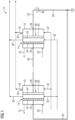
- FIG 1 shows a schematic functional block representation of an electrolysis device 12 for carbon dioxide electrolysis, in which carbon monoxide is at least partially produced from carbon dioxide during normal operation.
- the electrolysis device 12 comprises a plurality of electrochemical cells 10 in which the carbon dioxide electrolysis takes place, of which in FIG 1 two are shown as examples.
- the electrochemical cells 10 are electrically connected in series, the series connection being connected to an electrical energy source 36 by means of electrical lines 82 in order to supply the electrochemical cells 10 with electrical potentials in a corresponding manner on the respective electrodes, as will be explained below.
- Each of the electrochemical cells 10 has a cathode region 14 and an anode region 26, which are separated from one another by means of a separator 24.
- the cathode region 14 includes an electrical cathode connection 16, a gas diffusion electrode 18, which is electrically coupled to the cathode connection 16, a first supply connection 20 for supplying carbon dioxide and a first discharge connection 22 for discharging electrolytic substances at least partially formed during the intended operation of the electrochemical cell 10, which include, among other things, carbon monoxide.
- the electrolysis materials can of course also contain a residue of carbon dioxide, which has not been converted in the electrochemical cell 10. In addition, other residues are possible.
- the cathode region 14 is connected to lines 30 for supplying and discharging a catholyte, here a salt solution.
- the anode region 26 includes an electrical anode connection 28, an anode plate 50, which is electrically coupled to the electrical anode connection 28, a second supply connection 32 for supplying a proton-releasing substance, and a second discharge connection 34 for dissipating at least partially during the intended operation of the electrochemical cell 10 electrolysis residues formed.
- the cathode connection 16 and the anode connection 28 are designed to be electrically coupled to a suitable or corresponding electrical electrolysis voltage of the electrical energy source 36.
- the respective first and second supply connections 20, 32, as well as the respective first and second discharge connections 22, 34, are each connected in parallel in terms of fluid flow, so that the electrochemical cells 10 from respective sources for the corresponding substances can be supplied in normal operation.
- FIG 2 shows a schematic sectional view of one of the electrochemical cells 10 according to FIG 1 .
- the supply connections 20, 32 and the discharge connections 22, 34 are not shown.
- the cathode region 14 comprises a catholyte element 74, which adjoins a gas diffusion electrode 18, which in the present case at least partially represents the cathode.
- the gas diffusion electrode 18 also borders a contact frame 76, which in the present case is made of silver or a silver alloy.
- the contact frame 76 borders on a gas spacer element 78, which serves, among other things, to supply carbon dioxide and to remove carbon monoxide.
- the gas spacer element 78 borders on a window 18 with which the cathode region 14 is closed.
- an end plate or the like can also be provided instead of the window 18 or in addition to this.
- the structure and function of the gas diffusion electrode 18 is, for example, from the European patent application 19 182 017.4 known. Therefore, reference is made to the relevant disclosure in this regard.
- the anode plate 50 is designed to be porous in order to be able to achieve the desired gas permeability or the desired permeability for a liquid, for example water or the like.
- a contact plate 56 is arranged on the second anode surface 54.
- the contact plate 56 has a contact plate surface 68 which is connected to the second anode surface 54.
- the contact plate 56 is electrically coupled to the electrical anode connection 28.
- an end plate 72 is arranged, which closes the anode region 26 to the outside.
- the separator 24, the catalyst layer 44 and the anode plate 50 form an anode-side half cell 38 as a structural unit.
- the structural unit can also include the contact plate 56.
- the anode-side half cell 38, in particular its structure, is explained in more detail using the further following exemplary embodiments.
- Water or a salt solution can be used as anolyte, which at the same time also provides the proton-releasing substance, so that protons can be provided for the desired electrochemical reaction of carbon dioxide electrolysis.
- FIG 3 shows a first embodiment of the anode-side half cell 38 FIG 3
- the adhesive 58 is a vapor-permeable adhesive that creates a cohesive connection between the second catalyst surface 48 and the first anode surface 52.
- the adhesive can, for example, have PTFE, PVDF and N-methyl-2-pyrroloidone as a solvent. After addition, N-methyl-2-pyrroloidone dissolves the two aforementioned polymers and then, after evaporation, a solid adhesive layer forms.
- other adhesives can also be used, for example based on epoxy resin or based on cyanoacrylate.
- the adhesive 58 preferably consists of the same or similar material as the separator 24.
- the material for the separator 24 which is a perfluorinated copolymer that contains a sulfone group as an ionic group
- a similar substance should be used for the adhesive, if possible, which does not contain any foreign ones chemical components can be introduced into the electrolysis process so that the electrolysis process can remain unaffected if possible.
- the use of other adhesives is essentially limited by the fact that the electrolysis process is not significantly affected.
- the second anode surface 54 is mechanically and electrically connected to the contact plate 56 via connecting elements 70.
- the connecting elements 70 can provide a point or a continuous mechanical and electrical connection, for example by means of welding or adhesive points or by soldering or the like, depending on suitability.
- FIG 4 shows a further embodiment of an anode-side half cell 38 based on the embodiment according to FIG 3 .
- the adhesive 58 is replaced by the adhesive 60.
- the further structure corresponds to the exemplary embodiment FIG 3 .
- the adhesive 60 can basically be designed like the adhesive 58, but it also includes fibers made of iridium (IV) oxide. This allows the function to be further improved, particularly with regard to the catalytic effect. Otherwise The structure of the anode-side half cell 38 corresponds to the structure as already shown on the basis of FIG 3 has been explained.
- the adhesive 60 has a higher electrical conductivity, in particular compared to the adhesive 58.
- FIG 5 shows a further embodiment for an anode-side half cell 38 based on the embodiment according to FIG 4 , which is why additional reference is made to the relevant comments.
- iridium (IV) oxide fibers or separator strips coated with iridium (IV) oxide or possibly also other plastic or metal fibers or strips are applied to one side of the separator 24 during the production of the separator 24, namely on the anode-side separator surface 40.
- the separator 24, which thereby already contains the catalyst layer 44 is then connected to the first anode surface 52 of the anode plate 50.
- the connection can be made like this FIGS. 3 and 4 explained. In this way, the catalyst layer 44 can be connected to the separator 24 in a more mechanically stable manner.
- the adhesive 58, 60 between the catalyst layer 44 and the anode plate 50 can be arranged over the entire surface or at certain points, depending on the application.
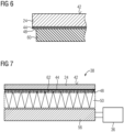
- FIG 6 shows an enlarged section of the FIG 5 in area VI.
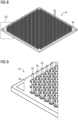
- FIGS. 8 to 10 show an embodiment based on the embodiment FIG 7 based.
- the membrane arrangement consisting of the separator 24 and the catalyst layer 44 can be pluggably connected to the anode plate 50.
- This allows not only simple assembly but also resolvability to be achieved, which allows the anode plate 50 to be separated from the membrane structure consisting of the separator 24 and the catalyst layer 44 if necessary.
- the design is as follows FIG 7 proposes that the catalyst layer 44 provides the projections 62 as pins 66. These protrude from the second catalyst surface 48 ( FIG 8).
- FIG 9 shows an enlarged section in area IX of the FIG 8 .
- FIG 10 shows the anode plate 50 in a schematic top view of the first anode surface 52. It can be seen that the catalyst layer 44 corresponds to the arrangement of the pins 66 FIG 8 Receiving openings 64 are provided. When the catalyst layer 44 is connected to the anode plate 50, the pins 66 are inserted into the receiving openings 64. As a result, a reliable mechanical and electrical connection between the anode plate 50 and the catalyst layer 44 can be achieved.
- connection is detachable. This can be achieved by an appropriate separating force, so that ultimately the anode plate 50 can be easily removed from the catalyst layer 44 again.
- an essentially powerless connection can also be provided in that the anode plate 50 comprises a locking element which allows it to be inserted in a first locking state, to enable the pins 66 to be inserted almost forcelessly into the receiving openings 64 and to fix the pins 66 in the receiving openings 64 in a second locking state. In this way, simple, detachable assembly can also be achieved.
- the structure of the electrochemical cell 10 and also the electrolysis device 12 can be significantly simplified.
- reliability can also be increased.
- potassium hydrogen carbonate or potassium sulfate or the like can be used as a catholyte.
Landscapes
- Chemical & Material Sciences (AREA)
- Organic Chemistry (AREA)
- Engineering & Computer Science (AREA)
- Chemical Kinetics & Catalysis (AREA)
- Electrochemistry (AREA)
- Materials Engineering (AREA)
- Metallurgy (AREA)
- Inorganic Chemistry (AREA)
- Electrolytic Production Of Non-Metals, Compounds, Apparatuses Therefor (AREA)
Applications Claiming Priority (2)
| Application Number | Priority Date | Filing Date | Title |
|---|---|---|---|
| DE102020204224.1A DE102020204224A1 (de) | 2020-04-01 | 2020-04-01 | Vorrichtung und Verfahren zur Kohlenstoffdioxid- oder Kohlenstoffmonoxid-Elektrolyse |
| PCT/EP2021/056136 WO2021197787A1 (de) | 2020-04-01 | 2021-03-11 | Vorrichtung und verfahren zur kohlenstoffdioxid- oder kohlenstoffmonoxid-elektrolyse |
Publications (2)
| Publication Number | Publication Date |
|---|---|
| EP4093901A1 EP4093901A1 (de) | 2022-11-30 |
| EP4093901B1 true EP4093901B1 (de) | 2023-12-27 |
Family
ID=75277965
Family Applications (1)
| Application Number | Title | Priority Date | Filing Date |
|---|---|---|---|
| EP21715146.3A Active EP4093901B1 (de) | 2020-04-01 | 2021-03-11 | Vorrichtung und verfahren zur kohlenstoffdioxid- oder kohlenstoffmonoxid-elektrolyse |
Country Status (10)
| Country | Link |
|---|---|
| US (1) | US20230145019A1 (da) |
| EP (1) | EP4093901B1 (da) |
| CN (1) | CN115398037B (da) |
| CA (1) | CA3177637C (da) |
| DE (1) | DE102020204224A1 (da) |
| DK (1) | DK4093901T3 (da) |
| ES (1) | ES2975289T3 (da) |
| FI (1) | FI4093901T3 (da) |
| PT (1) | PT4093901T (da) |
| WO (1) | WO2021197787A1 (da) |
Families Citing this family (6)
| Publication number | Priority date | Publication date | Assignee | Title |
|---|---|---|---|---|
| US11965260B2 (en) | 2022-03-22 | 2024-04-23 | Dioxycle | Augmenting syngas evolution processes using electrolysis |
| US11788022B1 (en) * | 2022-03-22 | 2023-10-17 | Dioxycle | Augmenting syngas evolution processes using electrolysis |
| US11846034B1 (en) | 2022-11-23 | 2023-12-19 | Dioxycle | Carbon monoxide electrolyzers used with reverse water gas shift reactors for the conversion of carbon dioxide into added-value products |
| US12258671B2 (en) | 2022-11-23 | 2025-03-25 | Dioxycle | Reactors and methods for production of sustainable chemicals using carbon emissions of metallurgical furnaces |
| WO2024233461A2 (en) * | 2023-05-05 | 2024-11-14 | The Johns Hopkins University | Carbon dioxide/carbon monoxide electroreduction system with gas-liquid recirculation |
| EP4570960A1 (de) * | 2023-12-14 | 2025-06-18 | Siemens Energy Global GmbH & Co. KG | Elektrolysezelle mit optimierter kontaktierung einer katalysatorschicht |
Family Cites Families (29)
| Publication number | Priority date | Publication date | Assignee | Title |
|---|---|---|---|---|
| CA971127A (en) * | 1968-07-05 | 1975-07-15 | John E. Currey | Electrolysis of dilute brine |
| US4263112A (en) * | 1980-06-20 | 1981-04-21 | Frosch Robert A | Cell and method for electrolysis of water and anode therefor |
| GB2085031B (en) * | 1980-08-18 | 1983-11-16 | Diamond Shamrock Techn | Modified lead electrode for electrowinning metals |
| CA1171817A (en) * | 1981-12-23 | 1984-07-31 | Electrolyser Corporation Ltd. (The) | Electrode structure for electrolyser cells |
| US4602984A (en) * | 1984-12-17 | 1986-07-29 | The Dow Chemical Company | Monopolar electrochemical cell having a novel electric current transmission element |
| US4923583A (en) * | 1985-11-04 | 1990-05-08 | Olin Corporation | Electrode elements for filter press membrane electrolytic cells |
| JPH07220727A (ja) * | 1994-02-07 | 1995-08-18 | Tanaka Kikinzoku Kogyo Kk | ガス拡散電極 |
| GB2348047B (en) * | 1997-03-29 | 2001-04-11 | Ballard Power Systems | Electrochemical cells |
| DE19713250C2 (de) * | 1997-03-29 | 2002-04-18 | Ballard Power Systems | Elektrochemischer Energiewandler mit Polymerelektrolytmembran |
| DE10027339A1 (de) * | 2000-06-02 | 2001-12-06 | Bayer Ag | Dimensionsstabile Gasdiffusionselektrode |
| JP4329346B2 (ja) * | 2002-02-15 | 2009-09-09 | 東亞合成株式会社 | 触媒担持電極の製造方法、並びにそれを用いた電気化学装置および燃料電池 |
| JP2006286476A (ja) * | 2005-04-01 | 2006-10-19 | Nissan Motor Co Ltd | 膜電極接合体及び膜電極接合体の製造方法 |
| JP4687695B2 (ja) * | 2007-07-23 | 2011-05-25 | トヨタ自動車株式会社 | 膜電極接合体製造方法 |
| GB2490912B (en) * | 2011-05-17 | 2015-12-23 | A Gas Internat Ltd | Electrode assembly and an electrochemical cell comprising the same |
| CN103160851B (zh) * | 2011-12-12 | 2015-11-25 | 清华大学 | 膜反应器 |
| EP2871154A4 (en) | 2012-07-06 | 2015-12-23 | Panasonic Ip Man Co Ltd | CARBON BASED MATERIAL, ELECTRODE CATALYST, ELECTRODE, GAS DIFFUSION ELECTRODE, ELECTROCHEMICAL DEVICE, FUEL BATTERY AND METHOD FOR PRODUCING CARBON BASED MATERIAL |
| JP6221067B2 (ja) * | 2013-12-03 | 2017-11-01 | パナソニックIpマネジメント株式会社 | ギ酸生成装置および方法 |
| CN104701549B (zh) * | 2013-12-06 | 2017-02-22 | 中国科学院上海高等研究院 | 一种无碳膜电极组件 |
| KR20160074241A (ko) * | 2014-12-18 | 2016-06-28 | 솔브레인 주식회사 | 전기 분해 장치 |
| CA2971603A1 (en) * | 2014-12-24 | 2016-06-30 | 3M Innovative Properties Company | Porous adhesive networks in electrochemical devices |
| WO2017094484A1 (ja) * | 2015-11-30 | 2017-06-08 | 富士フイルム株式会社 | 人工光合成モジュール |
| JP6784776B2 (ja) * | 2016-05-03 | 2020-11-11 | オーパス 12 インコーポレイテッドOpus 12 Incorporated | Co2、coおよび他の化学化合物の電気化学反応のための先進的構造を有するリアクタ |
| JP6546612B2 (ja) | 2017-02-21 | 2019-07-17 | 株式会社Subaru | 電池システムの制御装置及び電池システム |
| DE102017208610A1 (de) | 2017-05-22 | 2018-11-22 | Siemens Aktiengesellschaft | Zwei-Membran-Aufbau zur elektrochemischen Reduktion von CO2 |
| DE102017211930A1 (de) * | 2017-07-12 | 2019-01-17 | Siemens Aktiengesellschaft | Membran gekoppelte Kathode zur Reduktion von Kohlendioxid in säurebasierten Elektrolyten ohne mobile Kationen |
| JP6779849B2 (ja) * | 2017-09-19 | 2020-11-04 | 株式会社東芝 | 二酸化炭素の還元触媒体とその製造方法、還元電極、及び還元反応装置 |
| DE102017219766A1 (de) | 2017-11-07 | 2019-05-09 | Siemens Aktiengesellschaft | Anordnung für die Kohlendioxid-Elektrolyse |
| DE102018212409A1 (de) * | 2017-11-16 | 2019-05-16 | Siemens Aktiengesellschaft | Kohlenwasserstoff-selektive Elektrode |
| US20220025530A1 (en) * | 2018-09-21 | 2022-01-27 | Asahi Kasei Kabushiki Kaisha | Electrode for electrolysis and laminate |
-
2020
- 2020-04-01 DE DE102020204224.1A patent/DE102020204224A1/de not_active Withdrawn
-
2021
- 2021-03-11 EP EP21715146.3A patent/EP4093901B1/de active Active
- 2021-03-11 PT PT217151463T patent/PT4093901T/pt unknown
- 2021-03-11 CN CN202180027104.XA patent/CN115398037B/zh active Active
- 2021-03-11 FI FIEP21715146.3T patent/FI4093901T3/fi active
- 2021-03-11 DK DK21715146.3T patent/DK4093901T3/da active
- 2021-03-11 ES ES21715146T patent/ES2975289T3/es active Active
- 2021-03-11 WO PCT/EP2021/056136 patent/WO2021197787A1/de not_active Ceased
- 2021-03-11 US US17/912,511 patent/US20230145019A1/en active Pending
- 2021-03-11 CA CA3177637A patent/CA3177637C/en active Active
Also Published As
| Publication number | Publication date |
|---|---|
| DE102020204224A1 (de) | 2021-10-07 |
| CN115398037B (zh) | 2025-09-05 |
| DK4093901T3 (da) | 2024-02-05 |
| ES2975289T3 (es) | 2024-07-04 |
| EP4093901A1 (de) | 2022-11-30 |
| WO2021197787A1 (de) | 2021-10-07 |
| CA3177637C (en) | 2025-06-10 |
| PT4093901T (pt) | 2024-01-26 |
| US20230145019A1 (en) | 2023-05-11 |
| CA3177637A1 (en) | 2021-10-07 |
| CN115398037A (zh) | 2022-11-25 |
| FI4093901T3 (fi) | 2024-03-13 |
Similar Documents
| Publication | Publication Date | Title |
|---|---|---|
| EP4093901B1 (de) | Vorrichtung und verfahren zur kohlenstoffdioxid- oder kohlenstoffmonoxid-elektrolyse | |
| EP0815609B1 (de) | Zusammenfassung von einzelzellen zu einer membranelektroden-einheit und deren verwendung | |
| EP1652258B1 (de) | Membran-elektroden-einheit für die wasserelektrolyse | |
| DD211130A5 (de) | Elektrodenbauteil | |
| DE102008029628A1 (de) | Bipolarplatten-Diffusionsmedienanordnung mit niedrigem elektrischen Widerstand | |
| DE102017107422A1 (de) | Verfahren zur Herstellung einer Bipolarplatte-Stromkollektor-Einheit, Bipolarplatte-Stromkollektor-Einheit und deren Verwendung | |
| EP2417662A2 (de) | Bipolarplatte für brennstoff- oder elektrolysezellen | |
| EP1093176A2 (de) | Brennstoffzelle | |
| WO2023208279A2 (de) | Elektrochemische zelle und verfahren zur herstellung eines bauteils einer elektrochemischen zelle | |
| DE102009003074A1 (de) | Elektrochemische Zelle zur Gewinnung elektrischer Energie | |
| DE102016224696A1 (de) | Bipolarplatte für eine Brennstoffzelle und Brennstoffzelle | |
| DE102020209081A1 (de) | Elektrochemischer Reaktionszellenstapel | |
| EP1105932B1 (de) | Polymerelektrolyt-membran-brennstoffzelle | |
| WO2021198137A1 (de) | Verfahren zur herstellung einer gas- und/oder elektronenleitungsstruktur und brennstoff-/elektrolysezelle | |
| WO2018130388A1 (de) | Verfahren zur herstellung einer bipolarplatte, bipolarplatte für eine brennstoffzelle und brennstoffzelle | |
| DE112006000323T5 (de) | Brennstoffzelle | |
| EP4522786A2 (de) | Halbzellenverbund für den einsatz in elektrochemischen zellen | |
| DE102023111278A1 (de) | Elektrochemischer Zellenstapel und Verfahren zum Betrieb eines elektrochemischen Zellenstapels | |
| DE102010001760A1 (de) | Energiespeicher- und Stromerzeugungssystem | |
| WO2022084014A1 (de) | Membran-elektroden-einheit für eine elektrochemische zelle und verfahren zur herstellung einer membran-elektroden-einheit | |
| DE102020215013A1 (de) | Bipolarplatte für eine elektrochemische Zelle, Verfahren zur Herstellung der Bipolarplatte, Anordnung elektrochemischer Zellen und Verfahren zum Betrieb der Anordnung elektrochemischer Zellen | |
| DE102022205235A1 (de) | Verfahren zum Betreiben mindestens einer elektrochemischen Zelle | |
| DE102015200804B4 (de) | Membran-Elektroden-Einheit und Verfahren zur Herstellung | |
| DE102023131980A1 (de) | Membran-Elektrodeneinheit mit planarer Verstärkungskomponente | |
| DE102022213475A1 (de) | Membran-Elektroden-Einheit und Verfahren zur Herstellung einer Membran-Elektroden-Einheit |
Legal Events
| Date | Code | Title | Description |
|---|---|---|---|
| STAA | Information on the status of an ep patent application or granted ep patent |
Free format text: STATUS: UNKNOWN |
|
| STAA | Information on the status of an ep patent application or granted ep patent |
Free format text: STATUS: THE INTERNATIONAL PUBLICATION HAS BEEN MADE |
|
| PUAI | Public reference made under article 153(3) epc to a published international application that has entered the european phase |
Free format text: ORIGINAL CODE: 0009012 |
|
| STAA | Information on the status of an ep patent application or granted ep patent |
Free format text: STATUS: REQUEST FOR EXAMINATION WAS MADE |
|
| 17P | Request for examination filed |
Effective date: 20220824 |
|
| AK | Designated contracting states |
Kind code of ref document: A1 Designated state(s): AL AT BE BG CH CY CZ DE DK EE ES FI FR GB GR HR HU IE IS IT LI LT LU LV MC MK MT NL NO PL PT RO RS SE SI SK SM TR |
|
| RAP3 | Party data changed (applicant data changed or rights of an application transferred) |
Owner name: SIEMENS ENERGY GLOBAL GMBH & CO. KG |
|
| DAV | Request for validation of the european patent (deleted) | ||
| DAX | Request for extension of the european patent (deleted) | ||
| GRAP | Despatch of communication of intention to grant a patent |
Free format text: ORIGINAL CODE: EPIDOSNIGR1 |
|
| STAA | Information on the status of an ep patent application or granted ep patent |
Free format text: STATUS: GRANT OF PATENT IS INTENDED |
|
| INTG | Intention to grant announced |
Effective date: 20230811 |
|
| GRAS | Grant fee paid |
Free format text: ORIGINAL CODE: EPIDOSNIGR3 |
|
| GRAA | (expected) grant |
Free format text: ORIGINAL CODE: 0009210 |
|
| STAA | Information on the status of an ep patent application or granted ep patent |
Free format text: STATUS: THE PATENT HAS BEEN GRANTED |
|
| AK | Designated contracting states |
Kind code of ref document: B1 Designated state(s): AL AT BE BG CH CY CZ DE DK EE ES FI FR GB GR HR HU IE IS IT LI LT LU LV MC MK MT NL NO PL PT RO RS SE SI SK SM TR |
|
| REG | Reference to a national code |
Ref country code: GB Ref legal event code: FG4D Free format text: NOT ENGLISH |
|
| REG | Reference to a national code |
Ref country code: CH Ref legal event code: EP |
|
| REG | Reference to a national code |
Ref country code: DE Ref legal event code: R096 Ref document number: 502021002295 Country of ref document: DE |
|
| REG | Reference to a national code |
Ref country code: IE Ref legal event code: FG4D Free format text: LANGUAGE OF EP DOCUMENT: GERMAN |
|
| REG | Reference to a national code |
Ref country code: PT Ref legal event code: SC4A Ref document number: 4093901 Country of ref document: PT Date of ref document: 20240126 Kind code of ref document: T Free format text: AVAILABILITY OF NATIONAL TRANSLATION Effective date: 20240122 |
|
| REG | Reference to a national code |
Ref country code: DK Ref legal event code: T3 Effective date: 20240201 |
|
| REG | Reference to a national code |
Ref country code: NL Ref legal event code: FP |
|
| REG | Reference to a national code |
Ref country code: SE Ref legal event code: TRGR |
|
| REG | Reference to a national code |
Ref country code: FI Ref legal event code: FGE |
|
| PG25 | Lapsed in a contracting state [announced via postgrant information from national office to epo] |
Ref country code: GR Free format text: LAPSE BECAUSE OF FAILURE TO SUBMIT A TRANSLATION OF THE DESCRIPTION OR TO PAY THE FEE WITHIN THE PRESCRIBED TIME-LIMIT Effective date: 20240328 |
|
| REG | Reference to a national code |
Ref country code: LT Ref legal event code: MG9D |
|
| PG25 | Lapsed in a contracting state [announced via postgrant information from national office to epo] |
Ref country code: LT Free format text: LAPSE BECAUSE OF FAILURE TO SUBMIT A TRANSLATION OF THE DESCRIPTION OR TO PAY THE FEE WITHIN THE PRESCRIBED TIME-LIMIT Effective date: 20231227 |
|
| PG25 | Lapsed in a contracting state [announced via postgrant information from national office to epo] |
Ref country code: LT Free format text: LAPSE BECAUSE OF FAILURE TO SUBMIT A TRANSLATION OF THE DESCRIPTION OR TO PAY THE FEE WITHIN THE PRESCRIBED TIME-LIMIT Effective date: 20231227 Ref country code: GR Free format text: LAPSE BECAUSE OF FAILURE TO SUBMIT A TRANSLATION OF THE DESCRIPTION OR TO PAY THE FEE WITHIN THE PRESCRIBED TIME-LIMIT Effective date: 20240328 Ref country code: BG Free format text: LAPSE BECAUSE OF FAILURE TO SUBMIT A TRANSLATION OF THE DESCRIPTION OR TO PAY THE FEE WITHIN THE PRESCRIBED TIME-LIMIT Effective date: 20240327 |
|
| PG25 | Lapsed in a contracting state [announced via postgrant information from national office to epo] |
Ref country code: RS Free format text: LAPSE BECAUSE OF FAILURE TO SUBMIT A TRANSLATION OF THE DESCRIPTION OR TO PAY THE FEE WITHIN THE PRESCRIBED TIME-LIMIT Effective date: 20231227 Ref country code: LV Free format text: LAPSE BECAUSE OF FAILURE TO SUBMIT A TRANSLATION OF THE DESCRIPTION OR TO PAY THE FEE WITHIN THE PRESCRIBED TIME-LIMIT Effective date: 20231227 Ref country code: HR Free format text: LAPSE BECAUSE OF FAILURE TO SUBMIT A TRANSLATION OF THE DESCRIPTION OR TO PAY THE FEE WITHIN THE PRESCRIBED TIME-LIMIT Effective date: 20231227 |
|
| PG25 | Lapsed in a contracting state [announced via postgrant information from national office to epo] |
Ref country code: IS Free format text: LAPSE BECAUSE OF FAILURE TO SUBMIT A TRANSLATION OF THE DESCRIPTION OR TO PAY THE FEE WITHIN THE PRESCRIBED TIME-LIMIT Effective date: 20240427 |
|
| REG | Reference to a national code |
Ref country code: ES Ref legal event code: FG2A Ref document number: 2975289 Country of ref document: ES Kind code of ref document: T3 Effective date: 20240704 |
|
| PG25 | Lapsed in a contracting state [announced via postgrant information from national office to epo] |
Ref country code: CZ Free format text: LAPSE BECAUSE OF FAILURE TO SUBMIT A TRANSLATION OF THE DESCRIPTION OR TO PAY THE FEE WITHIN THE PRESCRIBED TIME-LIMIT Effective date: 20231227 |
|
| PG25 | Lapsed in a contracting state [announced via postgrant information from national office to epo] |
Ref country code: SK Free format text: LAPSE BECAUSE OF FAILURE TO SUBMIT A TRANSLATION OF THE DESCRIPTION OR TO PAY THE FEE WITHIN THE PRESCRIBED TIME-LIMIT Effective date: 20231227 |
|
| PG25 | Lapsed in a contracting state [announced via postgrant information from national office to epo] |
Ref country code: SM Free format text: LAPSE BECAUSE OF FAILURE TO SUBMIT A TRANSLATION OF THE DESCRIPTION OR TO PAY THE FEE WITHIN THE PRESCRIBED TIME-LIMIT Effective date: 20231227 Ref country code: SK Free format text: LAPSE BECAUSE OF FAILURE TO SUBMIT A TRANSLATION OF THE DESCRIPTION OR TO PAY THE FEE WITHIN THE PRESCRIBED TIME-LIMIT Effective date: 20231227 Ref country code: RO Free format text: LAPSE BECAUSE OF FAILURE TO SUBMIT A TRANSLATION OF THE DESCRIPTION OR TO PAY THE FEE WITHIN THE PRESCRIBED TIME-LIMIT Effective date: 20231227 Ref country code: IT Free format text: LAPSE BECAUSE OF FAILURE TO SUBMIT A TRANSLATION OF THE DESCRIPTION OR TO PAY THE FEE WITHIN THE PRESCRIBED TIME-LIMIT Effective date: 20231227 Ref country code: IS Free format text: LAPSE BECAUSE OF FAILURE TO SUBMIT A TRANSLATION OF THE DESCRIPTION OR TO PAY THE FEE WITHIN THE PRESCRIBED TIME-LIMIT Effective date: 20240427 Ref country code: EE Free format text: LAPSE BECAUSE OF FAILURE TO SUBMIT A TRANSLATION OF THE DESCRIPTION OR TO PAY THE FEE WITHIN THE PRESCRIBED TIME-LIMIT Effective date: 20231227 Ref country code: CZ Free format text: LAPSE BECAUSE OF FAILURE TO SUBMIT A TRANSLATION OF THE DESCRIPTION OR TO PAY THE FEE WITHIN THE PRESCRIBED TIME-LIMIT Effective date: 20231227 |
|
| PG25 | Lapsed in a contracting state [announced via postgrant information from national office to epo] |
Ref country code: PL Free format text: LAPSE BECAUSE OF FAILURE TO SUBMIT A TRANSLATION OF THE DESCRIPTION OR TO PAY THE FEE WITHIN THE PRESCRIBED TIME-LIMIT Effective date: 20231227 |
|
| PG25 | Lapsed in a contracting state [announced via postgrant information from national office to epo] |
Ref country code: PL Free format text: LAPSE BECAUSE OF FAILURE TO SUBMIT A TRANSLATION OF THE DESCRIPTION OR TO PAY THE FEE WITHIN THE PRESCRIBED TIME-LIMIT Effective date: 20231227 |
|
| REG | Reference to a national code |
Ref country code: DE Ref legal event code: R097 Ref document number: 502021002295 Country of ref document: DE |
|
| REG | Reference to a national code |
Ref country code: CH Ref legal event code: PL |
|
| PLBE | No opposition filed within time limit |
Free format text: ORIGINAL CODE: 0009261 |
|
| STAA | Information on the status of an ep patent application or granted ep patent |
Free format text: STATUS: NO OPPOSITION FILED WITHIN TIME LIMIT |
|
| PG25 | Lapsed in a contracting state [announced via postgrant information from national office to epo] |
Ref country code: LU Free format text: LAPSE BECAUSE OF NON-PAYMENT OF DUE FEES Effective date: 20240311 |
|
| PG25 | Lapsed in a contracting state [announced via postgrant information from national office to epo] |
Ref country code: MC Free format text: LAPSE BECAUSE OF FAILURE TO SUBMIT A TRANSLATION OF THE DESCRIPTION OR TO PAY THE FEE WITHIN THE PRESCRIBED TIME-LIMIT Effective date: 20231227 |
|
| PG25 | Lapsed in a contracting state [announced via postgrant information from national office to epo] |
Ref country code: MC Free format text: LAPSE BECAUSE OF FAILURE TO SUBMIT A TRANSLATION OF THE DESCRIPTION OR TO PAY THE FEE WITHIN THE PRESCRIBED TIME-LIMIT Effective date: 20231227 Ref country code: LU Free format text: LAPSE BECAUSE OF NON-PAYMENT OF DUE FEES Effective date: 20240311 |
|
| 26N | No opposition filed |
Effective date: 20240930 |
|
| PG25 | Lapsed in a contracting state [announced via postgrant information from national office to epo] |
Ref country code: IE Free format text: LAPSE BECAUSE OF NON-PAYMENT OF DUE FEES Effective date: 20240311 |
|
| PG25 | Lapsed in a contracting state [announced via postgrant information from national office to epo] |
Ref country code: IE Free format text: LAPSE BECAUSE OF NON-PAYMENT OF DUE FEES Effective date: 20240311 Ref country code: CH Free format text: LAPSE BECAUSE OF NON-PAYMENT OF DUE FEES Effective date: 20240331 |
|
| PG25 | Lapsed in a contracting state [announced via postgrant information from national office to epo] |
Ref country code: SI Free format text: LAPSE BECAUSE OF FAILURE TO SUBMIT A TRANSLATION OF THE DESCRIPTION OR TO PAY THE FEE WITHIN THE PRESCRIBED TIME-LIMIT Effective date: 20231227 |
|
| PGFP | Annual fee paid to national office [announced via postgrant information from national office to epo] |
Ref country code: AT Payment date: 20250417 Year of fee payment: 5 |
|
| PGFP | Annual fee paid to national office [announced via postgrant information from national office to epo] |
Ref country code: ES Payment date: 20250417 Year of fee payment: 5 |
|
| PG25 | Lapsed in a contracting state [announced via postgrant information from national office to epo] |
Ref country code: CY Free format text: LAPSE BECAUSE OF FAILURE TO SUBMIT A TRANSLATION OF THE DESCRIPTION OR TO PAY THE FEE WITHIN THE PRESCRIBED TIME-LIMIT; INVALID AB INITIO Effective date: 20210311 |
|
| PG25 | Lapsed in a contracting state [announced via postgrant information from national office to epo] |
Ref country code: HU Free format text: LAPSE BECAUSE OF FAILURE TO SUBMIT A TRANSLATION OF THE DESCRIPTION OR TO PAY THE FEE WITHIN THE PRESCRIBED TIME-LIMIT; INVALID AB INITIO Effective date: 20210311 |
|
| PG25 | Lapsed in a contracting state [announced via postgrant information from national office to epo] |
Ref country code: TR Free format text: LAPSE BECAUSE OF FAILURE TO SUBMIT A TRANSLATION OF THE DESCRIPTION OR TO PAY THE FEE WITHIN THE PRESCRIBED TIME-LIMIT Effective date: 20231227 |
|
| PGFP | Annual fee paid to national office [announced via postgrant information from national office to epo] |
Ref country code: SE Payment date: 20260323 Year of fee payment: 6 |
|
| PGFP | Annual fee paid to national office [announced via postgrant information from national office to epo] |
Ref country code: GB Payment date: 20260323 Year of fee payment: 6 |
|
| PGFP | Annual fee paid to national office [announced via postgrant information from national office to epo] |
Ref country code: NO Payment date: 20260318 Year of fee payment: 6 Ref country code: DK Payment date: 20260323 Year of fee payment: 6 Ref country code: DE Payment date: 20260320 Year of fee payment: 6 |
|
| PGFP | Annual fee paid to national office [announced via postgrant information from national office to epo] |
Ref country code: FI Payment date: 20260323 Year of fee payment: 6 Ref country code: BE Payment date: 20260323 Year of fee payment: 6 |
|
| PGFP | Annual fee paid to national office [announced via postgrant information from national office to epo] |
Ref country code: NL Payment date: 20260323 Year of fee payment: 6 |
|
| PGFP | Annual fee paid to national office [announced via postgrant information from national office to epo] |
Ref country code: FR Payment date: 20260323 Year of fee payment: 6 |
|
| PGFP | Annual fee paid to national office [announced via postgrant information from national office to epo] |
Ref country code: PT Payment date: 20260218 Year of fee payment: 6 |