EP4094108B1 - Éléments de distribution de télécommunications - Google Patents
Éléments de distribution de télécommunications Download PDFInfo
- Publication number
- EP4094108B1 EP4094108B1 EP21701510.6A EP21701510A EP4094108B1 EP 4094108 B1 EP4094108 B1 EP 4094108B1 EP 21701510 A EP21701510 A EP 21701510A EP 4094108 B1 EP4094108 B1 EP 4094108B1
- Authority
- EP
- European Patent Office
- Prior art keywords
- tray
- cover
- cable
- movable
- hinge
- Prior art date
- Legal status (The legal status is an assumption and is not a legal conclusion. Google has not performed a legal analysis and makes no representation as to the accuracy of the status listed.)
- Active
Links
Images


Classifications
-
- G—PHYSICS
- G02—OPTICS
- G02B—OPTICAL ELEMENTS, SYSTEMS OR APPARATUS
- G02B6/00—Light guides; Structural details of arrangements comprising light guides and other optical elements, e.g. couplings
- G02B6/44—Mechanical structures for providing tensile strength and external protection for fibres, e.g. optical transmission cables
- G02B6/4439—Auxiliary devices
- G02B6/444—Systems or boxes with surplus lengths
- G02B6/4453—Cassettes
- G02B6/4455—Cassettes characterised by the way of extraction or insertion of the cassette in the distribution frame, e.g. pivoting, sliding, rotating or gliding
-
- G—PHYSICS
- G02—OPTICS
- G02B—OPTICAL ELEMENTS, SYSTEMS OR APPARATUS
- G02B6/00—Light guides; Structural details of arrangements comprising light guides and other optical elements, e.g. couplings
- G02B6/44—Mechanical structures for providing tensile strength and external protection for fibres, e.g. optical transmission cables
- G02B6/4439—Auxiliary devices
- G02B6/444—Systems or boxes with surplus lengths
- G02B6/4452—Distribution frames
- G02B6/44526—Panels or rackmounts covering a whole width of the frame or rack
Definitions
- the present invention relates to telecommunications distribution systems, e.g., optical fiber distribution systems, which may include a rack and elements which populate the rack, wherein such fiber optic elements can include fiber terminations, patching, fiber splitters, and fiber splices.
- telecommunications distribution systems e.g., optical fiber distribution systems
- such fiber optic elements can include fiber terminations, patching, fiber splitters, and fiber splices.
- Optical fiber distribution systems may include fiber terminations and other equipment which is typically rack mounted.
- Various concerns exist for the optical fiber distribution systems including density, ease of use and mounting, and cable management.
- US 2008/050083 A1 , US 2019/025521 A1 and WO 2019/201878 A1 disclose prior art optical distribution systems.
- One implementation of a system in accordance with the examples of the disclosure includes a building block element mountable to a rack or other structure.
- the element includes a chassis and a movable tray.
- the tray is movably mounted to the chassis with a slide mechanism that allows the tray to slide relative to the chassis, wherein the tray may house equipment for fiber terminations, patching, splitting, and splicing.
- the elements can be stacked in a column with each tray slideable in a horizontal direction. In the case of a column of elements, a selected tray is pulled outward to access the desired tray.
- each element can be for patch cables, and the opposite side can be for cable termination of an incoming cable, such as a distribution cable or a feeder cable.
- the elements can be configured as desired and form building blocks for an optical fiber distribution system. When the elements are mounted in a column in a rack, the cables can be placed in vertical cable guides to enter and exit the selected element.
- An example rack may be front accessible. However, the elements shown and described can be used in other racks, frames, cabinets, or boxes including in arrangements where rear access is desirable or useful.
- the disclosure is directed to an optical fiber distribution element that includes a chassis defining an interior; a movable tray slidably movable from within the chassis to a position at least partially outside the chassis, the tray defining a front end and a rear end; a slide mechanism which connects the movable tray to the chassis; at least one hingedly mounted frame member within the tray which hinges about an axis perpendicular to the direction of movement of the movable tray; and a cover mounted adjacent the rear end of the tray and movable between an access position and an operational position when the tray is in the open position, only the operational position of the cover allowing the tray to move from the open position to the closed position, the access position allowing access to the at least one hingedly mounted frame member, and the cover in the access position preventing the tray from moving from the open to the closed position.
- an optical fiber distribution element 10 can be individually mounted as desired to telecommunications equipment including racks, frames, or cabinets.
- the element 10 can be mounted in groups or blocks which can form a stacked arrangement.
- a vertical stack of elements 10 can populate an optical fiber distribution rack.
- Each element 10 can hold fiber terminations or other fiber components including fiber splitters and/or fiber splices.
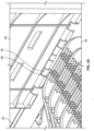
- the example depicted optical fiber distribution element 10 that is going to be referenced for describing the inventive features of the disclosure is a drawer-based dedicated splice element that includes, within its tray, cable management structures for guiding cabling to and from hinged splice frames (also referred to herein as splice trays).
- the element 10 includes a chassis 20 and a movable tray 24.
- Tray 24 is movable with a slide mechanism 30.
- Slide mechanism 30 provides for synchronized movement for managing the cables extending to and from tray 24. Entry points 36 on either side of chassis 20 allow for fixation of the input and output cables associated with each element 10.
- U-shaped radius limiters 38 associated with each slide mechanism 30 move in synchronized movement relative to chassis 20 and tray 24 to maintain fiber slack, without causing fibers to be bent, pinched, or pulled.
- the depicted optical fiber distribution element 10 that is going to be referenced for describing the inventive features of the disclosure is a dedicated splice element that includes, within its tray, cable management structures for guiding cabling to and from the hinged splice frames.
- incoming outside plant (OSP) cabling 50 may be directed to pivotally mounted splice frames 52 (may also be referred to as splice trays or pivot trays).
- OSP outside plant
- splice frames 52 may also be referred to as splice trays or pivot trays.
- each fiber of the OSP cable 50 may be spliced to a pigtail 54 (i.e., outgoing cabling) that may lead to another element or other points in the network such as other equipment or customer dwellings.
- the incoming cabling 50 may follow a path from an exterior of the element 10, through U-shaped movable radius limiters 38, to the interior pivot trays 52.
- the outgoing cabling 54 may follow a similar path, where the cabling 54 is routed through U-shaped radius limiters 38 at the opposite side of the elements 10.
- the incoming cabling 50 may be provided with strength members that are secured to the sides of the elements via cable fixation devices 60 such as those described in PCT Publication No. WO 2019/201878 .
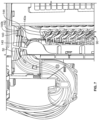
- FIGS. 2-11 certain inventive interior features of the trays 24 of elements such as the element 10 shown in FIG. 1 will be described.
- FIGS. 2-3 illustrate the details of a cover portion 62 of the tray 24 that is configured to protect the pivotally mounted splice frames 52 provided along a center portion of the tray 24.
- the cover 62 is hinged adjacent a back end 64 of the tray 24 and is openable in a front-to-back direction, where the cover 62 is pivotally liftable from a front end 66 of the cover 62.
- a flexible latch 68 provided at the front 66 of the cover 62 is used to keep the cover 62 closed by being snap-fit into a latch opening 70 provided at a front end 72 of the tray 24.
- a latch grip 74 can be elastically moved by a user in a front-to-back direction to free a latch lip 76 from the latch opening 70 before pivotally lifting the cover 62.
- the arrangement of the cover 62 where the hinge is positioned at the back end 64 of the tray 24 provides a safety feature for protecting the splice trays 52 and the fibers therein within the tray 24.
- Each of the splice frames or trays 52 first must be pivoted down before the cover 62 itself can be brought down and snapped to a closed position.
- slideable closure of the tray 24 is prevented by contact of the cover 62 with the chassis 20 of the distribution element 10.
- closure of the cover 62 requires closure of each of the splice trays 52, accidental closure of the tray 24 and pinching or damaging any of the fibers within the splice trays 52 is prevented or at least limited.
- cover 62 is configured to prevent movement of tray 24 to the closed position when cover 62 is not in the closed position itself as noted above.
- the closed position of the cover 62 may also be referred to as the operational position, and the open position of the cover 62 may be referred to as the access position where the splice trays 52 may be accessed.
- a hinge 78 of the cover 62 and a hinge receiver 80 of the tray 24 may be configured such that the cover 62 remains or is locked in an open position when pivoted open.
- the hinge 78 of the cover 62 may utilize a square or other polygonal shaped cross-section where sharp edges of the cross-section provide temporary stops within the hinge receiver 80 to enable the cover 62 to remain open when brought to an open position.
- the hinge 78 of the cover 62 and the hinge receiver 80 of the tray 24 provide a self-supporting locking system to keep the cover 62 in an open position without the need for further structures or features.
- the cover 62 may be used to house a card 82 (i.e., identification card) that can be used to write or provide connectivity information thereon regarding the distribution element 10.
- the card 82 is removably mounted to a card slot 84 provided on the cover 62 via tabs 86 provided around the perimeter of the card slot 84. Even though the card 82 is removable from the cover 62, the cover 62 provides access to the card 82 such that distribution information can be written on the card 82 without removal from the cover 62.
- FIG. 4 shows the tray 24 of FIGS. 2-3 without the cover 62 or the hinged splice frames 52 to illustrate the details of inventive cable management structures 90 within the tray 24.
- a cable management structure 90 is provided at each of the right and left sides 92, 94 of tray 24.
- the cable management structures 90 are for guiding cabling to and from the hinged splice trays 52.
- the cable management structure 90 may be provided as a removable insert. As such, if the cable management insert 90 is damaged in any way, the insert may be replaced with another. In other embodiments, the cable management structure may be integrally molded with the tray of the distribution element 10.
- each cable management insert 90 extends in a front-to-back direction, on opposing sides of the flip trays 52.
- a series of curved radius limiters 96 are provided for guiding cabling to and from the splice trays 52.
- each cable management insert 90 defines a double layered cable routing channel defined by a lower channel 98 and an upper channel 100, wherein cable management fingers 102 separate the lower channel 98 from the upper channel 100.
- the lower channel 98 may be used for 250 micron or 900 micron optical fibers 50 and the upper channel 100 may be used for the pigtails 54.
- the dual layered construction provides a physical separation between two different types of cabling and may provide extra protection to the smaller 250 micron or 900 micron optical fibers 50 in the lower channel 98.
- the upper channel 100 is also provided with cable retention fingers 104 extending into and partially covering the upper channel 100 for retaining the pigtails 54 within the upper channel 100.
- FIGS. 5 and 6 details on the locking feature for pivotally mounting the splice frames 52 to the tray 24 are illustrated.
- FIG. 5 illustrates a prior art version of a locking feature 110 provided between a tray such as the tray 24 shown in FIGS. 2-4 and a hinged splice frame 52 therein for pivotally mounting the splice frame 52 within such a tray 24.
- each frame mounting location 112 within the tray 24 defines hinge openings 114 and a flexible ramped tab 116 positioned between the hinge openings 114.
- Hinge pins 118 defined on each splice tray 52 are configured to be horizontally slidably inserted into the hinge openings 114 while a retention tab 120 defined on the splice tray 52 slides over and pushes down on the flexible ramped tab 116. Once the flexible ramped tab 116 is cleared, the retention tab 120 is locked in against a stop surface 122 defined by the ramped tab 116. In this manner, the splice trays 52 are limited from removal unless the ramped tab 116 is flexed down and the hinge pins 118 are slid.
- FIG. 6 illustrates an improved version of a locking feature 130 according to the claimed invention provided between the tray 24 of FIGS. 2-4 and the hinged splice frames 52.
- a flexible ramped tab 132 is provided with flexibility along a horizontal plane defined by a bottom surface/wall 134 of the tray 24, which is in a perpendicular direction relative to the flex direction shown for the version of the tab 116 in FIG. 5 .
- the flexible ramped tab 132 is provided within an aperture 136 defined by the bottom wall 134 of the tray 24.
- Edges 138 defining the aperture 136 provide positive stops for the flexible ramped tab 132 so as to limit over-flexing of the ramped tab 132. In this manner, the flexible ramped tab 132 has a limit in its travel and is not as susceptible to breaking off.
- the flexible ramped tab 116 is not limited in its travel since the ramped tab 116 is not provided with any positive stops.
- repetitive flexing of the ramped tab 116 in FIG. 5 might result in faster deformation or failure of the tab 116 versus the ramped tab 132 shown in FIG. 6 which is provided with a positive stop.
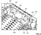
- FIG. 7 details relating to example tube holders 140 that are configured to be mounted within the tray 24 of FIGS. 2-4 that can frictionally support fiber carrying tubes 50 is discussed.
- the tube holders 140 may be mounted so as to align with the channels of the movable U-shaped radius limiters 38 of the distribution elements 10.
- the tube holders 140 may be configured for tubes holding 250 micron fibers or for tubes holding 900 micron fibers, depending on the application.
- the tube holders 140 include friction members 142 which limit the amount of sliding movement of cables 50 passing through the tube holders 140, to assist with cable management. Friction members 142 grip lightly on the cables 50 in the tube holders 140 to reduce or eliminate sliding movement of the cables 50 therein.
- Such tube holders 140 may also be positioned at various locations within the trays 24 for guiding of cabling in the preferred paths. As shown in an example layout in FIG. 7 , one of the tube holders 140a is positioned to lead fiber carrying tubes 50 toward the cable management insert 90.
- a second tuber holder 140b may be positioned and may also cooperate with a channel 144 defined at the back 64 of the tray 24 to lead fiber carrying tubes to an opposite side of the tray 24 to provide for a side-switching concept.
- the second tube holder 140b that is shown to be provided at the rear 64 of the tray 24 can be mounted at either the right side 92 or the left side 94 of the tray 24 and may bypass the splice frames 52 on one side and lead fiber carrying tubes to the opposite side depending upon the connectivity need.
- FIG. 8 illustrates another version of a tray 24b similar to the tray 24 of FIGS. 2-4 that includes a further cable management wall 150 on both sides of the tray 24b for guiding cabling within the tray 24b.
- the cable management walls 150 can cooperate with the cable channel 144 at the back 64 of the tray 24b and guide fiber holding tubes extending from an opposite side of the tray 24b toward the radius limiters 96 defined by the cable management insert 90 when a side-switching operation is performed.
- Each cable management wall 150 is provided with a cable retention finger 152 for retaining the cables.
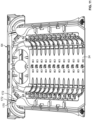
- FIGS. 9-10 illustrate a retainer 160 configured to be mounted within a tray such as the tray 24 of FIGS. 2-4 .
- the retainer 160 is configured to hold a plurality of cable termination units 162 in a stacked arrangement.
- the example retainer 160 has the same mounting interface as the above-discussed tube holders 140 and can be mounted at various locations within the tray 24.
- each retainer 160 is shown to hold four cable termination units 162 in a stacked arrangement. Other numbers are certainly possible depending upon connectivity need.
- the cable termination units 162 allow termination of cables inside the trays 24.
- a cable channel 164 is defined for receiving the cable. Strength members may be tied down or clamped within each cable termination unit 162 for securing the cables.
- FIG. 11 illustrates an example of another cable retention feature 170.
- the cable retention feature 170 is shown to be used at both sides of the tray 24 adjacent to the back end 64 for transitioning cabling 50 ( FIG. 1 ) from the U-shaped cable radius managers 38 to the main body of the tray 24.
- the cable retention feature 170 is formed from two flexible fingers 172 that provide a push-through design.
- the flexible fingers 172 allow cabling 50 surrounded by corrugated tubes 51 (i.e., flex tubes) or pigtails to be pushed through and retained thereunder.
Landscapes
- Physics & Mathematics (AREA)
- General Physics & Mathematics (AREA)
- Optics & Photonics (AREA)
- Light Guides In General And Applications Therefor (AREA)
Claims (12)
- Élément de distribution de fibres optiques (10) comprenant :un châssis (20) définissant un intérieur ;un plateau mobile (24) mobile de manière coulissante à partir de l'intérieur du châssis (20) jusqu'à une position au moins partiellement à l'extérieur du châssis (20), le plateau (24) définissant une extrémité avant (72) et une extrémité arrière (64) ;un mécanisme coulissant (30) qui relie le plateau mobile (24) au châssis (20) ;l'au moins un élément de cadre monté de manière articulée (52) au sein du plateau (24) qui s'articule autour d'un axe perpendiculaire à la direction de déplacement du plateau mobile (24) ; etun couvercle (62) monté adjacent à l'extrémité arrière (64) du plateau (24) et mobile entre une position d'accès et une position fonctionnelle lorsque le plateau (24) est dans une position ouverte, seule la position fonctionnelle du couvercle (62) permettant au plateau (24) de se déplacer de la position ouverte à une position fermée, la position d'accès permettant l'accès à l'au moins un élément de cadre monté de manière articulée (52), et le couvercle (62) dans la position d'accès empêchant le plateau (24) de se déplacer de la position ouverte à la position fermée ;caractérisé en ce quel'au moins un élément de cadre monté de manière articulée (52) est monté de manière amovible sur le plateau (24) par l'intermédiaire d'une structure de verrouillage (130),dans lequel la structure de verrouillage (130) est définie par une broche d'articulation (118) et une patte de retenue (120) espacée définie sur l'élément de cadre (52) et une ouverture d'articulation (114) et une patte flexible (132) définie sur le plateau (24), l'ouverture d'articulation (114) étant configurée pour recevoir la broche d'articulation (118) dans une direction d'insertion et la patte flexible (132) étant configurée pour fléchir élastiquement le long d'un plan horizontal défini par une paroi de fond (134) du plateau (24) pour recevoir la patte de retenue (120) et pour fournir une surface d'arrêt pour empêcher un mouvement coulissant de la patte de retenue (120) dans une direction qui est opposée à la direction d'insertion de la broche d'articulation (118) dans l'ouverture d'articulation (114), etdans lequel la patte flexible (132) est prévue au sein d'un orifice (136) défini par le plateau (24), dans lequel au moins un bord (138) du plateau (24) qui définit l'orifice (136) est configuré pour fournir une butée positive pour limiter le mouvement flexible de la patte flexible (132) le long du plan horizontal défini par la paroi de fond (134) du plateau (24).
- Élément (10) selon la revendication 1, dans lequel le plateau (24) comprend une pluralité d'éléments de cadre (52) montés de manière articulée pour un mouvement indépendant, chacun des éléments de cadre (52) pouvant être recouvert par le couvercle (62).
- Élément (10) selon la revendication 2, dans lequel la pluralité d'éléments de cadre (52) sont empilés le long d'une ligne qui est généralement parallèle à la direction de déplacement du plateau mobile (24).
- Élément (10) selon la revendication 1, dans lequel le mécanisme coulissant (30) comprend un limiteur de rayon (38) qui se déplace avec un mouvement synchronisé par rapport au châssis (20) et au plateau (24) pendant le mouvement coulissant du plateau (24).
- Élément (10) selon la revendication 1, dans lequel un câble entrant ou sortant du plateau mobile (24) suit un chemin en forme de S lorsque le câble s'étend entre un extérieur du plateau mobile (24) et l'au moins un élément de cadre monté de manière articulée (52).
- Élément (10) selon la revendication 1, dans lequel l'au moins un élément de cadre monté de manière articulée (52) est configuré pour supporter une épissure de fibres optiques.
- Élément (10) selon la revendication 1, dans lequel le couvercle (62) comprend une carte amovible (82) pour recevoir des indices concernant des informations de connectivité de fibre optique au sein du plateau mobile (24).
- Élément (10) selon la revendication 1, dans lequel le couvercle (62) comprend une articulation (78) qui est reçue par un récepteur d'articulation (80) défini sur le plateau mobile (24), l'articulation (78) du couvercle (62) et le récepteur d'articulation (80) du plateau (24) étant configurés de manière coopérative pour conserver automatiquement le couvercle (62) dans la position d'accès lorsque le couvercle (62) a été amené dans la position d'accès.
- Élément (10) selon la revendication 1, comprenant en outre une structure de gestion de câbles (90) au sein du plateau (24) pour gérer des câbles s'étendant entre le mécanisme coulissant (30) et l'au moins un élément de cadre monté de manière articulée (52) au sein du plateau (24), la structure de gestion de câbles (90) définissant une structure à deux couches définissant un canal inférieur (98) séparé d'un canal supérieur (100) par des doigts de gestion de câbles (102).
- Élément (10) selon la revendication 9, dans lequel la structure de gestion de câbles (90) est prévue comme un insert amovible.
- Élément (10) selon la revendication 9, dans lequel le plateau (24) comprend deux des structures de gestion de câbles (90), chacune étant située sur un côté opposé de l'au moins un élément de cadre monté de manière articulée (52).
- Élément (10) selon la revendication 11, dans lequel le plateau (24) comprend à l'intérieur un type de câble (54) au sein du canal supérieur (100) d'au moins une des structures de gestion de câbles (90) différent du type de câble (50) au sein du canal inférieur (98) de l'au moins une des structures de gestion de câbles (90).
Applications Claiming Priority (2)
| Application Number | Priority Date | Filing Date | Title |
|---|---|---|---|
| US202062965241P | 2020-01-24 | 2020-01-24 | |
| PCT/EP2021/051368 WO2021148552A1 (fr) | 2020-01-24 | 2021-01-21 | Éléments de distribution de télécommunications |
Publications (2)
| Publication Number | Publication Date |
|---|---|
| EP4094108A1 EP4094108A1 (fr) | 2022-11-30 |
| EP4094108B1 true EP4094108B1 (fr) | 2025-06-18 |
Family
ID=74215953
Family Applications (1)
| Application Number | Title | Priority Date | Filing Date |
|---|---|---|---|
| EP21701510.6A Active EP4094108B1 (fr) | 2020-01-24 | 2021-01-21 | Éléments de distribution de télécommunications |
Country Status (3)
| Country | Link |
|---|---|
| US (2) | US12099246B2 (fr) |
| EP (1) | EP4094108B1 (fr) |
| WO (1) | WO2021148552A1 (fr) |
Families Citing this family (2)
| Publication number | Priority date | Publication date | Assignee | Title |
|---|---|---|---|---|
| EP3781973A1 (fr) * | 2018-04-17 | 2021-02-24 | CommScope Connectivity Belgium BVBA | Éléments de distribution de télécommunications |
| WO2020214817A1 (fr) * | 2019-04-17 | 2020-10-22 | Commscope Technologies Llc | Guide-câble de télécommunications |
Family Cites Families (291)
| Publication number | Priority date | Publication date | Assignee | Title |
|---|---|---|---|---|
| US2864656A (en) | 1954-06-25 | 1958-12-16 | Yorinks Alexander | Slide mechanism |
| NL193890A (fr) | 1954-12-27 | |||
| US3901564A (en) | 1973-10-29 | 1975-08-26 | Henry P Armstrong | Drawer extensible slide chassis |
| US4070076A (en) | 1977-05-05 | 1978-01-24 | The Raymond Lee Organization, Inc. | Drawer sliding device |
| DE2735106C2 (de) | 1977-08-04 | 1983-09-01 | AEG-Telefunken Nachrichtentechnik GmbH, 7150 Backnang | Kabelgarnitur für ein Fernmeldekabel |
| US4172625A (en) | 1977-12-15 | 1979-10-30 | Comerco, Inc. | Drawer extenders |
| DE2918572A1 (de) | 1978-06-13 | 1980-01-03 | Blum Gmbh Julius | Ausziehfuehrungsgarnitur fuer schubladen |
| DE2918309C2 (de) | 1979-05-07 | 1982-11-04 | Heino Schulz Kunststoffverarbeitung, 5300 Bonn | Schubkasten-Auszugvorrichtung |
| US4359262A (en) | 1980-06-30 | 1982-11-16 | Northern Telecom Limited | Tray for organizing optical fiber splices and enclosures embodying such trays |
| US4373776A (en) | 1980-06-30 | 1983-02-15 | Northern Telecom Limited | Protection case for optical fiber splices |
| JPS58109707U (ja) | 1982-01-19 | 1983-07-26 | 日本電気株式会社 | 端子盤収納装置 |
| FR2531576A1 (fr) | 1982-08-04 | 1984-02-10 | Cit Alcatel | Bati de raccordement et d'interface opto-electronique |
| FR2531544B1 (fr) | 1982-08-04 | 1985-01-25 | Cit Alcatel | Tete de cable optique |
| JPS5974523A (ja) | 1982-10-21 | 1984-04-27 | Furukawa Electric Co Ltd:The | 光フアイバ接続箱 |
| FR2538918A1 (fr) | 1983-01-05 | 1984-07-06 | Telecommunications Sa | Boite de raccordement et de brassage pour fibres optiques |
| DE3308682C2 (de) | 1983-03-11 | 1985-12-05 | Krone Gmbh, 1000 Berlin | Matrix-Hauptverteiler |
| US4494806A (en) | 1983-05-13 | 1985-01-22 | Leslie Metal Arts Company | Spring loaded drawer assembly with mechanical damping |
| US4595255A (en) | 1983-08-24 | 1986-06-17 | Fiberlan, Inc. | Optical fiber wiring center |
| FR2556895B1 (fr) | 1983-12-20 | 1986-12-19 | Lignes Telegraph Telephon | Dispositif de raccordement de cables, notamment a fibres optiques |
| DE3347621A1 (de) | 1983-12-30 | 1985-07-11 | Wilhelm Sedlbauer GmbH Fabrik für Feinmechanik und Elektronik, 8000 München | Verteilergestell fuer glasfaser-kabelenden |
| JPS60169811A (ja) | 1984-02-14 | 1985-09-03 | Furukawa Electric Co Ltd:The | 光フアイバ接続余長収納装置 |
| GB2138057B (en) | 1984-04-11 | 1987-09-30 | Tekken Constr Co | Method of building strengthened, embanked foundation |
| US4630886A (en) | 1984-04-16 | 1986-12-23 | At&T Bell Laboratories | Lightguide distributing unit |
| JPS6155607A (ja) | 1984-08-28 | 1986-03-20 | Fujitsu Ltd | 光分配盤 |
| JPS6190104A (ja) | 1984-10-09 | 1986-05-08 | Nec Corp | 光アダプタの設置構造 |
| CA1249741A (fr) | 1984-10-25 | 1989-02-07 | Michael J. Donaldson | Materiel de raccordement de cable a fibres optiques |
| FR2575020B1 (fr) | 1984-12-14 | 1987-02-13 | Nozick Jacques | Repartiteur pour cables optiques |
| US4699455A (en) | 1985-02-19 | 1987-10-13 | Allen-Bradley Company | Fiber optic connector |
| DE3511653A1 (de) | 1985-03-29 | 1986-10-02 | Siemens AG, 1000 Berlin und 8000 München | Gestell mit einsatz fuer ein kupplungsfeld zwischen glasfaserkabeln |
| US4765710A (en) | 1985-07-30 | 1988-08-23 | Siemens Aktiengesellschaft | Distributing frame for optical waveguides and the like |
| FR2587127B1 (fr) | 1985-09-06 | 1987-10-23 | Valleix Paul | Structure pour connexions optiques |
| US4792203A (en) | 1985-09-17 | 1988-12-20 | Adc Telecommunications, Inc. | Optical fiber distribution apparatus |
| US4737039A (en) | 1986-12-08 | 1988-04-12 | Knape & Vogt Manufacturing Company | Drawer rail carrier roller mount |
| US4840449A (en) | 1988-01-27 | 1989-06-20 | American Telephone And Telegraph Company, At&T Bell Laboratories | Optical fiber splice organizer |
| US4820007A (en) | 1988-02-12 | 1989-04-11 | American Telephone And Telegraph Company At&T Bell Laboratories | Cable closure and methods of assembling |
| US4898448A (en) | 1988-05-02 | 1990-02-06 | Gte Products Corporation | Fiber distribution panel |
| US4900123A (en) | 1988-08-29 | 1990-02-13 | Gte Products Corporation | 1550 nm fiber distribution panel |
| DE3836273C2 (de) | 1988-10-25 | 1997-05-07 | Standard Praezision Gmbh | Synchronisierte dreigliedrige Teleskopschiene für Zugglieder |
| DE3838428A1 (de) | 1988-11-12 | 1990-05-31 | Philips Patentverwaltung | Schaltverteiler zur herstellung von frei waehlbaren optischen steckverbindungen |
| US5071211A (en) | 1988-12-20 | 1991-12-10 | Northern Telecom Limited | Connector holders and distribution frame and connector holder assemblies for optical cable |
| US5013121A (en) | 1989-06-29 | 1991-05-07 | Anton Mark A | Optical fiber storage container |
| US5067678A (en) | 1989-07-31 | 1991-11-26 | Adc Telecommunications, Inc. | Optic cable management system |
| US5316243A (en) | 1989-07-31 | 1994-05-31 | Adc Telecommunications, Inc. | Optic cable management |
| US4995688A (en) | 1989-07-31 | 1991-02-26 | Adc Telecommunications, Inc. | Optical fiber distribution frame |
| US4986762A (en) | 1989-08-15 | 1991-01-22 | Minnesota Mining And Manufacturing Company | Termination module for use in an array of modules |
| US4971421A (en) | 1989-09-29 | 1990-11-20 | Reliance Comm/Tec Corporation | Fiber optic splice and patch enclosure |
| US5142606A (en) | 1990-01-22 | 1992-08-25 | Porta Systems Corp. | Optical fiber cable distribution frame and support |
| US5100221A (en) | 1990-01-22 | 1992-03-31 | Porta Systems Corp. | Optical fiber cable distribution frame and support |
| US4991928A (en) | 1990-02-20 | 1991-02-12 | Siecor Corporation | Movable clamp for fiber optic enclosures |
| US5142607A (en) | 1990-03-20 | 1992-08-25 | Rittal-Werk Rudolf Loh Gmbh & Co. Kg | Splice box for optical wave guide |
| US5174675A (en) | 1990-05-07 | 1992-12-29 | Inventio Ag | Guide bar for an elevator door |
| FR2663917B1 (fr) | 1990-06-29 | 1993-06-04 | Cit Alcatel | Dispositif modulaire pour le stockage de reserves de support de transmission sur des liaisons, notamment a fibre optique. |
| US5066149A (en) | 1990-09-11 | 1991-11-19 | Adc Telecommunications, Inc. | Splice tray with slack take-up |
| EP0479226B1 (fr) | 1990-10-04 | 1997-03-05 | Alcatel Cable Interface | Cassette de raccordement optique |
| US5138688A (en) | 1990-11-09 | 1992-08-11 | Northern Telecom Limited | Optical connector holder assembly |
| US5127082A (en) | 1991-03-22 | 1992-06-30 | The Siemon Company | Fiber optic patch panel |
| US5129030A (en) | 1991-05-30 | 1992-07-07 | At&T Bell Laboratories | Movable lightguide connector panel |
| FR2678076B1 (fr) | 1991-06-20 | 1994-09-23 | Cit Alcatel | Module de stockage d'une reserve de support de transmission sur une liaison, notamment a fibre optique et dispositif de stockage comportant un ensemble de tels modules. |
| US5167001A (en) | 1991-09-03 | 1992-11-24 | Northern Telecom Limited | Optical fiber storage and connector tray and shelf and tray assembly |
| DE4133375C1 (fr) | 1991-10-05 | 1993-04-22 | Krone Ag | |
| FR2682488B1 (fr) | 1991-10-15 | 1994-01-21 | Bruno Capelle | Tete de cables modulaire a fibres optiques de grande capacite . |
| ES1019586Y (es) | 1991-12-12 | 1992-11-01 | Telefonica De Espana, S.A. | Conjunto terminal de empalme y reparticion optica modular. |
| US5247603A (en) | 1992-01-24 | 1993-09-21 | Minnesota Mining And Manufacturing Company | Fiber optic connection system with exchangeable cross-connect and interconnect cards |
| FR2687744B1 (fr) | 1992-02-21 | 1994-04-08 | Mars Actel | Ensemble de modules plats articules. |
| FR2687800B1 (fr) | 1992-02-21 | 1994-04-08 | Mars Actel | Cassette adaptable de lovage et d'epissurage de fibres optiques. |
| US5202942A (en) | 1992-04-03 | 1993-04-13 | Amp Incorporated | Cable termination member for fiber optic connectors having improved strain relief |
| US5275064A (en) | 1992-06-12 | 1994-01-04 | General Devices Co., Inc. | Extensible platform with cable drive system |
| US5240209A (en) | 1992-11-17 | 1993-08-31 | Telect, Inc. | Telecommunication multiple cable carrier |
| US5323480A (en) | 1992-11-25 | 1994-06-21 | Raychem Corporation | Fiber optic splice closure |
| US5335349A (en) | 1992-12-14 | 1994-08-02 | Telect, Inc. | Telecommunication overhead cable distribution assembly |
| FR2703160B1 (fr) | 1993-03-26 | 1995-06-02 | Corning Inc | Cassette pour dispositif à fibres optiques, équipée d'un faisceau de tubes souples de protection des fibres. |
| US5363467A (en) | 1993-05-28 | 1994-11-08 | Minnesota Mining And Manufacturing Company | Compact fiber optic housing |
| US5339379A (en) | 1993-06-18 | 1994-08-16 | Telect, Inc. | Telecommunication fiber optic cable distribution apparatus |
| US5412751A (en) | 1993-08-31 | 1995-05-02 | The Siemon Company | Retrofittable multimedia patch management system |
| GB9318632D0 (en) | 1993-09-08 | 1993-10-27 | Raychem Sa Nv | Optical fibre organizer |
| GB9318633D0 (en) | 1993-09-08 | 1993-10-27 | Raychem Sa Nv | Organization of optical fibres |
| US5353367A (en) | 1993-11-29 | 1994-10-04 | Northern Telecom Limited | Distribution frame and optical connector holder combination |
| US5490229A (en) | 1993-12-08 | 1996-02-06 | At&T Ipm Corp. | Slidably mounted optical fiber distribution tray |
| TW232757B (en) | 1994-01-21 | 1994-10-21 | Adc Telecommunications Inc | High-density fiber distribution frame |
| US5402515A (en) | 1994-03-01 | 1995-03-28 | Minnesota Mining And Manufacturing Company | Fiber distribution frame system, cabinets, trays and fiber optic connector couplings |
| DE4413136C1 (de) | 1994-04-19 | 1995-05-04 | Loh Kg Rittal Werk | LWL(Lichtwellenleiter)-Spleißbox |
| US5511144A (en) | 1994-06-13 | 1996-04-23 | Siecor Corporation | Optical distribution frame |
| GB2292466B (en) | 1994-08-15 | 1997-09-10 | Pirelli General Plc | Guiding optical fibres in ducts |
| US5530783A (en) | 1994-08-31 | 1996-06-25 | Berg Technology, Inc. | Backplane optical fiber connector for engaging boards of different thicknesses and method of use |
| WO1996010203A1 (fr) | 1994-09-28 | 1996-04-04 | Telephone Cables Limited | Plateau a epissures |
| US5509096A (en) | 1994-10-28 | 1996-04-16 | Syntec Inc. | Receptacle and plug fiber optic connector assembly |
| DE4442823A1 (de) | 1994-12-01 | 1996-06-05 | Siemens Ag | Kassettenmodul für Lichtwellenleiter |
| DE29504191U1 (de) | 1995-03-01 | 1996-03-28 | Krone Ag, 14167 Berlin | Einschub für Aufnahmeeinrichtungen der LWL-Technik |
| US5613030A (en) | 1995-05-15 | 1997-03-18 | The Whitaker Corporation | High density fiber optic interconnection enclosure |
| US5724469A (en) | 1996-01-26 | 1998-03-03 | Ortronics, Inc. | Adjustable fiber storage plate |
| US5836148A (en) | 1996-02-06 | 1998-11-17 | Kunimorikagaku Ltd. | Cable chain |
| US5811055A (en) | 1996-02-06 | 1998-09-22 | Geiger; Michael B. | Torch mounted gas scavaging system for manual and robotic welding and cutting torches |
| DE69607132T2 (de) | 1996-02-17 | 2000-08-31 | Horizon International, Inc. | Vorrichtung zum Zuführen von Papier für eine Buchbindemaschine |
| DE19611770C2 (de) | 1996-03-14 | 1998-04-09 | Krone Ag | Managementfähige Spleißkassette |
| US5715348A (en) | 1996-03-27 | 1998-02-03 | Next Level Communications | Fiber management system and method for routing optical fiber having a minimum bend radius |
| DE69713544T2 (de) | 1996-04-12 | 2003-02-20 | Telephone Cables Ltd., Dagenham | Anordnung einer optischen Faser |
| DE59710502D1 (de) | 1996-10-07 | 2003-09-04 | Blum Gmbh Julius | Ausziehführungsgarnitur für Schubladen |
| WO1998041891A1 (fr) | 1997-03-17 | 1998-09-24 | Tii Industries, Inc. | Dispositif de controle du rayon de courbure de cables optiques |
| US5802237A (en) | 1997-04-18 | 1998-09-01 | Minnesota Mining And Manufacturing Company | Optical fiber organizer |
| US6022150A (en) | 1997-04-30 | 2000-02-08 | The Whitaker Corporation | Fiber optic connector |
| US6128946A (en) | 1997-06-26 | 2000-10-10 | Crane Nuclear, Inc. | Method and apparatus for on-line detection of leaky emergency shut down or other valves |
| US5975769A (en) | 1997-07-08 | 1999-11-02 | Telect, Inc. | Universal fiber optic module system |
| US5971626A (en) | 1997-08-29 | 1999-10-26 | Siecor Corporation | Fiber optic connector and connector sleeve assembly |
| US6009224A (en) | 1997-11-06 | 1999-12-28 | Allen; Barry Wayne | Fiber optic organizer with lockable trays and method of accessing a tray |
| US5923753A (en) | 1997-11-17 | 1999-07-13 | Adc Telecommunications, Inc. | Optic cable exit trough with bypass |
| US5946440A (en) | 1997-11-17 | 1999-08-31 | Adc Telecommunications, Inc. | Optical fiber cable management device |
| US6027252A (en) | 1997-12-19 | 2000-02-22 | The Whitaker Corporation | Simplified fiber optic receptacle |
| US5966492A (en) | 1997-12-19 | 1999-10-12 | Antec Corporation | Apparatus for storing and splicing optical fibers |
| GB9801198D0 (en) | 1998-01-21 | 1998-03-18 | Raychem Sa Nv | Optical fibre assembly |
| US5978540A (en) | 1998-04-23 | 1999-11-02 | Antec Corporation | Apparatus for interconnecting optical fibers |
| US6208796B1 (en) | 1998-07-21 | 2001-03-27 | Adc Telecommunications, Inc. | Fiber optic module |
| FR2782171B1 (fr) | 1998-08-04 | 2001-11-30 | Pouyet Sa | Dispositif de raccordement de cables a fibres optiques |
| US6263141B1 (en) | 1998-09-09 | 2001-07-17 | Adc Telecommunications, Inc. | Optical fiber cable management device including storage tray |
| US6076908A (en) | 1998-09-17 | 2000-06-20 | Platt And Labonia Co. | Drawer for storage cabinet |
| US6215938B1 (en) | 1998-09-21 | 2001-04-10 | Adc Telecommunications, Inc. | Fiber optic cabinet and tray |
| US6496638B1 (en) | 1998-10-23 | 2002-12-17 | Lucent Technologies Inc. | Optical fiber cassette |
| US6468112B1 (en) | 1999-01-11 | 2002-10-22 | Adc Telecommunications, Inc. | Vertical cable management system with ribcage structure |
| US6760531B1 (en) | 1999-03-01 | 2004-07-06 | Adc Telecommunications, Inc. | Optical fiber distribution frame with outside plant enclosure |
| JP2000286574A (ja) | 1999-03-31 | 2000-10-13 | Nec Eng Ltd | ケーブルクランプ・ユニット |
| US6236795B1 (en) | 1999-06-07 | 2001-05-22 | E. Walter Rodgers | High-density fiber optic cable distribution frame |
| GB9913264D0 (en) | 1999-06-09 | 1999-08-04 | Raychem Sa Nv | Detent for optical fibres |
| US6256444B1 (en) | 1999-09-21 | 2001-07-03 | Antec Corporation | Adjustable guide for organizing optical fibers in an equipment rack |
| GB9926487D0 (en) | 1999-11-10 | 2000-01-12 | Raychem Sa Nv | Optical fibre management |
| US6226436B1 (en) | 1999-11-18 | 2001-05-01 | Lucent Technologies, Inc. | Fiber optical pedestal |
| DE19956067A1 (de) | 1999-11-22 | 2001-05-23 | Rxs Kabelgarnituren Gmbh & Co | Kassette zur Aufnahme von Lichtwellenleitern mit Überlängen und Lichtwellenleiter-Spleißverbindungen |
| US6438310B1 (en) | 2000-01-24 | 2002-08-20 | Adc Telecommunications, Inc. | Cable management panel with sliding drawer |
| US6504988B1 (en) | 2000-01-24 | 2003-01-07 | Adc Telecommunications, Inc. | Cable management panel with sliding drawer |
| US6301424B1 (en) | 2000-04-13 | 2001-10-09 | Lucent Technologies Inc. | Distribution frame cable routing apparatus |
| US6439523B1 (en) | 2000-06-02 | 2002-08-27 | Panduit Corp. | Universal mounting system for a fiber optic management center |
| US20030020379A1 (en) | 2000-07-13 | 2003-01-30 | Larsen Lars R. | Cabinet with a removable and reversible door |
| US6612515B1 (en) | 2000-08-28 | 2003-09-02 | Adc Telecommunications, Inc. | Telecommunications cable storage spool |
| US6360050B1 (en) | 2000-09-08 | 2002-03-19 | Telect, Inc. | High density fiber distribution tray system |
| US6381393B1 (en) | 2000-11-08 | 2002-04-30 | Adc Telecommunications, Inc. | Fanning strip for cable management panel |
| US6845207B2 (en) | 2001-02-12 | 2005-01-18 | Fiber Optic Network Solutions Corp. | Optical fiber enclosure system |
| US6625374B2 (en) | 2001-03-07 | 2003-09-23 | Adc Telecommunications, Inc. | Cable storage spool |
| US6600866B2 (en) | 2001-03-13 | 2003-07-29 | 3M Innovative Properties Company | Filament organizer |
| US6539161B2 (en) | 2001-03-16 | 2003-03-25 | Adc Telecommunications, Inc. | Cable routing clip |
| GB0108255D0 (en) | 2001-04-02 | 2001-05-23 | Tyco Electronics Raychem Nv | Optical fibre organiser |
| US6674952B2 (en) | 2001-04-30 | 2004-01-06 | Telect, Inc. | Fiber optic cable bend radius protection system |
| US6792190B2 (en) | 2001-06-01 | 2004-09-14 | Telect, Inc. | High density fiber optic splitter/connector tray system |
| US7079744B2 (en) | 2001-07-06 | 2006-07-18 | Adc Telecommunications, Inc. | Cable management panel with sliding drawer and methods |
| US6819857B2 (en) | 2001-10-12 | 2004-11-16 | Adc Telecommunications, Inc. | Rotating vertical fiber tray and methods |
| US6594434B1 (en) | 2001-10-26 | 2003-07-15 | Ciena Corporation | Fiber optic cables management and measurement apparatus |
| FR2832225B1 (fr) | 2001-11-13 | 2004-08-27 | Nexans | Repartiteur optique a haute densite et procede pour le jarretierage d'un tel repartiteur |
| FR2832226B1 (fr) | 2001-11-13 | 2004-10-22 | Nexans | Module de distribution et de connexion de fibres optiques destine a un repartiteur optique |
| US6591051B2 (en) | 2001-11-16 | 2003-07-08 | Adc Telecommunications, Inc. | Fiber termination block with angled slide |
| DE20200065U1 (de) | 2002-01-03 | 2003-03-06 | CCS Technology, Inc., Wilmington, Del. | Spleißkassettenmanagementsystem |
| FR2836560B1 (fr) | 2002-02-25 | 2004-06-18 | Nexans | Cassette de lovage pour fibres optiques |
| FR2836561B1 (fr) | 2002-02-28 | 2004-06-18 | Nexans | Cassette pour le lovage et le maintien d'epissures entre conducteurs et organiseur d'une pluralite desdites cassettes |
| US6909833B2 (en) | 2002-03-15 | 2005-06-21 | Fiber Optic Network Solutions, Inc. | Optical fiber enclosure system using integrated optical connector and coupler assembly |
| US6850685B2 (en) | 2002-03-27 | 2005-02-01 | Adc Telecommunications, Inc. | Termination panel with pivoting bulkhead and cable management |
| US7116777B2 (en) | 2002-04-05 | 2006-10-03 | Adc Telecommunications, Inc. | Termination frame with modules and method |
| US7113686B2 (en) | 2002-04-12 | 2006-09-26 | Tyco Electronics Raychem Nv | Optical circuit enclosure |
| US6937807B2 (en) | 2002-04-24 | 2005-08-30 | Adc Telecommunications, Inc. | Cable management panel with sliding drawer |
| MY131063A (en) | 2002-05-17 | 2007-07-31 | Harn Marketing Sdn Bhd | Guide rails pull-out drawer/equipment |
| US6711339B2 (en) | 2002-05-31 | 2004-03-23 | Adc Telecommunications, Inc. | Fiber management module with cable storage |
| US6748155B2 (en) | 2002-07-22 | 2004-06-08 | Adc Telecommunications, Inc. | Fiber management drawer and sliding cable slack limiter |
| US6677520B1 (en) | 2002-07-22 | 2004-01-13 | Adc Telecommunications, Inc. | Fanning tray |
| US6715619B2 (en) | 2002-07-22 | 2004-04-06 | Adc Telecommunications, Inc. | Fiber management drawer and patch panel |
| US6981750B2 (en) | 2002-09-16 | 2006-01-03 | Adc Telecommunications, Inc. | Retainer for hinged door |
| US6796437B2 (en) | 2002-09-16 | 2004-09-28 | Adc Telecommunications, Inc. | Cable trough |
| DE60322242D1 (de) | 2002-10-11 | 2008-08-28 | 3M Innovative Properties Co | Schublade zur handhabung von optischen fasern |
| US7086539B2 (en) | 2002-10-21 | 2006-08-08 | Adc Telecommunications, Inc. | High density panel with rotating tray |
| US6804447B2 (en) | 2002-11-05 | 2004-10-12 | Adc Telecommunications, Inc. | Fiber panel with integrated couplers |
| DE10255561A1 (de) | 2002-11-22 | 2004-06-09 | Krone Gmbh | Verfahren und Vorrichtung zur Kopplung von Lichtwellenleitern |
| US6768860B2 (en) | 2002-12-05 | 2004-07-27 | Jds Uniphase Inc. | High density fiber optic module |
| US6865331B2 (en) | 2003-01-15 | 2005-03-08 | Adc Telecommunications, Inc. | Rotating radius limiter for cable management panel and methods |
| US6809258B1 (en) | 2003-02-24 | 2004-10-26 | Cisco Technology, Inc. | Apparatus for cable routing management |
| US6853795B2 (en) | 2003-03-05 | 2005-02-08 | Corning Cable Systems Llc | High density fiber optic distribution frame |
| US7364244B2 (en) | 2003-05-14 | 2008-04-29 | Hewlett-Packard Development Company | User-controllable latching carrier rail system |
| JP4321111B2 (ja) | 2003-05-16 | 2009-08-26 | 日本電気株式会社 | 光モジュール、光モジュールとケージとのロック状態を解除する方法 |
| US6870734B2 (en) | 2003-05-30 | 2005-03-22 | Adc Telecommunications, Inc. | Fiber containment system |
| US7171099B2 (en) | 2003-07-31 | 2007-01-30 | Adc Telecommunications, Inc. | Slide arrangement for cable drawer |
| KR200337929Y1 (ko) | 2003-10-23 | 2004-01-13 | 허필규 | 광섬유 어댑터 수납용 하우징 |
| US6920274B2 (en) | 2003-12-23 | 2005-07-19 | Adc Telecommunications, Inc. | High density optical fiber distribution frame with modules |
| US6944383B1 (en) | 2004-04-12 | 2005-09-13 | Adc Telecommunications, Inc. | Cable management panel with sliding drawer and methods |
| RU45207U1 (ru) | 2004-10-14 | 2005-04-27 | Открытое Акционерное Общество "ВЭЛАН" | Вводы кабельные (варианты) |
| US7171100B2 (en) | 2004-11-03 | 2007-01-30 | Adc Telecommunications, Inc. | Optical fiber slack storage tray for distribution cabinet |
| US7470139B2 (en) | 2004-11-26 | 2008-12-30 | Fujitsu Component Limited | Transceiver module |
| US7362942B2 (en) | 2005-03-02 | 2008-04-22 | Adc Telecommunications, Inc. | System and method of grounding fiber storage trays |
| US7376323B2 (en) | 2005-05-25 | 2008-05-20 | Adc Telecommunications, Inc. | Fiber optic adapter module |
| US7460758B2 (en) | 2005-06-03 | 2008-12-02 | Telect Inc. | Fiber management system |
| US20070003204A1 (en) | 2005-06-30 | 2007-01-04 | Elli Makrides-Saravanos | Methods and apparatus for splitter modules and splitter module housings |
| US7406240B2 (en) | 2005-07-21 | 2008-07-29 | Ortronics, Inc. | Patch panel for fiber optic network |
| US7416349B2 (en) | 2005-07-27 | 2008-08-26 | Adc Telecommunications, Inc. | Fiber optic adapter module |
| US7397996B2 (en) | 2005-08-02 | 2008-07-08 | Adc Telecommunications, Inc. | Cable management panel with rear entry |
| JP4875338B2 (ja) | 2005-09-13 | 2012-02-15 | ソニー株式会社 | 情報処理装置および方法、並びにプログラム |
| US7302153B2 (en) | 2005-10-26 | 2007-11-27 | Telect Inc. | Fiber management access system |
| US7274852B1 (en) | 2005-12-02 | 2007-09-25 | Adc Telecommunications, Inc. | Splice tray arrangement |
| US7720343B2 (en) | 2006-02-13 | 2010-05-18 | Adc Telecommunications, Inc. | Fiber distribution hub with swing frame and modular termination panels |
| US7382961B2 (en) | 2006-05-23 | 2008-06-03 | Telect Inc. | Fiber transitioning |
| US7454113B2 (en) | 2006-07-20 | 2008-11-18 | Adc Telecommunications, Inc. | Grounding device for fiber storage trays |
| JP4779875B2 (ja) | 2006-08-24 | 2011-09-28 | ソニー株式会社 | ディジタル−アナログ変換器および映像表示装置 |
| US7349615B2 (en) * | 2006-08-25 | 2008-03-25 | Corning Cable Systems Llc | Fiber optic housing assembly for fiber optic connections comprising pivotable portion |
| US20080080825A1 (en) | 2006-10-02 | 2008-04-03 | Eduardo Leon | Optic fiber distribution hub |
| US7409137B2 (en) | 2006-10-04 | 2008-08-05 | Adc Telecommunications, Inc. | Slide arrangement for cable drawer |
| US7418182B2 (en) | 2006-10-10 | 2008-08-26 | Adc Telecommunications, Inc. | Cable management drawer with access panel |
| US7437049B2 (en) | 2006-10-10 | 2008-10-14 | Adc Telecommunications, Inc. | Cable management drawer with access panel |
| US7689089B2 (en) | 2006-10-11 | 2010-03-30 | Panduit Corp. | Release latch for pre-terminated cassette |
| US20100092147A1 (en) | 2006-10-16 | 2010-04-15 | Christophe Desard | Optical fiber cable retention device |
| US7583885B2 (en) | 2006-11-28 | 2009-09-01 | Adc Telecommunications, Inc. | Fiber distribution enclosure |
| US7496268B2 (en) | 2006-12-13 | 2009-02-24 | Corning Cable Systems Llc | High density fiber optic hardware |
| US7477826B2 (en) | 2007-01-16 | 2009-01-13 | Tyco Electronics Corporation | Cable enclosure assemblies and methods for using the same |
| US7570861B2 (en) | 2007-01-19 | 2009-08-04 | Adc Telecommunications, Inc. | Adapter panel with lateral sliding adapter arrays |
| US7570860B2 (en) | 2007-01-19 | 2009-08-04 | Adc Telecommunications, Inc. | Adapter panel with lateral sliding adapter arrays |
| US7493002B2 (en) | 2007-01-19 | 2009-02-17 | Adc Telecommunications, Inc. | Fiber optic adapter cassette and panel |
| US7499622B2 (en) | 2007-02-28 | 2009-03-03 | Corning Cable Systems Llc | Fiber optic drop terminals for multiple dwelling units |
| US7693387B2 (en) | 2007-04-05 | 2010-04-06 | C.E. Communication Systems, Inc. | Cable management system |
| US20080298026A1 (en) | 2007-05-31 | 2008-12-04 | Micro-Star Int'l Co., Ltd. | Holder for electronic device |
| US7567744B2 (en) | 2007-06-06 | 2009-07-28 | Adc Telecommunications, Inc. | Rear drawer latch |
| NZ556111A (en) | 2007-06-22 | 2010-02-26 | Modempak Ltd | Cable management device |
| US8798427B2 (en) | 2007-09-05 | 2014-08-05 | Corning Cable Systems Llc | Fiber optic terminal assembly |
| EP2195897B1 (fr) | 2007-09-06 | 2017-02-22 | Hoffman Enclosures, Inc. | Gestionnaire de câbles vertical |
| US8861918B2 (en) | 2007-09-07 | 2014-10-14 | Corning Cable Systems Llc | Fiber optic adapter module and tray |
| US8059932B2 (en) | 2007-10-01 | 2011-11-15 | Clearfield, Inc. | Modular optical fiber cassette |
| CA2700374A1 (fr) | 2007-10-01 | 2009-04-09 | John Paul Hill | Cassettes modulaires destinees a des fibres optiques et procedes de gestion de fibres associes |
| US7945138B2 (en) | 2007-10-01 | 2011-05-17 | Clearfield, Inc. | Modular optical fiber cassette |
| US8179684B2 (en) | 2007-10-29 | 2012-05-15 | Adc Telecommunications, Inc. | Sliding adapter panel with living hinge and forward/rearward locking |
| US7747125B1 (en) | 2007-11-07 | 2010-06-29 | Alliance Fiber Optic Products, Inc. | Structured fiber optic cassette with multi-furcated cable access |
| EP2238492A2 (fr) | 2008-01-07 | 2010-10-13 | Chatsworth Products, Inc. | Appareil et procédé permettant d'organiser des câbles dans une armoire |
| US20090196563A1 (en) | 2008-02-01 | 2009-08-06 | Mullsteff David M | Multi-Fiber Optical Patch Cord Breakout Assembly |
| US7606458B2 (en) | 2008-02-21 | 2009-10-20 | Tyco Telecommunications (Us) Inc. | Movable optical fiber connection system and optical fiber bend limiting device for use therein |
| US7889961B2 (en) | 2008-03-27 | 2011-02-15 | Corning Cable Systems Llc | Compact, high-density adapter module, housing assembly and frame assembly for optical fiber telecommunications |
| US7978951B2 (en) | 2008-03-28 | 2011-07-12 | Adc Telecommunications, Inc. | Bulkhead with angled openings and method |
| US7715681B2 (en) | 2008-03-28 | 2010-05-11 | Adc Telecommunications, Inc. | Rear latch arrangement for sliding drawer |
| US7764859B2 (en) | 2008-03-28 | 2010-07-27 | Adc Telecommunications, Inc. | Universal cable management panel |
| CA2725393A1 (fr) | 2008-04-11 | 2009-10-15 | Adc Telecommunications, Inc. | Panneau de gestion de fibre |
| US7876993B2 (en) | 2008-05-05 | 2011-01-25 | Adc Telecommunications, Inc. | Drawer arrangement with rack and pinion |
| US8041175B2 (en) | 2008-05-05 | 2011-10-18 | Adc Telecommunications, Inc. | Front-access locking arrangement for sliding drawer |
| US8285104B2 (en) | 2008-08-29 | 2012-10-09 | Corning Cable Systems Llc | Clip for securing a fiber optic cable assembly and associated assemblies |
| US8290333B2 (en) | 2008-08-29 | 2012-10-16 | Corning Cable Systems Llc | Fiber optic cable assemblies with furcation bodies having features for manufacturing and methods of making the same |
| US7856166B2 (en) | 2008-09-02 | 2010-12-21 | Corning Cable Systems Llc | High-density patch-panel assemblies for optical fiber telecommunications |
| US8086084B2 (en) | 2008-09-09 | 2011-12-27 | Adc Telecommunications, Inc. | Fiber optic splice tray |
| US8526774B2 (en) | 2008-09-23 | 2013-09-03 | Adc Telecommunications, Inc. | Telecommunications panel and drawer arrangement |
| US8879882B2 (en) | 2008-10-27 | 2014-11-04 | Corning Cable Systems Llc | Variably configurable and modular local convergence point |
| US8428418B2 (en) | 2008-12-09 | 2013-04-23 | Adc Telecommunications, Inc. | Fiber optic adapter plate and cassette |
| CN201335897Y (zh) | 2009-02-11 | 2009-10-28 | 3M创新有限公司 | 带状光纤接续盘 |
| US9075216B2 (en) | 2009-05-21 | 2015-07-07 | Corning Cable Systems Llc | Fiber optic housings configured to accommodate fiber optic modules/cassettes and fiber optic panels, and related components and methods |
| US8731361B2 (en) | 2009-06-08 | 2014-05-20 | Commscope, Inc. Of North Carolina | High density patching system for cable and optical fiber |
| US7945136B2 (en) | 2009-06-19 | 2011-05-17 | Corning Cable Systems Llc | Mounting of fiber optic cable assemblies within fiber optic shelf assemblies |
| JP2011017985A (ja) | 2009-07-10 | 2011-01-27 | Molex Inc | 光コネクタ組立体、光コネクタ組立体用のケーブル及び光コネクタ組立体用のプラグ |
| ES2583327T3 (es) | 2010-02-02 | 2016-09-20 | Adc Telecommunications, Inc. | Mazo de cables de fibra óptica con conectores escalonados |
| CN102844692B (zh) | 2010-02-12 | 2015-11-25 | Adc电信公司 | 受管理的光纤连接系统 |
| EP2534847B1 (fr) | 2010-02-12 | 2018-06-27 | CommScope Technologies LLC | Systèmes de panneau à lames de communication |
| US20110211801A1 (en) | 2010-03-01 | 2011-09-01 | Mcgranahan Daniel S | Cable Routing Guide With Cable Retainer |
| BR112012025289A2 (pt) | 2010-04-09 | 2016-06-21 | 3M Innovative Properties Co | sistema de distribuição de fibra óptica de alta densidade |
| US8705926B2 (en) | 2010-04-30 | 2014-04-22 | Corning Optical Communications LLC | Fiber optic housings having a removable top, and related components and methods |
| US9519118B2 (en) | 2010-04-30 | 2016-12-13 | Corning Optical Communications LLC | Removable fiber management sections for fiber optic housings, and related components and methods |
| US20110268408A1 (en) | 2010-04-30 | 2011-11-03 | Giraud William J | Door fiber management for fiber optic housings, and related components and methods |
| EP2586211B1 (fr) | 2010-06-23 | 2018-10-03 | ADC Telecommunications, Inc. | Ensemble de télécommunications |
| US8600208B2 (en) | 2010-08-24 | 2013-12-03 | Adc Telecommunications, Inc. | Fiber optic telecommunications module |
| DE102011012438B4 (de) | 2010-11-04 | 2016-04-14 | Berthold Sichert Gmbh | Baukasten für Befestigungsvorrichtung |
| US8842445B2 (en) | 2010-11-15 | 2014-09-23 | Adc Telecommunications, Inc. | Cable management in rack systems |
| WO2012074685A2 (fr) | 2010-11-29 | 2012-06-07 | 3M Innovative Properties Company | Dispositif réducteur de tension |
| US8885998B2 (en) | 2010-12-09 | 2014-11-11 | Adc Telecommunications, Inc. | Splice enclosure arrangement for fiber optic cables |
| US8903216B2 (en) | 2011-03-07 | 2014-12-02 | Tyco Electronics Corporation | Cable strain relief clamping devices and methods for using the same |
| US9071890B2 (en) * | 2011-05-13 | 2015-06-30 | Commscope, Inc. Of North Carolina | Pivotable cover for sliding tray and sliding tray including the cover |
| US8891929B2 (en) | 2011-08-01 | 2014-11-18 | Commscope, Inc. Of North Carolina | Sliding holder having flexible cable support |
| US9081164B2 (en) | 2011-08-24 | 2015-07-14 | Adc Telecommunications, Inc. | Fiber management panel |
| CN104041066A (zh) | 2011-10-03 | 2014-09-10 | 蒂科电子瑞侃有限公司 | 用于户外高架场所的集线箱 |
| CN105068204B (zh) | 2011-10-07 | 2018-08-10 | Adc电信公司 | 带有缆线松弛管理的可滑动光纤连接模块 |
| CN108594384B (zh) | 2011-10-07 | 2022-03-08 | Adc电信公司 | 光纤盒、系统和方法 |
| US9170391B2 (en) | 2011-10-07 | 2015-10-27 | Adc Telecommunications, Inc. | Slidable fiber optic connection module with cable slack management |
| US9075203B2 (en) | 2012-01-17 | 2015-07-07 | Adc Telecommunications, Inc. | Fiber optic adapter block |
| CN103379784A (zh) | 2012-04-12 | 2013-10-30 | 鸿富锦精密工业(深圳)有限公司 | 线缆固定装置 |
| US9195021B2 (en) | 2012-09-21 | 2015-11-24 | Adc Telecommunications, Inc. | Slidable fiber optic connection module with cable slack management |
| US9348104B2 (en) | 2012-12-11 | 2016-05-24 | CommScope Connectivity Belgium BVBA | Universal cable management system for telecommunications rack |
| ES2953122T3 (es) | 2013-01-29 | 2023-11-08 | CommScope Connectivity Belgium BVBA | Sistema de distribución de fibra óptica |
| US9128262B2 (en) | 2013-02-05 | 2015-09-08 | Adc Telecommunications, Inc. | Slidable telecommunications tray with cable slack management |
| WO2014133943A1 (fr) | 2013-02-27 | 2014-09-04 | Adc Telecommunications, Inc. | Module de connexion de fibre optique coulissant avec gestion de mou de câble |
| US9435975B2 (en) | 2013-03-15 | 2016-09-06 | Commscope Technologies Llc | Modular high density telecommunications frame and chassis system |
| AP2015008820A0 (en) | 2013-04-24 | 2015-10-31 | Adc Czech Republic Sro | Optical fiber distribution system |
| HUE053625T2 (hu) * | 2013-04-24 | 2021-07-28 | CommScope Connectivity Belgium BVBA | Optikai szálelosztási rendszer |
| AU2014300959B2 (en) | 2013-06-28 | 2018-09-27 | CommScope Connectivity Belgium BVBA | Optical fiber distribution system with staggered cable guides |
| EP3058409B1 (fr) | 2013-10-18 | 2019-12-04 | CommScope Connectivity Belgium BVBA | Système de montage pour des éléments de distribution de télécommunication |
| WO2015199970A1 (fr) | 2014-06-26 | 2015-12-30 | Tyco Electronics Corporation | Retenue de câble à fibre optique |
| WO2015200910A1 (fr) | 2014-06-27 | 2015-12-30 | Cablofil Inc. | Routeur de câbles en cascade |
| EP3172902B1 (fr) | 2014-07-25 | 2018-06-27 | CommScope Connectivity Belgium BVBA | Éléments de distribution de télécommunication |
| WO2016042034A1 (fr) | 2014-09-16 | 2016-03-24 | Tyco Electronics Raychem Bvba | Plateau de télécommunications à positionnement multiple |
| WO2016094292A1 (fr) * | 2014-12-09 | 2016-06-16 | Commscope Technologies Llc | Interface de connexion amovible pour un support de composants a fibre optique |
| DK3278159T3 (da) | 2015-04-03 | 2023-11-20 | CommScope Connectivity Belgium BVBA | Telekommunikationsfordelingselementer |
| WO2017089463A1 (fr) * | 2015-11-25 | 2017-06-01 | CommScope Connectivity Belgium BVBA | Gestion de fibres pour plateaux pivotants |
| US10732356B2 (en) * | 2016-01-12 | 2020-08-04 | CommScope Connectivity Belgium BVBA | Cable management arrangement |
| JP6786356B2 (ja) | 2016-10-31 | 2020-11-18 | モレックス エルエルシー | コネクタ |
| EP3781973A1 (fr) | 2018-04-17 | 2021-02-24 | CommScope Connectivity Belgium BVBA | Éléments de distribution de télécommunications |
| MX2021002249A (es) | 2018-08-31 | 2021-07-15 | CommScope Connectivity Belgium BVBA | Unidades de marco para elementos de distribucion de fibra optica. |
| WO2020043911A1 (fr) | 2018-08-31 | 2020-03-05 | CommScope Connectivity Belgium BVBA | Ensembles bâtis d'éléments de distribution de fibre optique |
| EP3844973B1 (fr) | 2018-08-31 | 2024-11-06 | CommScope Connectivity Belgium BVBA | Ensembles cadre pour éléments de distribution de fibres optiques |
| EP3844972B1 (fr) | 2018-08-31 | 2022-08-03 | CommScope Connectivity Belgium BVBA | Ensembles cadres pour éléments de distribution de fibres optiques |
| EP3844547A1 (fr) | 2018-08-31 | 2021-07-07 | CommScope Connectivity Belgium BVBA | Assemblage de châssis pour éléments de distribution de fibres optiques |
| EP3745177A1 (fr) * | 2019-05-29 | 2020-12-02 | CommScope Technologies LLC | Adaptateur de plateau de support de fibre optique, ensemble et procédé |
-
2021
- 2021-01-21 EP EP21701510.6A patent/EP4094108B1/fr active Active
- 2021-01-21 WO PCT/EP2021/051368 patent/WO2021148552A1/fr not_active Ceased
- 2021-01-21 US US17/794,921 patent/US12099246B2/en active Active
-
2024
- 2024-08-30 US US18/820,474 patent/US20250004232A1/en active Pending
Also Published As
| Publication number | Publication date |
|---|---|
| WO2021148552A1 (fr) | 2021-07-29 |
| US20230111957A1 (en) | 2023-04-13 |
| US20250004232A1 (en) | 2025-01-02 |
| US12099246B2 (en) | 2024-09-24 |
| EP4094108A1 (fr) | 2022-11-30 |
Similar Documents
| Publication | Publication Date | Title |
|---|---|---|
| US12306451B2 (en) | Frame assemblies for optical fiber distribution elements | |
| US10429602B2 (en) | Low profile fiber distribution hub | |
| US12197027B2 (en) | Frame assemblies for optical fiber distribution elements | |
| US12197026B2 (en) | Frame assemblies for optical fiber distribution elements | |
| US12189188B2 (en) | Frame assemblies for optical fiber distribution elements | |
| US7764859B2 (en) | Universal cable management panel | |
| US20250004232A1 (en) | Telecommunications distribution elements | |
| US8315498B2 (en) | Fiber management panel | |
| US20230093250A1 (en) | Telecommunications module arrangements | |
| US11803025B2 (en) | Fiber optic telecommunications tray with enhanced accessibility and management | |
| EP3992683A1 (fr) | Agencement de répartition en épissure à adaptateurs mobiles | |
| US20260122379A1 (en) | Frame assemblies for optical fiber distribution elements |
Legal Events
| Date | Code | Title | Description |
|---|---|---|---|
| STAA | Information on the status of an ep patent application or granted ep patent |
Free format text: STATUS: UNKNOWN |
|
| STAA | Information on the status of an ep patent application or granted ep patent |
Free format text: STATUS: THE INTERNATIONAL PUBLICATION HAS BEEN MADE |
|
| PUAI | Public reference made under article 153(3) epc to a published international application that has entered the european phase |
Free format text: ORIGINAL CODE: 0009012 |
|
| STAA | Information on the status of an ep patent application or granted ep patent |
Free format text: STATUS: REQUEST FOR EXAMINATION WAS MADE |
|
| 17P | Request for examination filed |
Effective date: 20220627 |
|
| AK | Designated contracting states |
Kind code of ref document: A1 Designated state(s): AL AT BE BG CH CY CZ DE DK EE ES FI FR GB GR HR HU IE IS IT LI LT LU LV MC MK MT NL NO PL PT RO RS SE SI SK SM TR |
|
| DAV | Request for validation of the european patent (deleted) | ||
| DAX | Request for extension of the european patent (deleted) | ||
| GRAP | Despatch of communication of intention to grant a patent |
Free format text: ORIGINAL CODE: EPIDOSNIGR1 |
|
| STAA | Information on the status of an ep patent application or granted ep patent |
Free format text: STATUS: GRANT OF PATENT IS INTENDED |
|
| INTG | Intention to grant announced |
Effective date: 20250305 |
|
| GRAS | Grant fee paid |
Free format text: ORIGINAL CODE: EPIDOSNIGR3 |
|
| GRAA | (expected) grant |
Free format text: ORIGINAL CODE: 0009210 |
|
| STAA | Information on the status of an ep patent application or granted ep patent |
Free format text: STATUS: THE PATENT HAS BEEN GRANTED |
|
| AK | Designated contracting states |
Kind code of ref document: B1 Designated state(s): AL AT BE BG CH CY CZ DE DK EE ES FI FR GB GR HR HU IE IS IT LI LT LU LV MC MK MT NL NO PL PT RO RS SE SI SK SM TR |
|
| REG | Reference to a national code |
Ref country code: GB Ref legal event code: FG4D |
|
| REG | Reference to a national code |
Ref country code: CH Ref legal event code: EP |
|
| REG | Reference to a national code |
Ref country code: DE Ref legal event code: R096 Ref document number: 602021032422 Country of ref document: DE |
|
| REG | Reference to a national code |
Ref country code: CH Ref legal event code: EP |
|
| REG | Reference to a national code |
Ref country code: IE Ref legal event code: FG4D |
|
| REG | Reference to a national code |
Ref country code: NL Ref legal event code: FP |
|
| PG25 | Lapsed in a contracting state [announced via postgrant information from national office to epo] |
Ref country code: FI Free format text: LAPSE BECAUSE OF FAILURE TO SUBMIT A TRANSLATION OF THE DESCRIPTION OR TO PAY THE FEE WITHIN THE PRESCRIBED TIME-LIMIT Effective date: 20250618 |
|
| REG | Reference to a national code |
Ref country code: LT Ref legal event code: MG9D |
|
| PG25 | Lapsed in a contracting state [announced via postgrant information from national office to epo] |
Ref country code: NO Free format text: LAPSE BECAUSE OF FAILURE TO SUBMIT A TRANSLATION OF THE DESCRIPTION OR TO PAY THE FEE WITHIN THE PRESCRIBED TIME-LIMIT Effective date: 20250918 Ref country code: GR Free format text: LAPSE BECAUSE OF FAILURE TO SUBMIT A TRANSLATION OF THE DESCRIPTION OR TO PAY THE FEE WITHIN THE PRESCRIBED TIME-LIMIT Effective date: 20250919 |
|
| PG25 | Lapsed in a contracting state [announced via postgrant information from national office to epo] |
Ref country code: BG Free format text: LAPSE BECAUSE OF FAILURE TO SUBMIT A TRANSLATION OF THE DESCRIPTION OR TO PAY THE FEE WITHIN THE PRESCRIBED TIME-LIMIT Effective date: 20250618 |
|
| PG25 | Lapsed in a contracting state [announced via postgrant information from national office to epo] |
Ref country code: HR Free format text: LAPSE BECAUSE OF FAILURE TO SUBMIT A TRANSLATION OF THE DESCRIPTION OR TO PAY THE FEE WITHIN THE PRESCRIBED TIME-LIMIT Effective date: 20250618 |
|
| PG25 | Lapsed in a contracting state [announced via postgrant information from national office to epo] |
Ref country code: RS Free format text: LAPSE BECAUSE OF FAILURE TO SUBMIT A TRANSLATION OF THE DESCRIPTION OR TO PAY THE FEE WITHIN THE PRESCRIBED TIME-LIMIT Effective date: 20250918 |
|
| PG25 | Lapsed in a contracting state [announced via postgrant information from national office to epo] |
Ref country code: LV Free format text: LAPSE BECAUSE OF FAILURE TO SUBMIT A TRANSLATION OF THE DESCRIPTION OR TO PAY THE FEE WITHIN THE PRESCRIBED TIME-LIMIT Effective date: 20250618 |
|
| PG25 | Lapsed in a contracting state [announced via postgrant information from national office to epo] |
Ref country code: PT Free format text: LAPSE BECAUSE OF FAILURE TO SUBMIT A TRANSLATION OF THE DESCRIPTION OR TO PAY THE FEE WITHIN THE PRESCRIBED TIME-LIMIT Effective date: 20251020 |
|
| REG | Reference to a national code |
Ref country code: AT Ref legal event code: MK05 Ref document number: 1804704 Country of ref document: AT Kind code of ref document: T Effective date: 20250618 |
|
| PG25 | Lapsed in a contracting state [announced via postgrant information from national office to epo] |
Ref country code: IS Free format text: LAPSE BECAUSE OF FAILURE TO SUBMIT A TRANSLATION OF THE DESCRIPTION OR TO PAY THE FEE WITHIN THE PRESCRIBED TIME-LIMIT Effective date: 20251018 |
|
| PG25 | Lapsed in a contracting state [announced via postgrant information from national office to epo] |
Ref country code: AT Free format text: LAPSE BECAUSE OF FAILURE TO SUBMIT A TRANSLATION OF THE DESCRIPTION OR TO PAY THE FEE WITHIN THE PRESCRIBED TIME-LIMIT Effective date: 20250618 Ref country code: SM Free format text: LAPSE BECAUSE OF FAILURE TO SUBMIT A TRANSLATION OF THE DESCRIPTION OR TO PAY THE FEE WITHIN THE PRESCRIBED TIME-LIMIT Effective date: 20250618 |
|
| PG25 | Lapsed in a contracting state [announced via postgrant information from national office to epo] |
Ref country code: CZ Free format text: LAPSE BECAUSE OF FAILURE TO SUBMIT A TRANSLATION OF THE DESCRIPTION OR TO PAY THE FEE WITHIN THE PRESCRIBED TIME-LIMIT Effective date: 20250618 |
|
| PG25 | Lapsed in a contracting state [announced via postgrant information from national office to epo] |
Ref country code: PL Free format text: LAPSE BECAUSE OF FAILURE TO SUBMIT A TRANSLATION OF THE DESCRIPTION OR TO PAY THE FEE WITHIN THE PRESCRIBED TIME-LIMIT Effective date: 20250618 |
|
| PG25 | Lapsed in a contracting state [announced via postgrant information from national office to epo] |
Ref country code: EE Free format text: LAPSE BECAUSE OF FAILURE TO SUBMIT A TRANSLATION OF THE DESCRIPTION OR TO PAY THE FEE WITHIN THE PRESCRIBED TIME-LIMIT Effective date: 20250618 |
|
| PG25 | Lapsed in a contracting state [announced via postgrant information from national office to epo] |
Ref country code: SK Free format text: LAPSE BECAUSE OF FAILURE TO SUBMIT A TRANSLATION OF THE DESCRIPTION OR TO PAY THE FEE WITHIN THE PRESCRIBED TIME-LIMIT Effective date: 20250618 |
|
| PG25 | Lapsed in a contracting state [announced via postgrant information from national office to epo] |
Ref country code: ES Free format text: LAPSE BECAUSE OF FAILURE TO SUBMIT A TRANSLATION OF THE DESCRIPTION OR TO PAY THE FEE WITHIN THE PRESCRIBED TIME-LIMIT Effective date: 20250618 |
|
| PGFP | Annual fee paid to national office [announced via postgrant information from national office to epo] |
Ref country code: NL Payment date: 20260126 Year of fee payment: 6 |
|
| PGFP | Annual fee paid to national office [announced via postgrant information from national office to epo] |
Ref country code: GB Payment date: 20260127 Year of fee payment: 6 |
|
| PG25 | Lapsed in a contracting state [announced via postgrant information from national office to epo] |
Ref country code: DK Free format text: LAPSE BECAUSE OF FAILURE TO SUBMIT A TRANSLATION OF THE DESCRIPTION OR TO PAY THE FEE WITHIN THE PRESCRIBED TIME-LIMIT Effective date: 20250618 |
|
| PGFP | Annual fee paid to national office [announced via postgrant information from national office to epo] |
Ref country code: DE Payment date: 20260128 Year of fee payment: 6 |
|
| PG25 | Lapsed in a contracting state [announced via postgrant information from national office to epo] |
Ref country code: IT Free format text: LAPSE BECAUSE OF FAILURE TO SUBMIT A TRANSLATION OF THE DESCRIPTION OR TO PAY THE FEE WITHIN THE PRESCRIBED TIME-LIMIT Effective date: 20250618 |
|
| PGFP | Annual fee paid to national office [announced via postgrant information from national office to epo] |
Ref country code: BE Payment date: 20260127 Year of fee payment: 6 |
|
| PGFP | Annual fee paid to national office [announced via postgrant information from national office to epo] |
Ref country code: FR Payment date: 20260126 Year of fee payment: 6 |
|
| PLBE | No opposition filed within time limit |
Free format text: ORIGINAL CODE: 0009261 |
|
| STAA | Information on the status of an ep patent application or granted ep patent |
Free format text: STATUS: NO OPPOSITION FILED WITHIN TIME LIMIT |