EP4094571A1 - Dispositif de culture et de récolte des champignons - Google Patents
Dispositif de culture et de récolte des champignons Download PDFInfo
- Publication number
- EP4094571A1 EP4094571A1 EP22170515.5A EP22170515A EP4094571A1 EP 4094571 A1 EP4094571 A1 EP 4094571A1 EP 22170515 A EP22170515 A EP 22170515A EP 4094571 A1 EP4094571 A1 EP 4094571A1
- Authority
- EP
- European Patent Office
- Prior art keywords
- mushrooms
- conveyor belt
- recess
- containers
- designed
- Prior art date
- Legal status (The legal status is an assumption and is not a legal conclusion. Google has not performed a legal analysis and makes no representation as to the accuracy of the status listed.)
- Granted
Links
Images








Classifications
-
- A—HUMAN NECESSITIES
- A01—AGRICULTURE; FORESTRY; ANIMAL HUSBANDRY; HUNTING; TRAPPING; FISHING
- A01G—HORTICULTURE; CULTIVATION OF VEGETABLES, FLOWERS, RICE, FRUIT, VINES, HOPS OR SEAWEED; FORESTRY; WATERING
- A01G18/00—Cultivation of mushrooms
- A01G18/60—Cultivation rooms; Equipment therefor
-
- A—HUMAN NECESSITIES
- A01—AGRICULTURE; FORESTRY; ANIMAL HUSBANDRY; HUNTING; TRAPPING; FISHING
- A01G—HORTICULTURE; CULTIVATION OF VEGETABLES, FLOWERS, RICE, FRUIT, VINES, HOPS OR SEAWEED; FORESTRY; WATERING
- A01G18/00—Cultivation of mushrooms
- A01G18/70—Harvesting
-
- B—PERFORMING OPERATIONS; TRANSPORTING
- B07—SEPARATING SOLIDS FROM SOLIDS; SORTING
- B07C—POSTAL SORTING; SORTING INDIVIDUAL ARTICLES, OR BULK MATERIAL FIT TO BE SORTED PIECE-MEAL, e.g. BY PICKING
- B07C7/00—Sorting by hand only e.g. of mail
- B07C7/04—Apparatus or accessories for hand picking
-
- B—PERFORMING OPERATIONS; TRANSPORTING
- B65—CONVEYING; PACKING; STORING; HANDLING THIN OR FILAMENTARY MATERIAL
- B65B—MACHINES, APPARATUS OR DEVICES FOR, OR METHODS OF, PACKAGING ARTICLES OR MATERIALS; UNPACKING
- B65B1/00—Packaging fluent solid material, e.g. powders, granular or loose fibrous material, loose masses of small articles, in individual containers or receptacles, e.g. bags, sacks, boxes, cartons, cans, or jars
- B65B1/30—Devices or methods for controlling or determining the quantity or quality or the material fed or filled
- B65B1/32—Devices or methods for controlling or determining the quantity or quality or the material fed or filled by weighing
-
- B—PERFORMING OPERATIONS; TRANSPORTING
- B65—CONVEYING; PACKING; STORING; HANDLING THIN OR FILAMENTARY MATERIAL
- B65B—MACHINES, APPARATUS OR DEVICES FOR, OR METHODS OF, PACKAGING ARTICLES OR MATERIALS; UNPACKING
- B65B25/00—Packaging other articles presenting special problems
- B65B25/02—Packaging agricultural or horticultural products
- B65B25/04—Packaging fruit or vegetables
- B65B25/046—Packaging fruit or vegetables in crates or boxes
-
- B—PERFORMING OPERATIONS; TRANSPORTING
- B65—CONVEYING; PACKING; STORING; HANDLING THIN OR FILAMENTARY MATERIAL
- B65B—MACHINES, APPARATUS OR DEVICES FOR, OR METHODS OF, PACKAGING ARTICLES OR MATERIALS; UNPACKING
- B65B35/00—Supplying, feeding, arranging or orientating articles to be packaged
- B65B35/06—Separating single articles from loose masses of articles
- B65B35/08—Separating single articles from loose masses of articles using pocketed conveyors
-
- B—PERFORMING OPERATIONS; TRANSPORTING
- B65—CONVEYING; PACKING; STORING; HANDLING THIN OR FILAMENTARY MATERIAL
- B65B—MACHINES, APPARATUS OR DEVICES FOR, OR METHODS OF, PACKAGING ARTICLES OR MATERIALS; UNPACKING
- B65B35/00—Supplying, feeding, arranging or orientating articles to be packaged
- B65B35/10—Feeding, e.g. conveying, single articles
- B65B35/24—Feeding, e.g. conveying, single articles by endless belts or chains
-
- B—PERFORMING OPERATIONS; TRANSPORTING
- B65—CONVEYING; PACKING; STORING; HANDLING THIN OR FILAMENTARY MATERIAL
- B65B—MACHINES, APPARATUS OR DEVICES FOR, OR METHODS OF, PACKAGING ARTICLES OR MATERIALS; UNPACKING
- B65B39/00—Nozzles, funnels or guides for introducing articles or materials into containers or wrappers
- B65B39/007—Guides or funnels for introducing articles into containers or wrappers
-
- B—PERFORMING OPERATIONS; TRANSPORTING
- B65—CONVEYING; PACKING; STORING; HANDLING THIN OR FILAMENTARY MATERIAL
- B65B—MACHINES, APPARATUS OR DEVICES FOR, OR METHODS OF, PACKAGING ARTICLES OR MATERIALS; UNPACKING
- B65B43/00—Forming, feeding, opening or setting-up containers or receptacles in association with packaging
- B65B43/42—Feeding or positioning bags, boxes, or cartons in the distended, opened, or set-up state; Feeding preformed rigid containers, e.g. tins, capsules, glass tubes, glasses, to the packaging position; Locating containers or receptacles at the filling position; Supporting containers or receptacles during the filling operation
- B65B43/52—Feeding or positioning bags, boxes, or cartons in the distended, opened, or set-up state; Feeding preformed rigid containers, e.g. tins, capsules, glass tubes, glasses, to the packaging position; Locating containers or receptacles at the filling position; Supporting containers or receptacles during the filling operation using roller-ways or endless conveyors
-
- B—PERFORMING OPERATIONS; TRANSPORTING
- B65—CONVEYING; PACKING; STORING; HANDLING THIN OR FILAMENTARY MATERIAL
- B65B—MACHINES, APPARATUS OR DEVICES FOR, OR METHODS OF, PACKAGING ARTICLES OR MATERIALS; UNPACKING
- B65B5/00—Packaging individual articles in containers or receptacles, e.g. bags, sacks, boxes, cartons, cans, jars
- B65B5/10—Filling containers or receptacles progressively or in stages by introducing successive articles, or layers of articles
- B65B5/101—Filling containers or receptacles progressively or in stages by introducing successive articles, or layers of articles by gravity
-
- B—PERFORMING OPERATIONS; TRANSPORTING
- B65—CONVEYING; PACKING; STORING; HANDLING THIN OR FILAMENTARY MATERIAL
- B65B—MACHINES, APPARATUS OR DEVICES FOR, OR METHODS OF, PACKAGING ARTICLES OR MATERIALS; UNPACKING
- B65B57/00—Automatic control, checking, warning, or safety devices
- B65B57/10—Automatic control, checking, warning, or safety devices responsive to absence, presence, abnormal feed, or misplacement of articles or materials to be packaged
- B65B57/14—Automatic control, checking, warning, or safety devices responsive to absence, presence, abnormal feed, or misplacement of articles or materials to be packaged and operating to control, or stop, the feed of articles or material to be packaged
-
- G—PHYSICS
- G01—MEASURING; TESTING
- G01G—WEIGHING
- G01G13/00—Weighing apparatus with automatic feed or discharge for weighing-out batches of material
- G01G13/02—Means for automatically loading weigh pans or other receptacles, e.g. disposable containers, under control of the weighing mechanism
-
- G—PHYSICS
- G01—MEASURING; TESTING
- G01G—WEIGHING
- G01G19/00—Weighing apparatus or methods adapted for special purposes not provided for in the preceding groups
- G01G19/52—Weighing apparatus combined with other objects, e.g. furniture
Definitions
- the invention relates to a device for cultivating and harvesting mushrooms, having at least one picking frame, with the mushrooms growing on a substrate being arranged on the picking frame in at least one harvesting level, and having at least one conveyor belt which extends along the picking frame and has at least one recess for receiving the mushrooms harvested from the substrate, the conveyor belt being designed to convey the mushrooms picked up with the stalk in the recess.
- mushrooms are cultivated in air-conditioned and, depending on the type of mushroom, in darkened or bright rooms.
- the mushrooms growing on a substrate are preferably arranged in several levels one above the other on racks in beds, with the substrate having a composition tailored to the species of mushroom.
- the breeding room is used as efficiently as possible and the floor space required for cultivation is kept as small as possible.
- the mushrooms After the mushrooms have reached a certain size, they are harvested manually at regular intervals. So that the mushrooms can be picked as effectively as possible, it is known from the prior art to transfer the mushrooms that are ready to be harvested to a picking frame.
- the mushrooms are preferably on one level on the picking frame, so that the pickers standing on the ground next to the frame can easily reach the mushrooms and pick the mushrooms without additional equipment such as platforms or lifts.
- the picking racks therefore have a suitable working height.
- the pickers pick the mushrooms directly into containers in which the mushrooms are later also placed in the trade come. The pickers have to ensure that each container has the correct filling weight.
- a disadvantage of the known system is that only limited picking performance can be achieved with it, since the entire picking and packing process is carried out manually.
- Picking capacity is the number of mushrooms that are harvested per unit of time and packaged ready for sale.
- the picking costs, and here in particular the personnel costs make up a large proportion of the production costs, so that there is a need for devices that enable an increase in picking performance.
- the picking costs, including the packing of the mushrooms in trays, are to be reduced.
- a discharge device which is arranged at a discharge point of the conveyor belt and is designed to support the conveying movement converting the picked mushrooms into a dropping movement, with the dropping device moving the mushroom stalks out of the recess, after which the mushrooms are dropped from the conveyor belt under the effect of gravity, a simple, safe and rapid harvest can be made possible.
- the mushrooms accommodated in the recess on the conveyor belt are conveyed to the dropping point and thrown off the conveyor belt by the dropping device under the influence of gravity. For this reason there is no need for a complicated machine with a gripping device that removes the mushrooms from the conveyor belt. In this way, the mushrooms harvested from the substrate can be transported away from the conveyor belt quickly and easily and ejected from it safely and gently for further packaging.
- the mushrooms can then be handled very easily or filled directly into a container that is available.
- the location of the harvest and the location of the packaging can be separated locally from one another in a very simple manner via the conveyor belt. Moving the mushroom stalks out of the recess via the ejection device protects the crop, so that the mushrooms can only be ejected from the conveyor belt under the influence of gravity. This enables the mushrooms to be harvested easily, quickly and safely using the device according to the invention. Harvesting costs are further reduced compared to the prior art.
- the pickers can work very efficiently. They pick the mushrooms from the beds and place them directly onto the conveyor belt. The distances to be covered are minimal.
- the conveyor belt then conveys the mushrooms to further processing, which is advantageously automated. As a result, the picking performance can be significantly increased, so that the overall costs are reduced.
- the conveyor belt is preferably designed in such a way that it can easily be loaded with the individually harvested mushrooms.
- the conveyor belt runs essentially parallel to the picking frame.
- the conveyor belt can be designed independently of the picking frame. This means that the conveyor belt has its own supporting structure or frame structure that carries the belt. But it is also conceivable that the conveyor belt is attached to the picking frame or is structurally integrated into it. In this case, the conveyor belt does not have its own supporting structure.
- the conveyor belt can be moved by a motor at a variable speed. Due to the variable adjustability of the speed, an adjustment to the picking speed of the pickers harvesting the mushrooms is possible.
- the conveyor belt advantageously extends along the entire length of the picking frame. This offers the advantage that the people harvesting the mushrooms can stand anywhere along the picking frame and can place the picked mushrooms directly on the conveyor belt for further processing. The picking can thus be done very effectively.
- the conveyor belt particularly preferably extends over at least one end of the picking frame, ideally over that end at which the discharge device is located.
- a separating device for separating the stalk ends of the mushrooms received on the conveyor belt is arranged on the conveyor belt, the separating device having at least one cutting position adjustable, preferably rotating cutting edge. Separating the bottom ends of the mushroom stalks is part of the harvesting process and is essential to the quality of the end products. As the mushrooms are transported on the conveyor belt, they pass through the cutter, which automatically cuts off the mushroom stalk ends.
- the picking performance of the device according to the invention can be further improved by the automated detachment, which in the prior art is carried out manually by the pickers.
- Another advantage of the automatic shortening of the mushroom stalks is that the mushroom stalks are cut as evenly and cleanly as possible.
- the separating device preferably has a rotating cutting edge, particularly preferably two counter-rotating cutting edges (eg circular knives), the cutting edges being arranged directly below the conveyor belt where the stalks of the mushrooms protrude downwards through the conveyor belt.
- the mushrooms are guided past the rotating blades by means of the conveyor belt or out between the counter-rotating circular knives Stem ends can be reliably cut off to the desired length.
- a not too short section of the stalk during harvest increases the individual weight of the mushrooms, which means that a higher harvest yield can be created overall.
- the cutting device can be adapted to country- or customer-specific requirements with regard to the handle length or the cutting angle, for example.
- An embodiment is particularly preferred which provides that the cutting edge is height-adjustable in order to separate the stalk ends of the mushrooms accommodated on the conveyor belt at different stalk heights.
- the stem length of the mushrooms can be adjusted to country or customer-specific requirements by adjusting the height of the cutting edge, before the mushrooms are placed in containers assigned to the corresponding requirements, qualities, sizes, countries or customers.
- An example of such a container is a tray (made of plastic or cardboard) in which the mushrooms are packed for retail sale.
- a particularly advantageous embodiment of the invention relates to the fact that the recess in the conveyor belt is at least one hole let into the conveyor belt.
- the mushrooms can be quickly placed in the hole after manual picking by the pickers.
- the diameter of the hole is expediently larger than the largest mushroom stalk diameter to be expected and at the same time smaller than the smallest mushroom head diameter to be expected.
- the mushroom inserted into the hole then rests with the underside of the head on the conveyor belt at the top, while the stalk protrudes downwards through the hole.
- the conveyor belt has a plurality of recessed holes, with the holes being spaced uniformly from one another along the length of the conveyor belt.
- the holes are preferably arranged along the entire conveyor belt.
- the holes can have different diameters.
- the spacing of the holes is expediently chosen so that the mushrooms are sufficiently spaced apart.
- the recess in the conveyor belt can also be at least one slot running in the longitudinal direction of the conveyor belt.
- the pickers insert the mushrooms into the slot one at a time, stems down.
- the slot should be designed so that it has a width that is smaller than the minimum mushroom head diameter and larger than the maximum stem diameter, so that the mushrooms rest on the conveyor belt with the edge of the mushroom head to the side of the slot.
- the slot advantageously extends as a continuous slot along the entire conveyor belt. This offers the advantage that the mushrooms can be placed next to each other on the belt as desired.
- the conveyor belt can have two band-shaped elements which are parallel and spaced apart from one another and extend in the longitudinal direction of the conveyor belt.
- the elements are made of a flexible/elastic material. This configuration makes it possible for mushrooms of different sizes to be transported. If the mushrooms have a particularly thick stalk, the material gives way and the slit widens. Furthermore, the deformability ensures that the mushrooms are not damaged when they are inserted into the slot.
- the conveyor belt has a plurality of slots.
- the slits can be identical or of different lengths and/or widths.
- the slots can also be arranged one behind the other or in a row or offset, advantageously parallel to one another.
- the slots are assigned to individual picking locations.
- Picking place means a place where the mushrooms are picked from the bed, where there is a person. This offers the advantage that the conveyor belt also has empty slots for the rear picking stations, into which the pickers can insert the picked mushrooms.
- rear picking locations mean those locations that the conveyor belt only reaches after it has already passed other picking locations.
- the device advantageously has two conveyor belts.
- the conveyor belts extend on opposite sides of the frame and preferably extend along the entire length of the picking frame. In this way, pickers can work on both sides of the picking frame.
- the discharge device comprises a spoon or a ramp, which is arranged under the conveyor belt in the conveying direction, with the spoon or ramp being designed to grip the stalk of the mushrooms picked up and to push the mushrooms out of the recess one after the other during the conveying movement.
- the spoon or the ramp With the spoon or with the ramp, there is a simple possibility of pushing the picked-up mushrooms out of the recess on the stick.
- the spoon or the ramp is advantageously arranged at an angle to the conveying direction under the conveyor belt. The conveying movement of the picked up mushrooms can easily be converted into a dropping movement via the incline of the spoon or the ramp.
- the ejection device is designed as a deflection wheel that guides the conveyor belt, the deflection wheel being designed to engage the stalk of the mushrooms picked up and to push the mushrooms out of the recess one after the other during the conveying movement.
- the deflection wheel rotating on the conveyor belt can simply push the picked-up mushrooms out of the recess by the rolling movement of the deflection wheel relative to the conveyor belt.
- the deflection wheel advantageously has a profile with which the mushroom stalks can be gripped by the deflection wheel for the ejection movement.
- the profile preferably grips under the stalks of the mushrooms picked up on the conveyor belt and thereby pushes the mushrooms into the Ejection movement one after the other out of the recess, while the mushrooms are moved in the conveying movement by the conveyor belt.
- a particularly advantageous embodiment of the invention provides that the ejection device is further designed to allow the mushrooms moved out of the recess to fall into a container under the conveyor belt. Because the mushrooms moved out of the recess simply fall under the influence of gravity into a container placed under the dropping point, the mushrooms can be deposited particularly easily in the container provided and then packaged ready for sale. The containers available under the dropping point can be easily filled with harvested mushrooms via the dropping device. This is advantageously done by the action of gravity, as a result of which the mushrooms fall from the conveyor belt into the containers.
- the discharge device comprises at least one chute, via which the mushrooms moved out of the recess slide into a container under the action of gravity.
- the mushrooms can be guided in a targeted manner via the chute so that they reliably get from the conveyor belt into a waiting container.
- a light barrier can also be provided on the chute. This light barrier is set up to detect the individual mushrooms so that they can be counted. In combination with a scale that weighs the mushrooms in the container, an average weight of the individual mushrooms in the container can be easily determined from the number of mushrooms.
- the chute has a retaining device to hold the mushrooms back on the chute when the container is changed is particularly advantageous.
- a retaining device which is preferably designed as a simple slide, the mushrooms can be retained on the chute until a full container has been removed from below the drop point and a next, empty container has been provided for the retained mushrooms below the drop point.
- the conveyor belt can be briefly stopped below the drop point to change the containers.
- An advantageous embodiment provides that the containers each stand on at least one scale of the device, with the scale being designed to record the respective weight of the individual containers. By determining the weight of the containers, conclusions can be drawn about the filling level. In this way, the scales can be used to identify whether a container under the dropping point of the dropping device is already sufficiently full and when a change to the next, empty container has to take place.
- the scales are designed to give a signal to the retaining device in order to hold back the mushrooms on the chute when a target weight of mushrooms in a container on the scales has been reached.
- An embodiment is particularly advantageous which provides that a container conveying device is provided which is set up to automatically change the containers by removing containers filled with mushrooms and by delivering empty containers.
- the containers can be automatically filled with mushrooms one after the other by automatically changing the containers by removing containers filled with mushrooms and by delivering empty containers.
- the container conveyor device can have one or more tray stackers of a type known per se.
- the removal of full containers is preferably realized by the container conveyor device, which conveys the containers to a collection station, for example.
- a particularly advantageous embodiment of the invention provides that the container conveyor device is set up to move the containers piece by piece when a weight corresponding to a fraction of a target weight is detected on the scales, in order to ensure that the containers are filled evenly.
- the piece-by-piece movement of the containers on the scale causes the containers to be positioned relative to the discharge point in such a way that the containers are filled at a plurality of positions occupied one after the other on the scale. About the change of position can It is very easy to ensure that the containers on the scale are evenly filled.
- the ejection device comprises at least one screen belt, on which the mushrooms moved out of the recess impact under the effect of gravity, the screen belt being designed so that adhering substrate is separated from the impacting mushrooms and through the screen belt falls, while the mushrooms fall free from the separated substrate and are further conveyed by the sieve belt into a container.
- the sieve belt With this sieve belt, the mushrooms can be easily and automatically freed from adhering substrate. The substrate falls off the fungi hitting the screen belt and falls through the screen belt and can be collected under the screen belt in a catch pan.
- the discharge device comprises at least one chute, via which the mushrooms moved out of the recess slide onto the sieve belt under the effect of gravity.
- the mushrooms can be guided in a targeted manner via the chute so that they safely get from the conveyor belt to the sieve belt.
- At least one conveyor belt has marked recesses in order to accommodate the mushrooms harvested from the substrate, sorted according to quality, in the marked recesses.
- the marked recesses enable the pickers to allocate the mushrooms to the recesses on the conveyor belt depending on their quality. In this way, a quality sorting can be carried out immediately by the pickers during the harvest. For example, mushrooms of "third choice” quality can be sorted out via the marked recesses. As a result, only mushrooms of better quality are conveyed into containers at the dropping point.
- At least one ejection device of the device is set up by the To move substrate harvested mushrooms out of the marked recesses and to transport them into a separate collection container.
- the automatic transport of the mushrooms harvested from the substrate from the marked recesses into the separate collection container for example, "third choice” mushrooms can be collected separately and used separately from mushrooms of higher quality.
- the ejection device is designed as a lever, the lever being set up to swing out over the conveyor belt in a gripping position and to eject the mushrooms harvested from the substrate from the marked recesses on the side of the conveyor belt by the lever pivots back into a throwing position away from the conveyor belt.
- the lever represents a particularly simple way of grasping the mushrooms from the marked recesses and throwing them sideways off the conveyor belt before mushrooms of higher quality are conveyed into containers provided at the drop-off point at the end of the conveyor belt.
- the ejection device comprises a sensor for detecting colors
- the marked recesses are marked in color on the conveyor belt, the sensor being configured to emit a signal to actuate the ejection device when a colored recess is detected.
- An advantageous embodiment of the invention provides that at least two mutually parallel conveyor belts are provided in order to the substrate harvested mushrooms sorted according to size on the at least two conveyor belts, with each conveyor belt being assigned at least one discharge device.
- the pickers can assign the mushrooms to the individual conveyor belts depending on their size. In this way, the pickers can immediately sort by size during the harvest. As a result, mushrooms of different sizes are conveyed into different containers at the dropping points at the assigned dropping devices.
- An embodiment is particularly advantageous which provides that at least one conveyor belt has at least two rows with recesses in order to accommodate the mushrooms harvested from the substrate, sorted according to size and distributed over the at least two rows, with at least one discharge device being assigned to the conveyor belt. Due to the at least two rows, the pickers can assign the mushrooms to the individual rows on the conveyor belt depending on their size. In this way, the pickers can immediately sort by size during the harvest. As a result, mushrooms of different sizes are conveyed into different containers at the dropping points on the dropping device.
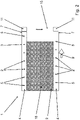
- the device 1 for cultivating and harvesting mushrooms 2 ( 2 ) has a picking frame, whereby in figure 2 example, such a picking frame 3 can be seen from above.
- the on a substrate 16 ( 2 ) growing mushrooms 2 ( 3 ) are arranged on the picking frame 3 in a harvesting level.
- two conveyor belts 4 extend.
- These conveyor belts 4 have recesses 5 which, in the exemplary embodiments, are designed as through-holes formed one behind the other in the conveyor belt 4 .
- the recesses 5 serve to accommodate the substrate 16 ( 2 ) harvested mushrooms 2 ( 3 ), which for example in figure 3 is easy to see.
- the conveyor belts 4 are designed to carry the stem 6 ( figure 5 , 6 and 7 ) In the recess 5 recorded mushrooms 2 to promote.
- a discharge device 7 is arranged on the device 1 at a discharge point of the conveyor belts 4 .
- This ejection device 7 continues the conveying movement of the picked up mushrooms 2 ( 3 ) into a discard motion.
- the ejection device 7 moves the mushroom stalks 6 out of the recess 5, after which the mushrooms 2 are ejected from the conveyor belt 4 under the effect of gravity. This makes it particularly easy, safe and quick to harvest the mushrooms 2 ( 3 ) possible.
- a container conveyor device 15 can also be seen, which is set up to automatically change the containers 11 by removing containers 11 filled with mushrooms 2 and by delivering empty containers 11 .
- the container conveyor device 15 includes a tray stacker of a known type. The removal of the mushrooms 2 ( 3 ) filled containers 11 via a conveyor belt 15 ( 8 ), which promotes the full containers 11 to a collection station.
- the container conveyor device 15 is shown schematically as a simple conveyor belt, which positions the containers 11 under the discharge points of the discharge devices 7 of the two conveyor belts 4 running parallel to the picking frame 3 . It can also be on each side of the picking frame 3 at least two mutually parallel Conveyor belts 4 may be provided to receive the mushrooms 2 harvested from the substrate 16 sorted by size on the conveyor belts 4, with each conveyor belt 4 being assigned at least one discharge device 7.
- the conveyor belts 4 advantageously extend along the entire length of the picking frame 3. This offers the advantage that the pickers harvesting the mushrooms 2 can stand anywhere on either side of the picking frame 3 and can place the picked mushrooms 2 directly on the conveyor belt 4.
- the figure 3 shows a view of a discharge device 7 on a device 1 according to the invention, as also shown in figure 1 is shown.
- the ejection device 7 is designed to drop the mushrooms 2 moved out of the recess 5 into a container 11 under the conveyor belt 4 .
- a container 11 is simply arranged at the discharge point under the conveyor belt 4, so that the mushrooms 2 fall from the conveyor belt 4 into the containers 11 under the action of gravity.
- the mushrooms 2 placed in the recesses 5 are moved in the conveying direction 9 on the conveyor belt 4 .
- the ejection device 7 converts the conveying movement of the mushrooms picked up in the conveying direction 9 on the conveyor belt 4 into a ejection movement.
- the ejection device 7 moves the mushroom stalks 6 out of the recess 5 .
- the mushrooms 2 are thrown off the conveyor belt 4 under the effect of gravity.
- FIG 4 an isolated view of the bucket or ramp 8 is shown.
- the discharge device 7 designed in this way can simply be arranged under a conveyor belt 4 of the device 1 .
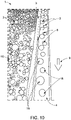
- the figure 5 shows a schematic sectional view through a corresponding spoon or a corresponding ramp 8 at the discharge point under a conveyor belt 4 of the device 1.
- the discharge device 7 in the form of a spoon or a ramp 8 is arranged obliquely in the conveying direction 9 under the conveyor belt 4 .
- the spoon or the ramp 8 is thus arranged in such a way that the mushrooms 2 picked up on the handle 6 are picked up by the discharge device 7 on the handle 6 and the mushrooms 2 at be pushed out of the recess 5 one after the other during the conveying movement.
- the view shows that the left mushroom 2 with its stalk 6 is still completely accommodated in the recess 5 of the conveyor belt 4, just as it was placed on the conveyor belt 4 manually by the pickers.
- the right one of the mushrooms 2 has already reached the discharge point of the conveyor belt 4 as a result of the conveying movement in the conveying direction 9.
- the spoon or the ramp 8 already grips the handle 6 of the right mushroom 2 and pushes it out of the recess 5 in a throwing motion.
- FIG 6 1 is a schematic sectional view through an ejection device 7 designed as a deflection wheel 10 at the ejection point of a conveyor belt 4 .
- the deflection wheel 10 guides the conveyor belt 4 here.
- the deflection wheel 10 can deflect the conveyor belt 4 here, as is indicated by dot-dash lines.
- the deflection wheel 10 can also guide the conveyor belt 4 in that the deflection edge 10 only supports the conveyor belt 4 on the underside.
- the deflection wheel 10 acts on the handle 6 of the mushrooms 2 picked up and pushes the mushrooms 2 out of the recess 5 one after the other during the conveying movement.
- the view shows that the left mushroom 2 with its stalk 6 is still completely accommodated in the recess 5 of the conveyor belt 4, just as the mushroom 2 was placed on the conveyor belt 4 by the pickers by hand.
- the mushroom 2 on the right has already reached the discharge point of the conveyor belt 4 as a result of the conveying movement in the conveying direction 9 .
- the deflection wheel 10 already grips the stalk 6 of the right mushroom 2 and pushes it out of the recess 5 of the conveyor belt 4 in a throwing motion.
- the ejection device 7 thus moves the mushroom stalks 6 out of the recess 5 and the mushrooms 2 fall off the conveyor belt 4 under the effect of gravity.
- the figure 7 shows a schematic sectional view, with an additional deflection edge 10 being provided at the dropping point behind the spoon or the ramp 8 .
- the discharge device 7 comprises a deflection wheel 10 and a spoon or a ramp 8.
- the deflection wheel 10 guides the conveyor belt 4.
- the deflection wheel 10 can deflect the conveyor belt 4, as is indicated by dot-dash lines.
- the deflection wheel 10 can also guide the conveyor belt in that the deflection edge 10 only supports the conveyor belt 4 on the underside.
- the spoon or the ramp 8 is arranged in the conveying direction 9 in front of the deflection wheel 10 under the conveyor belt 4 .
- the spoon or the ramp 8 serves to grip the mushrooms 2 received on the conveyor belt 4 by the stem 6 and to partially push the mushrooms 2 out of the recess 5 during the conveying movement 9 .
- the downstream deflection wheel 10 is used here to then push the mushrooms 2 completely out of the recess 5 .
- the ejection device 7 thus moves the mushroom stalks 6 out of the recess 5 and the mushrooms 2 fall off the conveyor belt 4 under the effect of gravity. In this way, it is prevented in particular that the mushroom stalks are pinched between the conveyor belt 4 and the deflection wheel 10 .
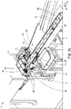
- the figure 8 shows a view of a discharge device 7 on a device 1 according to the invention.
- the discharge device 7 also includes a chute 12.
- the ejection device 7 covers the recesses 5 in the conveyor belt 4 from the underside, so that the mushrooms 2 ( 3 ) cannot fall back into the recesses 5 before they fall off the conveyor belt 4.
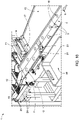
- FIG 9 is the ejection device 7 according to figure 8 shown from a different perspective.
- containers 11, not shown are located under the end of the chute 12 on a scale 14.
- This scale 14 serves to determine the weight of the containers 11 ( 1 ) capture. By determining the weight of the containers 11, conclusions can be drawn about the filling level.
- the scale 14 can give a signal to the restraining device 13 on the chute 12 so that the mushrooms 2 ( 3 ) are retained on the chute 12 when a target weight of mushrooms 2 in a container 11 ( 3 ) on the scale 14 was reached.
- the scales 14 are integrated into a container conveyor device 15 .
- This container conveyor device 15 is set up to transport the containers 11 ( 1 ) each time a weight corresponding to a fraction of a desired weight is detected on the scale 14 in order to ensure that the containers 11 are filled evenly.
- the scales 14 are provided with a conveyor belt 17 which is part of the container conveyor device 15 .
- the figure 10 shows a device 1 for cultivating and harvesting mushrooms 2.
- the picking frame 3 of the device 1 can be seen here, with the mushrooms 2 growing on the substrate 16 being arranged on the picking frame 3 in a harvesting plane.
- a conveyor belt 4 which has recesses 5 for receiving the mushrooms 2 harvested from the substrate 16 extends along the picking frame 3 .
- the mushrooms 2 picked up on the conveyor belt 4 are conveyed in the conveying direction 9 with the stalk in the recess 5 .
- the conveyor belt 4 has at least two rows 18 with recesses 5 in order to accommodate the mushrooms 2 harvested from the substrate 16, sorted according to size and divided between the at least two rows 18.
- the two rows 18 with recesses 5 along the extension of the conveyor belt 4 allow the pickers to allocate the mushrooms 2 to the individual rows 18 on the conveyor belt 4 depending on their size. In this way, the pickers can immediately sort by size during the harvest.
- FIG 11 is a discharge device 7 with chute 12 at the end of the conveyor belt 4 according to figure 10 shown.
- the mushrooms 2 reach the ejection device 7 sorted according to size and divided into at least two rows 18 .
- the mushrooms 2 of different sizes are conveyed into different containers 11 at the discharge points via a two-part chute 12 on the discharge device 7 .
- the ejection device 7 converts the conveying movement of the picked-up mushrooms 2 into an ejection movement, as in the other embodiments.
- the mushroom stalks 6 are thus moved out of the recesses 5 by the ejection device 7 , after which the mushrooms 2 are ejected from the conveyor belt 4 under the effect of gravity and fall from the chute 12 divided into different containers 11 .
- Two light barriers can also be provided on the chute 12 . These light barriers are set up to detect the individual mushrooms 2 so that they can be counted. In combination with two scales, which weigh the mushrooms 2 located in the containers 11, an average weight of the individual mushrooms 2 in the containers 11 can be easily determined from the number of mushrooms 2.
- the figure 12 shows a device 1 according to the invention for cultivating and harvesting mushrooms 2 ( 2 ).
- the device 1 has a picking frame, in which figure 2 example, such a picking frame 3 can be seen from above.
- the device 1 has a conveyor belt 4 that extends along the picking frame 3 and has recesses 5 for receiving the material picked off the substrate 16 ( 2 ) harvested mushrooms 2 ( 3 ) has,
- the conveyor belt 4 is also designed here to carry the stem 6 ( figure 5 , 6 and 7 ) In the recess 5 recorded mushrooms 2 to promote.
- a discharge device 7 is arranged on the device 1 at a discharge point of the conveyor belt 4 . This ejection device 7 continues the conveying movement of the picked up mushrooms 2 ( 3 ) into a discard motion.
- the ejection device 7 moves the mushroom stalks 6 ( figure 5 ) out of the recess 5, after which the mushrooms 2 ( 3 ) are thrown off the conveyor belt 4 under the action of gravity.
- This allows a simple, safe and quick harvest of the mushrooms 2 ( 3 ) can be reached.
- a container conveyor device 15 can also be seen, which is set up to automatically change the containers 11 by removing containers 11 filled with mushrooms 2 and by delivering empty containers 11 .
- the container conveyor device 15 includes a tray stacker of a known type. The removal of the mushrooms 2 ( 3 ) filled containers 11 via a conveyor belt 15, which promotes the full containers 11 to a collection station.
- sieve belts 19 are now additionally provided, on which the mushrooms 2 moved out of the recesses 5 strike under the effect of gravity, with the sieve belts 19 being designed so that adhering substrate is separated from the mushrooms 2 that hit it and through the sieve belts 19 falls, while the mushrooms 2 fall freely from the separated substrate from the sieve belts 19 further into containers 11.
- the fungi can be freed from adhering substrate very easily in an automated manner, because the substrate falls off the fungi hitting the screen belts 19 and through the screen belts 19 and can be collected under the screen belts 19, for example in a collecting pan.
- marked recesses 20 can be seen on the conveyor belt 4 in order to allocate the mushrooms harvested from the substrate, sorted according to quality, to the marked recesses 20 and the regular recesses.
- an ejection device 21 can be seen, which can move mushrooms 2 harvested from the substrate out of the marked recesses 20 and conveys the mushrooms separated in the marked recesses 20 into a separate collection container 22 .
- a separate collection container 22 can be seen, preferably every fifth recess 20 in a row 18 on the conveyor belt 4 is marked.
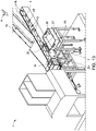
- FIG 13 is a further view of the ejection device 7 according to FIG figure 12 shown.
- the ejection device 7 includes two slides 12, via which the Discharge device 7 from the recess 5 moving out mushrooms 2 slip under the action of gravity on the screen belts 19.
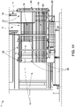
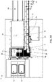
- the figure 14 shows a view from above of the sieve belts 19, on which the sorted by size and on two rows 18 ( 12 ) divided mushrooms are dropped from the conveyor belt 4.
- the mushrooms 2 of different sizes then hit different sieve belts 19 via a two-part chute 12 on the discharge device 7 and are conveyed into different containers 11 after the adhering substrate has been separated.
- the screen belts 19 are formed by belts 24 with a round cross section, preferably made of rubber, which are guided on deflection shafts 25 at a distance from one another and form endless conveyor belts of a screen belt 19 .
- the chutes 12 and screen belts 19 are of different lengths, so that on the one hand the mushrooms from the two rows 18 can hit the two screen belts which are oriented transversely to the conveying direction 9 and are arranged next to one another.
- the screen belts 19 are of different lengths so that two containers 11 arranged next to one another in the conveying direction 9 can be filled via the screen belts 19 .
- the containers 11 are provided under the sieve belts 19 via a container conveyor device 15 which is set up to automatically change the containers 11 by removing containers 11 filled with mushrooms 2 and by delivering empty containers 11 .
- the containers 11 are located under the end of the sieve belts 19 on a scale 14.
- This scale 14 is used to record the weight of the containers 11 parked. By determining the weight of the containers 11, conclusions can be drawn about the filling level. As a result, the scales 14 can be used to identify whether a container 11 under the discharge point of the discharge device 7 is already sufficiently full and whether a change to a container 11 that is still empty is required.
- the scales 14 can give a signal to a restraining device 13 on the chute 12, so that the mushrooms 2 are retained on the chute 12, or the scales 14 can give a signal to a control of the sieve belts 19, so that they are (briefly) stopped when a target weight of mushrooms 2 in a container 11 on the scale 14 has been reached.
- the scales 14 are integrated into a container conveyor device 15 .
- This container conveyor device 15 is preferably set up to move the containers 11 piece by piece when a weight corresponding to a fraction of a target weight is detected on the scale 14 in order to ensure that the containers 11 are filled evenly.
- the scales 14 are provided with a conveyor belt 17 which is part of the container conveyor device 15 .
- the ejection device 21, which collects mushrooms 2 ( 3 ) can move out of the marked recesses 20 and the mushrooms 2 ( 3 ) conveyed into a separate collection container 22.
- the separate collection container 22 stands laterally next to the conveyor belt 4 on the storage table 24, so that the ejection device 21 separates the mushrooms 2 ( 3 ) can carry into the collection container 22.
- the conveyor belt 4 has marked recesses 20 in order to accommodate the mushrooms 2 harvested from the substrate, sorted according to quality, in the marked recesses 20.
- a third quality level can also be separated in a simple manner.
- the ejection device 21 moves the mushrooms harvested and separated from the substrate out of the marked recesses 20 into the separate collection container 22.
- the ejection device 21 is advantageously designed as a lever.
- the figure 18 shows the area around the ejector 21 from above. It can be seen here that the lever 21 swings out in good time before the marked recess into the gripping position shown over the conveyor belt 4 in order to move mushrooms that have been separated in the marked recesses 20 off the conveyor belt 4 .
- the ejection device 21 advantageously has a sensor for detecting colors of the conveyor belt 4, the marked recesses 20 on the conveyor belt 4 being marked in color. The sensor is set up to emit a signal in order to actuate the ejection device 21 when a color-coded recess 20 is detected, so that the lever 21 is pivoted into the gripping position and then pivoted back into the ejection position.
- FIG. 19 and 20 show that the discharge device 7 arranged at the discharge point of the conveyor belt 4, the mushrooms 2 ( 3 ) throws off the conveyor belt 4 from the two rows 18 under the effect of gravity, which then slide separately onto the two screen belts 19 on two chutes 12 .
- Adhering substrate falls through the sieve belts 19 and the mushrooms are transported from here into the waiting containers 11 under the sieve belts 19 .
- Filled containers 11 are then automatically transported away via the container conveyor device 15 and empty containers 11 are automatically made available.
Landscapes
- Engineering & Computer Science (AREA)
- Mechanical Engineering (AREA)
- Life Sciences & Earth Sciences (AREA)
- Mycology (AREA)
- Environmental Sciences (AREA)
- Microelectronics & Electronic Packaging (AREA)
- Agronomy & Crop Science (AREA)
- Quality & Reliability (AREA)
- Sorting Of Articles (AREA)
- Mushroom Cultivation (AREA)
- Specific Conveyance Elements (AREA)
Priority Applications (4)
| Application Number | Priority Date | Filing Date | Title |
|---|---|---|---|
| RS20250783A RS67107B1 (sr) | 2021-05-28 | 2022-04-28 | Uređaj za gajenje i branje pečuraka |
| EP24221851.9A EP4559310A3 (fr) | 2021-05-28 | 2022-04-28 | Dispositif de culture et de récolte des champignons |
| SM20250300T SMT202500300T1 (it) | 2021-05-28 | 2022-04-28 | Sistema per coltivare e raccogliere funghi |
| HRP20250961TT HRP20250961T1 (hr) | 2021-05-28 | 2022-04-28 | Uređaj za uzgajanje i branje gljiva |
Applications Claiming Priority (3)
| Application Number | Priority Date | Filing Date | Title |
|---|---|---|---|
| DE102021113916 | 2021-05-28 | ||
| DE102021114939.8A DE102021114939B4 (de) | 2021-05-28 | 2021-06-10 | Vorrichtung zur Kultivierung und Ernte von Pilzen |
| DE202021105746.7U DE202021105746U1 (de) | 2021-05-28 | 2021-10-20 | Vorrichtung zur Kultivierung und Ernte von Pilzen |
Related Child Applications (2)
| Application Number | Title | Priority Date | Filing Date |
|---|---|---|---|
| EP24221851.9A Division EP4559310A3 (fr) | 2021-05-28 | 2022-04-28 | Dispositif de culture et de récolte des champignons |
| EP24221851.9A Division-Into EP4559310A3 (fr) | 2021-05-28 | 2022-04-28 | Dispositif de culture et de récolte des champignons |
Publications (3)
| Publication Number | Publication Date |
|---|---|
| EP4094571A1 true EP4094571A1 (fr) | 2022-11-30 |
| EP4094571C0 EP4094571C0 (fr) | 2025-06-04 |
| EP4094571B1 EP4094571B1 (fr) | 2025-06-04 |
Family
ID=81393045
Family Applications (2)
| Application Number | Title | Priority Date | Filing Date |
|---|---|---|---|
| EP22170515.5A Active EP4094571B1 (fr) | 2021-05-28 | 2022-04-28 | Dispositif de culture et de récolte des champignons |
| EP24221851.9A Pending EP4559310A3 (fr) | 2021-05-28 | 2022-04-28 | Dispositif de culture et de récolte des champignons |
Family Applications After (1)
| Application Number | Title | Priority Date | Filing Date |
|---|---|---|---|
| EP24221851.9A Pending EP4559310A3 (fr) | 2021-05-28 | 2022-04-28 | Dispositif de culture et de récolte des champignons |
Country Status (7)
| Country | Link |
|---|---|
| EP (2) | EP4094571B1 (fr) |
| ES (1) | ES3036605T3 (fr) |
| HR (1) | HRP20250961T1 (fr) |
| HU (1) | HUE072281T2 (fr) |
| PL (1) | PL4094571T3 (fr) |
| RS (1) | RS67107B1 (fr) |
| SM (1) | SMT202500300T1 (fr) |
Cited By (1)
| Publication number | Priority date | Publication date | Assignee | Title |
|---|---|---|---|---|
| US20240217687A1 (en) * | 2021-07-22 | 2024-07-04 | Confirmed Automation Systems Inc. | Mushroom packing apparatus |
Citations (3)
| Publication number | Priority date | Publication date | Assignee | Title |
|---|---|---|---|---|
| DE102015105606A1 (de) | 2015-04-13 | 2016-10-13 | Pilzkulturen Wesjohann GbR ( vertretungsber. Gesellsch. Erich Wesjohann, Dirk Wesjohann, Jan Wesjohann, Anne Wesjohann, 49429 Visbek) | System zum Ernten von Pilzen |
| EP3750394A1 (fr) * | 2019-05-21 | 2020-12-16 | Pilzkulturen Wesjohann GbR | Système de culture et de récolte de champignons |
| EP3815518A2 (fr) * | 2019-11-01 | 2021-05-05 | Jacobus Alexander Jozef Lemmen | Dispositif de transport et de déchargement de champignons |
-
2022
- 2022-04-28 PL PL22170515.5T patent/PL4094571T3/pl unknown
- 2022-04-28 RS RS20250783A patent/RS67107B1/sr unknown
- 2022-04-28 ES ES22170515T patent/ES3036605T3/es active Active
- 2022-04-28 SM SM20250300T patent/SMT202500300T1/it unknown
- 2022-04-28 EP EP22170515.5A patent/EP4094571B1/fr active Active
- 2022-04-28 HR HRP20250961TT patent/HRP20250961T1/hr unknown
- 2022-04-28 EP EP24221851.9A patent/EP4559310A3/fr active Pending
- 2022-04-28 HU HUE22170515A patent/HUE072281T2/hu unknown
Patent Citations (3)
| Publication number | Priority date | Publication date | Assignee | Title |
|---|---|---|---|---|
| DE102015105606A1 (de) | 2015-04-13 | 2016-10-13 | Pilzkulturen Wesjohann GbR ( vertretungsber. Gesellsch. Erich Wesjohann, Dirk Wesjohann, Jan Wesjohann, Anne Wesjohann, 49429 Visbek) | System zum Ernten von Pilzen |
| EP3750394A1 (fr) * | 2019-05-21 | 2020-12-16 | Pilzkulturen Wesjohann GbR | Système de culture et de récolte de champignons |
| EP3815518A2 (fr) * | 2019-11-01 | 2021-05-05 | Jacobus Alexander Jozef Lemmen | Dispositif de transport et de déchargement de champignons |
Cited By (1)
| Publication number | Priority date | Publication date | Assignee | Title |
|---|---|---|---|---|
| US20240217687A1 (en) * | 2021-07-22 | 2024-07-04 | Confirmed Automation Systems Inc. | Mushroom packing apparatus |
Also Published As
| Publication number | Publication date |
|---|---|
| RS67107B1 (sr) | 2025-09-30 |
| PL4094571T3 (pl) | 2025-11-24 |
| EP4559310A2 (fr) | 2025-05-28 |
| HRP20250961T1 (hr) | 2025-10-10 |
| ES3036605T3 (en) | 2025-09-22 |
| EP4094571C0 (fr) | 2025-06-04 |
| EP4559310A3 (fr) | 2025-06-18 |
| SMT202500300T1 (it) | 2025-09-12 |
| EP4094571B1 (fr) | 2025-06-04 |
| HUE072281T2 (hu) | 2025-11-28 |
Similar Documents
| Publication | Publication Date | Title |
|---|---|---|
| DE102021114939B4 (de) | Vorrichtung zur Kultivierung und Ernte von Pilzen | |
| EP3081071B1 (fr) | Systeme de recolte de champignons | |
| EP3750394B1 (fr) | Système de culture et de récolte de champignons | |
| DE69733275T2 (de) | Pflanzmaschine | |
| EP3097764B1 (fr) | Système de culture et de récolte de champignons | |
| EP3246272B1 (fr) | Glissière et dispositif de tri et procédé de tri de marchandise au détail | |
| EP2936986B1 (fr) | Machine à chachlyks et procédé de production de chachlyks | |
| CH428548A (de) | Eier-Transport- und Verpackungs- Vorrichtung | |
| WO1994018823A1 (fr) | Systeme d'elevage de volaille dans des batteries de cages | |
| EP1106048A1 (fr) | Dispositif d'introduction et de cueillage d'un dispositif de chargement de récoltes | |
| DE102021119720A1 (de) | Verfahren zum Lage-genauen Ablegen einer Portion oder deren Teilen sowie hierfür geeignete Ablage-Vorrichtung | |
| US6257978B1 (en) | Food plant harvester with improved recovery system | |
| EP4094571B1 (fr) | Dispositif de culture et de récolte des champignons | |
| DE4039417C2 (de) | Vorrichtung zur Aufnahme und Übergabe von druckempfindlichen Stückgütern für eine Verbund-Wiegemaschine | |
| DE102022111382A1 (de) | Greifvorrichtung für stangenförmige Lebensmittel, Roboter mit einer derartigen Greifvorrichtung sowie Vorrichtung mit einem derartigen Roboter | |
| US6708474B2 (en) | Single pass tobacco harvester and method | |
| DE3910230C1 (en) | Apparatus for collecting, transporting and discharging mushrooms | |
| EP1620315A1 (fr) | Dispositif d'emballage de recipients rigides ouverts d'un cote | |
| DE19955222A1 (de) | Verfahren und Vorrichtung zum Verarbeiten und Verpacken von Pilzen o. dgl. | |
| DE2050654C3 (de) | Vorrichtung zum automatischen Bearbeiten von Pilzen | |
| DE102010017045B4 (de) | Verfahren zum Abtrennen von Rebenabschnitten vorbestimmter Länge, Rebenvorschneidesystem sowie eine damit versehene Hopfenpflückmaschine | |
| EP1994816A1 (fr) | Récolteuse | |
| EP3987908A1 (fr) | Récolteuse pour simultanément déposer deux collecteur de grain pour la détermination de perte de grain | |
| DE102020128110A1 (de) | Ablagevorrichtung | |
| DE102023123172A1 (de) | Spargelsortiermaschine und Verfahren |
Legal Events
| Date | Code | Title | Description |
|---|---|---|---|
| REG | Reference to a national code |
Ref country code: HR Ref legal event code: TUEP Ref document number: P20250961T Country of ref document: HR |
|
| PUAI | Public reference made under article 153(3) epc to a published international application that has entered the european phase |
Free format text: ORIGINAL CODE: 0009012 |
|
| STAA | Information on the status of an ep patent application or granted ep patent |
Free format text: STATUS: THE APPLICATION HAS BEEN PUBLISHED |
|
| AK | Designated contracting states |
Kind code of ref document: A1 Designated state(s): AL AT BE BG CH CY CZ DE DK EE ES FI FR GB GR HR HU IE IS IT LI LT LU LV MC MK MT NL NO PL PT RO RS SE SI SK SM TR |
|
| STAA | Information on the status of an ep patent application or granted ep patent |
Free format text: STATUS: REQUEST FOR EXAMINATION WAS MADE |
|
| 17P | Request for examination filed |
Effective date: 20230523 |
|
| RBV | Designated contracting states (corrected) |
Designated state(s): AL AT BE BG CH CY CZ DE DK EE ES FI FR GB GR HR HU IE IS IT LI LT LU LV MC MK MT NL NO PL PT RO RS SE SI SK SM TR |
|
| GRAP | Despatch of communication of intention to grant a patent |
Free format text: ORIGINAL CODE: EPIDOSNIGR1 |
|
| STAA | Information on the status of an ep patent application or granted ep patent |
Free format text: STATUS: GRANT OF PATENT IS INTENDED |
|
| RIC1 | Information provided on ipc code assigned before grant |
Ipc: A01D 46/00 20060101ALI20241122BHEP Ipc: B65B 1/32 20060101ALI20241122BHEP Ipc: B65G 15/28 20060101ALI20241122BHEP Ipc: A01G 18/70 20180101ALI20241122BHEP Ipc: A01G 18/60 20180101AFI20241122BHEP |
|
| INTG | Intention to grant announced |
Effective date: 20241204 |
|
| GRAS | Grant fee paid |
Free format text: ORIGINAL CODE: EPIDOSNIGR3 |
|
| GRAA | (expected) grant |
Free format text: ORIGINAL CODE: 0009210 |
|
| STAA | Information on the status of an ep patent application or granted ep patent |
Free format text: STATUS: THE PATENT HAS BEEN GRANTED |
|
| AK | Designated contracting states |
Kind code of ref document: B1 Designated state(s): AL AT BE BG CH CY CZ DE DK EE ES FI FR GB GR HR HU IE IS IT LI LT LU LV MC MK MT NL NO PL PT RO RS SE SI SK SM TR |
|
| REG | Reference to a national code |
Ref country code: GB Ref legal event code: FG4D Free format text: NOT ENGLISH |
|
| REG | Reference to a national code |
Ref country code: CH Ref legal event code: EP |
|
| REG | Reference to a national code |
Ref country code: DE Ref legal event code: R096 Ref document number: 502022004123 Country of ref document: DE |
|
| REG | Reference to a national code |
Ref country code: IE Ref legal event code: FG4D Free format text: LANGUAGE OF EP DOCUMENT: GERMAN |
|
| U01 | Request for unitary effect filed |
Effective date: 20250703 |
|
| U07 | Unitary effect registered |
Designated state(s): AT BE BG DE DK EE FI FR IT LT LU LV MT NL PT RO SE SI Effective date: 20250710 |
|
| REG | Reference to a national code |
Ref country code: ES Ref legal event code: FG2A Ref document number: 3036605 Country of ref document: ES Kind code of ref document: T3 Effective date: 20250922 |
|
| REG | Reference to a national code |
Ref country code: HR Ref legal event code: T1PR Ref document number: P20250961 Country of ref document: HR |
|
| REG | Reference to a national code |
Ref country code: SK Ref legal event code: T3 Ref document number: E 47049 Country of ref document: SK |
|
| REG | Reference to a national code |
Ref country code: GR Ref legal event code: EP Ref document number: 20250401657 Country of ref document: GR Effective date: 20251009 |
|
| REG | Reference to a national code |
Ref country code: HU Ref legal event code: AG4A Ref document number: E072281 Country of ref document: HU |
|
| PGFP | Annual fee paid to national office [announced via postgrant information from national office to epo] |
Ref country code: SM Payment date: 20260327 Year of fee payment: 5 |
|
| PLBE | No opposition filed within time limit |
Free format text: ORIGINAL CODE: 0009261 |
|
| STAA | Information on the status of an ep patent application or granted ep patent |
Free format text: STATUS: NO OPPOSITION FILED WITHIN TIME LIMIT |
|
| REG | Reference to a national code |
Ref country code: CH Ref legal event code: L10 Free format text: ST27 STATUS EVENT CODE: U-0-0-L10-L00 (AS PROVIDED BY THE NATIONAL OFFICE) Effective date: 20260416 |