EP4094691A1 - Système radiographique, dispositif de commande et procédé de commande de système radiographique - Google Patents
Système radiographique, dispositif de commande et procédé de commande de système radiographique Download PDFInfo
- Publication number
- EP4094691A1 EP4094691A1 EP21764403.8A EP21764403A EP4094691A1 EP 4094691 A1 EP4094691 A1 EP 4094691A1 EP 21764403 A EP21764403 A EP 21764403A EP 4094691 A1 EP4094691 A1 EP 4094691A1
- Authority
- EP
- European Patent Office
- Prior art keywords
- radiation
- irradiation
- dose
- time
- threshold
- Prior art date
- Legal status (The legal status is an assumption and is not a legal conclusion. Google has not performed a legal analysis and makes no representation as to the accuracy of the status listed.)
- Pending
Links
Images


Classifications
-
- A—HUMAN NECESSITIES
- A61—MEDICAL OR VETERINARY SCIENCE; HYGIENE
- A61B—DIAGNOSIS; SURGERY; IDENTIFICATION
- A61B6/00—Apparatus or devices for radiation diagnosis; Apparatus or devices for radiation diagnosis combined with radiation therapy equipment
- A61B6/54—Control of apparatus or devices for radiation diagnosis
- A61B6/542—Control of apparatus or devices for radiation diagnosis involving control of exposure
-
- A—HUMAN NECESSITIES
- A61—MEDICAL OR VETERINARY SCIENCE; HYGIENE
- A61B—DIAGNOSIS; SURGERY; IDENTIFICATION
- A61B6/00—Apparatus or devices for radiation diagnosis; Apparatus or devices for radiation diagnosis combined with radiation therapy equipment
- A61B6/10—Safety means specially adapted therefor
- A61B6/107—Protection against radiation, e.g. shielding
-
- A—HUMAN NECESSITIES
- A61—MEDICAL OR VETERINARY SCIENCE; HYGIENE
- A61B—DIAGNOSIS; SURGERY; IDENTIFICATION
- A61B6/00—Apparatus or devices for radiation diagnosis; Apparatus or devices for radiation diagnosis combined with radiation therapy equipment
- A61B6/40—Arrangements for generating radiation specially adapted for radiation diagnosis
- A61B6/4035—Arrangements for generating radiation specially adapted for radiation diagnosis the source being combined with a filter or grating
-
- A—HUMAN NECESSITIES
- A61—MEDICAL OR VETERINARY SCIENCE; HYGIENE
- A61B—DIAGNOSIS; SURGERY; IDENTIFICATION
- A61B6/00—Apparatus or devices for radiation diagnosis; Apparatus or devices for radiation diagnosis combined with radiation therapy equipment
- A61B6/42—Arrangements for detecting radiation specially adapted for radiation diagnosis
Definitions
- a disclosure of a present specification relates to a radiation imaging system for performing a radiation imaging and a method for controlling the same.
- radiation imaging apparatuses equipped with a flat panel detector (FPD) formed of a semiconductor material are widely used as radiation imaging apparatuses used for medical imaging diagnosis and nondestructive examination using radiation such as X-ray.
- a radiation imaging apparatus is used, for example, as a digital radiation imaging apparatus for taking still images such as general photographing and for taking moving images such as fluoroscopy in medical image diagnosis.
- Some radiation imaging apparatuses monitor the dose of irradiated radiation (accumulated dose) and stop the irradiation of the radiation when the accumulated dose reaches a threshold (for example, an irradiation stop signal for stopping the irradiation of the radiation is output to a radiation generator.).
- a threshold for example, an irradiation stop signal for stopping the irradiation of the radiation is output to a radiation generator.
- This operation is called Automatic Exposure Control (AEC), which can prevent, for example, excessive irradiation of the radiation.
- AEC Automatic Exposure Control
- PTL1 discloses a radiation imaging apparatus including a dose detection unit for detecting a dose of the radiation reaching an imaging area, in the imaging area of the FPD.
- the stopping timing at which the irradiation of the radiation should be stopped in the radiation generator is predicted based on the dose detected by the dose detection unit and a dose target value set in advance, and the irradiation stopping timing notification for informing the radiation generator of the irradiation stopping timing of the radiation is transmitted before the irradiation stopping timing arrives.
- the technique disclosed in PTL1 has a problem in the accuracy of an irradiation stop control of the radiation from the radiation generator.
- the time required for the accumulated dose of the radiation to reach the threshold is shortened to about several ms (milliseconds), and as a result, the accumulated dose of the radiation becomes larger than the threshold before the radiation generator stops the irradiation due to the delay in the notification of the irradiation stop timing.
- a radiation imaging apparatus disclosed herein comprises: a sensor unit configured to detect an incident radiation irradiated from a radiation generator; an arithmetic unit configured to calculate an accumulated dose of the radiation detected by the sensor unit; and a control unit configured to output an irradiation stop signal for stopping the irradiation of the radiation to the radiation generator when the accumulated dose reaches a threshold or more, wherein the control unit sets the threshold based on a dose rate of the radiation determined based on a relationship between the accumulated dose and a time, and a delay time from a time of outputting the irradiation stop signal to a time of stopping the irradiation of the radiation of the radiation generator.
- the disclosure also includes methods for controlling the radiation imaging system described above.
- the purpose of the disclosure of the present specification is not limited to one of the above-described purposes.
- One of the other purposes of the present invention is to provide working effects derived from the respective configurations shown in the embodiments to be described later as an embodiment for carrying out the disclosure, which cannot be obtained by the prior art.
- the radiation is not limited to the X-ray, and it is assumed that ⁇ -rays, ⁇ -rays, ⁇ -rays and the like are also included in the radiation to be used.
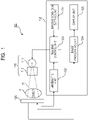
- FIG. 1 is a diagram showing an example of a schematic configuration of a radiation imaging system 100 according to a first embodiment.
- the radiation imaging system 100 is particularly suitable for medical use.
- the radiation imaging system 100 is configured by including a radiation generator 110, a radiation imaging device 120, and a control unit 130.
- the control unit 130 is configured to be capable of communicating with the radiation generator 110 and the radiation imaging device 120, and includes an imaging condition setting unit 131, an arithmetic unit 132, an imaging control unit 133, an image processing unit 134, and a display unit 135.
- the radiation generator 110 irradiates the object P with the radiation R under a control of the control unit 130 (more specifically, the imaging control unit 133.).
- the radiation generator 110 includes a radiation tube 111 which is a radiation generator unit for generating the radiation R, and a collimator 112 which defines a beam spreading angle of the radiation R generated by the radiation tube 111.
- the radiation imaging device 120 includes, for example, an FPD, and includes a sensor unit including an imaging element distributed in two dimensions.
- the sensor unit detects the incident radiation R irradiated from the radiation generator 110.
- the radiation imaging device 120 specifically detects information (dose information) on the two-dimensional distribution of the radiation dose that has reached the imaging elements in the sensor unit, and generates radiation image data. Thereafter, the radiation imaging device 120 transmits the generated radiation image data to the image processing unit 134 of the control unit 130.
- the radiation imaging device 120 transmits information (dose information) on the two-dimensional distribution of the radiation dose detected by the sensor unit to the arithmetic unit 132 of the control unit 130.
- the control unit 130 controls operations of the radiation generator 110 and the radiation imaging device 120, and acquires and processes dose information detected by the sensor unit of the radiation imaging device 120 and radiation image data imaged by the radiation imaging device 120.
- the imaging condition setting unit 131 sets imaging condition data including, for example, imaging condition information such as an imaging region of the object P, the tube voltage and tube current in the radiation tube 111, a delay time, a reference value Dref of the dose (accumulated dose) at which the radiation R passes through the object P and reaches the radiation imaging device 120, and a threshold Dth for controlling an output of the irradiation stop signal to the radiation generator 110, which are input by an operator. Then, the imaging condition setting unit 131 transmits necessary imaging condition information among the set imaging condition data to the imaging control unit 133.
- the dose generally means the accumulated dose achieved at the time of an irradiation of the radiation, but a dose value similar thereto may be used, and the term of "accumulated dose" will be used in the following, if necessary.
- the arithmetic unit 132 calculates the accumulated dose of the radiation R detected by the sensor unit of the radiation imaging device 120 based on the dose information transmitted from the radiation imaging device 120, and transmits the calculated accumulated dose to the imaging control unit 133.
- the imaging control unit 133 controls the radiation generator 110 and the radiation imaging device 120 based on the imaging condition information received from the imaging condition setting unit 131 and information of the accumulated dose received from the arithmetic unit 132.
- the image processing unit 134 performs image processing such as gradation processing and noise reduction processing on the radiation image data transmitted from the radiation imaging device 120. Then, the image processing unit 134 transmits the radiation image data after the image processing to the display unit 135.
- the display unit 135 outputs a radiation image based on the radiation image data transmitted from the image processing unit 134 to a monitor or the like to display it.
- the delay time set by the imaging condition setting unit 131 is a time period from a time when an irradiation stop signal for stopping the irradiation of the radiation R is outputted from the imaging control unit 133 to the radiation generator 110 based on the accumulated dose of the radiation R calculated by the arithmetic unit 132 to a time when the irradiation of the radiation R is stopped in the radiation generator 110.
- the time at which the irradiation of the radiation R is stopped in the radiation generator 110 is a time at which the tube voltage in the radiation tube 111 of the radiation generator 110 starts to decrease or a time at which the tube voltage completely decreases.
- the delay time is set based on the time when the tube voltage in the radiation tube 111 of the radiation generator 110 completely falls, it is desirable to set the delay time by considering the time obtained by multiplying the time of the unsteady period from the time when the tube voltage in the radiation tube 111 starts to fall to the time when the tube voltage in the radiation tube completely falls by a coefficient considering the change in dose and radiation quality.
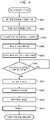
- FIG. 2 is a flowchart showing an example of a processing procedure in a series of control methods from a start to an end of pre-imaging performed before the irradiation of the radiation R for the main-imaging of the object P in the radiation imaging system 100 according to the first embodiment disclosed herein.
- FIG. 3 is a diagram for explaining the series of control methods from the start to the end of pre-imaging of the object P before the irradiation of the radiation R for the main-imaging in the radiation imaging system 100 according to the first embodiment disclosed herein.
- FIG. 3 shows the relationship between the accumulated dose D (vertical axis) and time (horizontal axis).
- the transmitted dose rate of the radiation R which passes through the object P and reaches the radiation imaging device 120 is estimated to at least one of the tube voltage and the tube current in the radiation tube 111 set in each pre-imaging (in this embodiment, for example, each of the tube voltages and each of the tube currents are assumed.), and the estimated dose rate is stored in a database for use in setting a threshold at the time of main-imaging together with a delay time Td shown in FIG. 3 .
- the imaging condition setting unit 131 receives an instruction to start a pre-imaging inputted by an operator via an input unit (not shown), and sets imaging condition information (irradiation condition information) inputted by the operator, for example.
- the imaging condition setting unit 131 sets, as the imaging condition information (irradiation condition information), a tube voltage and a tube current in the radiation tube 111, a reference value Dref of the accumulated dose, a threshold Dth, and the like.
- the imaging condition setting unit 131 sets the threshold Dth equal to the reference value Dref of the accumulated dose, as shown in FIG. 3 .
- the imaging condition setting unit 131 transmits the acquired instruction for starting the pre-imaging and the set imaging condition information (irradiation condition information) to the imaging control unit 133.
- step S202 the imaging control unit 133 transmits an irradiation execution signal for irradiating the radiation R to the radiation generator 110 together with the imaging condition information (irradiation condition information) received from the imaging condition setting unit 131 in step S201. Accordingly, the radiation generator 110 irradiates the radiation R toward the radiation imaging device 120 under the irradiation conditions based on the imaging condition information (irradiation condition information) set in step S201.
- the arithmetic unit 132 calculates a value D representing the accumulated dose of the radiation R detected by the sensor unit based on the dose information (for example, dose information for each imaging element in the sensor unit) transmitted from the radiation imaging device 120.
- the value D representing the accumulated dose of the radiation R may be a maximum value, an average value, a median value or the like of the accumulated dose.
- the value D representing the accumulated dose of the radiation R is described as "accumulated dose D of the radiation R".
- the arithmetic unit 132 transmits the calculated accumulated dose D of the radiation R to the imaging control unit 133.
- the imaging control unit 133 compares the accumulated dose D of the radiation R received from the arithmetic unit 132 with the threshold Dth set in step S201, and determines whether or not the accumulated dose D is smaller than the threshold Dth. As a result of this determination, if the accumulated dose D is smaller than the threshold Dth (step S203/YES), the process waits in step S203.
- step S203 determines whether the accumulated dose D is not smaller than the threshold Dth (that is, the accumulated dose D is equal to or larger than the threshold) (step S203/NO).
- the imaging control unit 133 calculates a dose rate of the radiation R to be irradiated to the radiation imaging device 120 based on the accumulated dose D of the radiation R received from the arithmetic unit 132 in step S203 and the irradiation time of the radiation R.
- the imaging control unit 133 calculates a dose rate of the radiation R to be irradiated to the radiation imaging device 120 based on the accumulated dose D of the radiation R received from the arithmetic unit 132 in step S203 and the irradiation time of the radiation R.
- the imaging control unit 133 estimates a transmitted dose rate of the radiation R based on the dose rate of the radiation R acquired in step S204 and the transmission rate assumed for the object P.
- the transmission rate assumed for the object P may be obtained based on a radiation shield information such as filter condition information relating to a filter simulating a human body at the time of the irradiation of the radiation R in step S202 and object information including the transmittance of a general human body.
- the transmittance assumed for the object P the transmittance of a general human body may be calculated by referring to the imaging data in the past.
- the transmitted dose rate of the radiation R estimated in step S205 is stored in the database in correspondence with the tube voltage and tube current in the radiation tube 111, which is the imaging condition information, and the filter condition information and/or the object information.
- step S206 the imaging control unit 133 obtains the delay time Td shown in FIG. 3 .
- the delay time Td may be actually measured and obtained.
- the delay time Td obtained in step S206 is stored in the database in the same manner as the transmitted dose rate of the radiation R calculated and stored in step S205.
- step S207 the imaging control unit 133 determines whether or not a settable imaging condition (irradiation condition) still exists. As a result of this determination, if there is still a settable imaging condition (irradiation condition) (step S207/YES), the process returns to step S201, and the processing after step S201 are performed for the settable imaging condition (irradiation condition).
- step S207/NO the process of the flowchart relating to the pre-imaging shown in FIG. 2 is ended.
- the transmitted dose rate and the delay time Td of the radiation R can be calculated for each of the imaging condition information such as the tube voltage and the tube current in the radiation tube 111 and for each of the radiation shield information such as the filter condition information and the object information.
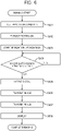
- FIG. 4 is a flowchart showing an example of a processing procedure in a series of control methods from a start to an end of main-imaging of the object P in the radiation imaging system 100 according to the first embodiment.
- FIG. 5 is a diagram for explaining the series of control methods from the start to the end of main-imaging of the object P in the radiation imaging system 100 according to the first embodiment.
- FIG. 5 shows the relationship between accumulated dose D (vertical axis) and time (horizontal axis).
- the irradiation dose ( FIG. 5 ) due to the delay time Td is estimated using various information acquired in the prior pre-imaging process described with reference to FIGS. 2 and 3 , and reflected in the setting of the threshold Dth shown in FIG. 5 to perform the radiation imaging of the object P.
- the imaging condition setting unit 131 receives an instruction to start the main-imaging inputted by the operator via the input unit (not shown), and sets imaging condition information (irradiation condition information) inputted by the operator, for example.
- the imaging condition setting unit 131 sets, as imaging condition information (irradiation condition information), a tube voltage and a tube current in the radiation tube 111, a reference value Dref of the accumulated dose, and the like.
- the imaging condition setting unit 131 transmits the acquired instruction for starting the main-imaging and the set imaging condition information (irradiation condition information) to the imaging control unit 133.
- step S402 the imaging control unit 133 reads the transmitted dose rate and the delay time Td of the radiation R stored in the pre-imaging process described with reference to FIGS. 2 and 3 based on the imaging condition information (irradiation condition information) acquired in step S401. That is, here, the transmitted dose rate and the delay time Td of the radiation R stored before the irradiation of the radiation R in step S405, which will be described later, are read out.
- step S403 the imaging control unit 133 multiplies the transmitted dose rate of the radiation R read in step S402 by the delay time Td read in step S402 to estimate the irradiation dose (excess irradiation dose) due to the delay time Td shown in FIG. 5 .
- step S404 the imaging control unit 133 sets the threshold Dth shown in FIG. 5 based on the irradiation dose due to the delay time Td estimated in step S403 and the reference value Dref of the accumulated dose D. Specifically, in step S404, the imaging control unit 133 sets a value obtained by subtracting the irradiation dose in the delay time Td estimated in step S403 from the reference value Dref of the accumulated dose D, as the threshold Dth. As described above, in step S404, the threshold Dth is set by correcting the reference value Dref of the accumulated dose D.
- step S405 the imaging control unit 133 transmits an irradiation execution signal for irradiating the radiation R to the radiation generator 110 together with the imaging condition information (irradiation condition information) received from the imaging condition setting unit 131 in step S401. Accordingly, the radiation generator 110 irradiates the object P with radiation R under the irradiation conditions based on the imaging condition information (irradiation condition information) received from the imaging condition setting unit 131 and the threshold Dth set in step S404.
- the arithmetic unit 132 calculates a value D representing the accumulated dose of the radiation R detected by the sensor unit based on the dose information (for example, dose information for each of the imaging elements in the sensor unit) transmitted from the radiation imaging device 120.
- the value D representing the accumulated dose of the radiation R may be a maximum value, an average value, a median value or the like of the accumulated dose. In the following description, the value D representing the accumulated dose of the radiation R is described as "accumulated dose D of the radiation R".
- the imaging control unit 133 compares the accumulated dose D of the radiation R received from the arithmetic unit 132 with the threshold Dth set in step S404, and determines whether or not the accumulated dose D is smaller than the threshold Dth. As a result of this determination, if the accumulated dose D is smaller than the threshold Dth (step S406/YES), the process waits in step S406.
- step S406 determines whether the accumulated dose D is not smaller than the threshold Dth (that is, the accumulated dose D is equal to or larger than the threshold) (step S406/NO). If it is determined in step S406 that the accumulated dose D is not smaller than the threshold Dth (that is, the accumulated dose D is equal to or larger than the threshold) (step S406/NO), the process proceeds to step S407. In step S407, since the accumulated dose D has exceeded (reached) the threshold Dth, the imaging control unit 133 outputs the irradiation stop signal for stopping the irradiation of the radiation R to the radiation generator 110.
- the accumulated dose D actually irradiated can be made close to the reference value Dref of the accumulated dose D.
- the imaging control unit 133 firstly transmits an imaging control signal to the radiation imaging device 120.
- the radiation imaging device 120 controls the imaging elements in the sensor unit based on the imaging control signal received from the imaging control unit 133, stops a conversion to the dose information after a predetermined time has elapsed from a reception of the imaging control signal, and transmits the generated radiation image data to the image processing unit 134.
- step S409 the image processing unit 134 performs the image processing such as a gradation processing and a noise reduction processing on the radiation image data received from the radiation imaging device 120. Thereafter, the image processing unit 134 transmits the radiation image data after the image processing to the display unit 135.
- step S410 the display unit 135 outputs a radiation image based on the radiation image data received from the image processing unit 134 to a monitor or the like for display, and presents the radiation image to the operator.
- step S410 When the processing of step S410 is completed, the processing of the flowchart of the main-imaging shown in FIG. 4 is completed.
- the radiation imaging unit 133 outputs the irradiation stop signal to the radiation generator 110 when the accumulated dose D of the radiation R detected by the sensor unit of the radiation imaging device 120 becomes a threshold Dth or more.
- the imaging control unit 133 is configured to set the threshold Dth based on the dose rate of the radiation R determined based on the relationship between the accumulated dose D of the radiation R and the time, and the delay time Td from the output of the irradiation stop signal to the radiation generator 110 to the stop of the irradiation of the radiation R in the radiation generator 110.
- the stop control of the irradiation of the radiation R from the radiation generator 110 can be performed with high accuracy. That is, the AEC can be performed with high accuracy.
- the difference from the first embodiment is that the information acquired or used in the main-imaging processing in FIGS. 4 and 5 is fed back and stored in the database as the imaging condition data, and the database used for the next and subsequent main-imaging processing is updated.
- the imaging condition data to be fed back and stored in the database includes at least the dose rate (transmitted dose rate) of the radiation R, the delay time Td, the amount of deviation between the reference value Dref of the accumulated dose D and the value of the actual accumulated dose D, and an object information.
- the transmitted dose rate and the delay time Td of the radiation R are calculated or acquired at the time of processing of the pre-imaging, and stored in the database.
- object information and the like such as the amount of deviation between the reference value Dref of the accumulated dose D set at the time of the main-imaging processing and the actually obtained value of the accumulated dose D, the transmitted dose rate of the radiation R and the delay time Td, and the transmitted dose rate in consideration of the effect of the object thickness are added to or updated in the database.
- the accumulated dose D caused by the irradiation of the radiation R can be accurately approximated to the reference value Dref.
- the amount of deviation between the reference value Dref of the accumulated dose D and the actual accumulated dose D is added to the database and stored. It is assumed that the amount of the deviation is caused by the difference in the transmitted dose rate of the radiation R estimated in the pre-imaging processing due to the effect of the object thickness or the like. In this case, when the deviation amount is a positive value, it is considered that the object thickness is thin and the transmitted dose rate of the radiation R is higher than estimated, and conversely, when the deviation amount is a negative value, it is considered that the object thickness is thick and the transmitted dose rate of the radiation R is lower than estimated.
- the transmitted dose rate of the radiation R is re-estimated in consideration of the deviation amount, and is added to and updated in the database together with the object information.
- data to be read from the updated database is selected together with the object information when the stored data is read in step S402.
- the estimation accuracy of the transmitted dose rate of the radiation R can be improved by adding or updating the database by the above-described processing, the accumulated dose D caused by the irradiation of the radiation R can be accurately approximated to the reference value Dref.
- the arithmetic unit 132 calculates the dose (accumulated dose) of the radiation R detected by the sensor unit of the radiation imaging device 120 based on the dose information transmitted from the radiation imaging device 120, and transmits the calculated dose to the imaging control unit 133.
- the imaging control unit 133 controls the radiation generator 110 and the radiation imaging device 120 based on the imaging condition information received from the imaging condition setting unit 131 and the dose (accumulated dose) information received from the arithmetic unit 132.
- the delay time Td a value actually measured when the radiation imaging device 120 is installed can be used.
- the imaging environment and the radiation generator 110 to be used may be registered in the database in advance, and the delay time Td may be calculated by referring to the database.
- the delay time Td is divided into a stationary period Ta from the signal transmission until the tube voltage starts to decrease and a non-stationary period Tb from the start of the tube voltage decrease until the tube voltage completely decreases.
- FIG. 6 is a flowchart showing an example of a processing procedure in a series of control methods from a start to an end of imaging the object P in the radiation imaging system 100 according to the third embodiment disclosed herein.
- a threshold Dth of the dose (accumulated dose) and a change of the threshold Dth with the time are set based on the delay time Td and the reference value Dref of the dose (accumulated dose) obtained in advance, and the radiation imaging of the object P is performed.
- the imaging condition setting unit 131 receives an instruction to start the imaging inputted by the operator via an input unit (not shown), and sets imaging condition information (irradiation condition information) inputted by the operator, for example.
- the imaging condition setting unit 131 sets, as imaging condition information (irradiation condition information), a tube voltage and a tube current in the radiation tube 111, a reference value Dref of the dose (accumulated dose), a delay time Td, and the like.
- the imaging condition setting unit 131 transmits the acquired instruction for starting the imaging and the set imaging condition information (irradiation condition information) to the imaging control unit 133.
- the value of the delay time Td may be stored in any of the devices constituting the radiation imaging system 100, and the value may be referred to.
- step S602 the imaging control unit 133 sets the threshold Dth of the dose (accumulated dose) and its change with a time based on the reference value Dref of the dose (accumulated dose) and the delay time Td, set in step S601.
- the setting of the threshold Dth of dose (accumulated dose) and the change with the time will be described later with reference to FIG. 7 .
- step S603 the imaging control unit 133 transmits an irradiation execution signal for irradiating the radiation R to the radiation generator 110 together with the imaging condition information (irradiation condition information) received from the imaging condition setting unit 131 in step S601. Accordingly, the radiation generator 110 irradiates the object P with radiation R under the irradiation conditions based on the imaging condition information (irradiation condition information) received from the imaging condition setting unit 131 and the threshold Dth set in step S602.
- step S604 the arithmetic unit 132 calculates a value D representing the dose (accumulated dose) of the radiation R detected by the sensor unit based on the dose information (for example, dose information for each of the imaging elements in the sensor unit) transmitted from the radiation imaging device 120.
- the value D representing the dose (accumulated dose) of the radiation R may be a maximum value, an average value, a median value or the like of the dose (accumulated dose).
- dose (accumulated dose) D of the radiation R is described as "dose (accumulated dose) D of the radiation R".
- the imaging control unit 133 compares the dose (accumulated dose) D of the radiation R received from the arithmetic unit 132 with the threshold Dth set in step S602, and determines whether or not the dose (accumulated dose) D is smaller than the threshold Dth. As a result of this determination, if the dose (accumulated dose) D is smaller than the threshold Dth (step S604/YES), the process waits in step S604.
- step S604 determines whether the dose (accumulated dose) D is not smaller than the threshold Dth (dose (accumulated dose) D is equal to or larger than the threshold) (step S604/NO). If it is determined in step S604 that the dose (accumulated dose) D is not smaller than the threshold Dth (dose (accumulated dose) D is equal to or larger than the threshold) (step S604/NO), the process proceeds to step S605. In step S605, since the dose (accumulated dose) D has exceeded (reached) the threshold Dth, the imaging control unit 133 outputs an irradiation stop signal for stopping the irradiation of the radiation R to the radiation generator 110.
- the dose (accumulated dose) D actually irradiated can be made closer to the reference value Dref of the dose (accumulated dose).
- step S606 the imaging control unit 133 firstly transmits an imaging control signal to the radiation imaging device 120. Then, the radiation imaging device 120 controls the imaging elements in the sensor unit based on the imaging control signal received from the imaging control unit 133, stops the conversion to the dose information after a predetermined time has elapsed from the reception of the imaging control signal, and transmits the generated radiation image data to the image processing unit 134.
- step S607 the image processing unit 134 performs the image processing such as a gradation processing and a noise reduction processing on the radiation image data received from the radiation imaging device 120. Thereafter, the image processing unit 134 transmits the radiation image data after the image processing to the display unit 135.
- step S608 the display unit 135 outputs a radiation image based on the radiation image data received from the image processing unit 134 to a monitor or the like for display, and presents the radiation image to the operator.
- step S608 When the processing of step S608 is completed, the processing of the flowchart of the imaging of the object P shown in FIG. 6 is completed.
- step S604/YES the processing performed in step S602 is also performed.
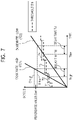
- FIG. 7 shows an embodiment disclosed herein, and is a diagram showing an example of a threshold Dth of a dose (accumulated dose) set in the imaging control unit 133 and a relationship between a change of the threshold Dth with a time and a dose (accumulated dose) D.
- FIG. 7 shows the relationship between the dose (accumulated dose) D shown on the vertical axis and the time (elapsed time) shown on the horizontal axis.
- the imaging control unit 133 performs a control to change the threshold Dth of the dose (accumulated dose) in accordance with a elapsed time from a start of irradiation of the radiation R. Specifically, in FIG. 7 , the imaging control unit 133 performs the control to increase the threshold Dth of the dose (accumulated dose) with the elapsed time.
- the imaging control unit 133 When the dose (accumulated dose) D obtained from the arithmetic unit 132 is equal to or larger than the threshold Dth of the dose (accumulated dose) which changes in accordance with the elapsed time as shown in FIG. 7 (step S604/NO), the imaging control unit 133 outputs the irradiation stop signal to the radiation generator 110 in step S605 of FIG. 2 . At this time, the radiation R is continuously irradiated by a period of the delay time Td from the output of the irradiation stop signal from the imaging control unit 133 to the radiation generator 110 until the irradiation of the radiation R is actually stopped in the radiation generator 110.
- the dose (accumulated dose) D obtained from the arithmetic unit 132 in the irradiation time Thigh is equal to or larger than the threshold Dth of the dose (accumulated dose).
- the imaging control unit 133 outputs the irradiation stop signal to the radiation generator 110, and thereafter, the irradiation of the radiation R from the radiation generator 110 is stopped. In this case, the radiation R of the dose (accumulated dose) Dhigh reaches the radiation imaging device 120.
- the dose (accumulated dose) D obtained from the arithmetic unit 132 in the irradiation time Tlow is equal to or greater than the threshold Dth of the dose (accumulated dose).
- the imaging control unit 133 outputs the irradiation stop signal to the radiation generator 110, and thereafter, the irradiation of the radiation R from the radiation generator 110 is stopped. In this case, the radiation R of the dose (accumulated dose) Dlow reaches the radiation imaging device 120.
- the dose rate 701 and the dose rate 702 of the radiation R are determined based on the relationship between the dose (accumulated dose) D and the time.
- the threshold Dth of the dose (accumulated dose) is made constant, the actual dose (accumulated dose) D changes in accordance with the change in the dose rate, and becomes a value away from the reference value Dref of the dose (accumulated dose).
- Dref the reference value
- both the dose (accumulated dose) Dhigh of the high dose rate 701 and the dose (accumulated dose) Dlow of the low dose rate 702 can be set to a value close to the reference value Dref of the dose (accumulated dose).
- the irradiation stop control of the radiation R can be performed with high accuracy regardless of the dose rate.
- the change of the threshold Dth of the dose (accumulated dose) with the time can be expressed by a step function that changes stepwisely with respect to the elapsed time.
- the length of the time segments T1 to T4 of the step function relating to the threshold Dth of the dose (accumulated dose) may be different for each of the time segments as shown in FIG. 3 .
- the lengths of the time segments T1 to T4 of the step function is gradually increased with the elapsed time (make T2 longer than T1, T3 longer than T2, T4 longer than T3), the number of time segments can be reduced.
- the imaging control unit 133 decreases an increment amount per time of the threshold Dth of the dose (accumulated dose) with the elapsed time. If the number of time segments can be reduced, the memory to be used is reduced, and the load on the control unit 130 by changing the threshold Dth of the dose (accumulated dose) can be reduced.
- the change of the threshold Dth of the dose (accumulated dose) with the time may be continuously changed with respect to the elapsed time.
- the threshold Dth of the dose (accumulated dose) with respect to the elapsed time t can be set to satisfy the following mathematic (1) by using the elapsed time t, the delay time Td, and the reference value Dref of the dose (accumulated dose).
- Dth t t / t + Td Dref
- the imaging control unit 133 changes the threshold Dth of the dose (accumulated dose) in accordance with the elapsed time t, and sets the change of the threshold Dth of the dose (accumulated dose) with the time based the reference value Dref of the dose (accumulated dose) and the delay time Td.
- the imaging control unit 133 changes the threshold Dth of the dose (accumulated dose) in accordance with the elapsed time t, and sets the change of the threshold Dth of the dose (accumulated dose) with the time based on the reference value Dref of the dose (accumulated dose) and the delay time Td.
- the irradiation stop control of the radiation from the radiation generator 110 can be performed with high accuracy. That is, the AEC can be performed with high accuracy.
- the irradiation stop control of the radiation from the radiation generator can be performed with high accuracy.
- the disclosure of this specification can also be realized by providing a program that implements one or more functions of the above embodiments to a system or device via a network or storage medium, with one or more processors in the computer of the system or device reading and executing the program. It can also be realized by a circuit (for example, ASIC) which realizes one or more functions.
- This program and a computer readable storage medium storing the program are included in the disclosure herein.
- the processor or circuit can also include a central processing unit (CPU), a microprocessing unit (MPU), a graphics processing unit (GPU), an application specific integrated circuit (ASIC), or a field programmable gateway (FPGA).
- the processor or circuit may also include a digital signal processor (DSP), a data flow processor (DFP), or a neural processing unit (NPU).
- DSP digital signal processor
- DFP data flow processor
- NPU neural processing unit
Landscapes
- Health & Medical Sciences (AREA)
- Life Sciences & Earth Sciences (AREA)
- Medical Informatics (AREA)
- Engineering & Computer Science (AREA)
- Radiology & Medical Imaging (AREA)
- Biomedical Technology (AREA)
- Biophysics (AREA)
- Nuclear Medicine, Radiotherapy & Molecular Imaging (AREA)
- Optics & Photonics (AREA)
- Pathology (AREA)
- Physics & Mathematics (AREA)
- High Energy & Nuclear Physics (AREA)
- Heart & Thoracic Surgery (AREA)
- Molecular Biology (AREA)
- Surgery (AREA)
- Animal Behavior & Ethology (AREA)
- General Health & Medical Sciences (AREA)
- Public Health (AREA)
- Veterinary Medicine (AREA)
- Apparatus For Radiation Diagnosis (AREA)
Applications Claiming Priority (3)
| Application Number | Priority Date | Filing Date | Title |
|---|---|---|---|
| JP2020036975A JP7467164B2 (ja) | 2020-03-04 | 2020-03-04 | 放射線撮影装置、放射線撮影システム、制御装置及び照射停止方法 |
| JP2020036784A JP2021137255A (ja) | 2020-03-04 | 2020-03-04 | 放射線撮影システム及びその制御方法 |
| PCT/JP2021/007706 WO2021177229A1 (fr) | 2020-03-04 | 2021-03-01 | Système radiographique, dispositif de commande et procédé de commande de système radiographique |
Publications (2)
| Publication Number | Publication Date |
|---|---|
| EP4094691A1 true EP4094691A1 (fr) | 2022-11-30 |
| EP4094691A4 EP4094691A4 (fr) | 2024-02-28 |
Family
ID=77613461
Family Applications (1)
| Application Number | Title | Priority Date | Filing Date |
|---|---|---|---|
| EP21764403.8A Pending EP4094691A4 (fr) | 2020-03-04 | 2021-03-01 | Système radiographique, dispositif de commande et procédé de commande de système radiographique |
Country Status (3)
| Country | Link |
|---|---|
| US (2) | US12295779B2 (fr) |
| EP (1) | EP4094691A4 (fr) |
| WO (1) | WO2021177229A1 (fr) |
Families Citing this family (7)
| Publication number | Priority date | Publication date | Assignee | Title |
|---|---|---|---|---|
| JP7619821B2 (ja) | 2021-02-09 | 2025-01-22 | キヤノン株式会社 | 情報処理装置、放射線撮影システム、情報処理方法およびプログラム |
| JP7441203B2 (ja) * | 2021-10-21 | 2024-02-29 | キヤノン株式会社 | 放射線撮像システム、放射線制御装置、放射線撮像システムの制御方法、放射線制御装置の制御方法、プログラム、および、記憶媒体 |
| JP2023111636A (ja) * | 2022-01-31 | 2023-08-10 | キヤノン株式会社 | 放射線撮像装置および放射線撮像システム |
| US12339408B2 (en) | 2022-02-16 | 2025-06-24 | Canon Kabushiki Kaisha | Radiation imaging apparatus and radiation imaging system |
| JP2023159686A (ja) * | 2022-04-20 | 2023-11-01 | キヤノン株式会社 | 放射線撮像装置、放射線撮像システム、および放射線撮像装置の制御方法 |
| US20240138799A1 (en) * | 2022-11-02 | 2024-05-02 | Canon Kabushiki Kaisha | Radiographic imaging apparatus, radiographic imaging system, and method for controlling radiographic imaging apparatus |
| CN117214207B (zh) * | 2023-08-11 | 2024-11-15 | 脉冲视觉(北京)科技有限公司 | 获取射线透过待测对象后信号强度的方法、系统和设备 |
Family Cites Families (9)
| Publication number | Priority date | Publication date | Assignee | Title |
|---|---|---|---|---|
| DE3402888A1 (de) | 1984-01-27 | 1985-08-01 | Siemens AG, 1000 Berlin und 8000 München | Roentgendiagnostikanlage |
| US8992413B2 (en) | 2011-05-31 | 2015-03-31 | Covidien Lp | Modified wet tip antenna design |
| JP5460674B2 (ja) * | 2011-11-15 | 2014-04-02 | 富士フイルム株式会社 | 放射線撮影装置およびその制御方法、並びに放射線撮影システム |
| JP5558538B2 (ja) | 2011-12-08 | 2014-07-23 | 富士フイルム株式会社 | 放射線撮影装置、放射線撮影システム、放射線撮影装置の制御方法及び制御プログラム |
| JP6056380B2 (ja) | 2012-10-31 | 2017-01-11 | コニカミノルタ株式会社 | 放射線画像撮影システム |
| JP6552306B2 (ja) * | 2015-07-09 | 2019-07-31 | キヤノン株式会社 | 放射線撮像装置、放射線撮像システム、及び、放射線撮像装置による方法 |
| JP6745644B2 (ja) * | 2016-05-24 | 2020-08-26 | キヤノン株式会社 | 制御装置、その動作方法およびプログラム |
| JP2020036784A (ja) | 2018-09-05 | 2020-03-12 | 国立大学法人 岡山大学 | 人工血管 |
| JP7467164B2 (ja) | 2020-03-04 | 2024-04-15 | キヤノン株式会社 | 放射線撮影装置、放射線撮影システム、制御装置及び照射停止方法 |
-
2021
- 2021-03-01 EP EP21764403.8A patent/EP4094691A4/fr active Pending
- 2021-03-01 WO PCT/JP2021/007706 patent/WO2021177229A1/fr not_active Ceased
-
2022
- 2022-08-24 US US17/894,231 patent/US12295779B2/en active Active
-
2025
- 2025-04-09 US US19/174,452 patent/US20250235177A1/en active Pending
Also Published As
| Publication number | Publication date |
|---|---|
| US12295779B2 (en) | 2025-05-13 |
| WO2021177229A1 (fr) | 2021-09-10 |
| EP4094691A4 (fr) | 2024-02-28 |
| US20250235177A1 (en) | 2025-07-24 |
| US20220401054A1 (en) | 2022-12-22 |
Similar Documents
| Publication | Publication Date | Title |
|---|---|---|
| EP4094691A1 (fr) | Système radiographique, dispositif de commande et procédé de commande de système radiographique | |
| CN105433967B (zh) | 放射线图像分析装置及方法以及程序 | |
| JP7567082B2 (ja) | 放射線撮影装置、放射線撮影システム、制御装置及び照射停止方法 | |
| EP1388741B1 (fr) | Dosimétrie de la zone exposée et dosimétrie de la zone absorbée | |
| US8503607B2 (en) | X-ray imaging apparatus and control method therefor | |
| JP6156847B2 (ja) | 放射線画像処理装置および方法並びにプログラム | |
| EP3804623A1 (fr) | Dispositif de radiographie, procédé de radiographie et programme | |
| EP3403585B1 (fr) | Appareil de radiographie, système de radiographie et procédé de gestion d'indice de dosage | |
| EP3301650B1 (fr) | Appareil, procédé et système de traitement d'image et programme | |
| JP6745644B2 (ja) | 制御装置、その動作方法およびプログラム | |
| JP5388476B2 (ja) | 画像表示装置、乳房x線撮影装置および画像表示プログラム | |
| EP3884867A1 (fr) | Dispositif de traitement d'image, procédé de traitement d'image, dispositif de traitement d'informations médicales, procédé de traitement d'informations médicales, système d'imagerie par rayonnement, et programme | |
| US20240020849A1 (en) | Radiation image processing apparatus, operation method of radiation image processing apparatus, and non-transitory computer readable medium | |
| EP4176813B1 (fr) | Appareil d'imagerie par rayonnement, système d'imagerie par rayonnement et procédé de commande | |
| JP2021137255A (ja) | 放射線撮影システム及びその制御方法 | |
| JP2019084158A (ja) | 画像処理装置、画像処理方法、放射線撮影装置、放射線撮影装置の制御方法、およびプログラム | |
| US20170020476A1 (en) | Method for generating approximate function of total mtf of x-ray image, based on conditions for imaging with x-ray | |
| JP7192921B2 (ja) | 放射線画像処理装置、散乱線補正方法及びプログラム | |
| JP2010240054A (ja) | X線診断装置及び画像処理装置 | |
| EP4616810A1 (fr) | Dispositif de traitement d'image de rayonnement, procédé de traitement d'image de rayonnement et programme de traitement d'image de rayonnement | |
| JP2015093013A (ja) | 放射線画像処理装置、放射線撮影装置、それらの制御方法及びプログラム | |
| JP2019208927A (ja) | 画像処理装置、画像処理方法及びプログラム | |
| JP2023070098A (ja) | 放射線撮影装置、放射線撮影システム、及び制御方法 | |
| JP2021058418A (ja) | 画像処理装置および画像処理方法、放射線撮影装置、プログラム | |
| JP2023078875A (ja) | 放射線撮像装置、放射線撮像システム及び放射線撮像装置の制御方法 |
Legal Events
| Date | Code | Title | Description |
|---|---|---|---|
| STAA | Information on the status of an ep patent application or granted ep patent |
Free format text: STATUS: THE INTERNATIONAL PUBLICATION HAS BEEN MADE |
|
| PUAI | Public reference made under article 153(3) epc to a published international application that has entered the european phase |
Free format text: ORIGINAL CODE: 0009012 |
|
| STAA | Information on the status of an ep patent application or granted ep patent |
Free format text: STATUS: REQUEST FOR EXAMINATION WAS MADE |
|
| 17P | Request for examination filed |
Effective date: 20220825 |
|
| AK | Designated contracting states |
Kind code of ref document: A1 Designated state(s): AL AT BE BG CH CY CZ DE DK EE ES FI FR GB GR HR HU IE IS IT LI LT LU LV MC MK MT NL NO PL PT RO RS SE SI SK SM TR |
|
| DAV | Request for validation of the european patent (deleted) | ||
| DAX | Request for extension of the european patent (deleted) | ||
| A4 | Supplementary search report drawn up and despatched |
Effective date: 20240130 |
|
| RIC1 | Information provided on ipc code assigned before grant |
Ipc: A61B 6/00 20060101AFI20240124BHEP |
|
| STAA | Information on the status of an ep patent application or granted ep patent |
Free format text: STATUS: EXAMINATION IS IN PROGRESS |
|
| 17Q | First examination report despatched |
Effective date: 20250327 |