EP4094885A1 - Dispositif combiné de transfert et de stockage, ainsi qu'installation d'usinage par enlèvement des copeaux - Google Patents
Dispositif combiné de transfert et de stockage, ainsi qu'installation d'usinage par enlèvement des copeaux Download PDFInfo
- Publication number
- EP4094885A1 EP4094885A1 EP22174063.2A EP22174063A EP4094885A1 EP 4094885 A1 EP4094885 A1 EP 4094885A1 EP 22174063 A EP22174063 A EP 22174063A EP 4094885 A1 EP4094885 A1 EP 4094885A1
- Authority
- EP
- European Patent Office
- Prior art keywords
- handling
- workpiece
- interface
- transfer
- machine tool
- Prior art date
- Legal status (The legal status is an assumption and is not a legal conclusion. Google has not performed a legal analysis and makes no representation as to the accuracy of the status listed.)
- Pending
Links
Images




Classifications
-
- B—PERFORMING OPERATIONS; TRANSPORTING
- B23—MACHINE TOOLS; METAL-WORKING NOT OTHERWISE PROVIDED FOR
- B23Q—DETAILS, COMPONENTS, OR ACCESSORIES FOR MACHINE TOOLS, e.g. ARRANGEMENTS FOR COPYING OR CONTROLLING; MACHINE TOOLS IN GENERAL CHARACTERISED BY THE CONSTRUCTION OF PARTICULAR DETAILS OR COMPONENTS; COMBINATIONS OR ASSOCIATIONS OF METAL-WORKING MACHINES, NOT DIRECTED TO A PARTICULAR RESULT
- B23Q7/00—Arrangements for handling work specially combined with or arranged in, or specially adapted for use in connection with, machine tools, e.g. for conveying, loading, positioning, discharging, sorting
-
- B—PERFORMING OPERATIONS; TRANSPORTING
- B23—MACHINE TOOLS; METAL-WORKING NOT OTHERWISE PROVIDED FOR
- B23Q—DETAILS, COMPONENTS, OR ACCESSORIES FOR MACHINE TOOLS, e.g. ARRANGEMENTS FOR COPYING OR CONTROLLING; MACHINE TOOLS IN GENERAL CHARACTERISED BY THE CONSTRUCTION OF PARTICULAR DETAILS OR COMPONENTS; COMBINATIONS OR ASSOCIATIONS OF METAL-WORKING MACHINES, NOT DIRECTED TO A PARTICULAR RESULT
- B23Q7/00—Arrangements for handling work specially combined with or arranged in, or specially adapted for use in connection with, machine tools, e.g. for conveying, loading, positioning, discharging, sorting
- B23Q7/10—Arrangements for handling work specially combined with or arranged in, or specially adapted for use in connection with, machine tools, e.g. for conveying, loading, positioning, discharging, sorting by means of magazines
-
- B—PERFORMING OPERATIONS; TRANSPORTING
- B23—MACHINE TOOLS; METAL-WORKING NOT OTHERWISE PROVIDED FOR
- B23Q—DETAILS, COMPONENTS, OR ACCESSORIES FOR MACHINE TOOLS, e.g. ARRANGEMENTS FOR COPYING OR CONTROLLING; MACHINE TOOLS IN GENERAL CHARACTERISED BY THE CONSTRUCTION OF PARTICULAR DETAILS OR COMPONENTS; COMBINATIONS OR ASSOCIATIONS OF METAL-WORKING MACHINES, NOT DIRECTED TO A PARTICULAR RESULT
- B23Q7/00—Arrangements for handling work specially combined with or arranged in, or specially adapted for use in connection with, machine tools, e.g. for conveying, loading, positioning, discharging, sorting
- B23Q7/04—Arrangements for handling work specially combined with or arranged in, or specially adapted for use in connection with, machine tools, e.g. for conveying, loading, positioning, discharging, sorting by means of grippers
- B23Q7/046—Handling workpieces or tools
-
- B—PERFORMING OPERATIONS; TRANSPORTING
- B23—MACHINE TOOLS; METAL-WORKING NOT OTHERWISE PROVIDED FOR
- B23Q—DETAILS, COMPONENTS, OR ACCESSORIES FOR MACHINE TOOLS, e.g. ARRANGEMENTS FOR COPYING OR CONTROLLING; MACHINE TOOLS IN GENERAL CHARACTERISED BY THE CONSTRUCTION OF PARTICULAR DETAILS OR COMPONENTS; COMBINATIONS OR ASSOCIATIONS OF METAL-WORKING MACHINES, NOT DIRECTED TO A PARTICULAR RESULT
- B23Q1/00—Members which are comprised in the general build-up of a form of machine, particularly relatively large fixed members
- B23Q1/01—Frames, beds, pillars or like members; Arrangement of ways
- B23Q1/015—Frames, beds, pillars
-
- B—PERFORMING OPERATIONS; TRANSPORTING
- B23—MACHINE TOOLS; METAL-WORKING NOT OTHERWISE PROVIDED FOR
- B23Q—DETAILS, COMPONENTS, OR ACCESSORIES FOR MACHINE TOOLS, e.g. ARRANGEMENTS FOR COPYING OR CONTROLLING; MACHINE TOOLS IN GENERAL CHARACTERISED BY THE CONSTRUCTION OF PARTICULAR DETAILS OR COMPONENTS; COMBINATIONS OR ASSOCIATIONS OF METAL-WORKING MACHINES, NOT DIRECTED TO A PARTICULAR RESULT
- B23Q1/00—Members which are comprised in the general build-up of a form of machine, particularly relatively large fixed members
- B23Q1/25—Movable or adjustable work or tool supports
- B23Q1/44—Movable or adjustable work or tool supports using particular mechanisms
- B23Q1/48—Movable or adjustable work or tool supports using particular mechanisms with sliding pairs and rotating pairs
- B23Q1/4876—Movable or adjustable work or tool supports using particular mechanisms with sliding pairs and rotating pairs a single sliding pair followed parallelly by a single rotating pair
- B23Q1/488—Movable or adjustable work or tool supports using particular mechanisms with sliding pairs and rotating pairs a single sliding pair followed parallelly by a single rotating pair followed perpendicularly by a single rotating pair
-
- B—PERFORMING OPERATIONS; TRANSPORTING
- B23—MACHINE TOOLS; METAL-WORKING NOT OTHERWISE PROVIDED FOR
- B23Q—DETAILS, COMPONENTS, OR ACCESSORIES FOR MACHINE TOOLS, e.g. ARRANGEMENTS FOR COPYING OR CONTROLLING; MACHINE TOOLS IN GENERAL CHARACTERISED BY THE CONSTRUCTION OF PARTICULAR DETAILS OR COMPONENTS; COMBINATIONS OR ASSOCIATIONS OF METAL-WORKING MACHINES, NOT DIRECTED TO A PARTICULAR RESULT
- B23Q3/00—Devices holding, supporting, or positioning work or tools, of a kind normally removable from the machine
- B23Q3/155—Arrangements for automatic insertion or removal of tools, e.g. combined with manual handling
- B23Q3/1552—Arrangements for automatic insertion or removal of tools, e.g. combined with manual handling parts of devices for automatically inserting or removing tools
- B23Q3/1554—Transfer mechanisms, e.g. tool gripping arms; Drive mechanisms therefore
-
- B—PERFORMING OPERATIONS; TRANSPORTING
- B23—MACHINE TOOLS; METAL-WORKING NOT OTHERWISE PROVIDED FOR
- B23Q—DETAILS, COMPONENTS, OR ACCESSORIES FOR MACHINE TOOLS, e.g. ARRANGEMENTS FOR COPYING OR CONTROLLING; MACHINE TOOLS IN GENERAL CHARACTERISED BY THE CONSTRUCTION OF PARTICULAR DETAILS OR COMPONENTS; COMBINATIONS OR ASSOCIATIONS OF METAL-WORKING MACHINES, NOT DIRECTED TO A PARTICULAR RESULT
- B23Q37/00—Metal-working machines, or constructional combinations thereof, built-up from units designed so that at least some of the units can form parts of different machines or combinations; Units therefor in so far as the feature of interchangeability is important
-
- B—PERFORMING OPERATIONS; TRANSPORTING
- B23—MACHINE TOOLS; METAL-WORKING NOT OTHERWISE PROVIDED FOR
- B23Q—DETAILS, COMPONENTS, OR ACCESSORIES FOR MACHINE TOOLS, e.g. ARRANGEMENTS FOR COPYING OR CONTROLLING; MACHINE TOOLS IN GENERAL CHARACTERISED BY THE CONSTRUCTION OF PARTICULAR DETAILS OR COMPONENTS; COMBINATIONS OR ASSOCIATIONS OF METAL-WORKING MACHINES, NOT DIRECTED TO A PARTICULAR RESULT
- B23Q7/00—Arrangements for handling work specially combined with or arranged in, or specially adapted for use in connection with, machine tools, e.g. for conveying, loading, positioning, discharging, sorting
- B23Q7/04—Arrangements for handling work specially combined with or arranged in, or specially adapted for use in connection with, machine tools, e.g. for conveying, loading, positioning, discharging, sorting by means of grippers
-
- B—PERFORMING OPERATIONS; TRANSPORTING
- B23—MACHINE TOOLS; METAL-WORKING NOT OTHERWISE PROVIDED FOR
- B23Q—DETAILS, COMPONENTS, OR ACCESSORIES FOR MACHINE TOOLS, e.g. ARRANGEMENTS FOR COPYING OR CONTROLLING; MACHINE TOOLS IN GENERAL CHARACTERISED BY THE CONSTRUCTION OF PARTICULAR DETAILS OR COMPONENTS; COMBINATIONS OR ASSOCIATIONS OF METAL-WORKING MACHINES, NOT DIRECTED TO A PARTICULAR RESULT
- B23Q7/00—Arrangements for handling work specially combined with or arranged in, or specially adapted for use in connection with, machine tools, e.g. for conveying, loading, positioning, discharging, sorting
- B23Q7/04—Arrangements for handling work specially combined with or arranged in, or specially adapted for use in connection with, machine tools, e.g. for conveying, loading, positioning, discharging, sorting by means of grippers
- B23Q7/047—Arrangements for handling work specially combined with or arranged in, or specially adapted for use in connection with, machine tools, e.g. for conveying, loading, positioning, discharging, sorting by means of grippers the gripper supporting the workpiece during machining
-
- B—PERFORMING OPERATIONS; TRANSPORTING
- B23—MACHINE TOOLS; METAL-WORKING NOT OTHERWISE PROVIDED FOR
- B23Q—DETAILS, COMPONENTS, OR ACCESSORIES FOR MACHINE TOOLS, e.g. ARRANGEMENTS FOR COPYING OR CONTROLLING; MACHINE TOOLS IN GENERAL CHARACTERISED BY THE CONSTRUCTION OF PARTICULAR DETAILS OR COMPONENTS; COMBINATIONS OR ASSOCIATIONS OF METAL-WORKING MACHINES, NOT DIRECTED TO A PARTICULAR RESULT
- B23Q7/00—Arrangements for handling work specially combined with or arranged in, or specially adapted for use in connection with, machine tools, e.g. for conveying, loading, positioning, discharging, sorting
- B23Q7/14—Arrangements for handling work specially combined with or arranged in, or specially adapted for use in connection with, machine tools, e.g. for conveying, loading, positioning, discharging, sorting co-ordinated in production lines
-
- B—PERFORMING OPERATIONS; TRANSPORTING
- B23—MACHINE TOOLS; METAL-WORKING NOT OTHERWISE PROVIDED FOR
- B23Q—DETAILS, COMPONENTS, OR ACCESSORIES FOR MACHINE TOOLS, e.g. ARRANGEMENTS FOR COPYING OR CONTROLLING; MACHINE TOOLS IN GENERAL CHARACTERISED BY THE CONSTRUCTION OF PARTICULAR DETAILS OR COMPONENTS; COMBINATIONS OR ASSOCIATIONS OF METAL-WORKING MACHINES, NOT DIRECTED TO A PARTICULAR RESULT
- B23Q3/00—Devices holding, supporting, or positioning work or tools, of a kind normally removable from the machine
- B23Q3/155—Arrangements for automatic insertion or removal of tools, e.g. combined with manual handling
- B23Q3/1552—Arrangements for automatic insertion or removal of tools, e.g. combined with manual handling parts of devices for automatically inserting or removing tools
- B23Q3/1554—Transfer mechanisms, e.g. tool gripping arms; Drive mechanisms therefore
- B23Q2003/155404—Transfer mechanisms, e.g. tool gripping arms; Drive mechanisms therefore the transfer mechanism comprising a single gripper
- B23Q2003/155407—Transfer mechanisms, e.g. tool gripping arms; Drive mechanisms therefore the transfer mechanism comprising a single gripper linearly movable
Definitions
- the present disclosure generally deals with precision mechanical production using machine tools.
- the present disclosure relates, in accordance with certain aspects, to a manufacturing system for machining.
- the present disclosure relates to a combined transfer and storage device for machining.
- the present disclosure relates to a system for machining, which has a combined transfer and storage device and a manufacturing system.
- the present disclosure relates to machine tools with a compact design and their integration into manufacturing systems and systems for machining.
- Machine tools with a compact design are, for example, those with a working area that is smaller than 250 mm ⁇ 250 mm ⁇ 250 mm.
- the working space of the machine tool is smaller than 200 mm ⁇ 200 mm ⁇ 200 mm. In exemplary configurations, the working space of the machine tool is smaller than 150 mm ⁇ 150 mm ⁇ 150 mm. In exemplary configurations, the working space of the machine tool is smaller than 100 mm ⁇ 100 mm ⁇ 100 mm. In exemplary configurations, the working space of the machine tool is smaller than 75 mm ⁇ 75 mm ⁇ 75 mm.
- This information relates in particular to the possible feeds (traverse paths) along the X, Y and Z axes.
- the working space can be designed in the form of a cube. However, cuboid installation spaces are also conceivable, the travel paths of which in X, Y and Z are not uniform.
- machine tools designed in this way are suitable for precision machining, for example in the context of the manufacture of watches, jewelery and the like. It goes without saying that other applications are also conceivable.
- the workpieces are blanks for watches and similar fine mechanical products. Examples are watch plates, base plates, gears, dials, bridges, cocks, covers and housing parts for watches and comparable flat parts.
- Machine tools and systems for machining are known. From the U.S. 2019/0084102 A1 a production plant is known which has a plurality of compactly designed machine tools arranged one above the other and next to one another, which are arranged in a common housing, with a robot for changing tools and/or workpieces being additionally provided, which is arranged so that it can be moved horizontally on a vertically moveable beam.
- a mobile robot cell with a housing is known, which can be placed in front of an opening to a working space of a processing machine, if required, in order to be able to load workpieces with a robot.
- a processing system for workpieces is known, with at least one processing machine, with a protective housing having at least one shelf magazine and with a loading device arranged inside the protective housing for loading and unloading the processing machine, the loading device comprising a carriage with an adjustable boom that can be moved along a guide, which carries at least one handling unit for parts to be handled, wherein the guide for the carriage is provided in an overhead area, and wherein the arm of the loading device articulated on the underside of the carriage has two arms coupled to one another, which can be pivoted relative to one another.
- a manufacturing system for the flexible manufacture of workpieces which has several machine tools, a transport system for workpieces connecting the machine tools, and a loading device for each machine tool, which is arranged between the machine tool and the transport system and is designed for loading and unloading the machine tool.
- an arrangement which comprises a single-station metal cutting machine and a robot cell, the robot cell being able to be coupled to the metal cutting machine for loading and unloading the latter, the metal cutting machine having a machine room and the robot cell having a robot cell room, and the machine room being the machine room in the coupled state of the robot cell and the robot cell space form a common processing space.
- the automation technology for example robots with grippers and the like
- the machine tool in the installation space (possibly work space) of the machine tool in order to enable workpieces and tools to be handed over.
- the present disclosure is based on the task of providing solutions for processing, in particular precision machining, using compactly designed Specify machine tools.
- this relates to the automation of the processing, for example to handling cells and the like, in order to take into account the special conditions in the case of compact machine tools.
- production systems should be able to be implemented that enable partially automated or even highly automated production even with only small installation spaces. This refers, for example, to the workpiece change.
- this relates to the tool change.
- a combined transfer and storage device is to be specified within the scope of the present disclosure, which can be combined with at least one manufacturing system comprising a machine tool. In this way, an efficient and at least partially autonomous production of medium and large series should be made possible.
- a manufacturing system is to be specified which advantageously links a manufacturing system provided with a handling cell to a combined transfer and storage device.
- Approaches for linking and automating compact machine tools are also to be described within the scope of the present disclosure.
- the machine tool can be operated at least partially automatically. This includes, for example, that workpieces can be changed semi-automatically or fully automatically.
- the handling cell is adjacent to the working area of the machine tool, for example arranged at a small distance to the side therefrom.
- the handling unit is assigned to the handling cell and not to the machine tool. This means that in the case of the machine tool, which only has a relatively small working area, no complex interventions and adjustments are required.
- the front side of the working space is therefore free, at least in exemplary configurations, and can be viewed and accessed by an operator.
- the front can also be referred to as the operator side.
- the front is arranged opposite the back. Lateral sides of the work area are available for handling (workpiece change, tool change). In this way, the compact design is taken into account.
- the handling unit can approach the workpiece holder and a pallet that may already be arranged there, in order to carry out a workpiece change (loading and unloading) there. This can also affect the removal of remnants (waste).
- the tool holder is designed as a tool spindle and is provided with a vertically oriented axis.
- the workpiece holder is assigned, for example, to a swivel axis or a swivel table of the machine tool.
- the first interface can also be referred to as a charging interface.
- the second interface can also be referred to as a transfer interface.
- the handling cell and consequently the production system can be coupled to a transfer device or a combined transfer and storage device via the second interface.
- the handling unit can work together with other handling technology/transfer technology in order to feed workpieces to or remove workpieces from the buffer store of the handling cell. This happens, for example, in blocks in trays or the like.
- the handling cell can serve as a lock between the machine tool (or its work area) and a transfer system.
- the basic structure of the machine tool in particular the mechanical basic structure, remains largely or completely unaffected when the machine tool is coupled to the handling cell. This allows the machine tool to be used in plants and systems with different degrees of automation.
- the handling cell can also be referred to as a handling module.
- the working space of the machine is primarily, at least predominantly, possibly even exclusively, available for machining.
- the working space is not claimed by handling technology and the like, at least during the machining. This also takes account of the cramped installation space.
- the handling unit provides a primary function and at least one secondary function, the primary function including a workpiece change and the secondary function including a tool change.
- the handling cell can also be used for changing tools, at least in exemplary configurations.
- this is only a secondary function, that is to say a function that is subordinate to the workpiece change. Nevertheless, the provision of a primary function and a secondary function expands the range of applications of the handling cell.
- the handling unit is designed as an articulated arm robot, in particular as a hanging articulated arm robot, whose range of motion includes the first interface, a workpiece transfer position with the workpiece holder and preferably the second interface.
- the handling unit can be designed as an industrial robot, for example as an industrial robot arranged in a suspended manner.
- the handling unit is arranged in a suspended manner. In this way, the floor area of the handling cell can be used for other purposes.
- the handling unit has a double gripper which is used at least for gripping is formed from blanks.
- a double gripper which is used at least for gripping is formed from blanks.
- the machine tool is arranged, for example, in a machining cell that is adjacent to the handling cell.
- the handling unit overlaps the working space of the machine tool with its range of movement, at least in sections, so that a loading process and optionally also an unloading process is possible.
- blanks can be transferred to the workpiece holder. This can include transferring the blanks to a pallet or clamping device which is arranged on the workpiece holder or is designed as part of the workpiece holder.
- the double gripper is also designed to grip machined parts.
- this includes workpieces that are separated from a surrounding remainder of the blank.
- this includes machined workpieces that are still connected to the remainder of the blank.
- the double gripper is designed to grip remnants that result after the workpiece has been separated from the blank.
- Such remnants are referred to as slugs, for example.
- the workpieces are, for example, shaped like circular blanks, discs, oval or square and are produced as a section from the blank, with a residual piece possibly remaining.
- the handling unit can accept and remove workpieces without a remainder, workpieces that are still connected to the remainder, or remainders that have been separated from the workpiece. If a double gripper is provided, a new blank can be placed on the workpiece holder without much delay.
- the buffer store comprises at least one support for a workpiece carrier with a plurality of storage locations which are designed at least to accommodate blanks.
- the workpiece carrier is designed, for example, as a tray or workpiece pallet for receiving a plurality of workpieces or blanks.
- the workpiece carrier is also designed to accommodate machined workpieces or offcuts.
- the workpiece carrier can also be designed and described as a tray.
- the workpiece carrier can be provided via the second interface. This can be done using a transfer system, for example. However, manual loading is also conceivable, possibly with machine support.
- workpiece carriers which can accommodate a plurality or multitude of workpieces (or blanks and/or remnants)
- the comparatively filigree workpieces can be handled and transferred efficiently.
- the transfer can take place, for example, between a storage level of a combined transfer and storage device and the machine tool, with the transfer taking place through the handling cell. This allows efficient transfer of a large number of parts held by the workpiece carrier. If this (global) transfer takes place using workpiece carriers, the individual workpieces can be moved quickly and safely. Furthermore, storage or temporary storage is simplified; if required, this can also be done directly in the (transportable) workpiece carrier.
- the handling cell allows the workpieces to be separated. This (local) transfer can take place taking into account the accuracy requirements and the possible fragility of the workpieces.
- the handling cell can also have a reference part, which has a defined stop for a blank of the workpiece, for example. This allows the workpiece on Reference part are specifically aligned. In this way, the demands on the accuracy of the alignment of the workpieces in the workpiece carrier are reduced.
- At least a first workpiece carrier for preparing blanks and a second workpiece carrier for receiving machined workpieces or offcuts are provided, which can be received together in the handling cell.
- the handling cell itself can provide a buffer memory.
- the handling cell can be operated autonomously or semi-autonomously, at least for a certain number of workpieces, without requiring an additional transfer via the transfer interface.
- the workpiece carriers are arranged in the handling cell in the area of movement of the handling unit.
- the handling cell can have appropriate supports for the workpiece carriers.
- the manufacturing system also has at least one auxiliary memory, which is designed in particular for storing random samples.
- the auxiliary storage can also be designed as a quarantine storage.
- the auxiliary memory can be used to temporarily store workpieces for which measurements or similar quality monitoring measures are provided.
- the auxiliary memory can also be used as a buffer for potentially bad parts, which may be released as good parts after testing. The temporarily stored parts can be handled within the handling cell.
- the handling unit has a suction gripper, which is designed in particular to pick up machined workpieces.
- the handling unit is designed to switch between a mechanical gripper (with gripper fingers or clamps) and a suction gripper (fluidic gripper).
- a mechanical gripper with gripper fingers or clamps
- a suction gripper fluididic gripper
- a suction pad allows the handling of fragile workpieces. In this way, for example, workpieces that have been completely separated from the remainder of the blank can be gently removed from the work area.
- the handling cell also has a monitoring station, for example an optical monitoring station.
- a monitoring station for example an optical monitoring station.
- production-related monitoring can take place.
- a monitoring station in the handling cell can be combined with an auxiliary store in the handling cell.
- the manufacturing system also has at least one reference part for aligning workpieces, in particular for centering. In this way, for example, the blanks can be centered. This allows the use of loading aids with reduced positioning accuracy requirements.
- the handling unit can, for example, first grab a blank from the workpiece carrier (for example tray) and then place it on the reference part in order to align the blank and, if necessary, to center it. In this way, positioning errors when loading and unloading the machine tool can be reduced.
- the workpiece carrier for example tray
- At least the first interface between the machine tool and the handling cell can be closed with a door, in particular with a sliding door.
- the door is designed in the manner of a guillotine, i.e. as a vertically movable sliding door.
- Other locking devices are conceivable.
- the door allows a hermetic separation between the work area and the handling cell during processing. This is also possible because the handling unit of the handling cell does not take up the work space of the machine tool during machining, but is only brought in as required for changing the workpiece. In an exemplary embodiment, the handling unit of the handling cell is moved completely out of the processing cell during processing.
- the design as a vertically movable door allows access to the respective front sides (operator side) of the handling cell and the processing cell. For example, when the door is open, it can move into an area (above or below the interface) that is not otherwise used and does not obstruct the operator's clear view.
- the second interface can also be provided with such a sliding door or with a locking device in some other way.
- the manufacturing system also has a set-up cell with a handling manipulator, in particular in the form of a set-up robot, the set-up cell and the handling cell being coupled to the workspace of the machine tool on opposite sides.
- the set-up cell can also be referred to as a set-up module.
- the machine tool has an interface to the handling cell on a first side and a further interface to the set-up cell on a second side, in particular opposite the first side.
- the machine tool or the machining cell is in one exemplary configuration arranged between the set-up cell and the handling cell.
- the interface between the machine tool and the setup cell can also be provided with a door, for example a sliding door, in particular in the form of a vertically movable door (guillotine).
- the handling manipulator can approach the tool holder (tool spindle) if the interface is passable. At least tools can be changed with the handling manipulator.
- a machining cell to which the machine tool is assigned, is arranged between the set-up cell and the handling cell.
- the processing cell, the set-up cell and the handling cell each have their own support structure (frame, rack and the like).
- at least the handling cell has a housing that is separate from the housing of the processing cell.
- the set-up cell and the processing cell have a common (outer) housing. Nevertheless, it is conceivable that the processing cell, the set-up cell and the handling cell are arranged on one and the same base (base frame).
- the handling manipulator provides a primary function and at least one secondary function, the primary function including a tool change and the secondary function including a workpiece change.
- the handling manipulator of the set-up cell can be used, for example, in the context of one-off production or the production of small series for a workpiece change. This allows direct access for individuals workpieces.
- the (global) transfer and storage device does not necessarily have to be used.
- the tool is usually changed by means of a double gripper, so that a quick change between a tool to be changed and a tool to be changed is possible.
- a parking position is provided in the set-up cell for the double gripper. In this way, the double gripper can be put down when the handling manipulator is used for other functions.
- the handling manipulator provides at least one further secondary function, which includes setting up a block with a tool set.
- the tool carrier is designed, for example, as a disc carrier or turret carrier with a plurality of storage locations for tools, the storage locations for the tools being distributed in a circle around a center.
- the handling manipulator can put down the double gripper in order to then grip a tool carrier and, if necessary, transfer it between the set-up cell and an environment.
- the handling manipulator is designed as a SCARA robot and is provided with two or more mutually parallel swivel axes, the SCARA robot preferably being linearly movable along an axis aligned parallel to the swivel axes.
- a SCARA robot is, for example, a horizontal articulated arm robot with several horizontally oriented swivel axes.
- the handling manipulator of the set-up cell is arranged with its base on a vertically oriented guide rail in the set-up cell. In this way, the handling manipulator can be moved vertically overall. This degree of freedom of movement therefore does not have to be provided by the swivel joints of the handling manipulator.
- a tool change typically involves placing the gripper in a horizontal plane to grip the tool to be loaded or changed, and a vertical movement to disengage from its seat and set down/engage at the new target position.
- the machine tool is assigned to a machining cell that is separate from the handling cell and in particular also from the set-up cell.
- the processing cell is arranged between the handling cell and the set-up cell. The separation aims primarily at a spatial separation.
- An interface is provided for a transfer between the processing cell and the handling cell.
- Another interface is provided for a transfer between the processing cell and the set-up cell.
- the processing cell with the machine tool can be supplemented with little effort by a handling cell and, if necessary, by a set-up cell in order to jointly form an at least partially automated manufacturing system.
- the manufacturing system allows an at least partially automated workpiece change.
- the manufacturing system allows an at least partially automated tool change.
- the compact design of the machine tool allows a cabinet-like design in which a substructure is provided that accommodates the control technology, fluid technology, auxiliary units and the like. This applies at least to exemplary configurations.
- a superstructure which includes the actual machine tool, is arranged on the substructure.
- the suspended arrangement of the Y-slide on the frame block ensures that machining forces and reaction forces are absorbed by a compact core of the machine tool.
- the design of the substructure of the cabinet-like structure has little or no influence on the static rigidity of the machine tool.
- the design of a base cabinet and a top cabinet is adapted to the usual height of an operator, so that elements in the top cabinet are clearly visible and easily accessible.
- the handling cell can also be designed like a cabinet, with the handling unit there being arranged in an upper cabinet sitting on a base cabinet.
- the set-up cell can also be designed like a cabinet, with the handling manipulator there being arranged in an upper cabinet sitting on a base cabinet.
- the height of the production system is 1.50 m to 2.50 m, with a subdivision into a base cabinet and a top cabinet.
- the handling cell is arranged between the machining cell with the machine tool and the combined transfer and storage device.
- the transfer and storage device is suitable, for example, for storing and transferring a large number of workpieces, which are each arranged in a workpiece carrier provided with a large number of receiving locations. The separation and handling of individual workpieces can then take place in the handling cell.
- the system can have a plurality of production systems, each of which is coupled to a processing interface. In this way, machining steps that build on one another can be carried out using machine tools that are linked together be carried out, with the workpiece transfer being partially automated or highly automated.
- the system also has at least a limited storage capacity. This allows partially automated or highly automated operation, for example overnight or over the weekend. In this way, a bus topology expanded by storage options can result, in which the combined transfer and storage device connects a plurality of production systems to one another.
- the device is suitable for handling fine mechanical workpieces with limited dimensions, for example components for watches, jewelery and the like.
- workpieces are often sufficiently small, so that the space required for storage/temporary storage in the storage plane is not excessively large compared to the installation space that is required anyway for the transfer device as well as the coupling of machine tools or the like via processing interfaces is required.
- the combined transfer and storage device can have a corridor in the middle of which a floor-side (or ceiling-side) guide is arranged, with storage and processing interfaces being able to be arranged on the right and left. If the transfer device is capable of transferring workpiece carriers through the at least one processing interface, it is also possible to place them in a store or to remove them from the store. One and the same transfer device can therefore serve the storage level and be used for an exchange through the processing interfaces. In an exemplary embodiment, the same transfer device can also be used for the exchange via the loading interface.
- the workpiece carriers can be designed, for example, as shelves, trays or workpiece pallets.
- the workpiece carriers can be designed to hold a number of workpieces, blanks, semi-finished products, remnants, slugs and the like.
- the handling device arranged on the transfer device can also be referred to as a workpiece carrier handling device.
- the loading interface is used on the one hand for loading new workpieces, for example in the form of blanks, at least in exemplary configurations.
- the loading interface also serves to remove processed workpieces and/or offcuts, at least in exemplary configurations. Workpieces can be fed in and removed via one and the same loading interface. It is also conceivable to provide a first loading interface at a first end of the device and a second loading interface at a second end.
- At least one store is designed as a store shelf.
- a plurality of storage locations for workpiece carriers can be provided one above the other.
- workpiece carriers arranged one above the other and retrieved when required.
- the transfer device is designed to transfer a workpiece carrier as required in a longitudinal direction and in a transverse direction, in particular in a horizontal plane.
- the workpiece carrier can be moved longitudinally along the guide.
- An exchange with the memory or an exchange through a processing interface usually involves a lateral movement in the transverse direction.
- the transfer device has a traveling column and a longitudinal drive, which moves the traveling column along the longitudinal direction.
- a longitudinal drive which moves the traveling column along the longitudinal direction.
- it is a longitudinal drive with bottom guidance, for example in the form of a guide rail.
- a carriage, which carries a traveling column (traveling column), is arranged on this guide by way of example.
- the handling device has a movable linear drive, which linearly moves the workpiece carrier in a horizontal plane, and wherein the linear drive can preferably be moved vertically.
- the linear drive is provided in addition to the longitudinal drive.
- the linear actuator provides the lateral movement in the transverse direction.
- the linear drive includes a console that can be moved vertically by a vertical drive (linear drive).
- the console is mounted, for example, on a vertical guide of the traveling column so that it can be moved vertically.
- the vertical movement (lifting movement) can be used to pick up and set down workpiece carriers.
- the linear drive is designed as a telescoping linear drive.
- the linear drive makes good use of the available space.
- this refers to lateral movement in the transverse direction.
- the linear drive can have a limited extension and still provide a considerable travel.
- the linear drive has a telescopic guide with two guide sections arranged parallel to one another, with a first guide section being assigned to a base guide and a second guide section being assigned to a carrier for workpiece carriers. This allows a traversing path that ideally is almost twice the traversing path of a simple guide.
- the carrier comprises two receiving locations for workpiece carriers, with a rotary drive preferably being provided for the receiving locations.
- the two receiving positions are offset from one another by 180°, for example, and are arranged opposite one another.
- a workpiece carrier can be exchanged efficiently. Only a 180° turn is required to provide either seat, at least in one exemplary embodiment. In other words, a workpiece carrier can be exchanged without large (global) movements of the transfer device.
- the receiving locations are each inclined relative to the horizontal or relative to the extension of the guide sections of the telescopic guide. In an exemplary embodiment, this also applies to storage locations in the memories of the storage levels (global storage) and storage locations in the handling cell (buffer storage). This simplifies gripping and picking up the workpiece carrier with the handling device of the transfer device.
- the workpiece carriers carried and moved by the handling device are designed to be sufficiently robust so that a high transfer speed is possible.
- the handling device also has a rotary drive, which rotates the orientation of the linear drive in the horizontal plane.
- the linear drive can have a longitudinal orientation or a transverse orientation, for example.
- a transverse orientation to the right and a transverse orientation to the left are also conceivable. In this way, the travel path that is made available can be utilized.
- the rotary drive is designed to pivot the linear drive between a 0° position, a 90° position and a 180° position.
- the transfer device or the handling device held by it can serve the right longitudinal side and the left longitudinal side of the device. In this way, storage, processing interfaces and possibly transfer interfaces can be provided both on the right long side and on the left long side.
- At least one memory and/or one processing interface for coupling a machine tool is provided both on a first side and on a second side in relation to the longitudinal direction.
- the transfer device can extend and move along an aisle between a first (for example left) vertical plane and a second vertical plane, so that a transfer of the workpiece carriers to the right and to the left is possible in this aisle. In this way the available space is well utilized.
- a variety of storage locations can be provided.
- machine tools can be coupled on both sides.
- a bus topology that has been expanded to include storage options can result, in which several machine tools are coupled to a combined transfer and storage device that provides both the bus for the transfer and storage options.
- the device extends in the longitudinal direction, with a plurality of memories and at least one processing interface being provided on the right and left along the longitudinal extension.
- a machine tool can be coupled directly or indirectly to the processing interface.
- a loading interface is formed, for example, which is formed for an exchange of workpiece carriers with the environment.
- the transfer device extends along the longitudinal direction between a first end face and a second end face, with a loading interface being arranged at least on the first end face or the second end face.
- a transport vehicle for example a driverless transport vehicle, can couple to the device there.
- the loading interface is provided with a vertically opening gate, for example a roller gate, a swing gate or a segment gate.
- the longitudinal extent of the device is greater than the height of the device. In this way, there is enough space to be able to move a door into the interior of the device. This has the advantage that the loading interface, to which a vehicle is only temporarily coupled in an exemplary embodiment, is closed when not coupled.
- exactly one loading interface is provided on one end face, with the transfer device being movable back and forth along the longitudinal direction in order to pick up raw parts at the loading interface and deliver machined workpieces and/or offcuts.
- the transfer device can thus on the one hand load the device itself and on the other hand ensure a workpiece transfer between coupled machine tools (possibly with the respective handling cell).
- the loading interface is provided with a gate that can be moved between a closed position and an open position, the gate being guided at least partially on the top side of the device in the open position.
- a gate that can be moved between a closed position and an open position, the gate being guided at least partially on the top side of the device in the open position.
- the machine tool can work autonomously for a certain period of time, and a large number of workpieces can be provided and saved after machining.
- Several machine tools can be linked together using the device.
- the transfer of workpieces between the storage level of the device and the working area of the machine tool takes place using the transfer device of the device itself and the handling unit of the handling cell.
- the workpieces are separated in the handling cell and removed from the workpiece carrier.
- the handling in the combined transfer and storage device takes place in a packed state in the workpiece carrier.
- the present disclosure also relates to a system for machining, with a combined transfer and storage device according to at least one of the configurations described herein, and with at least one manufacturing system with at least one machine tool and a handling cell between a processing interface of the device and the machine tool is arranged, wherein a workpiece transfer between the device and the machine tool takes place indirectly using a handling unit of the handling cell.
- the transfer and storage device can be combined with the manufacturing system in order to provide a system that can be operated in a semi-automated or highly automated manner.
- FIG. 12 uses a perspective view to illustrate an exemplary embodiment of a machine tool 10 that is suitable for producing compact precision mechanical components.
- 2 shows a corresponding representation to illustrate a core machine 12 of the machine tool 10.
- the machine tool 10 includes a support frame 14 which is mounted on a base 16 in the exemplary embodiment.
- the core machine 12 includes a frame block 18 .
- the frame block 18 is mounted on the support frame 14 via bearing points 20 .
- Four such bearing points 20 are provided as an example.
- the core machine 12 is designed in such a way that displacement drives of the machine tool 10 are mounted directly or indirectly on the compact frame block 18 . This leads to a favorable introduction of force.
- the support frame 14 and the base 16 in the embodiment according to the figures 1 and 2 usually only absorb weight forces, but not reaction forces that occur during processing.
- the compact Frame block 18 allows a space-saving design of the core machine 12 and the entire machine tool 10, at least in terms of the figures 1 and 2 illustrated embodiment.
- a Cartesian coordinate system XYZ is also indicated for reasons of illustration.
- the axes are assigned according to the usual conventions in the field of machine tools.
- the X-axis usually describes a lateral extent.
- the Y axis usually describes a depth extension.
- the Z-axis usually describes a height extension (vertical).
- the X-axis and the Y-axis are usually oriented horizontally.
- the XYZ axes are usually at right angles to each other.
- a so-called A-axis usually describes rotational movements around the X-axis.
- a B-axis usually describes rotational movements around the Y-axis.
- a C-axis usually describes rotational movements around the Z-axis. If an axis of rotation (or pivot axis) in a kinematic chain is held and rotatable directly or indirectly by another axis of rotation (or pivot axis), this assignment usually changes. This is known to those skilled in the art.
- the machine tool 10 is designed as a so-called five-axis machine, with three translational axes (X, Y, Z) and two rotary axes (e.g. B-axis and C-axis) being provided.
- a design as a four-axis machine is also conceivable, in which case usually only one rotary axis (for example the B axis) is provided.
- the term axis usually includes an assembly with two parts that can move relative to one another, a corresponding guide/bearing and an associated drive. It goes without saying that the person skilled in the art also knows other axis assignments and can transform them if necessary.
- the core machine 12 comprises an X slide 22 which is mounted on the frame block 18 so that it can be moved linearly in the X direction, see also a double arrow labeled 50 in FIG 2 .
- a drive 24 is provided for moving the X-carriage 22 .
- the X-carriage 22 is guided on an inclined side 26 of the frame block 18 .
- the frame block 18 provides a slanted bed for the X-carriage 22 .
- the inclined side 26 is inclined by 30° to 60° with respect to a vertical plane which is defined by the X and Z axes.
- a Y slide 28 is provided, which is mounted on the frame block 18 so that it can be moved linearly in the Y direction; compare also a double arrow labeled 52 in FIG 2 .
- a drive 30 is provided for moving the Y slide 28, see FIG 2 .
- the Y carriage 28 hangs on an underside 34 of the frame block 18. This leads to the desired compact design of the frame block 18. Reaction forces that arise during machining are conducted through the frame block 18 over a short distance.
- the support frame 14 and subframe 16 serve primarily as a pedestal for the frame block 18.
- the rigidity of the machine tool 10 depends primarily on the rigidity of the core machine 12, particularly the rigidity of the frame block 18.
- the core machine 12 also includes a Z slide 32, which is mounted on the frame block 18 so that it can be moved linearly in the Z direction; compare also a double arrow labeled 54 in FIG 2 .
- a drive 36 is provided for moving the Z slide 32 .
- a rotary drive 40 which can also be referred to as a B drive or B axis, is also assigned to the Y slide.
- the rotary drive 40 carries a further rotary drive 42, which can also be referred to as a C drive or C axis.
- the rotary drives 40, 42 can be rotary drives, for example rotary drives or swivel drives.
- the possible pivoting movement of the rotary drive 40 is indicated by a curved double arrow 56 in 2 implied.
- the possible pivoting movement of the rotary drive 42 is indicated by a curved double arrow 58 in 2 implied.
- Arrows 50, 52, 54, 56, 58 in 2 illustrated a total of five axes of movement.
- the axes 50 and 54 are tool axes, who move the tool.
- the axes 52, 56 and 58 are workpiece axes which move the workpiece.
- a control device for the machine tool 10 is also indicated at 48 .
- the machine tool 10 regularly has an NC or CNC control.
- the Z slide 32 carries a tool holder 44 on which a machining tool 46 is accommodated.
- the processing tool 46 is, for example, a milling cutter, a drill and the like. It goes without saying that a tool change can take place during machining.
- the tool holder 44 is part of a tool spindle (in Figs figures 1 and 2 not shown explicitly) with a drive for the machining tool 46. In this way, the machining tool 46 can be rotated about its longitudinal axis (vertical axis in the exemplary embodiment). Other configurations are conceivable.
- a workpiece holder 60 is fastened to the rotary drive 42 (for example the C axis).
- a workpiece picked up on it can be moved via the axes 52, 56, 58.
- the workpiece holder 60 can also be referred to as a pallet or workpiece pallet or can be coupled to one.
- the integration or inclusion of a clamping device on the workpiece holder 60 is also conceivable.
- the B axis (arrow 56) and/or the C axis (arrow 58) can be used to rotate the workpiece holder 60 by 180°. In other words, in this way the workpiece holder 60 can be turned with the workpiece in order to be able to process workpieces on at least two sides.
- the rotary drive 42 (C-axis 58) can be dispensed with if the workpiece holder 62 is attached directly to the rotary drive 40 (B-axis 56) instead.
- the workpiece holder 60 can be part of a support device 70 which also includes a support unit 62 .
- the support unit 62 is used, if necessary, for the temporary support of a workpiece to be machined when the workpiece holder 60 has assumed a certain position (e.g.: neutral position). This is an advantage, for example, when thin workpieces are to be produced with high precision.
- the workpiece holder 60 and the support unit 62 can be implemented independently of each other. In certain embodiments and for certain applications, the workpiece holder 60 and the support unit 62 are combined. In this way, a support device 70 with support unit 62 and workpiece holder 60 can result.
- the support unit 62 comprises a housing 64 and a cover 66 which closes off the housing 64 in the direction of the workpiece holder 60 .
- the cover 66 can be opened as required in order to be able to move elements of the support unit 62 in the direction of the workpiece holder 60 . When closed, the cover 66 prevents the ingress of chips and the like.
- the support unit 62 comprises a base 74 which is connected to the machine tool 10 so that it is fixed to the frame.
- the base 74 carries a carrier 76 that can be moved by a drive 80, compare the double arrow 82 in 2 .
- the carrier 76 can be moved vertically. This is not to be understood as limiting. A horizontal mobility of the carrier 76 is also conceivable if the workpiece holder 60 is aligned accordingly.
- a support plate 78 is accommodated on the carrier 76, which in the extended state of the support unit 62 approaches the workpiece holder 60 and interacts with it in order to support a workpiece.
- the support plate 78 has form-fitting elements 84 that are adapted to the contour of the workpiece.
- the support plate 78 is adapted to the design of the workpiece (eg circular, oval or angular). In this way, even a thin workpiece can be machined with high precision when supported by the support plate 78 .
- the support plate 78 can be used to hold a workpiece that has been separated from a leftover piece, for example to hold when the workpiece holder 60 is unloaded and supplied with a new blank.
- FIG. 12 illustrates an exemplary embodiment of a workpiece 100 based on a top view of a flat side.
- the workpiece 100 is produced on the basis of a flat blank 102 .
- thin blanks 102 are sawn off as discs from a semi-finished product (rod).
- the blank 102 consists, for example, of a metal material such as brass, steel, aluminum, titanium or the like.
- the workpiece 100 has in the embodiment according to 3 a circular shape, compare the circular blank 104.
- the workpiece 100 is circular or essentially round in shape. Different configurations are also conceivable (oval, convex or even angular).
- the workpiece 100 is produced in the blank 102 by machining.
- An edge (residual piece) 106 remains after processing.
- the blank 102 is provided with at least one positioning aid 108, for example.
- the at least one positioning aid 108 allows precise positioning of the blank 102 for machining.
- design elements 110 are usually formed in the workpiece 100, such as blind holes, through holes, openings, recesses and the like.
- the processing for generating the design elements 110 takes place on a flat side.
- the machining takes place on both (opposite) flat sides. It is therefore advantageous if the workpiece holder 60 allows access to the blank 102 in the area of the workpiece 100 to be produced on both flat sides.
- the workpiece 100 is separated from the peripheral edge 106 of the blank 102, for example, by a gap or annular gap 112, which is produced by machining.
- the annular gap 112 is initially not continuous generated, instead webs 114 remain, which connect the workpiece 100 (or the circular blank 104) to the surrounding edge 106.
- the ridges 114 are removed to separate the workpiece 100 from the rim 106.
- the machining of the workpiece 100 can include machining steps in a (single) machine tool 10 or machining steps in a plurality of machine tools 10 .
- FIG. 12 also illustrates, by means of an incision 116, a lateral machining that involves a lateral or frontal feed of the tool (compare the machining tool 46 in 1 and 2 ) makes it necessary. If an incision 116 or a comparable lateral design element is to be produced, it is advantageous if the blank 102 does not rest there with its edge 106 on a support.
- a manufacturing system 120 is illustrated, which is provided with a machine tool 10, which is based on the figures 1 and 2 described embodiment is designed at least similar.
- the machine tool 10 has an extremely compact design, which is reflected in particular in a compactly designed core machine 12 with a compactly designed frame block 18 .
- the manufacturing system includes a combined transfer and storage device that can be coupled to at least one machine tool 10 or to at least one manufacturing system 120 in order to be able to supply and remove workpieces 100 in an automated (partially automated or fully automated) manner.
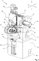
- FIG. 12 shows a perspective front view of an embodiment of a manufacturing system denoted by 120.
- the manufacturing system 120 has a modular structure in the exemplary embodiment.
- the manufacturing system 120 has at least one machining cell 122, which is provided with a machine tool 10, cf
- a machine tool 10 cf
- FIG. 12 shows a perspective front view of an embodiment of a manufacturing system denoted by 120.
- the manufacturing system 120 has a modular structure in the exemplary embodiment.
- the manufacturing system 120 has at least one machining cell 122, which is provided with a machine tool 10, cf
- the exemplary description of the machine tool 10 based on figures 1 and 2 .
- the manufacturing system 120 also includes a handling cell 124 and a set-up cell 126.
- the handling cell 124 is used primarily (primary function) to transfer workpieces 100 (or their blanks 102), ie to change workpieces.
- the set-up cell 126 serves primarily (primary function) to change tools.
- the machine tool 10 is arranged between the handling cell 124 and the set-up cell 126 .
- the manufacturing system 120 has a common base 130 for the processing cell 122 , the handling cell 124 and the set-up cell 126 .
- a housing 132 is provided that is designed approximately like a cabinet.
- the housing 132 is provided with a base 134 and a structure 136 . This applies in each case to the processing cell 122, the handling cell 124 and the set-up cell 126.
- the manufacturing system 120 with the housing 132 is designed to be approximately man-high.
- man-high means that the respective structure 136 can be easily reached by a standing operator.
- the respective substructure 134 is used, for example, to accommodate auxiliary units, auxiliary components, energy supply, control technology and the like.
- the substructure 134 is designed approximately as high as a table.
- the superstructure 136 is (taking into account the substructure 134) designed approximately as high as a cupboard.
- the manufacturing system 120 has a cabinet-like layout with a substructure 134 and a superstructure 136 , with the machine tool 10 defining a working space 144 with its travel axes, which is located in the superstructure 136 .
- structural components of the machine tool 10 compare in particular the frame block 18 and the slides 22, 28, 32 in 1 and 2 , arranged in the superstructure 136, i.e. in the upper section of the cabinet-like housing 132.
- a machining tool 46 held on the machine tool 10 and a workpiece holder 60 for receiving a workpiece 100 can be moved relative to one another in the working space 144 in order to machine the workpiece 100 .
- the workpiece holder 60 is arranged on a table 146 .
- the table 146 is associated with the C-axis, for example, but this is not to be understood as limiting.
- FIG. 4 shows a perspective view of the front of the manufacturing system 120.
- the manufacturing system 120 is designed in such a way that an operator standing frontally in front of the housing 132 can easily access and see relevant sections of the processing cell 122, the handling cell 124 and the set-up cell 126. This is made possible by corresponding viewing windows in the respective (upper) structure 136 of the processing cell 122, the handling cell 124 and the set-up cell 126.
- a control device is indicated with 48, which is designed here as a control panel, touch screen or the like.
- the processing cell 122, the handling cell 124 and the set-up cell 122 are each accessible via doors 138, 140, 142 in the structure 136.
- the processing cell 122, the handling cell 124 and the set-up cell 122 can also be referred to as modules of the manufacturing system 120.
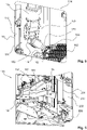
- the handling cell 124 comprises a handling unit 150, which is designed as a robot 152 in the exemplary embodiment.
- the robot 152 is designed as an articulated arm robot 152, for example.
- the robot 152 is suspended and supported on an upper base 154 .
- the robot 152 has different degrees of freedom of movement for moving workpieces 100 .
- the handling unit 150 carries a double gripper 156. In this way, the workpiece change is accelerated when a finished workpiece 100 can be removed from the machine tool 10 with one gripper and a new workpiece 100 can be exchanged with the other gripper.
- figure 5 shows a workpiece carrier 162, which is provided as a tray or tray with a large number of storage locations for blanks 102 or workpieces 100.
- the handling unit 150 of the handling cell 124 can remove workpieces from the workpiece carrier 162 and transfer them to the machine tool 10 .
- the handling cell 124 can be designed to accommodate a workpiece carrier 162 or a plurality of workpiece carriers 162, see also 7 .
- FIG. 5 further illustrates an interface, designated 170, between the handling cell 124 and the processing cell 122.
- the interface 170 comprises a door 172 which is provided with a drive 174.
- the door 172 is designed as a vertically movable sliding door, similar to a guillotine.
- the door 172 is movable between a closed position and an open position.
- the closed position is an upper position and the open position is a lower position.
- the handling unit 150 can be moved at least partially through the open door 172 in the direction of the working space 144 of the machine tool 10 in the machining cell 122 .
- FIG 5 176 indicates a discharge as an example.
- the discharge 176 is designed as a chute for discharging residual pieces 106 (also referred to as slugs).
- the discharge 176 can be used, for example, when the workpiece 100 in the machine tool 10 is finally separated from the surrounding edge (offcut 106) of the blank 102.
- the handling unit 150 can be used to mechanically grip the (for example ring-shaped) remnant 106 and transfer it to the discharge 176 .
- the handling unit 150 can be used to separate the workpiece 100 from the remnant 106 (for example the round 104 according to 3 ) by means of suction grippers or mechanically and deposit it in a free space/seat of a workpiece carrier 162.
- the set-up cell 126 includes a handling manipulator 180, which is designed as a so-called SCARA robot 182 in the exemplary embodiment.
- a SCARA robot 182 is an articulated arm robot with several horizontally oriented swivel axes 186, see also 7 .
- the handling manipulator 180 can be moved along a vertical guide 178 within the set-up cell 126 by a linear drive.
- An interface 184 is provided at a working end of the handling manipulator 180 .
- the interface 184 is used, for example, to couple a double gripper 188, which is 6 is shown in a parking position away from interface 184 .
- the handling manipulator 180 can exchange machining tools 46 between the set-up cell 126 and the machine tool 10 with the double gripper 188 .
- 192 indicate different storage locations for processing tools 46, which can accommodate processing tools 46 individually or in blocks.
- the interface 200 comprises a door 202 which is provided with a drive 204.
- the door 202 is designed as a vertically movable sliding door, similar to a guillotine.
- the door 202 is movable between a closed position and an open position. In the exemplary embodiment, the closed position is a lower position and the open position is an upper position.
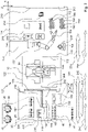
- FIG. 7 shows a schematic front view of the already based on the Figures 4-6 illustrated manufacturing system 120 with the modular cells 122, 124, 126.
- the processing cell 122 and in particular the working space 144 of the machine tool 10 are small compared to the dimensions of the handling cell 124. This also applies at least in part to a comparison of the processing cell 122 and the working space 144 with the dimensions of the setup cell 126.
- An interface 170 with a door 172 is arranged between the processing cell 122 and the handling cell 124 .
- An interface 200 with a door 202 is arranged between the processing cell 122 and the set-up cell 126 .
- the handling cell 124 also has a further interface 210 with a door 212 .
- the interface 210 can also be referred to as a transfer interface.
- the interface 210 is used, for example, for a transfer of workpiece carriers 162 that are equipped with a plurality or multiplicity of workpieces 100 .
- the handling cell 124 in the exemplary embodiment has buffer stores 164, 166, which are each provided with a support 168 for accommodating a workpiece carrier 162.
- the handling unit 150 can use the double gripper 156 to remove workpieces 100 from one of the workpiece carriers 162 and carry out a workpiece change on the workpiece holder 60 of the machine tool 10; a machined workpiece 100 can then be placed back in one of the workpiece carriers 162. The workpiece is changed via the interface 170.
- a reference part 218 is arranged in the handling cell 124 in the exemplary embodiment.
- the reference part 218 is used, for example, as a reference stop for aligning and centering a workpiece 100 before machining.
- the handling unit 150 with the double gripper 156 can remove workpieces 100 from a workpiece carrier 162 despite a comparatively imprecise orientation and align them with great precision on the reference part 218 before changing them into the machine tool 10 . This increases the positioning accuracy despite a comparatively imprecise orientation of the plurality/multiple workpieces 100 in the workpiece carrier 162.
- auxiliary store designated 214 in the handling cell 124 is also indicated.
- Auxiliary storage 214 may also be referred to as quarantine storage.
- the auxiliary memory 214 is used, for example, to temporarily hold a specific number of workpieces 100. This can be done, for example, for quality assurance purposes.
- a monitoring station 216 is provided in the handling cell 124 .
- the monitoring station 216 is designed as an optical monitoring station. This is not to be understood as limiting.
- the monitoring station 216 allows workpieces 100 to be checked close to production before they are released through the transfer interface 210 . Functional coupling between the monitoring station 216 and the auxiliary storage 214 is possible if workpieces 100 to be checked are stored in the auxiliary storage 214 .
- a suction gripper 158 is suitable for handling machined workpieces 100, for example.
- a machined workpiece 100 can be held fluidically with a suction gripper 158 . This is particularly gentle on the material.
- the use of a suction gripper 158 is appropriate, for example, when the workpiece 100 is completely separated from its edge (offcut 106).
- an arrow labeled 234 illustrates a primary function of the handling unit 150 of the handling cell 124.
- the primary function 234 is the workpiece change.
- a secondary gripper 230 is provided, which can be used for the handling unit 150 as required. With the secondary gripper 230, the handling unit 150 can change processing tools 46 instead of workpieces 100.
- the handling cell 124 and the set-up cell 126 are coupled to the processing cell 122 on opposite sides. At the in 7 In the configuration shown, this means that the machine tool 10 and in particular its working space 144 are accessible from the front. In the case of comparatively small workspaces 144 in particular, good visibility and good accessibility are helpful.
- the set-up cell 126 is provided with the handling manipulator 180 which, in the exemplary embodiment, has pivot axes 186 which are parallel to the viewing plane according to 7 are oriented.
- a gripper for example the double gripper 188, can be attached to the interface 184 of the handling manipulator.
- the double gripper 188 is in 7 shown in two views (side and top) for illustrative purposes.
- Machining tools 46 can be exchanged between the set-up cell 126 and the machine tool 10 in the machining cell 122 with the double gripper 188 .
- Various storage locations 190 , 192 are provided in the set-up cell 126 for the processing tools 46 .
- Memory locations 190, 192 are in 7 shown in two views (side and top) for illustrative purposes.
- Storage space 190 has a number of individual locations, each for accommodating individual machining tools 46 (in 7 four machining tools 46 are stored in memory location 190). These are, for example, machining tools 46 with a standardized taper shank.
- the storage space 192 has disk-like or turret-like tool sets 196 with a plurality of individual receiving seats 198 for machining tools 46 .
- the machining tools 46 in the tool sets 196 can be transferred in blocks.
- the interface 184 of the handling manipulator 180 can grip and hold the tool sets 196 directly. In this way, the handling manipulator 180 can be used for block set-up. This includes, for example, a transfer of loaded or unloaded tool sets 196 through an interface 220 provided with a door 222 .
- an arrow labeled 236 illustrates a primary function of the handling manipulator 180 of the set-up cell 126.
- the primary function 236 is the tool change.
- a secondary function 240 relates to block setup, i.e. changing complete tool sets 196.
- Another secondary function 242 relates, for example, to a workpiece change by the handling manipulator 180 the set-up cell 126.
- a secondary gripper 232 is provided in the set-up cell 126, which is designed for receiving and handling workpieces 100. In this way, the handling manipulator 180 of the set-up cell 126 can, if required, transfer at least individual workpieces 100 to the machine tool 10 in the machining cell 122 or remove them from there.
- a secondary function 244 which includes changing pallets or clamping devices by the handling manipulator 180 of the set-up cell 126 .
- 246 is in 7 memory for such devices 248 is indicated.
- Such a device (clamping device) 248 can be designed as part of the workpiece holder 60 or can be coupled to the workpiece holder 60 in some other way.
- a device change by the handling manipulator 180 of the set-up cell 126 is appropriate, for example, when there is a change between different workpiece types or workpiece dimensions.
- the machine tool 10 has a table for receiving workpieces 100, which is equipped with a device 248 in order to be able to hold and clamp the workpieces 100.
- the machine-remote interface 220 of the set-up cell 126 is opposite the machine-side interface 200 .
- the machine-remote interface 210 of the handling cell 124 is opposite the machine-side interface 170 .
- the handling cell 124 serves as a “mediator” between the machine tool 10 and other handling technology for workpiece handling.
- the set-up cell 126 serves as a "intermediary" between the machine tool 10 and other handling technology for tool handling.
- a combined transfer and storage device 252 (hereinafter: device) is described, which can be combined with at least one machine tool 10 or at least one manufacturing system 120 to form a manufacturing system 250.
- the device 252 can be used for storage purposes as well as for transfer purposes.
- the device can be coupled in a suitable manner to the at least one machine tool 10, so that a partially automated or highly automated workpiece change is made possible.
- the device 252 comprises a memory level 260 with a plurality of memories 270.
- the term memory level is to be understood functionally.
- the stores 270 are, for example, one or more shelf stores.
- the device 252 includes a housing 262 that houses the memories 270 of the memory plane 260 . In the housing 262 further elements of the device 252 are accommodated.
- the housing has a longitudinal extent (compare the double-headed arrow 264, which illustrates a longitudinal direction) that is significantly greater than the transverse extent (compare the double-headed arrow 266, which illustrates a transverse direction) and significantly greater than the vertical dimension (compare the double-headed arrow 268, which illustrates a vertical direction illustrated) is.
- the vertical extent (arrow 268) is also greater than the transverse extent (arrow 266).
- the stores 270 have a plurality of storage locations 272 arranged one above the other for receiving workpiece carriers 162.
- the workpiece carriers 162 are each used to hold a large number or plurality of workpieces 100.
- the storage locations 272 each include supports 274 for holding workpiece carriers 162, see also here 9 and 10 .
- the device 252 has a loading interface 280 on one end face.
- a driverless transport vehicle 290 has driven up to the loading interface 280 and coupled to the device 252 there.
- Workpiece carriers 162 can be introduced into the device 252 or removed from the device 252 via the loading interface 280 .
- the transport vehicle 290 is designed as a driverless transport vehicle (AGV) and is provided with a plurality of workpiece carriers 162 which are arranged one above the other on a frame 292 .
- AGV driverless transport vehicle
- the workpiece carrier 162 is transferred through the loading interface 280 when the loading interface 280 is in an open state.
- the gate 282 forms a vertical closing plane.
- the gate 282 can be moved between an open and a closed condition.
- the gate 282 is moved under an upper side 286 of the housing 262 at least in sections.
- the segments 284 of the gate 282 are guided under the roof (the upper side 286) of the housing 262 of the device 252 in the opened position and are held if necessary. This can result in the floor area and the lateral sides around the loading interface 280 being easily accessible when the gate 282 is in the open state.
- the device 252 comprises a transfer device 300 which comprises a longitudinal drive 302 which has a carriage which can be moved along a guide 304 which extends in the longitudinal direction 264 .
- the longitudinal drive 302 is guided on the bottom side in the exemplary embodiment.
- the longitudinal drive 302 carries a traveling column 308. The traveling column can be moved translationally in the longitudinal direction 264 by the transfer device 300.
- the transfer device 300 carries a handling device 312 which is designed for handling workpiece carriers 162 .
- the handling device 312 can be moved vertically (arrow 268) along a vertical guide on the traveling stand 308 via a vertical drive 310.
- the vertical drive 310 can also be referred to as a lifting drive.
- the transfer device 300 can move the handling device 312 in the longitudinal direction 264 as required between the stores 270, the loading interface 280 and at least one processing interface 328.
- FIG. 9 shows a perspective enlarged view of the transfer device 300 and in particular of the handling device 312 accommodated thereon.
- the handling device 312 includes a console 320 which can be moved vertically by the vertical drive 310 .
- the console 320 carries a table 322 which can be pivoted about a vertically oriented axis of rotation by a rotary drive 324 . In this way, the table 322 can be rotated in a horizontal plane.
- the table 322 carries a linear drive 330.
- the linear drive 330 is designed as a telescoping linear drive.
- the linear actuator 330 includes a base guide 332 that sits on the table 322 .
- a telescopic guide 334 is accommodated and displaceably mounted on the base guide 332 .
- the telescopic guide 334 comprises a first guide section 336 and a second guide section 338 .
- the first guide section 336 faces the base guide 332 .
- the second guide section 338 faces a carriage 340 .
- the two guide sections 336, 338 extend parallel to one another. In this way, the effective travel of the linear drive 330 is increased.
- the linear drive 330 can be pivoted overall via the rotary drive 324 .
- the carriage 340 is also pivoted.
- the carriage 340 can be moved linearly by the linear drive 330 .
- the carriage 340 carries a bracket 346, which in turn carries a carrier 352 designed as a double carrier.
- a further rotary drive 348 with a vertically oriented axis of rotation is also arranged between the console 346 and the carrier 352 .
- the carrier 352 is designed as a double carrier, which is symmetrical to a extends the plane of symmetry, which intersects the axis of rotation of the rotary drive 348, for example.
- the carrier 352 has two receiving locations 354, 356, each of which can receive a workpiece carrier 162.
- the receiving locations 354, 356 are each slightly inclined relative to the horizontal.
- the inclination of the receiving places 354, 356 is adapted to the inclination of the supports 274 in the stores 270.
- the receiving locations 354, 356 are formed by forks that can reach under a workpiece carrier 162.
- the double beam 352 has an H-shape, for example.
- the (double) carrier 352 allows workpiece carriers 162 to be changed quickly because two receiving locations 352, 354 are provided and because the rotary drive 348 allows the carrier 352 to rotate about an axis of symmetry.
- the rotary drive 324 coupled to the table 322 allows the linear drive 330 to be pivoted, for example between an orientation towards a first side (left side 360 in 10 ), to an opposite, second side (right side 362 in 10 ) and, if necessary, an end face (compare the two end faces 370, 372 in 11 ).
- the rotary drive 324 can be pivoted by +90° and -90° starting from a 0° position (parallel to the longitudinal direction 264) in order to approach the sides 360, 362.
- the design of the linear drive 330 as a telescoping linear drive allows sufficiently large travel distances even with a limited transverse extension (transverse direction 266) of the device 252 or of its housing 262. Illustrated in this context 10 example the space conditions in the embodiment.
- the transfer device 300 with the handling device 312 can be moved between stores 270 on the first side 360 and the second side 362 and, if necessary, deposit and pick up workpiece carriers 162 there in the storage level 260 .
- a change of workpiece carriers 162 via the loading interface 280 (cf 8 ) is possible.
- the device 252 serves not only as a transfer device, but also as a storage device with a considerable storage capacity in the storage plane 260.
- FIG. 12 illustrates, in a schematic, simplified plan view, an exemplary configuration of a manufacturing facility 250 provided with an apparatus 252 configured in accordance with the disclosure.
- the facility 250 further includes a plurality of manufacturing systems 120 configured in accordance with the disclosure. It results in 11 a topology similar to a bus topology. It goes without saying that the position of memories 270 or production systems 120 can be selected with sufficient flexibility.
- the manufacturing systems 120 are each coupled with their transfer interface 210 to one of the processing interfaces 328 of the device 252 . In 11 some of the memories 270 are occupied by workpiece carriers 162, others are not.
- workpieces 100 are exchanged between device 252 and machine tool 10 in processing cell 122 indirectly using handling cell 124 with handling unit 150.
- device 252 extends between a first end face 370 and a second end face 372.
- a loading interface 280 for coupling a vehicle 290 is provided on at least one of the two end faces 370, 372.
- transfer device 300 with handling device 312 transfers workpiece carriers 162.
- 11 12 further illustrates the lateral accessibility of the storage 270.
- an operator is indicated on the side 362 (here: right side) with 382, who is standing upright in front of one of the storage 270 in a top view.
- the memories 270 of the memory level 260 are accessible via doors 380 .
- the device 252 can also be loaded in this way. At least some of the memories 270 of the memory tier 260 are accessible to operators 382 from the side.
- the various manufacturing systems 120 can carry out manufacturing steps that build on one another.
- the transfer between individual manufacturing systems 120 and, if necessary, intermediate storage is carried out by the combined transfer and storage device 252.
- parallel processing of similar production steps by a plurality of production systems 120 to increase the throughput of the entire system 250 is also conceivable.
- the tool change takes place primarily via the respective setup cell 126 of the production system 120, in particular via the handling manipulator 180 provided there.
- the loading of the setup cell 126 takes place via the interface 220, which is functionally remote from the device 252.
Landscapes
- Engineering & Computer Science (AREA)
- Mechanical Engineering (AREA)
- Multi-Process Working Machines And Systems (AREA)
- Feeding Of Workpieces (AREA)
Applications Claiming Priority (1)
| Application Number | Priority Date | Filing Date | Title |
|---|---|---|---|
| DE102021113892.2A DE102021113892B4 (de) | 2021-05-28 | 2021-05-28 | Kombinierte Transfer- und Speichervorrichtung sowie Anlage zur spanenden Fertigung |
Publications (1)
| Publication Number | Publication Date |
|---|---|
| EP4094885A1 true EP4094885A1 (fr) | 2022-11-30 |
Family
ID=81748585
Family Applications (1)
| Application Number | Title | Priority Date | Filing Date |
|---|---|---|---|
| EP22174063.2A Pending EP4094885A1 (fr) | 2021-05-28 | 2022-05-18 | Dispositif combiné de transfert et de stockage, ainsi qu'installation d'usinage par enlèvement des copeaux |
Country Status (4)
| Country | Link |
|---|---|
| US (3) | US11980989B2 (fr) |
| EP (1) | EP4094885A1 (fr) |
| CN (1) | CN115401501B (fr) |
| DE (1) | DE102021113892B4 (fr) |
Cited By (3)
| Publication number | Priority date | Publication date | Assignee | Title |
|---|---|---|---|---|
| CN118143671A (zh) * | 2024-03-15 | 2024-06-07 | 南京宁庆数控机床制造有限公司 | 一种大扭矩高刚性五轴头 |
| EP4681869A1 (fr) * | 2024-07-18 | 2026-01-21 | United Machining Mill AG | Système de transport automatique d'une palette appliquée dans une machine-outil |
| EP4737068A1 (fr) * | 2024-10-30 | 2026-05-06 | MG Beteiligungsgesellschaft mbH | Procédé de manipulation automatisée de pièces, module d'automatisation et système constitué d'un module d'automatisation et d'un dispositif de transfert |
Families Citing this family (2)
| Publication number | Priority date | Publication date | Assignee | Title |
|---|---|---|---|---|
| DE102022123232B4 (de) * | 2022-09-12 | 2025-10-02 | Chiron Group Se | Vorrichtung zur Späneabführung für eine Werkzeugmaschine und Fertigungssystem |
| CN116713814B (zh) * | 2023-05-12 | 2025-09-02 | 江苏恒力组合机床有限公司 | 一种大型混联高速五轴加工中心 |
Citations (8)
| Publication number | Priority date | Publication date | Assignee | Title |
|---|---|---|---|---|
| DE3543209A1 (de) | 1985-12-06 | 1987-06-11 | Kloeckner Humboldt Deutz Ag | Flexibles fertigungssystem |
| DE102005034079A1 (de) | 2005-07-21 | 2007-01-25 | Gebr. Heller Maschinenfabrik Gmbh | Fertigungssystem |
| EP2036664A1 (fr) | 2007-09-13 | 2009-03-18 | Promot Automation GmbH | Installation de traitement pour pièces à usiner |
| EP2227349B1 (fr) | 2007-12-07 | 2011-04-27 | Dieter Faude | Dispositif de protection pour un poste de processus, et procédé de chargement et/ou de déchargement automatique d'un poste de processus |
| DE202013008677U1 (de) * | 2013-09-24 | 2013-10-24 | Winkel Gmbh | Pufferzelle |
| DE102014114258A1 (de) | 2014-02-21 | 2015-08-27 | Sk-Technologies Ug (Haftungsbeschränkt) | Roboterzelle zum hauptzeitparallelen Be- und Entladen von Einzelplatz-Zerspannungsmaschinen |
| DE202017102297U1 (de) * | 2016-04-19 | 2017-07-17 | Haute Ecole Arc | Mikroanlage |
| CN110315380A (zh) | 2019-08-08 | 2019-10-11 | 江苏汇博机器人技术股份有限公司 | 一种用于实训考核的机器人上下料系统 |
Family Cites Families (34)
| Publication number | Priority date | Publication date | Assignee | Title |
|---|---|---|---|---|
| GB1193860A (en) * | 1966-11-26 | 1970-06-03 | American Mach & Foundry | System for Stacking and Grouping, or the Like |
| DE2717011A1 (de) * | 1977-04-18 | 1978-10-19 | Alfa Laval Ab | Vorrichtung zum lagern von stueckgut, insbesondere packungen, mit mehreren, jeweils eine vielzahl von packungen aufnehmenden behaeltern und verfahren zum handhaben einer solchen vorrichtung |
| US4736512A (en) * | 1986-08-29 | 1988-04-12 | The Monarch Machine Tool Company | Tool and work changer assembly |
| US5271139A (en) * | 1989-04-04 | 1993-12-21 | Walter Sticht | Production installation |
| DE4422416C1 (de) * | 1994-06-29 | 1996-01-11 | Magnus Dipl Ing Gruener | Bearbeitungszentrum |
| FI112060B (fi) | 2000-06-21 | 2003-10-31 | Fastems Oy Ab | Integroitu käsittelyjärjestelmä työkappaleille ja materiaaleille |
| US6637097B2 (en) * | 2000-08-07 | 2003-10-28 | Toshiharu Miyano | System and method for processing elongate workpieces |
| DE10144248A1 (de) * | 2001-08-31 | 2003-03-27 | Felsomat Gmbh & Co Kg | Handhabungsvorrichtung |
| DE10144678A1 (de) * | 2001-09-11 | 2003-04-03 | Emag Maschfab Gmbh | Fräs-und Bohrbearbeitungszentrum |
| FR2846314B1 (fr) * | 2002-10-25 | 2005-08-19 | Bsn Glasspack | Machine de deplacement de recipients devant des postes de controle |
| DE10253224A1 (de) * | 2002-11-15 | 2004-06-03 | Niles-Simmons Industrieanlagen Gmbh | Flexible Fertigungslinie |
| EP1607174A1 (fr) | 2004-06-15 | 2005-12-21 | Zimmer & Kreim GmbH & Co. KG | Dispositif pour chargement et déchargement d'outils dans/d'un magasin d'outils d'une machine-outil |
| GB0425142D0 (en) * | 2004-11-15 | 2004-12-15 | Arx Ltd | Apparatus for storing and dispensing packages |
| DE102005028358A1 (de) * | 2005-06-18 | 2006-12-21 | Alfing Keßler Sondermaschinen GmbH | Bearbeitungsmaschinenanordnung mit Roboter und Werkzeugmagazin |
| DE102006025620A1 (de) * | 2006-05-24 | 2007-11-29 | SSI Schäfer Noell GmbH Lager- und Systemtechnik | Regallager und Kommissionierverfahren |
| US8276739B2 (en) * | 2007-01-25 | 2012-10-02 | Bastian Material Handling, Llc | Three-dimensional automated pick module |
| DE102007024457B4 (de) * | 2007-05-25 | 2009-04-16 | Hans Lingl Anlagenbau Und Verfahrenstechnik Gmbh & Co. Kg | Be- und Entladestation für ein Trocknergestell für Formlinge, insbesondere aus tonhaltigem oder ähnlichem Material |
| WO2010070915A1 (fr) * | 2008-12-19 | 2010-06-24 | 株式会社川渕機械技術研究所 | Mécanisme extensible se déplaçant de manière linéaire et bras de robot équipé d'un mécanisme extensible se déplaçant de manière linéaire |
| DE102009035804B3 (de) * | 2009-07-31 | 2010-08-12 | Trumpf Werkzeugmaschinen Gmbh + Co. Kg | Maschinelle Werkstückbearbeitungsanlage und Paletten-Auflage für eine maschinelle Werkstückbearbeitungsanlage |
| DE102009040811A1 (de) | 2009-09-10 | 2011-03-17 | A2O Ag | Modulare Anlage zur Handhabung von Gegenständen |
| DE102011103321B4 (de) * | 2011-05-27 | 2015-07-16 | Emag Holding Gmbh | Selbstladende Werkzeugmaschine mit vertikaler Werkzeugspindel |
| AT511623B1 (de) * | 2011-07-08 | 2016-01-15 | Tgw Mechanics Gmbh | Regallagersystem |
| DE102012018226B4 (de) * | 2012-09-15 | 2024-03-28 | Emag Holding Gmbh | Werkzeugmaschine mit Schutzabdeckung |
| JP6397185B2 (ja) * | 2013-12-10 | 2018-09-26 | 川崎重工業株式会社 | ロボットセル |
| US10345526B2 (en) * | 2014-12-14 | 2019-07-09 | Telescent Inc. | High reliability robotic cross-connect systems |
| DE102016210508A1 (de) * | 2016-06-14 | 2017-12-14 | Gildemeister Drehmaschinen Gmbh | Handhabungsvorrichtung zum Einsatz an einer Werkzeugmaschine |
| DE102016120132A1 (de) * | 2016-10-21 | 2018-04-26 | Trumpf Werkzeugmaschinen Gmbh + Co. Kg | Werkstücksammelstelleneinheit und Verfahren zur Unterstützung der Bearbeitung von Werkstücken |
| AT519480B1 (de) * | 2017-02-08 | 2018-07-15 | Trumpf Maschinen Austria Gmbh & Co Kg | Biegewerkzeug-Speichervorrichtung |
| DE102017127116B4 (de) * | 2017-11-17 | 2019-07-11 | Scherer-Feinbau Gmbh | Werkzeugmaschine, Fertigungszelle sowie Verfahren zum Betreiben einer Fertigungszelle |
| CN109940440A (zh) * | 2017-12-21 | 2019-06-28 | 王芳 | 一种气动加工设备 |
| US11351643B2 (en) * | 2018-02-21 | 2022-06-07 | Navarro IP, LLC | Universal machining apparatus and control system |
| CN108655494B (zh) * | 2018-06-25 | 2023-09-08 | 浙江畅尔智能装备股份有限公司 | 一种涡轮盘榫槽拉削的自动化生产线 |
| US11612927B2 (en) * | 2018-07-06 | 2023-03-28 | Ats Automation Tooling Systems Inc. | System and method for flexible manufacturing |
| DE102019111873A1 (de) * | 2019-05-07 | 2020-11-12 | Chiron-Werke Gmbh & Co. Kg | Werkzeugmaschine mit Portal |
-
2021
- 2021-05-28 DE DE102021113892.2A patent/DE102021113892B4/de active Active
-
2022
- 2022-05-18 EP EP22174063.2A patent/EP4094885A1/fr active Pending
- 2022-05-26 CN CN202210595672.6A patent/CN115401501B/zh active Active
- 2022-05-27 US US17/826,785 patent/US11980989B2/en active Active
-
2024
- 2024-04-10 US US18/631,932 patent/US20240253172A1/en not_active Abandoned
-
2025
- 2025-04-14 US US19/178,002 patent/US20250235971A1/en active Pending
Patent Citations (9)
| Publication number | Priority date | Publication date | Assignee | Title |
|---|---|---|---|---|
| DE3543209A1 (de) | 1985-12-06 | 1987-06-11 | Kloeckner Humboldt Deutz Ag | Flexibles fertigungssystem |
| DE102005034079A1 (de) | 2005-07-21 | 2007-01-25 | Gebr. Heller Maschinenfabrik Gmbh | Fertigungssystem |
| EP2036664A1 (fr) | 2007-09-13 | 2009-03-18 | Promot Automation GmbH | Installation de traitement pour pièces à usiner |
| EP2227349B1 (fr) | 2007-12-07 | 2011-04-27 | Dieter Faude | Dispositif de protection pour un poste de processus, et procédé de chargement et/ou de déchargement automatique d'un poste de processus |
| DE202013008677U1 (de) * | 2013-09-24 | 2013-10-24 | Winkel Gmbh | Pufferzelle |
| DE102014114258A1 (de) | 2014-02-21 | 2015-08-27 | Sk-Technologies Ug (Haftungsbeschränkt) | Roboterzelle zum hauptzeitparallelen Be- und Entladen von Einzelplatz-Zerspannungsmaschinen |
| DE202017102297U1 (de) * | 2016-04-19 | 2017-07-17 | Haute Ecole Arc | Mikroanlage |
| US20190084102A1 (en) | 2016-04-19 | 2019-03-21 | Haute Ecole Arc | Five axis machine tool |
| CN110315380A (zh) | 2019-08-08 | 2019-10-11 | 江苏汇博机器人技术股份有限公司 | 一种用于实训考核的机器人上下料系统 |
Cited By (3)
| Publication number | Priority date | Publication date | Assignee | Title |
|---|---|---|---|---|
| CN118143671A (zh) * | 2024-03-15 | 2024-06-07 | 南京宁庆数控机床制造有限公司 | 一种大扭矩高刚性五轴头 |
| EP4681869A1 (fr) * | 2024-07-18 | 2026-01-21 | United Machining Mill AG | Système de transport automatique d'une palette appliquée dans une machine-outil |
| EP4737068A1 (fr) * | 2024-10-30 | 2026-05-06 | MG Beteiligungsgesellschaft mbH | Procédé de manipulation automatisée de pièces, module d'automatisation et système constitué d'un module d'automatisation et d'un dispositif de transfert |
Also Published As
| Publication number | Publication date |
|---|---|
| US11980989B2 (en) | 2024-05-14 |
| CN115401501B (zh) | 2024-07-05 |
| US20240253172A1 (en) | 2024-08-01 |
| CN115401501A (zh) | 2022-11-29 |
| US20250235971A1 (en) | 2025-07-24 |
| DE102021113892B4 (de) | 2024-05-16 |
| DE102021113892A1 (de) | 2022-12-01 |
| US20220379420A1 (en) | 2022-12-01 |
Similar Documents
| Publication | Publication Date | Title |
|---|---|---|
| DE102021113892B4 (de) | Kombinierte Transfer- und Speichervorrichtung sowie Anlage zur spanenden Fertigung | |
| EP4094884A1 (fr) | Système d'usinage et installation d'usinage par enlèvement des copeaux | |
| EP3147073B1 (fr) | Machine-outil, en particulier fraiseuse multi-broches | |
| EP2812152B1 (fr) | Machine de rodage à plusieurs postes de travail et table rotative | |
| EP3195977B1 (fr) | Machine-outil, en particulier fraiseuse multibroche | |
| EP0977651B1 (fr) | Procede et dispositif de fabrication de pieces complexes | |
| DE102019111873A1 (de) | Werkzeugmaschine mit Portal | |
| EP3195976B1 (fr) | Machine-outil, en particulier fraiseuse multibroche | |
| DE102019120681B4 (de) | Werkzeugmaschine | |
| EP1291122A2 (fr) | Centre d'usinage pour fraisage et forage | |
| EP0568798A1 (fr) | Centre d'usinage formée par un assemblage de modules | |
| DE3427245A1 (de) | Werkzeugmaschine | |
| EP2945776B1 (fr) | Machine-outil avec échangeur de palettes | |
| EP2753454B1 (fr) | Machine-outil | |
| WO2006042645A1 (fr) | Machine-outil tres flexible comprenant plusieurs supports de piece | |
| DE202010000754U1 (de) | Bearbeitungszentrum | |
| EP2829358B1 (fr) | Changeur de pièce pour le changement automatique de pièces ou de palettes dans un centre d'usinage | |
| EP3159102A1 (fr) | Machine-outil avec dispositif de commande et procédé pour machine-outil | |
| DE19747995C2 (de) | Selbstladendes Bearbeitungszentrum mit Werkstück- und Werkzeugmagazinen | |
| EP4461458B1 (fr) | Machine-outil et procédé d'usinage de pièces | |
| DE20115005U1 (de) | Fräs- und Bohrbearbeitungszentrum | |
| EP4335584A1 (fr) | Cellule de manipulation pour une machine-outil et système de fabrication | |
| DE4414844A1 (de) | Zwei Werkzeugmaschinen mit gemeinsamem Werkzeugwechsler umfassende Bearbeitungszelle | |
| DE102008024397A1 (de) | Wandelbares Produktionssystem und Transfermodul hierzu | |
| EP4501533A2 (fr) | Machine-outil, installation de fabrication et procédé d'usinage de matériau en barre |
Legal Events
| Date | Code | Title | Description |
|---|---|---|---|
| PUAI | Public reference made under article 153(3) epc to a published international application that has entered the european phase |
Free format text: ORIGINAL CODE: 0009012 |
|
| STAA | Information on the status of an ep patent application or granted ep patent |
Free format text: STATUS: THE APPLICATION HAS BEEN PUBLISHED |
|
| AK | Designated contracting states |
Kind code of ref document: A1 Designated state(s): AL AT BE BG CH CY CZ DE DK EE ES FI FR GB GR HR HU IE IS IT LI LT LU LV MC MK MT NL NO PL PT RO RS SE SI SK SM TR |
|
| STAA | Information on the status of an ep patent application or granted ep patent |
Free format text: STATUS: REQUEST FOR EXAMINATION WAS MADE |
|
| 17P | Request for examination filed |
Effective date: 20230526 |
|
| RBV | Designated contracting states (corrected) |
Designated state(s): AL AT BE BG CH CY CZ DE DK EE ES FI FR GB GR HR HU IE IS IT LI LT LU LV MC MK MT NL NO PL PT RO RS SE SI SK SM TR |
|
| TPAC | Observations filed by third parties |
Free format text: ORIGINAL CODE: EPIDOSNTIPA |
|
| STAA | Information on the status of an ep patent application or granted ep patent |
Free format text: STATUS: EXAMINATION IS IN PROGRESS |
|
| 17Q | First examination report despatched |
Effective date: 20250521 |