EP4501533A2 - Machine-outil, installation de fabrication et procédé d'usinage de matériau en barre - Google Patents
Machine-outil, installation de fabrication et procédé d'usinage de matériau en barre Download PDFInfo
- Publication number
- EP4501533A2 EP4501533A2 EP24191479.5A EP24191479A EP4501533A2 EP 4501533 A2 EP4501533 A2 EP 4501533A2 EP 24191479 A EP24191479 A EP 24191479A EP 4501533 A2 EP4501533 A2 EP 4501533A2
- Authority
- EP
- European Patent Office
- Prior art keywords
- holding unit
- workpiece holding
- frame
- primary
- workpiece
- Prior art date
- Legal status (The legal status is an assumption and is not a legal conclusion. Google has not performed a legal analysis and makes no representation as to the accuracy of the status listed.)
- Pending
Links
Images


Classifications
-
- B—PERFORMING OPERATIONS; TRANSPORTING
- B23—MACHINE TOOLS; METAL-WORKING NOT OTHERWISE PROVIDED FOR
- B23Q—DETAILS, COMPONENTS, OR ACCESSORIES FOR MACHINE TOOLS, e.g. ARRANGEMENTS FOR COPYING OR CONTROLLING; MACHINE TOOLS IN GENERAL CHARACTERISED BY THE CONSTRUCTION OF PARTICULAR DETAILS OR COMPONENTS; COMBINATIONS OR ASSOCIATIONS OF METAL-WORKING MACHINES, NOT DIRECTED TO A PARTICULAR RESULT
- B23Q1/00—Members which are comprised in the general build-up of a form of machine, particularly relatively large fixed members
- B23Q1/01—Frames, beds, pillars or like members; Arrangement of ways
- B23Q1/015—Frames, beds, pillars
-
- B—PERFORMING OPERATIONS; TRANSPORTING
- B23—MACHINE TOOLS; METAL-WORKING NOT OTHERWISE PROVIDED FOR
- B23Q—DETAILS, COMPONENTS, OR ACCESSORIES FOR MACHINE TOOLS, e.g. ARRANGEMENTS FOR COPYING OR CONTROLLING; MACHINE TOOLS IN GENERAL CHARACTERISED BY THE CONSTRUCTION OF PARTICULAR DETAILS OR COMPONENTS; COMBINATIONS OR ASSOCIATIONS OF METAL-WORKING MACHINES, NOT DIRECTED TO A PARTICULAR RESULT
- B23Q1/00—Members which are comprised in the general build-up of a form of machine, particularly relatively large fixed members
- B23Q1/25—Movable or adjustable work or tool supports
- B23Q1/44—Movable or adjustable work or tool supports using particular mechanisms
- B23Q1/50—Movable or adjustable work or tool supports using particular mechanisms with rotating pairs only, the rotating pairs being the first two elements of the mechanism
- B23Q1/52—Movable or adjustable work or tool supports using particular mechanisms with rotating pairs only, the rotating pairs being the first two elements of the mechanism a single rotating pair
- B23Q1/525—Movable or adjustable work or tool supports using particular mechanisms with rotating pairs only, the rotating pairs being the first two elements of the mechanism a single rotating pair which is parallel to the working surface
-
- B—PERFORMING OPERATIONS; TRANSPORTING
- B23—MACHINE TOOLS; METAL-WORKING NOT OTHERWISE PROVIDED FOR
- B23Q—DETAILS, COMPONENTS, OR ACCESSORIES FOR MACHINE TOOLS, e.g. ARRANGEMENTS FOR COPYING OR CONTROLLING; MACHINE TOOLS IN GENERAL CHARACTERISED BY THE CONSTRUCTION OF PARTICULAR DETAILS OR COMPONENTS; COMBINATIONS OR ASSOCIATIONS OF METAL-WORKING MACHINES, NOT DIRECTED TO A PARTICULAR RESULT
- B23Q1/00—Members which are comprised in the general build-up of a form of machine, particularly relatively large fixed members
- B23Q1/25—Movable or adjustable work or tool supports
- B23Q1/44—Movable or adjustable work or tool supports using particular mechanisms
- B23Q1/50—Movable or adjustable work or tool supports using particular mechanisms with rotating pairs only, the rotating pairs being the first two elements of the mechanism
- B23Q1/54—Movable or adjustable work or tool supports using particular mechanisms with rotating pairs only, the rotating pairs being the first two elements of the mechanism two rotating pairs only
- B23Q1/5406—Movable or adjustable work or tool supports using particular mechanisms with rotating pairs only, the rotating pairs being the first two elements of the mechanism two rotating pairs only a single rotating pair followed perpendicularly by a single rotating pair
-
- B—PERFORMING OPERATIONS; TRANSPORTING
- B23—MACHINE TOOLS; METAL-WORKING NOT OTHERWISE PROVIDED FOR
- B23Q—DETAILS, COMPONENTS, OR ACCESSORIES FOR MACHINE TOOLS, e.g. ARRANGEMENTS FOR COPYING OR CONTROLLING; MACHINE TOOLS IN GENERAL CHARACTERISED BY THE CONSTRUCTION OF PARTICULAR DETAILS OR COMPONENTS; COMBINATIONS OR ASSOCIATIONS OF METAL-WORKING MACHINES, NOT DIRECTED TO A PARTICULAR RESULT
- B23Q1/00—Members which are comprised in the general build-up of a form of machine, particularly relatively large fixed members
- B23Q1/25—Movable or adjustable work or tool supports
- B23Q1/44—Movable or adjustable work or tool supports using particular mechanisms
- B23Q1/56—Movable or adjustable work or tool supports using particular mechanisms with sliding pairs only, the sliding pairs being the first two elements of the mechanism
- B23Q1/60—Movable or adjustable work or tool supports using particular mechanisms with sliding pairs only, the sliding pairs being the first two elements of the mechanism two sliding pairs only, the sliding pairs being the first two elements of the mechanism
- B23Q1/62—Movable or adjustable work or tool supports using particular mechanisms with sliding pairs only, the sliding pairs being the first two elements of the mechanism two sliding pairs only, the sliding pairs being the first two elements of the mechanism with perpendicular axes, e.g. cross-slides
- B23Q1/621—Movable or adjustable work or tool supports using particular mechanisms with sliding pairs only, the sliding pairs being the first two elements of the mechanism two sliding pairs only, the sliding pairs being the first two elements of the mechanism with perpendicular axes, e.g. cross-slides a single sliding pair followed perpendicularly by a single sliding pair
- B23Q1/626—Movable or adjustable work or tool supports using particular mechanisms with sliding pairs only, the sliding pairs being the first two elements of the mechanism two sliding pairs only, the sliding pairs being the first two elements of the mechanism with perpendicular axes, e.g. cross-slides a single sliding pair followed perpendicularly by a single sliding pair followed perpendicularly by a single sliding pair
-
- B—PERFORMING OPERATIONS; TRANSPORTING
- B23—MACHINE TOOLS; METAL-WORKING NOT OTHERWISE PROVIDED FOR
- B23Q—DETAILS, COMPONENTS, OR ACCESSORIES FOR MACHINE TOOLS, e.g. ARRANGEMENTS FOR COPYING OR CONTROLLING; MACHINE TOOLS IN GENERAL CHARACTERISED BY THE CONSTRUCTION OF PARTICULAR DETAILS OR COMPONENTS; COMBINATIONS OR ASSOCIATIONS OF METAL-WORKING MACHINES, NOT DIRECTED TO A PARTICULAR RESULT
- B23Q2240/00—Machine tools specially suited for a specific kind of workpiece
- B23Q2240/007—Elongated workpieces
Definitions
- the present disclosure relates to a machine tool, a manufacturing plant and a method for machining bar stock.
- the machine tool has a frame, a tool spindle mounted on the frame, a primary workpiece holding unit mounted on the frame, which is designed as a turning spindle, and a secondary workpiece holding unit mounted on the frame, wherein the primary workpiece holding unit and the secondary workpiece holding unit face each other in at least one horizontal orientation and are oriented coaxially to each other.
- the machine tool and the manufacturing plant provided with such a machine tool are particularly suitable for machining bar stock.
- the machine tool is suitable for turning-milling and possibly even for complete machining.
- a machine tool for turning and milling which has a tool spindle, a first workpiece spindle and a second workpiece spindle.
- the tool spindle can be pivoted about a horizontal axis (B-axis).
- the second workpiece spindle is part of a headstock, which can also be pivoted about a horizontal axis parallel to it (B-axis).
- the first workpiece spindle cannot be pivoted about a horizontal axis parallel to it (B-axis).
- the second workpiece spindle can be used for changing workpieces. Milling in five axes can be achieved by the pivoting movement of the tool spindle.
- Keywords such as sustainability and resource efficiency are becoming increasingly important.
- the aim is to adapt machine tools to specific workpieces with regard to the work space, the required travel distances and/or the electrical connection power. This can prevent compact workpieces from being processed with excessively large machine tools. This applies, for example, to typical workpieces in the field of precision mechanics, medical technology, the jewelry industry and/or the watch industry. Other applications are conceivable. If there is a favorable relationship between the dimensions of the workpieces to be processed and the work space of the machine tool, the space consumption, energy consumption and other resource consumption by the machine tool can be optimized.
- the present disclosure is based on the object of providing a machine tool and a production plant with a machine tool which allow efficient machining with a compact design.
- the machine tool should be suitable for the complete machining of workpieces based on bar material.
- the semi-finished products used are bars with cross-sections with a diameter and/or edge dimension of less than 50 mm, less than 30 mm or even 26 mm or less. Workpieces that are manufactured on the basis of such semi-finished products should be able to be manufactured particularly efficiently with the machine tool.
- the concept of the machine tool preferably takes into account the desired compact design.
- the machine tool should have a favorable ratio of the work space provided and the area used/space used.
- a production system with such a machine tool and a workpiece magazine adapted to the design of the machine tool should be specified.
- a method for machining bar material that uses such a production system should be specified.
- the pivotability of the primary workpiece holding unit and the secondary workpiece holding unit allows a machine kinematics in which the tool spindle is moved exclusively in a translational manner.
- the tool spindle according to this embodiment is not provided with a pivot drive. It is understood that the tool spindle is designed to rotate a tool about a spindle axis.
- the tool spindle can therefore be designed to be compact. If a swivel drive is not used in the tool spindle, the tool spindle can still be designed to be movable in three translational axes. At the same time, inert masses can be limited because no complex swivel drive needs to be integrated into such a design. This can have a positive effect on the dynamics and acceleration behavior. Furthermore, the rigidity is increased in this way because the compact design leads to a significantly reduced tendency to deformation during machining.
- the travel paths in the X-direction, the Y-direction and the Z-direction can be adapted to the expected workpiece dimensions.
- Multi-sided machining in particular complete machining and/or six-sided machining, can be carried out with a single tool spindle. This can be done with high resource efficiency for example with regard to installation space, energy consumption and/or consumption of cooling lubricants (CLS).
- CLS cooling lubricants
- the machine tool is designed for turning and milling.
- complete machining can be carried out with the machine tool if the workpiece is transferred directly between the primary workpiece holding unit and the secondary workpiece holding unit without any further handling effort.
- the primary workpiece holding unit and the secondary workpiece holding unit face each other in at least one operating position and are oriented coaxially to each other and axially offset from each other.
- At least the primary workpiece holding unit is designed as a turning spindle. In this way, turning with a stationary tool is possible.
- the coaxial orientation can also be referred to as a common turning orientation.
- a workpiece can be fastened to both the primary workpiece holding unit and the secondary workpiece holding unit.
- the primary workpiece holding unit and the secondary workpiece holding unit can each hold the workpiece alone at least temporarily, so that corresponding end regions can be machined that are not accessible when the other workpiece holding unit engages the workpiece.
- the pivotability of the primary workpiece holding unit and the secondary workpiece holding unit can also be used for a workpiece transfer through the machine tool.
- the work area of the machine tool can be loaded through the primary workpiece holding unit.
- the primary workpiece holding unit is designed as a hollow spindle.
- the primary workpiece holding unit has, in addition to the primary swivel axis, another swivel axis (so-called A-axis), which is the turning spindle is provided.
- A-axis another swivel axis
- This enables five-axis machining of workpieces that are clamped in the turning spindle.
- the tool spindle can only be moved linearly and does not provide an additional swivel axis.
- the primary workpiece holding unit which is provided with a rotary spindle, provides a rotation axis.
- the secondary workpiece holding unit can also provide a rotation axis (in the form of a counter spindle), at least in exemplary embodiments.
- the machine tool according to the disclosure is suitable for turning and milling.
- the workpiece can be machined in four axes.
- the workpiece can be machined in five axes.
- the workpiece is transferred between the primary and secondary workpiece holding units, machining in six axes is possible.
- the longitudinal axis (rotation axis) of the workpiece is oriented parallel to the X-axis.
- the X-axis is oriented horizontally.
- the Y-axis is orthogonal to the X-axis and also oriented horizontally.
- the X-axis and the Y-axis form a horizontal plane.
- the Z-axis is oriented orthogonal to the X-axis and orthogonal to the Y-axis.
- the Z-axis is a vertical axis.
- a longitudinal axis (rotation axis) of the tool spindle is permanently oriented vertically and therefore parallel to the Z-axis.
- the Y-slide has an inclined bed on which the X-slide is guided.
- An X-guide is used to guide the X-slide.
- the inclination of the X-guide relative to the horizontal is approximately in the range between 30° and 60°, in particular in the range between 40° and 50°, in particular around 45°. This results in a compact and highly rigid design. This leads to a low tendency for the machine kinematics to deform when the machine tool is in operation.
- the frame has a flat bed on which the Y-slide is guided.
- a Y-guide is used to guide the Y-slide.
- the Y-guide is formed, for example, on an upper side of the machine frame.
- the X-slide has a vertical front wall on which the Z-slide is guided.
- the vertical front wall carries a Z-guide on which the Z-slide is guided.
- the vertical front wall faces the work area.
- the Z-slide carries the vertically oriented tool spindle.
- the travel path of the tool spindle in the X direction is greater than the travel path of the tool spindle in the Z direction. Furthermore, the travel path of the tool spindle in the Z direction is greater than the travel path of the tool spindle in the Y direction.
- the secondary workpiece holding unit can be moved translationally along a linear axis that is oriented parallel to the first horizontal axis.
- the secondary workpiece holding unit can be moved translationally in the X direction.
- a distance between the primary workpiece holding unit and the secondary workpiece holding unit can be changed in the X direction.
- This can also include, for example, back machining/end machining of the workpiece on its sixth side, which was previously covered by the primary workpiece holding unit.
- the secondary workpiece holding unit can be used during loading and/or unloading.
- the secondary workpiece holding unit can grip a front end of the semi-finished product and pull it along the first horizontal axis.
- the degrees of freedom of the primary workpiece holding unit and the secondary workpiece holding unit allow at least partially automated workpiece handling. In this way, a bar magazine (bar loader) coupled to the machine tool can be designed simply because the machine tool itself can take on transfer tasks with the given kinematics.
- the secondary workpiece holding unit can move the workpiece in the horizontal orientation relative to the primary workpiece holding unit in the direction of the first horizontal axis (X direction).
- the workpiece can be pulled out of the primary workpiece holding unit.
- a severed portion of the workpiece clamped in the secondary workpiece holding unit can be moved away from the primary workpiece holding unit.
- the primary workpiece holding unit is mounted on the frame so as to be translationally immovable in the first horizontal direction X, the second horizontal direction Y and the vertical direction Z.
- the secondary workpiece holding unit is mounted on the frame so as to be translationally immovable in the second horizontal direction Y and the vertical direction Z and the vertical direction Z.
- the primary workpiece holding unit exclusively provides the primary pivot axis and the rotation axis.
- the frame has a primary frame section on which the tool spindle and the primary workpiece holding unit are received, and a secondary frame section on which the secondary workpiece holding unit is received.
- the primary workpiece holding unit is cantilevered on the primary frame section; this applies in particular to the mounting of the primary pivot support.
- the secondary workpiece holding unit is cantilevered on the secondary frame section; this applies in particular to the mounting of the secondary pivot support.
- an X-guide for the secondary workpiece holding unit is arranged on the frame in the secondary frame section.
- a Y-guide for the tool spindle is arranged on the primary frame section. The areas in which linear guides are arranged on the frame are therefore provided in different areas and spaced apart from one another.
- the secondary frame section provides a flat bed that supports the X-guide.
- the primary frame section has a top that supports the Y-guide for the tool spindle.
- the secondary frame section has a top that supports the X-guide for the secondary workpiece holding unit. This results in a compact design of the frame, also in terms of the height extension (in the Z direction).
- the frame has a recess between the primary frame section and the secondary frame section, which provides a free space for a pivoting movement of the primary workpiece holding unit and/or the secondary workpiece holding unit.
- the frame therefore has a common base, as well as structures that extend vertically upwards from the base and form the primary frame section and the secondary frame section.
- the frame is approximately U-shaped when viewed in a cross-sectional plane that is parallel to the Y-Z plane, with one leg of the (upright) U being assigned to the primary frame section and the other leg of the U being assigned to the secondary frame section. The base of the U then faces the ground.
- the recess extends through the frame in the X direction. In this way, there is sufficient space for both the primary workpiece holding unit and the secondary workpiece holding unit for the respective pivoting movement when pivoting about the primary pivot axis and the secondary pivot axis.
- the primary workpiece holding unit and the secondary workpiece holding unit can be pivoted in opposite directions starting from a common coaxial orientation, for example during the transition between a horizontal orientation and a vertical orientation.
- a common coaxial orientation for example during the transition between a horizontal orientation and a vertical orientation.
- the pivoting range of the primary workpiece holding unit and the secondary workpiece holding unit is, for example, at least 90° (angular degrees).
- the primary workpiece holding unit and the secondary workpiece holding unit can be pivoted by at least 90° between a horizontal orientation and a vertical orientation.
- the pivoting range is, for example, between -10° and +100° or between +10° and -100° if 0° corresponds to a horizontal orientation and 90° or -90° to a vertical orientation, depending on the direction of rotation.
- the primary workpiece holding unit and the secondary workpiece holding unit typically assume a standing orientation, as opposed to the hanging tool spindle.
- a clamped workpiece would protrude vertically upwards from the workpiece holding unit toward the tool spindle.
- the recess in the frame therefore provides sufficient space for the pivoting movement of the primary workpiece holding unit and the secondary workpiece holding unit. This allows a particularly compact design of the machine tool, because the installation space there (below the horizontally oriented bar material) is already available.
- the primary frame section and the secondary frame section carry linear guides for the tool spindle and the secondary workpiece holding unit.
- the space between the primary frame section and the secondary frame section is suitable for the recess.
- the primary workpiece holding unit and the secondary workpiece holding unit protrude from the frame in the same direction, in particular in the direction of a side of the work area facing an operator.
- the primary workpiece holding unit and the secondary workpiece holding unit with their swivel supports are not arranged on opposite frame sections, but on one and the same frame section. In this way, both workpiece holding units with their swivel axes can be conveniently positioned so that an operator can see them. Furthermore, the footprint of the frame and the machine tool as a whole can be further reduced.
- the linear axis of the secondary workpiece holding unit is arranged below the Y-guide for the second horizontal axis and in particular below the X-guide for the first horizontal axis on the frame.
- the frame can therefore have guide sections spaced apart from one another in the Z direction along its vertical extension (Z-extension), with the X-guide for the linear axis of the secondary workpiece holding unit and the Y-guide for the second horizontal axis being arranged at a distance therefrom.
- the Y-guide for the second horizontal axis in turn carries the Y-slide on which the X-guide for the first horizontal axis is formed.
- the frame has a frame opening below the Y-slide in which the secondary workpiece holding unit is mounted and can be moved in translation along the linear axis.
- a flat bed is formed at the base of the frame opening, which carries the X-guide for the linear axis of the secondary workpiece holding unit.
- an X-guide for the secondary workpiece holding unit is arranged in the frame opening, and/or a Y-guide for the Y-slide is arranged above the frame opening on the frame. If the X-guide is formed on a flat bed of the frame and the Y-guide for the second horizontal axis is also formed on a flat bed of the frame, the frame has two flat beds that are vertically offset from one another, one of which is arranged, for example, on an upper side of the frame and another in the frame opening.
- the frame has a first cheek and a second cheek, between which the frame opening is formed, and wherein the frame in particular comprises an upper cross member which extends from the first cheek to the second cheek.
- the frame opening provides sufficient space for the movable secondary workpiece holding unit.
- the frame opening comprises a Y-recess that extends parallel to the second horizontal axis and an X-recess that extends parallel to the first horizontal axis, wherein the X-recess opens into the Y-recess.
- the X-recess extends in the first horizontal direction (X-direction) through only one of the two cheeks of the frame.
- the Y-recess extends completely through the frame in the second horizontal direction (Y-direction).
- the X-recess penetrates the frame outwards from the Y-recess. This allows good accessibility. This way, the Y-recess is accessible from three sides.
- the X-recess accommodates a drive for the translational movement of the secondary workpiece holding unit.
- the drive can thus be integrated inexpensively with little additional installation space required.
- the tool spindle is a permanently vertically oriented tool spindle, wherein the tool spindle is in particular the only tool spindle of the machine tool.
- the tool spindle is a hanging spindle in which the tool protrudes downwards from a tool holder of the tool spindle.
- the vertically oriented tool spindle is designed without a swivel drive.
- the secondary workpiece holding unit is designed as a pivotable counter spindle, pivotable rotary table and/or as a pivotable gripper.
- the secondary workpiece holding unit is designed at least as a gripper pivotable about the secondary pivot axis.
- the secondary workpiece holding unit is designed as a rotary table pivotable about the secondary pivot axis with a holding function (e.g. as a gripper) for the workpiece.
- the secondary workpiece holding unit is designed as a counter spindle (with rotary drive) pivotable about the secondary pivot axis and a workpiece clamping unit.
- the secondary workpiece holding unit can additionally provide a pivot axis (A axis) for pivoting movements about the longitudinal axis of the workpiece.
- the secondary workpiece holding unit can also be used as a travelling workpiece holding unit be designed if the drive (at least temporarily) takes place exclusively via the primary workpiece holding unit.
- the secondary workpiece holding unit is designed as a counter spindle or swiveling rotary table, a workpiece clamped in the secondary workpiece holding unit can be machined in five axes. This can be used for back machining. Together with the primary workpiece holding unit, complete machining in six axes is possible when the workpiece is transferred between the primary workpiece holding unit and the secondary workpiece holding unit.
- a workpiece clamped in the secondary workpiece holding unit can be machined in at least four axes. This can be used for back-side machining.
- the primary workpiece holding unit and the secondary workpiece holding unit have swivel supports designed as identical parts. This simplifies the structure of the machine tool and also reduces the effort required for maintenance and repair. Furthermore, this results in similar positioning tolerances around the primary swivel axis and the secondary swivel axis for the primary workpiece holding unit and the secondary workpiece holding unit.
- the swivel carrier of the secondary workpiece holding unit is pivotally mounted on an X-slide, which can be moved translationally relative to the frame in a secondary horizontal linear axis parallel to the first horizontal axis.
- the X-slide of the secondary workpiece holding unit can also be referred to as a secondary X-slide.
- the pivoting support of the primary workpiece holding unit is pivotably mounted on the frame.
- the swivel support of the primary workpiece holding unit is pivotally mounted on the primary frame section.
- the swivel support of the primary workpiece holding unit is pivotably mounted in a swivel housing which is arranged in a frame opening in the frame and is firmly connected to the frame.
- the primary workpiece holding unit is not movable relative to the frame, but is screwed and/or bolted to the frame, for example.
- the frame opening is an opening in the primary frame section that extends parallel to the second horizontal axis (Y direction) through the primary frame section.
- the frame opening extends through the primary frame section between a side of the primary frame section facing the work space and a side of the primary frame section facing away from the work space.
- This can include a design in which the primary frame section has two spaced-apart cheeks that form the Y-guide, with the frame opening in which the primary workpiece holding unit is arranged being formed between the two cheeks. This does not exclude the frame opening being large enough to additionally provide access for workpiece handling, tool handling or the like.
- the primary rotary spindle is designed as a pivotable hollow spindle which has a clamping unit for holding an inserted semi-finished product.
- the primary workpiece holding unit is suitable for holding and handling bar stock.
- This can be round material or material with a non-round cross-section.
- the primary workpiece holding unit is designed to completely hold bar stock of a certain length.
- several sections can then be defined, in each of which a workpiece is produced one after the other.
- the section serving as the starting material for the workpiece does not have to be separated from the bar beforehand.
- the bar can be completely held by the primary workpiece holding unit.
- the workpiece can be separated from the bar stock when the primary workpiece holding unit and the secondary workpiece holding unit hold the bar stock at the same time. This can also be used for a bar feed, which is made possible by the translational movement of the secondary workpiece holding unit.
- the secondary workpiece holding unit can grip the workpiece. At least temporarily, the workpiece can be held by both the primary and secondary workpiece holding units. The workpiece can then be separated from the semi-finished product and thus also from the primary workpiece holding unit. The resulting back side can be machined as required when the workpiece is held by the secondary workpiece holding unit.
- the rotary spindle of the primary workpiece holding unit has an externally operable clamping unit for clamping the semi-finished product.
- the clamping unit can be operated externally in a horizontal orientation of the primary workpiece holding unit.
- the rotary spindle can be designed to be particularly compact. This has an advantageous effect on the swivel movement.
- the activation of the The clamping unit can be operated by external elements that can act on the clamping unit in the horizontal orientation, for example. In this way, a clamping device is created that is installed partly inside the turning spindle and partly outside the turning spindle.
- the clamping unit can basically be operated in the orientation of the primary workpiece holding unit, in which loading with bar material would also take place.
- the frame of the machine tool sits on a substructure whose height (Z-extension) is at least half the height (Z-extension) of the frame of the machine tool.
- This underlines the compact design; for a favorable position of the work area, the frame of the machine tool can be arranged at a higher level.
- the static rigidity of the machine tool is independent of the substructure. In this way, the substructure has only a minor influence on the operating state of the machine tool.
- the frame of the machine tool can also be used without the substructure from a rigidity point of view.
- the frame is inherently rigid and self-supporting.
- the substructure is only used for the raised arrangement, at least in exemplary embodiments.
- the present disclosure relates to a manufacturing plant with a machine tool according to at least one of the embodiments described herein, a bar magazine for receiving and providing bar-shaped semi-finished products, and with a loading mechanism which is designed to introduce semi-finished products into the rotary spindle at least in a horizontal position of the primary workpiece holding unit.
- the bar magazine can be designed as a short bar magazine.
- the bar magazine and the loading mechanism can together form a bar loader with which bar material can be provided and loaded.
- the length of the semi-finished products provided is adapted to a space provided for the pivoting movement of the primary workpiece holding unit.
- the bar magazine is designed to accommodate and provide bars of a certain length, which can be completely taken over by the primary workpiece holding unit designed as a rotary spindle when loading.
- the design of the machine tool allows the pivoting movement of the primary workpiece holding unit about the primary pivot axis.
- the rods have a maximum length of 800 mm.
- the rods have a maximum length of 600 mm.
- the rods have a maximum length of 500 mm.
- the required installation space is determined by the desired swivel range.
- the travel distances of the tool spindle in the X direction are approximately 320 mm, in the Y direction approximately 75 mm and in the Z direction approximately 120 m.
- the kinematics of the machine tool are well suited to the machining of short bars.
- Applications can be found, for example, in medical technology, precision mechanics and the watch and jewelry industry. Other fields of application are conceivable.
- a diameter (or maximum dimension of the cross-sectional profile) of the rod material is 30 mm or less.
- a diameter (or maximum dimension of the cross-sectional profile) of the rod material is 26 mm or less.
- the rods can be round profiles or other profiles. They are usually made of steel materials. Other materials are also conceivable, such as light metals and the like.
- the loading mechanism has a slider that linearly displaces strand-shaped semi-finished products in the first direction in order to insert them into the rotating spindle of the primary workpiece holding unit.
- the production system further comprises an actuating unit for a clamping unit of the rotary spindle of the primary workpiece holding unit, which is mounted directly or indirectly on the frame.
- the clamping unit of the rotary spindle can thus be actuated externally.
- the rotary spindle can be designed to be compact.
- a clamping unit of the rotary spindle comprises a spring assembly or the like, wherein the spring assembly can be relieved by using the external actuating unit.
- the actuating unit is designed to act on the clamping unit of the rotary spindle in a horizontal orientation of the primary workpiece holding unit in order to activate or deactivate it.
- a bar feed can take place in the horizontal orientation.
- a loading with a new bar can also take place in the horizontal orientation.
- a common control is provided for the loading mechanism, the primary workpiece holding unit, the secondary workpiece holding unit and the actuating unit for the clamping unit, so that a semi-finished product introduced into the rotary spindle can be displaced step by step in order to produce several workpieces one after the other.
- the bar material can be machined in sections in order to produce several workpieces one after the other.
- the section-by-section displacement can include pulling by the secondary workpiece holding unit and/or pushing by a slider of the loading mechanism.
- the workpiece can also be held simultaneously by the primary workpiece holding unit and the secondary workpiece holding unit, at least temporarily. This allows, for example, turning with the workpiece supported on both sides.
- loading the rotary spindle of the primary workpiece holding unit with the loading mechanism comprises Actuation of a clamping unit of the rotary spindle by an external actuation unit, in the horizontal orientation of the primary workpiece holding unit.
- a clamping unit integrated in the rotary spindle can be actuated externally.
- the secondary workpiece unit with the workpiece clamped therein is moved translationally along a linear axis parallel to the first horizontal axis in order to make the workpiece accessible for further processing of the rear side and subsequent handling. In this way, a sixth side of the workpiece can be processed.
- the machining of the previously inaccessible rear side of the workpiece to produce the desired contour comprises a pivoting movement of the secondary workpiece holding unit.
- the machining of the previously inaccessible rear side of the workpiece is followed by an unloading, wherein the unloading comprises a release of the machined workpiece by the secondary workpiece holding unit.
- unloading can be carried out using gravity (defined dropping).
- loading aids can be provided below the secondary workpiece holding unit.
- unloading can also include making the workpiece available to a gripper, for example a gripper of a handling robot.
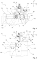
- Fig. 1 uses a perspective view to illustrate an exemplary design of a production plant, designated overall by 10, which has a machine tool 12.
- the machine tool 12 is basically designed as a machine suitable for milling and turning. In this way, the machine tool 12 is suitable for complete machining.
- the production plant 10 comprises the machine tool 10 and also a bar magazine 14 and a tool magazine 16. It goes without saying that appropriate handling technology can be provided for loading and/or changing tools. In this way, the production plant 10 can be operated autonomously, at least temporarily. Loading (usually with semi-finished products in the form of bars) and tool changing can be automated or partially automated. Unloading can also be automated or partially automated.
- a Cartesian coordinate system with axes X, Y, Z is indicated.
- the X-axis generally indicates a longitudinal direction or longitudinal extent.
- the Y-axis generally indicates a transverse direction or transverse extent.
- the Z-axis generally indicates a height direction or height extent (vertical extent).
- the X and Y axes are horizontal axes.
- the X and Y axes together form a horizontal plane.
- the Z axis is a vertical axis.
- Rotations about the Y axis are generally associated with a rotary B axis.
- Rotations around the Z axis are generally assigned to a rotary C axis.
- the coordinate system X, Y, Z as well as the other rotary axes/swivel axes A, B, C are used below in particular to illustrate embodiments and features and are not to be understood as limiting. The person skilled in the art can easily carry out any necessary transformations. This applies in particular with regard to the nomenclature for designating the axes of conventional lathes and conventional milling machines.
- the machine tool 12 comprises a frame 20, which in the embodiment according to Fig. 1 is surrounded by a housing 22 with at least one access opening.
- Fig. 2 shows an enlarged view of the production plant 10 in the same perspective orientation, with the housing 22 of the machine tool 12 hidden for illustrative purposes.
- the frame 20 of the machine tool 12 carries a kinematic system whose degrees of freedom and travel paths define a work space 26 in which workpieces can be machined.
- the frame 20 of the machine tool 12 rests on a substructure 28. This is possible primarily because the machine tool 12 is designed to be sufficiently compact. Therefore, further components and functional groups of the machine tool 12 can be arranged in the substructure 28. For a standing operator, however, a good overview and accessibility is provided due to the elevated arrangement of the frame 20 and the work space 26.
- FIG. 1 A perspective view is shown in each case.
- the machine tool 12 on its operator side.
- the operator stands, for example, offset in the Y direction in front of the work area 26 in order to have a good overview.
- the bar magazine 14 is coupled to the side of the machine tool 12 in order to provide and exchange bar material.
- 30 indicates a control of the machine tool 12 or the production plant 10.
- the control 30 is usually designed as an NC control or as a CNC control.
- the control 30 serves to control components of the machine tool 12 as well as other components and assemblies of the production plant 20 in the periphery of the Machine tool 12.
- the control 30 controls the axes and degrees of freedom of the machine tool 12.
- the control 30 is in Fig. 1 shown only symbolically.
- the controller 30 can be integrated into the machine tool 12. However, it is also conceivable to outsource tasks of the controller 30 at least partially to external units that are linked to the machine tool 12 or the production system 10 via data connections.
- CNC controllers are usually designed as programmable logic controllers (PLC).
- a tool spindle 34 is mounted on the frame 20 of the machine tool 12.
- the tool spindle 34 has a tool holder 36 in order to be able to drive a tool 38 held in the tool holder in rotation about a vertical longitudinal axis.
- the tool spindle 34 can be equipped with driven tools 38. This enables milling operations, drilling operations and the like.
- the machine tool 12 is equally suitable for both applications.
- the tool spindle 34 is designed as a vertically oriented, hanging spindle.
- the tool spindle 34 with the tool 38 can be moved translationally in three linear axes relative to the frame 20.
- the tool spindle 34 cannot be pivoted about a pivot axis (B axis) parallel to the Y axis.
- the tool spindle 34 can be moved translationally along an X-axis.
- an X-slide 42 is provided, which is mounted on an X-guide 44.
- a suitable drive is also installed.
- the tool spindle 34 can also be moved translationally along a Y-axis 50.
- a Y-slide 52 is provided, which is mounted on a Y-guide 54.
- a suitable drive is also installed.
- the X-axis 40 and the Y-axis 50 are oriented horizontally and orthogonally to one another.
- the tool spindle 34 can also be moved translationally along a Z-axis 60.
- a Z-slide 62 is provided, which is mounted on a Z-guide 64.
- a suitable drive is installed.
- the Y-guide 54 is formed on a flat bed 56 of the frame 20 of the machine tool 12.
- the Y-slide 52 is mounted on the frame 20 via the Y-guide 54.
- the Y-slide 52 has an inclined bed 58 which is inclined with respect to the Y axis and the Z axis.
- the X-guide 44 for the X-slide 42 is arranged on the inclined bed 58.
- the X-slide 42 is mounted on the Y-slide 52.
- the X-slide 42 has an end wall 66 which, in the exemplary embodiment, has a substantially vertical extension (parallel to the X-Z plane).
- the Z-guide 64 for the Z-slide 62 is arranged on the end wall 66.
- the kinematically closest axis is the Y-axis 50, followed by the X-axis 40, followed by the Z-axis 60.
- the Z-slide 62 is mounted on the X-slide 42
- the X-slide 42 is mounted on the Y-slide 52
- the Y-slide 52 is in turn mounted on the frame 20.
- the machine tool 12 further comprises a rotary spindle 68, which is part of a primary workpiece holding unit 70.
- the primary workpiece holding unit 70 is mounted on the frame 20.
- the primary workpiece holding unit 70 comprises a primary workpiece holder 72, which serves to hold and fix a workpiece, which is usually present as bar material.
- the primary workpiece holding unit 70 therefore has the functionality of a rotary spindle 68.
- the primary workpiece holding unit 70 is pivotably mounted on the frame 20 of the machine tool 12 via a pivot support 74.
- a pivot bearing 76 is provided, which enables the pivoting movement of the pivot support 74.
- the resulting swivel axis is indicated by a curved double arrow marked 78.
- the swivel axis 78 can also be referred to as the B1 axis (parallel to the Y axis).
- the machine tool 12 further comprises a secondary workpiece holding unit 80 which is mounted on the frame 20.
- the secondary workpiece holding unit 80 is designed, for example, as a gripper, rotary table and/or as a counter spindle.
- the primary Workpiece holding unit 70 and the secondary workpiece holding unit 80 are in the Figures 2 and 3 coaxially to each other, opposite each other and facing each other. In this way, the workpiece holding units 70, 80 can grip workpieces simultaneously, at least temporarily.
- the secondary workpiece holding unit 80 has a secondary workpiece holder 82.
- the secondary workpiece holding unit 80 is pivotally mounted on the frame 20 of the machine tool 12 via a pivot support 84.
- a pivot bearing 86 is provided which enables the pivoting movement of the pivot support 84.
- the resulting swivel axis is indicated by a curved double arrow marked 88.
- the swivel axis 88 can also be referred to as the B2 axis (parallel to the Y axis).
- the secondary workpiece holding unit 80 can be pivoted relative to the frame 20 about the pivot axis 88.
- the pivot bearing 86 is formed between the pivot support 84 and a pivot housing 90.
- the secondary workpiece holding unit 80 can also be moved translationally along the frame 20 along an X2 axis 92 in the X direction.
- the pivot housing 90 sits on an X-slide 94, which can be moved translationally along an X-guide 96. In this way, an X distance between the two pivot axes 78, 88 can be changed by moving the secondary workpiece holding unit 80 linearly relative to the primary workpiece holding unit 70. This movement can be used for machining purposes.
- the movement can also be used to move workpieces and/or semi-finished products translationally as part of the workpiece handling.
- the two pivot supports 74, 84 are cantilevered on the frame 20.
- the swivel supports 74, 84 are therefore not supported on both sides.
- the X-guide 96 is seated on a flat bed 98 formed on the frame 20.
- the X-guide 26 for the secondary workpiece holding unit 80 is seated on an upper side of the frame 20.
- the Y-guide 54 for the tool spindle 34 is seated on an upper side of the frame 20.
- the primary workpiece holding unit 70 is pivotable relative to the frame 20 about the pivot axis 78 (B1 axis).
- the secondary workpiece holding unit 80 is pivotable relative to the frame 20 about the Swivel axis 88 (B2 axis) can be swiveled and moved translationally along the linear X2 axis 92.
- the X2 axis 92 is horizontally oriented and coupled to a corresponding drive.
- the bar magazine 14 is also indicated.
- the bar magazine 14 is used to provide semi-finished products 100.
- the semi-finished products 100 are short bars.
- the semi-finished products 100 have a maximum length of 600 mm or a maximum of 500 mm.
- the bar magazine 14 is also connected to a Fig. 2
- the loading mechanism 102 is assigned to the loading mechanism 102, which is only shown symbolically.
- the loading mechanism 102 serves to introduce semi-finished products 100 into the working space 26 of the machine tool 12. This can be done by inserting a semi-finished product 100 into the rotary spindle 68 on the side facing away from the primary workpiece holder 72.
- the rotary spindle 68 is designed as a hollow spindle, the semi-finished product 100 can be pushed through the rotary spindle 68 in order to emerge at the opposite end at the primary workpiece holder 72 in the working space 26. This is the case with the Figures 2 and 3 shown horizontal orientation of the primary workpiece holding unit 70.
- a passage 104 is arranged, which is formed on/in a wall 106.
- the wall 106 extends vertically upwards from the base structure 28.
- the passage 104 allows semi-finished products 100 to be passed from the bar magazine 14 to the rotary spindle 68 for loading the machine tool 12.
- the primary workpiece holding unit 70 has a clamping unit 110 for holding and fixing workpieces.
- the rotary spindle 68 then allows a drive and/or a positioning of the workpieces by rotary movements about a longitudinal axis of the rotary spindle 68.
- the passage 104 comprises an actuating unit 112 which is designed to externally actuate the clamping unit 110 of the primary workpiece holding unit 70. This is only possible, for example, in the horizontal orientation of the workpiece holding unit 70 shown in Figures 2 and 3. In other words, the clamping unit 110 cannot necessarily be in a different Pivoting orientation of the workpiece holding unit 70.
- the external actuation of the clamping unit 110 by the actuating unit 112 has the advantage that the workpiece holding unit 70 with the primary workpiece holder 72 can be designed compactly.
- Loading the working space 26 requires, for example, a joint control of the loading mechanism 102 and the actuating unit 104 by the control 30 ( Fig. 1 ) when the primary workpiece holding unit 70 is in the horizontal orientation. If the secondary workpiece holding unit 80 is also involved, for example to pull a rod-like semi-finished product out of the primary workpiece holding unit 70 piece by piece in the X direction, this assembly is controlled accordingly by the controller 30. In some cases, this also requires a horizontal orientation of the secondary workpiece holding unit 80.
- Fig. 3 the secondary workpiece holder 82 of the secondary workpiece holding unit 80 is visible, which in the embodiment is provided with a clamping unit 118. In this way, workpieces 120 can be gripped and held.
- the horizontal, coaxial orientation of the primary workpiece holding unit 70 and the secondary workpiece holding unit 80 shown in FIG. 1 results in a common longitudinal axis 124.
- the rotary spindle 68 allows rotation of the workpiece 120 about the longitudinal axis 124, compare a curved double arrow designated 126 (also referred to as A-axis).
- A-axis also referred to as A-axis
- FIG. 4 illustrate the pivotability of the primary workpiece holding unit 80 (around the pivot axis 78) and the secondary workpiece holding unit 80 (around the pivot axis 88).
- Swiveled positions of the primary workpiece holding unit 70 and the secondary workpiece holding unit 80 are indicated by dashed lines.
- Swivel angles 130, 132 illustrate the extent of the swivel movement starting from the horizontal orientation, compare the horizontal swivel axis 124 (parallel to the X-axis).
- the secondary workpiece holding unit 80 is pivoted clockwise from its horizontal orientation.
- both workpiece holding units 70, 80 can be pivoted freely between a horizontal and a vertical orientation without the risk of collisions. A parallel pivoting movement of both workpiece holding units 70, 80 is therefore also possible.
- the respective maximum swivel range includes, for example, at least the horizontal and the vertical orientation, which leads to a swivel angle of 90° (angular degrees).
- the maximum swivel range then allows swivel movements of 10° beyond the horizontal orientation and the vertical orientation, resulting in a total maximum swivel angle of 110° (10°+90°+10°). This is not to be understood as limiting.
- machining in five axes is possible. If the secondary workpiece holding unit 80 also provides a rotation axis in addition to the swivel axis 88, machining in five axes is also possible there.
- Fig. 5 shows a transverse view of the machine tool 12, the viewing plane is perpendicular to the X direction.
- the design of the Y slide 52 with the inclined bed 58 results in an inclination 138 relative to the horizontal (Y direction).
- the inclined bed 58 allows a favorable and highly rigid mounting of the X slide 42 and the Z slide 62, to which the tool spindle 34 is fixed.
- the frame 20 of the machine tool 12 has a primary frame section 140 and a secondary frame section 142.
- the Y-guide 54 is arranged on an upper side (facing away from the base 28 (see also Fig. 6 ) of the primary frame section 140.
- the X-guide 96 for the pivot housing 90 of the secondary workpiece holding unit 80 is arranged on an upper side of the secondary frame section 142.
- the Y-guide 96 sits on the flat bed 98.
- the Y-guide 54 sits on the flat bed 56.
- the secondary frame section 142 is designed to be lower than the primary frame section 140. However, if the swivel housing 90 of the secondary workpiece holding unit 80 is mounted on the X-guide 96 of the secondary frame section 142, the overall height extension is approximately the same as the height extension of the primary frame section 140. This makes good use of the available installation space.
- Figures 5 and 6 show that the primary workpiece holding unit 70 is mounted on the primary frame section 140 and the secondary workpiece holding unit 80 is mounted on the secondary frame section 142.
- a recess 144 is provided in the frame 20 between the primary frame section 140 and the secondary frame section 142.
- a frame base extends between the primary frame section 140 and the secondary frame section 142.
- the recess 144 allows the primary workpiece holding unit 70 and the secondary workpiece holding unit 80 to be immersed during pivoting, see also the perspective view in Fig. 6 .
- the recess is open on three sides (two lateral sides and upwards). The installation space required by the machine tool 12 is used effectively. Workpieces can be completely machined on six sides as part of a complete machining process by turning and milling.
- the two swivel supports 74, 84 are arranged at least partially within the recess 114.
- the swivel support 74 is mounted in a floating manner on the primary frame section 140.
- the swivel support 84 is mounted in a floating manner on the secondary frame section 142.
- the pivot supports 74, 84 of the primary workpiece holding unit 70 and the secondary workpiece holding unit 80 are designed as identical parts.
- the pivot bearings 76, 86 of the primary workpiece holding unit 70 and the secondary workpiece holding unit 80 are also designed as identical parts. This leads to a smaller variety of parts and simplifies assembly, maintenance and repair.
- Fig. 6 also shows the external actuation unit 112, which is not covered by the primary workpiece holding unit 70 in the given pivoting orientation.
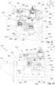
- FIG. 7-10 An example loading process with subsequent processing to produce a workpiece is illustrated using schematic views.
- the view orientation in the Figures 7-10 corresponds approximately to that of Fig. 4 .
- a state is shown in which the primary and secondary workpiece holding units 70, 80 are each in the horizontal orientation.
- a rod-shaped semi-finished product 100 can be introduced with the loading mechanism 102 through the passage 104 into the rotary spindle 68 designed as a hollow spindle 150.
- the semi-finished product 100 is, for example, a short rod with a length of 500 mm.
- the semi-finished product 100 can be introduced into the rotary spindle 68 at the rear of the rotary spindle 68, where no machining takes place, and guided through it.
- the clamping unit 110 is provided for clamping the semi-finished product 100, which in the exemplary embodiment can be actuated by the external actuating unit 112.
- the clamping unit 110 is, for example, a clamping unit 110 actuated by means of spring force, which can hold and fix the semi-finished product 100 automatically.
- the actuating unit 112 can act on the clamping unit 110, for example to relieve it (open it). In this way, the semi-finished product 100 can be introduced or advanced by a certain amount if several workpieces are to be produced on the basis of a semi-finished product 100.
- Fig. 8 illustrates a multi-axis machining operation in which the primary workpiece holding unit 70 is pivoted in order to make a front side 152 of the semi-finished product 100 accessible for the tool 38 of the tool spindle 34 on its primary workpiece holder 72.
- the machining operation can comprise turning and/or milling.
- the secondary workpiece holding unit 80 is not yet in engagement with the semi-finished product 100; this is not to be understood as limiting.
- Fig. 9 illustrates a state in which the primary workpiece holding unit 70 (for example, after the Fig. 8 illustrated processing) was brought back into the horizontal orientation.
- a workpiece 120 was produced on the basis of the semi-finished product 100.
- the workpiece 120 is not yet separated from the semi-finished product 100.
- the secondary workpiece holding unit 80 can now also be brought into the horizontal orientation by moving along the X2 axis in order to grasp the workpiece 120 with the secondary workpiece holder 82.
- the state shown can also be used to separate the workpiece 120 from the semi-finished product 100. This can also be done with a suitable tool 38 of the tool spindle 34.
- Fig. 10 illustrates a state in which the workpiece 120 has been separated from the remaining semi-finished product 100.
- the semi-finished product 100 remains in the primary workpiece holding unit 70, where a new workpiece can be produced. Furthermore, the workpiece 120, now held by the secondary workpiece holder 82, can be machined on its previously inaccessible side. This allows complete machining. In this way, the semi-finished product 100 can be machined piece by piece to produce a plurality of workpieces 120. After machining, the workpiece 120 can be released in a suitable manner from the secondary workpiece holding unit 80. This can be carried out with the aid of gravity or can involve a defined transfer to handling technology.
- the translational degree of freedom (compare the X2 axis 92) of the secondary workpiece holding unit 80 can also be used for the bar feed. This includes, for example, actuation of the internal clamping unit 110 of the primary workpiece holding unit 70 by the external actuation unit 112. In this way, a new section of the semi-finished product 100 can be made accessible for later processing. This is basically possible in the Fig. 9 shown orientation is conceivable. Thus, when a workpiece 120 has been released from the secondary workpiece holding unit 80, the secondary workpiece holding unit 80 can grip the now free end of the semi-finished product 100 at the primary workpiece holder 72 and pull it out of the primary workpiece holding unit 80 when the clamping unit 110 has been actuated accordingly. Alternatively can be found in Fig.
- the secondary workpiece holding unit 80 pulls the workpiece 120 and the semi-finished product 100 out of the primary workpiece holding unit 70 by movement along the X2 axis before the workpiece 120 is separated along the X2 axis in order to make sufficient material available for a new workpiece.
- FIG. 11 and 12 An exemplary design of a production plant is illustrated, which is designated as a whole with 210.
- the production plant 210 is the one already described on the basis of the Figures 1-10 illustrated production plant 10 is basically designed in a similar way. Therefore, the differences will be discussed below. Regarding the other detailed design, please refer to the explanations above.
- the production system 210 comprises a machine tool 212, which is assigned a bar magazine 214.
- the machine tool 212 comprises a frame 220, which rests on a substructure 228.
- the machine tool 212 comprises kinematics that basically correspond to those of the machine tool 12.
- a tool spindle 234 can be moved in three translational axes (X, Y, Z) relative to the frame 220 in order to machine workpieces.
- the tool spindle 234 cannot be pivoted, in particular no B-axis (pivoting movements about the Y-axis) is provided for the tool spindle 234.
- An X-slide 242, a Y-slide 252 and a Z-slide 262 are provided for the translational movement of the tool spindle 234.
- the Y-slide 252 is mounted on the frame 220 and can be moved relative to it in the Y direction.
- the X-slide 242 is mounted on the Y-slide 252 and can be moved relative to it in the X direction.
- the Z-slide is mounted on the X-slide 242 and can be moved relative to it in the Z direction.
- the tool spindle 234 is mounted on the Z-slide 262 and can be moved together with it.
- the machine tool further comprises a primary workpiece holding unit 270 and a secondary workpiece holding unit 280, each of which is
- the secondary workpiece holding unit 280 is also mounted in a swivel housing 290 which is mounted on the frame 220 via an X-slide 294 and can be moved relative to the frame in the X direction.
- the primary workpiece holding unit 270 is also pivotally mounted in a pivot housing 298.
- the pivot housing 290 for the secondary workpiece holding unit 280 and the pivot housing 298 for the primary workpiece holding unit 270 are designed as identical parts.
- FIG. 12 clarifies that the swivel housing 298 for the primary workpiece holding unit 270 is arranged in a frame opening 300 in the exemplary embodiment.
- the swivel housings 290, 298 can be designed as identical parts.
- a passage 304 is arranged between the bar magazine 214 and the primary workpiece holding unit 270, through which the machine tool 212 can be loaded with the bar material.
- the frame opening 300 extends in the Y direction through the primary frame section 340.
- two cheeks 360, 362 are formed on the frame 220, between which the frame opening 300 is arranged.
- the two cheeks 360, 362 are offset relative to one another in the X direction.
- the two cheeks define a guide distance for guiding the Y-slide 252 in the Y direction.
- the rear view according to Fig. 12 shows that the frame opening 300 can be used to accommodate the swivel housing 298, that on the other hand, however, it is also conceivable that it can be used for other purposes. This could be, for example, transfer purposes, such as for unloading processed workpieces and/or for changing tools. This is not to be understood as restrictive.
- FIG. 13 and 14 An exemplary design of a production plant 410 with a machine tool 412 is illustrated.
- the production plant 410 is already described in the Figures 1-12
- the production plants 10 and 210 illustrated are basically designed in a similar way. The following will therefore primarily focus on differences. For the remaining detailed design, please refer to the explanations above.
- the production plant 410 (see Fig. 14 ) comprises a machine tool 412 and a bar magazine 414 for providing workpieces, compare also the passage 504 between the bar magazine 414 and the machine tool 412. Loading with workpieces is therefore possible analogously to the designs already described.
- the machine tool 412 rests on a frame 420.
- Fig. 14 it is indicated that the frame 420 rests on a substructure 428.
- the frame 420 is designed as a stand 422.
- the machine tool 412 comprises a tool spindle 434, the kinematics of which in the exemplary embodiment corresponds to that of the tool spindles 34, 234.
- the tool spindle 434 can be moved in three translational axes (X, Y, Z).
- X movement an X-slide 442 is provided, which can be moved along an X-guide 444.
- a Y-slide 452 is provided, which can be moved along a Y-guide 454.
- a Z-slide 462 is provided, which can be moved along a Z-guide 464.
- the Y-guide 454 is formed on a flat bed 456 of the frame 420.
- the X-guide 444 is formed on the Y-slide 452, for example on an inclined bed of the Y-slide 452.
- the Z-guide 464 is formed on the Y-slide 442, for example on an end wall of the Y-slide 442.
- the machine tool 412 comprises a primary workpiece holding unit 470 and a secondary workpiece holding unit 480, each of which can be pivoted about a pivot axis parallel to the Y direction.
- the primary workpiece holding unit 470 comprises a primary workpiece holder 472.
- the primary workpiece holding unit 470 is pivotally mounted on the frame 420 via a primary pivot support 474 and a primary pivot bearing 476.
- the secondary workpiece holding unit 480 comprises a secondary workpiece holder 482.
- the secondary workpiece holding unit 480 is pivotally mounted on the frame 420 via a secondary pivot support 484 and a secondary pivot bearing 486.
- a pivot housing 490 for the secondary workpiece holding unit 480 is also shown.
- the pivot housing 490 houses the secondary pivot bearing 486 and a corresponding pivot drive.
- the secondary workpiece holding unit 480 can be moved translationally along a linear axis 492.
- the linear axis 492 can also be referred to as the X2 axis.
- the secondary workpiece holding unit 480 is mounted on an X-slide 494, which can be moved translationally along an X-guide 496.
- the X-guide 496 is formed on a flat bed 498 of the frame 420.
- the frame 420 therefore has a flat bed 456 for the Y-guide 454 at its upper end and a flat bed 498 for the X-guide 496 offset vertically (downwards) from this.
- both flat beds 456, 498 use the same installation space in the X-direction and the Y-direction. Overall, this ensures a small space requirement and a small footprint of the frame 420.
- the secondary workpiece holding unit 480 is mounted in a frame opening 500 in the frame 420.
- the frame 420 has a front wall 502 facing the work area.
- the front wall 502 has at least partially or predominantly a vertical extension.
- the primary workpiece holder 472 and the secondary workpiece holder 482 are arranged in front of the front wall 502.
- the primary pivot support 474 and the secondary pivot support 484 extend through the front wall 502 starting from the stand 422 of the frame 420.
- the frame opening 500 includes a Y-recess 506 and an X-recess 508.
- the Y-recess 506 may also be referred to as a central recess.
- the X-recess 508 may also be referred to as a side recess.
- the Y-recess 506 completely penetrates the frame 420 in the Y-direction.
- the X-recess 508 partially penetrates the frame 420 in the X-direction to make the Y-recess 506 accessible in the X-direction.
- the X-guide 496 is arranged on an underside of the frame opening 500, in particular the Y-recess 506.
- the pivot housing 490 can thus be moved within the frame opening 500 along the linear axis 492.
- the Y-recess 506 is arranged between a first cheek 560 and a second cheek 562 of the frame 420.
- a cross member 510 also extends between the first cheek 560 and the second cheek 562 on the upper side of the frame 420 facing the Y-slide 452. In this way, the Y-recess 506 is in the viewing orientation according to Fig. 14 enclosed on four sides.
- the X-recess 508 extends through the cheek 562 in the direction of the Y-recess 506. This provides lateral access to the Y-recess 506.
- the X-recess 508 can, for example, accommodate a drive 516 for the translational movement of the secondary workpiece holding unit 480 along the linear axis 492. In this way, the translational degree of freedom of the secondary workpiece holding unit 480 can be conveniently integrated into the frame 420 designed in a column construction.
- the frame 420 is compact and at the same time rigid.
- FIG. 15 An exemplary embodiment of a method for machining bar stock is illustrated using a schematic, highly simplified block diagram.
- the method starts at a step S10 and ends at a step S28.
- the method can be carried out using a machine tool or production system according to at least one of the embodiments described herein.
- a semi-finished product is provided, which is in particular rod material.
- these are so-called short rods, with different cross-sections (round, non-round, polygonal design, hollow profiles) being conceivable.
- the short rods have a maximum length of 600 mm or a maximum of 500 mm.
- step S14 in which the primary workpiece holding unit is moved into an orientation suitable for receiving the semi-finished product if the suitable orientation is not already present.
- This can include a pivoting movement in the direction of a horizontal orientation.
- the machine tool is loaded by introducing the semi-finished product into the primary workpiece holding unit.
- This can include inserting the semi-finished product into a primary workpiece holding unit designed as a hollow spindle.
- Step S16 can also include actuating a clamping unit integrated into the primary workpiece holding unit by an external actuating unit.
- the semi-finished product can be machined to form a workpiece.
- the machining can take place as turning and/or milling.
- the semi-finished product can be machined on five sides.
- a step S20 the workpiece is held with the secondary workpiece holding unit. This can at least temporarily result in a joint holding of the semi-finished product with the workpiece by the primary workpiece holding unit and the secondary workpiece holding unit. In such a state, machining of the workpiece is also conceivable. Gripping and holding the workpiece with the secondary workpiece holding unit allows the workpiece to be released from the primary workpiece holding unit (separated from the bar material).
- a step S22 the workpiece is separated from the semi-finished product in a state in which the primary workpiece holding unit and the secondary workpiece holding unit hold the workpiece together.
- the workpiece can then be machined on the previously inaccessible side while it is held by the secondary workpiece holding unit.
- unloading can follow. This can include a defined release of the workpiece from the second workpiece holding unit. For example, this can include a handover to handling technology. If necessary, a gravity-assisted release is also conceivable, in which the workpiece is dropped from the secondary workpiece holding unit.
- the primary workpiece holding unit and the secondary workpiece holding unit can also work together to ensure a controlled feeding of the semi-finished product.
- a feed allows a plurality of workpieces to be produced in succession on the basis of a single semi-finished product in the form of bar stock.
- the secondary workpiece holding unit can be moved in translation relative to the frame of the machine tool. In this way, the secondary workpiece holding unit can pull the semi-finished product out of the primary workpiece holding unit when the clamping unit of the primary workpiece holding unit is released, for example as a result of an actuation with the external actuation unit.
- the primary workpiece holding unit and the secondary workpiece holding unit each have a swivel axis in the form of a B-axis.
- the primary workpiece holding unit and the secondary workpiece holding unit can jointly grip the semi-finished product/workpiece. Since at least the primary workpiece holding unit is designed as a turning spindle, turning is possible in this configuration.
- the common coaxial Orientation can also be used for transfer purposes.
- the tool spindle does not have to be equipped with a swivel axis. Nevertheless, machining in five axes is still possible. By using the swivel axes of the primary workpiece holding unit and the secondary workpiece holding unit, six-sided machining is possible, and workpieces can be completely machined.
Landscapes
- Engineering & Computer Science (AREA)
- Mechanical Engineering (AREA)
- Machine Tool Units (AREA)
- Turning (AREA)
Applications Claiming Priority (1)
| Application Number | Priority Date | Filing Date | Title |
|---|---|---|---|
| DE102023120440.8A DE102023120440A1 (de) | 2023-08-01 | 2023-08-01 | Werkzeugmaschine und Verfahren zur Bearbeitung von Stangenmaterial |
Publications (2)
| Publication Number | Publication Date |
|---|---|
| EP4501533A2 true EP4501533A2 (fr) | 2025-02-05 |
| EP4501533A3 EP4501533A3 (fr) | 2025-04-16 |
Family
ID=92108304
Family Applications (1)
| Application Number | Title | Priority Date | Filing Date |
|---|---|---|---|
| EP24191479.5A Pending EP4501533A3 (fr) | 2023-08-01 | 2024-07-29 | Machine-outil, installation de fabrication et procédé d'usinage de matériau en barre |
Country Status (2)
| Country | Link |
|---|---|
| EP (1) | EP4501533A3 (fr) |
| DE (1) | DE102023120440A1 (fr) |
Citations (2)
| Publication number | Priority date | Publication date | Assignee | Title |
|---|---|---|---|---|
| EP1818136A1 (fr) | 2006-02-13 | 2007-08-15 | Stama Maschinenfabrik Gmbh | Machine-outil et procédé destiné au traitement par enlèvement de copeaux de pièces usinées, en particulier de pièces usinées métalliques |
| DE102010019762A1 (de) | 2009-05-08 | 2010-11-11 | Mori Seiki Co., Ltd., Yamatokoriyama | Werkzeugmaschine für Dreharbeit |
Family Cites Families (6)
| Publication number | Priority date | Publication date | Assignee | Title |
|---|---|---|---|---|
| DE4228708C2 (de) * | 1992-08-28 | 1995-02-23 | Chiron Werke Gmbh | Numerisch gesteuertes Bearbeitungszentrum |
| JP2788231B2 (ja) * | 1996-09-04 | 1998-08-20 | 川崎重工業株式会社 | 長尺バー材加工装置とその加工方法 |
| DE102006013418B4 (de) * | 2006-03-14 | 2016-11-10 | Stama Maschinenfabrik Gmbh | Werkzeugmaschine zur spanabhebenden Bearbeitung von Werkstücken, insbesondere von metallischen Werkstücken |
| CN106514282A (zh) * | 2016-12-28 | 2017-03-22 | 深圳市创新精艺科技有限公司 | 直线电机驱动的数控机床 |
| US20210078120A1 (en) * | 2017-09-13 | 2021-03-18 | Makino Milling Machine Co., Ltd. | Machine tool |
| DE102021113890A1 (de) * | 2021-05-28 | 2022-12-01 | Chiron Group Se | Fertigungssystem und Anlage zur spanenden Fertigung |
-
2023
- 2023-08-01 DE DE102023120440.8A patent/DE102023120440A1/de active Pending
-
2024
- 2024-07-29 EP EP24191479.5A patent/EP4501533A3/fr active Pending
Patent Citations (2)
| Publication number | Priority date | Publication date | Assignee | Title |
|---|---|---|---|---|
| EP1818136A1 (fr) | 2006-02-13 | 2007-08-15 | Stama Maschinenfabrik Gmbh | Machine-outil et procédé destiné au traitement par enlèvement de copeaux de pièces usinées, en particulier de pièces usinées métalliques |
| DE102010019762A1 (de) | 2009-05-08 | 2010-11-11 | Mori Seiki Co., Ltd., Yamatokoriyama | Werkzeugmaschine für Dreharbeit |
Also Published As
| Publication number | Publication date |
|---|---|
| EP4501533A3 (fr) | 2025-04-16 |
| DE102023120440A1 (de) | 2025-02-06 |
Similar Documents
| Publication | Publication Date | Title |
|---|---|---|
| EP0737544B1 (fr) | Machine-outil avec plusieurs broches | |
| EP3027358B1 (fr) | Machine-outil comprenant plusieurs ensembles de broches multibroches | |
| EP1733840B1 (fr) | Système de machine-outil avec un robot et un magazin pour outils | |
| EP1765550B1 (fr) | Machine-outil | |
| EP3535092B1 (fr) | Machine de pierrage avec une pluralité de postes de travail | |
| EP1871570B1 (fr) | Châine de production servant à usiner des pièces avec souplesse | |
| DE102013012633A1 (de) | Werkzeugmaschine mit einer Werkstückwechseleinrichtung | |
| DE9321647U1 (de) | Aus Baugruppen zusammengesetzte Bearbeitungszelle | |
| EP1118428B2 (fr) | Tour | |
| DE102009009969B4 (de) | Werkzeugmaschine | |
| EP4094885A1 (fr) | Dispositif combiné de transfert et de stockage, ainsi qu'installation d'usinage par enlèvement des copeaux | |
| DE102021113890A1 (de) | Fertigungssystem und Anlage zur spanenden Fertigung | |
| EP1927429A1 (fr) | Machine-outil avec magasin à outils | |
| EP1807242A1 (fr) | Machine-outil tres flexible comprenant plusieurs supports de piece | |
| EP1752255A2 (fr) | Tour multibroche avec manipulateur de pièces articulé | |
| EP1511596A1 (fr) | Tour multibroche | |
| EP2139641B1 (fr) | Dispositif de changement d'outil | |
| EP3159102B1 (fr) | Machine-outil avec dispositif de commande et procédé pour machine-outil | |
| EP1281475A2 (fr) | Machine-outil avec deux broches pour pièces de travail et deux supports d'outils | |
| EP4501533A2 (fr) | Machine-outil, installation de fabrication et procédé d'usinage de matériau en barre | |
| WO2017220339A1 (fr) | Centre de traitement multifonctionnel | |
| WO2017050835A2 (fr) | Machine-outil | |
| DE102017127116B4 (de) | Werkzeugmaschine, Fertigungszelle sowie Verfahren zum Betreiben einer Fertigungszelle | |
| DE19607883A1 (de) | Vertikal-Drehmaschine | |
| DE29825149U1 (de) | Werkzeugmaschine mit Werkstückwechseleinrichtung |
Legal Events
| Date | Code | Title | Description |
|---|---|---|---|
| PUAI | Public reference made under article 153(3) epc to a published international application that has entered the european phase |
Free format text: ORIGINAL CODE: 0009012 |
|
| STAA | Information on the status of an ep patent application or granted ep patent |
Free format text: STATUS: THE APPLICATION HAS BEEN PUBLISHED |
|
| AK | Designated contracting states |
Kind code of ref document: A2 Designated state(s): AL AT BE BG CH CY CZ DE DK EE ES FI FR GB GR HR HU IE IS IT LI LT LU LV MC ME MK MT NL NO PL PT RO RS SE SI SK SM TR |
|
| PUAL | Search report despatched |
Free format text: ORIGINAL CODE: 0009013 |
|
| AK | Designated contracting states |
Kind code of ref document: A3 Designated state(s): AL AT BE BG CH CY CZ DE DK EE ES FI FR GB GR HR HU IE IS IT LI LT LU LV MC ME MK MT NL NO PL PT RO RS SE SI SK SM TR |
|
| RIC1 | Information provided on ipc code assigned before grant |
Ipc: B23Q 1/62 20060101ALI20250313BHEP Ipc: B23Q 1/54 20060101ALI20250313BHEP Ipc: B23Q 1/52 20060101ALI20250313BHEP Ipc: B23Q 1/01 20060101AFI20250313BHEP |
|
| STAA | Information on the status of an ep patent application or granted ep patent |
Free format text: STATUS: REQUEST FOR EXAMINATION WAS MADE |
|
| 17P | Request for examination filed |
Effective date: 20251015 |