EP4094910A1 - Procédé d'usinage d'une pièce tabulaire, ainsi que dispositif d'usinage - Google Patents
Procédé d'usinage d'une pièce tabulaire, ainsi que dispositif d'usinage Download PDFInfo
- Publication number
- EP4094910A1 EP4094910A1 EP22175089.6A EP22175089A EP4094910A1 EP 4094910 A1 EP4094910 A1 EP 4094910A1 EP 22175089 A EP22175089 A EP 22175089A EP 4094910 A1 EP4094910 A1 EP 4094910A1
- Authority
- EP
- European Patent Office
- Prior art keywords
- workpiece
- machining
- milling cutter
- processing device
- edge
- Prior art date
- Legal status (The legal status is an assumption and is not a legal conclusion. Google has not performed a legal analysis and makes no representation as to the accuracy of the status listed.)
- Pending
Links
- 238000000034 method Methods 0.000 title claims abstract description 28
- 238000003754 machining Methods 0.000 title claims description 35
- 238000012545 processing Methods 0.000 claims abstract description 62
- 238000003801 milling Methods 0.000 claims description 35
- 239000000463 material Substances 0.000 claims description 12
- 239000000523 sample Substances 0.000 claims description 10
- 239000011248 coating agent Substances 0.000 claims description 8
- 238000000576 coating method Methods 0.000 claims description 8
- 239000002023 wood Substances 0.000 claims description 6
- 230000001360 synchronised effect Effects 0.000 claims description 3
- 238000001514 detection method Methods 0.000 claims description 2
- 238000004519 manufacturing process Methods 0.000 description 4
- 230000008569 process Effects 0.000 description 4
- 238000012805 post-processing Methods 0.000 description 3
- 230000008901 benefit Effects 0.000 description 2
- 239000000700 radioactive tracer Substances 0.000 description 2
- 230000000284 resting effect Effects 0.000 description 2
- 230000004888 barrier function Effects 0.000 description 1
- 230000001419 dependent effect Effects 0.000 description 1
- 239000000428 dust Substances 0.000 description 1
- 230000004048 modification Effects 0.000 description 1
- 238000012986 modification Methods 0.000 description 1
- 230000002441 reversible effect Effects 0.000 description 1
- 230000007704 transition Effects 0.000 description 1
Images


Classifications
-
- B—PERFORMING OPERATIONS; TRANSPORTING
- B27—WORKING OR PRESERVING WOOD OR SIMILAR MATERIAL; NAILING OR STAPLING MACHINES IN GENERAL
- B27C—PLANING, DRILLING, MILLING, TURNING OR UNIVERSAL MACHINES FOR WOOD OR SIMILAR MATERIAL
- B27C5/00—Machines designed for producing special profiles or shaped work, e.g. by rotary cutters; Equipment therefor
- B27C5/003—Machines designed for producing special profiles or shaped work, e.g. by rotary cutters; Equipment therefor copy milling
-
- B—PERFORMING OPERATIONS; TRANSPORTING
- B27—WORKING OR PRESERVING WOOD OR SIMILAR MATERIAL; NAILING OR STAPLING MACHINES IN GENERAL
- B27D—WORKING VENEER OR PLYWOOD
- B27D5/00—Other working of veneer or plywood specially adapted to veneer or plywood
- B27D5/006—Trimming, chamfering or bevelling edgings, e.g. lists
Definitions
- the invention relates to a method for processing a panel-shaped workpiece and a processing device for processing a panel-shaped workpiece.
- a method for processing a panel-shaped workpiece and a processing device for processing a panel-shaped workpiece.
- Such a method and such a processing device are used in particular in the field of the woodworking and processing industry.
- the invention is based on the object of providing a method for machining a plate-shaped workpiece and a machining device for machining a plate-shaped workpiece, with which the effort involved in post-processing can be reduced.
- a method according to the invention comprises the features according to claim 1. Further preferred embodiments are listed in the dependent claims. Furthermore, the invention provides a processing device, wherein the processing device or aspects thereof can be used within the framework of the method.
- a method for machining a plate-shaped workpiece using a machining device comprising the steps: detecting a workpiece, preferably a workpiece edge, in particular a workpiece front edge or a workpiece rear edge of the workpiece, applying the probe element to a main side of the workpiece, carrying out a first machining operation with the milling cutter while the probe element is moved over a workpiece edge, applying the probe element on an impact side, in particular an impact lower edge or impact upper side, and carrying out a second processing with the milling cutter while the probe element is moved over another workpiece edge.
- workpieces can be produced with consistent quality, which have a high quality due to a corresponding look and feel.
- the "main workpiece side” is (when the workpiece is horizontally oriented) a vertically upper or lower side of the workpiece.
- a “workpiece main side” is also referred to as a broad side in the case of plate-shaped workpieces.
- a “narrow workpiece side” or also several “narrow workpiece sides” are located between the main workpiece sides.
- a "workpiece edge” is a transition area between sides of a workpiece, for example between a workpiece main side and a workpiece edge.
- An "impact side” is a side of an overhang or protrusion of the workpiece located between narrow sides of the workpiece.
- the cuff side can be provided as a cuff bottom side or a cuff top side.
- the impact side is aligned parallel to a main side of the workpiece.
- an imaginary plane formed by the impact side can also intersect an imaginary plane formed by the main side of the workpiece.
- the workpiece is moved in the course of the method and the processing device is synchronized to a movement of the workpiece. This ensures high productivity.
- the probe element is lifted off the workpiece after the first machining has been carried out. In this way, damage to the workpiece can be avoided. Provision is also made for the processing device to be moved away from the workpiece after the second processing has been carried out, so that the processing device can be moved to a starting position.
- the length of the milling cutter is ⁇ 50 mm, in particular ⁇ 35 mm, so that different workpiece types can be machined without damage.
- the milling cutter is cylindrical, preferably without a radius.
- the milling cutter has a diameter of ⁇ 20 mm, in particular ⁇ 15 mm, so that comparatively delicate machining processes can be carried out.
- the milling cutter is an end mill.
- impact side is aligned parallel to the main side of the workpiece.
- Such a configuration can be a door rabbet of a panel-shaped workpiece.
- the workpiece is made of wood or wood-based materials and is provided with a coating material at least on the main side of the workpiece and on the impact side.
- a workpiece can be a door leaf.
- steps of applying and carrying out the first and second processing can be carried out on a second workpiece edge, in particular a workpiece front edge or a workpiece rear edge. This can be done, for example, in one pass through the workpiece.
- the invention relates to a processing device for processing a plate-shaped workpiece.
- the processing device includes: a particular cylindrical milling cutter, and at least one probe element, the diameter of which is equal to or greater than a processing diameter of the milling cutter. In this way, a targeted processing of an overhang of the coating material is achieved, with further sections of the workpiece being protected.
- the milling cutter and the probe element are arranged coaxially or can be positioned coaxially.
- Such a processing device can have a control device in order to carry out the method described above.
- the processing device can comprise at least two feeler elements, each of which can be moved from a working position to a resting position. Thus, both the front edge of the workpiece and the rear edge of the workpiece can be machined with the machining device.
- the milling cutter has a diameter of ⁇ 20 mm, preferably ⁇ 15 mm. Comparatively delicate machining processes can thus be carried out.
- the milling cutter is an end mill.
- the milling cutter has a length of ⁇ 50 mm, in particular ⁇ 35 mm, so that different workpiece types can be machined without damage.
- the milling cutter is cylindrical, preferably without a radius.
- the at least one feeler element can be a feeler roller.
- a feeler roller can roll off the workpiece without causing any damage and thereby guide the milling cutter to carry out machining operations. It is preferable that the tracer is located beyond an end portion of the milling cutter. Thus, the guidance of the milling cutter takes place as it were at or beyond the tip of the milling cutter.
- no further contact surface serving as a stop for positioning is assigned to the milling cutter.
- a contact surface is usually provided in sections around the milling cutter in order to provide a constant distance between the milling cutter and the workpiece to be machined during machining. Such a contact surface can be omitted according to this embodiment.
- the Processing device 1 shows a side view of an embodiment of a processing device 1 according to the invention.
- the Processing device 1 includes a processing unit 20 which is accommodated on a carrier 2 of the processing device 1 .
- the processing device 1 is intended in particular for processing workpieces made of wood or wood-based materials, in particular panel-shaped workpieces with several narrow surfaces. Such workpieces are processed in throughput.
- the carrier 2 of the processing device 1 can be moved in a feed direction V via a guide device.
- the machining device 1 can be moved along the feed direction V, in which a workpiece is also moved by means of a conveyor device (not shown), in order to carry out machining processes on the workpiece W while the workpiece is moving.
- a suction hose 5 connected to the processing unit 20 is also provided on the carrier 2 . Processing residues, such as chips or dust, can be removed from a processing area of the processing unit 20 with the suction hose 5 .
- the machining unit 20 includes an end mill 21 which has a cylindrical shape and a comparatively small diameter. Since the end mill 21 does not have a radius, but is cylindrical, no rounded workpiece edge is introduced during processing with the end mill 21, but rather the end mill, as explained below, is guided over a workpiece edge in order to mill off excess material.
- the configuration of the end mill 21 makes it possible to rework a workpiece edge, and in particular a corner region in the case of a door rebate edge, without colliding with other sections of the workpiece W in the process.
- the milling cutter 21 is guided only by a feeler device. A further contact surface, in particular one as a stop for positioning the milling cutter 21, is not provided.
- the processing device 1 includes a first feeler device 30, which can be moved from a working position to a rest position (and vice versa).
- the feeler device 30 comprises a base 31, a feeler roller carrier element 32 and a feeler roller 33 mounted on the feeler roller carrier element 32 (probe element).
- the base 31 is movable along a rail 34 .
- a first drive 35 is provided to provide movement of the base 31, and hence the elements carried by the base 31, a first drive 35 is provided.
- the feeler roller 33 has a diameter that is equal to or larger than a machining diameter of the milling cutter 21 . In this way, a targeted processing of an overhang of the coating material is achieved without damaging other sections of the workpiece.
- the second feeler device 40 comprises a base 41, a feeler roller carrier element 42 and a feeler roller 43 (sensing element) mounted therein.
- the base 41 is movable along a rail 44, the movement being initiated by a second drive 45.
- the second sensing device 40 can be moved from a working position to a resting position (and vice versa).
- the feeler roller 43 has, like the feeler roller 33, a diameter which is equal to or greater than a machining diameter of the milling cutter 21.
- the processing device 1 is in a waiting position below a workpiece W, the workpiece W being moved by means of a conveying device (not shown), for example a transport belt. If the workpiece W is detected by means of a light barrier (detection device), the processing device 1 is started by means of a line control shortly after the front edge of the workpiece has passed the processing unit 20 . In the course of this, the processing device 1 is synchronized to the movement of the workpiece W and moves with the workpiece W during the steps described below.
- a conveying device not shown
- the processing device 1 is started by means of a line control shortly after the front edge of the workpiece has passed the processing unit 20 .
- the processing device 1 is synchronized to the movement of the workpiece W and moves with the workpiece W during the steps described below.
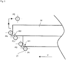
- the processing device 1 is moved in such a way that the processing device 1 is path-controlled and places the feeler roller 33 on the underside of the workpiece (one of the main sides of the workpiece) (position P1).
- the end mill 21 extends in the same axial direction as the feeler roller 33.
- a corner region of the workpiece W is then machined with the end mill 21 by moving the tracer roller 33 over a radius of a workpiece edge W1 (movement to position P2).
- the processing device 1 then accelerates away from the workpiece W with the feeler roller 33 and the end mill 21 and rests against the overhanging underside (position P3).
- the end mill 21 now removes the excess edge at this corner area of the workpiece W by guiding the feeler roller 33 over a radius of another workpiece edge W2 (movement in the direction of position P4).
- the processing device 1 is now accelerated away from the workpiece W, so that the feeler roller 33 and the end mill 21 are positioned above (or, according to a modification, to the side) of the workpiece W (position P5). After the workpiece W has passed the processing device 1, the processing device 1 is returned to the starting position so that a subsequent workpiece can be processed.
- a process sequence for machining a workpiece trailing edge can take place in reverse order, with the machining device 1 following the workpiece W. Both when machining the front edge of the workpiece ( figure 3 ) as well as the rear edge of the workpiece, the process can also take place vertically, from top to bottom.
Landscapes
- Life Sciences & Earth Sciences (AREA)
- Engineering & Computer Science (AREA)
- Mechanical Engineering (AREA)
- Wood Science & Technology (AREA)
- Forests & Forestry (AREA)
- Milling Processes (AREA)
Applications Claiming Priority (1)
| Application Number | Priority Date | Filing Date | Title |
|---|---|---|---|
| DE102021113528.1A DE102021113528A1 (de) | 2021-05-26 | 2021-05-26 | Verfahren zum Bearbeiten eines plattenförmigen Werkstücks sowie Bearbeitungseinrichtung |
Publications (1)
| Publication Number | Publication Date |
|---|---|
| EP4094910A1 true EP4094910A1 (fr) | 2022-11-30 |
Family
ID=81846552
Family Applications (1)
| Application Number | Title | Priority Date | Filing Date |
|---|---|---|---|
| EP22175089.6A Pending EP4094910A1 (fr) | 2021-05-26 | 2022-05-24 | Procédé d'usinage d'une pièce tabulaire, ainsi que dispositif d'usinage |
Country Status (3)
| Country | Link |
|---|---|
| EP (1) | EP4094910A1 (fr) |
| CN (1) | CN115401748A (fr) |
| DE (1) | DE102021113528A1 (fr) |
Cited By (1)
| Publication number | Priority date | Publication date | Assignee | Title |
|---|---|---|---|---|
| DE102022134920B3 (de) * | 2022-11-01 | 2024-03-21 | Oav Equipment And Tools, Inc. | Kantenbandschneidvorrichtung einer kantenanleimmaschine |
Citations (8)
| Publication number | Priority date | Publication date | Assignee | Title |
|---|---|---|---|---|
| US4787786A (en) * | 1987-08-24 | 1988-11-29 | Freud Ivan B | Laminate cutting device |
| DE4243054C1 (de) * | 1992-12-18 | 1994-07-14 | Homag Maschinenbau Ag | Vorrichtung zur Bearbeitung der Kantenränder von fortlaufend bewegten plattenförmigen Werkstücken |
| DE19644137A1 (de) * | 1996-10-23 | 1998-04-30 | Reich Spezialmaschinen Gmbh | Fräsaggregat |
| DE10039413A1 (de) * | 2000-08-11 | 2002-03-28 | Homag Maschinenbau Ag | Bearbeitungsaggregat für ein Bearbeitungszentrum |
| EP1229412A2 (fr) * | 2001-01-31 | 2002-08-07 | SORBINI S.r.l. | Machine pour travailler les bords d'un panneau |
| DE102006034437B3 (de) * | 2006-07-26 | 2007-12-27 | Ima Klessmann Gmbh Holzbearbeitungssysteme | Durchlauf-Holzbearbeitungsmaschine mit Besäum-Aggregat |
| DE102008018079A1 (de) * | 2008-04-09 | 2009-10-15 | Zimmer, Günther | Fräsaggregat mit pendelnder Werkzeugaufnahmespindel |
| EP3800021A1 (fr) * | 2019-10-02 | 2021-04-07 | HOMAG GmbH | Affleureuse, système de travail du bois doté d'une affleureuse ainsi qu'un procédé de travail de pièces en forme de panneau |
Family Cites Families (3)
| Publication number | Priority date | Publication date | Assignee | Title |
|---|---|---|---|---|
| DE102010064473B3 (de) * | 2010-06-11 | 2017-05-18 | Ima Klessmann Gmbh Holzbearbeitungssysteme | Verfahren und Bearbeitungsaggregat zum Bündigfräsen und/oder Abziehen eines Kantenbandes |
| CN104275722A (zh) * | 2014-08-05 | 2015-01-14 | 郑维劲 | 新型木工双面仿形镂铣床 |
| CN206445903U (zh) * | 2017-01-07 | 2017-08-29 | 王防震 | 一种木工回转同轴双臂仿形铣边机 |
-
2021
- 2021-05-26 DE DE102021113528.1A patent/DE102021113528A1/de active Pending
-
2022
- 2022-05-24 EP EP22175089.6A patent/EP4094910A1/fr active Pending
- 2022-05-24 CN CN202210568063.1A patent/CN115401748A/zh active Pending
Patent Citations (8)
| Publication number | Priority date | Publication date | Assignee | Title |
|---|---|---|---|---|
| US4787786A (en) * | 1987-08-24 | 1988-11-29 | Freud Ivan B | Laminate cutting device |
| DE4243054C1 (de) * | 1992-12-18 | 1994-07-14 | Homag Maschinenbau Ag | Vorrichtung zur Bearbeitung der Kantenränder von fortlaufend bewegten plattenförmigen Werkstücken |
| DE19644137A1 (de) * | 1996-10-23 | 1998-04-30 | Reich Spezialmaschinen Gmbh | Fräsaggregat |
| DE10039413A1 (de) * | 2000-08-11 | 2002-03-28 | Homag Maschinenbau Ag | Bearbeitungsaggregat für ein Bearbeitungszentrum |
| EP1229412A2 (fr) * | 2001-01-31 | 2002-08-07 | SORBINI S.r.l. | Machine pour travailler les bords d'un panneau |
| DE102006034437B3 (de) * | 2006-07-26 | 2007-12-27 | Ima Klessmann Gmbh Holzbearbeitungssysteme | Durchlauf-Holzbearbeitungsmaschine mit Besäum-Aggregat |
| DE102008018079A1 (de) * | 2008-04-09 | 2009-10-15 | Zimmer, Günther | Fräsaggregat mit pendelnder Werkzeugaufnahmespindel |
| EP3800021A1 (fr) * | 2019-10-02 | 2021-04-07 | HOMAG GmbH | Affleureuse, système de travail du bois doté d'une affleureuse ainsi qu'un procédé de travail de pièces en forme de panneau |
Cited By (1)
| Publication number | Priority date | Publication date | Assignee | Title |
|---|---|---|---|---|
| DE102022134920B3 (de) * | 2022-11-01 | 2024-03-21 | Oav Equipment And Tools, Inc. | Kantenbandschneidvorrichtung einer kantenanleimmaschine |
Also Published As
| Publication number | Publication date |
|---|---|
| DE102021113528A1 (de) | 2022-12-01 |
| CN115401748A (zh) | 2022-11-29 |
Similar Documents
| Publication | Publication Date | Title |
|---|---|---|
| DE2506519C3 (de) | Breitbandschleifmaschine mit einer motorisch angetriebenen WerkstuckzufUhr- und halteeinrichtung | |
| EP2143524B1 (fr) | Dispositif de transport d'une pièce usinée | |
| DE102016110542B4 (de) | Be- und Entladevorrichtung für eine Maschine, Maschine zum Bearbeiten von plattenförmigen Werkstücken sowie Werkstückauflage für eine solche Maschine und Verfahren zum Be- und Entladen einer solchen Maschine | |
| EP3296059A1 (fr) | Changeur de palettes et procédé de traitement d'un matériau en forme de plaque disposé sur une palette déplaçable | |
| DE19842386A1 (de) | Maschine und Verfahren zum Bearbeiten flacher Körper | |
| DE102010024348A1 (de) | Maschine zum Bearbeiten von Komponenten aus Holz oder dergleichen | |
| EP4094910A1 (fr) | Procédé d'usinage d'une pièce tabulaire, ainsi que dispositif d'usinage | |
| EP1683601B1 (fr) | Méthode de découpage laser de tôles brutes et dispositif de découpe laser pour mettre en oeuvre ce procédé | |
| EP3307471A1 (fr) | Procédé et dispositif de fabrication d'un flan de tôle | |
| DE102007014532A1 (de) | Vorrichtung zum Bearbeiten des Eckbereichs von aus Profilstücken geschweißten Rahmen | |
| EP3475040B1 (fr) | Machine avec des zones de travail et méthode associée | |
| DE19853365A1 (de) | Verfahren und Vorrichtung zum Umformen | |
| DE102016223928A1 (de) | Verbesserte Holzbearbeitungsmaschine und entsprechendes Betriebsverfahren | |
| EP3800021B1 (fr) | Affleureuse, système de travail du bois doté d'une affleureuse ainsi qu'un procédé de travail de pièces en forme de panneau | |
| AT518305B1 (de) | Vorrichtung zur Bearbeitung von Plattenkanten | |
| EP0566770A1 (fr) | Procédé et dispositif pour diviser des panneaux et pour l'usinage de ces parties qui en résultant | |
| EP4461676A1 (fr) | Dispositif de transport | |
| EP3487652B1 (fr) | Système d'usinage et procédé d'usinage | |
| EP1892068A2 (fr) | Dispositif et procédé destinés au traitement de pièces à usiner | |
| DE19602934C2 (de) | Lackzwischenschleifanlage | |
| DE102010052303B4 (de) | Verfahren und Einrichtung zur überlappenden Bearbeitung flächiger Gegenstände | |
| DE19602937C2 (de) | Lackzwischenschleifmaschine | |
| DE19915338C1 (de) | Verfahren und Anlage zum Bearbeiten und Verbinden der Kanten von Blechen o. dgl. | |
| EP4132754B1 (fr) | Système d'usinage de pièces en bois, en plastique, en aluminium ou similaires et procédé d'usinage de telles pièces | |
| DE102020002322B4 (de) | Anlage zur Bearbeitung von Werkstücken aus Holz, Kunststoff, Aluminium und dergleichen sowie Verfahren zur Übergabe von Werkstücken zwischen einer ersten und einer zweiten Spanneinrichtung |
Legal Events
| Date | Code | Title | Description |
|---|---|---|---|
| PUAI | Public reference made under article 153(3) epc to a published international application that has entered the european phase |
Free format text: ORIGINAL CODE: 0009012 |
|
| STAA | Information on the status of an ep patent application or granted ep patent |
Free format text: STATUS: THE APPLICATION HAS BEEN PUBLISHED |
|
| AK | Designated contracting states |
Kind code of ref document: A1 Designated state(s): AL AT BE BG CH CY CZ DE DK EE ES FI FR GB GR HR HU IE IS IT LI LT LU LV MC MK MT NL NO PL PT RO RS SE SI SK SM TR |
|
| STAA | Information on the status of an ep patent application or granted ep patent |
Free format text: STATUS: REQUEST FOR EXAMINATION WAS MADE |
|
| 17P | Request for examination filed |
Effective date: 20230315 |
|
| RBV | Designated contracting states (corrected) |
Designated state(s): AL AT BE BG CH CY CZ DE DK EE ES FI FR GB GR HR HU IE IS IT LI LT LU LV MC MK MT NL NO PL PT RO RS SE SI SK SM TR |
|
| P01 | Opt-out of the competence of the unified patent court (upc) registered |
Effective date: 20230529 |
|
| STAA | Information on the status of an ep patent application or granted ep patent |
Free format text: STATUS: EXAMINATION IS IN PROGRESS |
|
| 17Q | First examination report despatched |
Effective date: 20250403 |