EP4461676A1 - Dispositif de transport - Google Patents
Dispositif de transport Download PDFInfo
- Publication number
- EP4461676A1 EP4461676A1 EP24175126.2A EP24175126A EP4461676A1 EP 4461676 A1 EP4461676 A1 EP 4461676A1 EP 24175126 A EP24175126 A EP 24175126A EP 4461676 A1 EP4461676 A1 EP 4461676A1
- Authority
- EP
- European Patent Office
- Prior art keywords
- holding element
- guide
- holding
- working position
- arrangement
- Prior art date
- Legal status (The legal status is an assumption and is not a legal conclusion. Google has not performed a legal analysis and makes no representation as to the accuracy of the status listed.)
- Pending
Links
Images



Classifications
-
- B—PERFORMING OPERATIONS; TRANSPORTING
- B65—CONVEYING; PACKING; STORING; HANDLING THIN OR FILAMENTARY MATERIAL
- B65G—TRANSPORT OR STORAGE DEVICES, e.g. CONVEYORS FOR LOADING OR TIPPING, SHOP CONVEYOR SYSTEMS OR PNEUMATIC TUBE CONVEYORS
- B65G25/00—Conveyors comprising a cyclically-moving, e.g. reciprocating, carrier or impeller which is disengaged from the load during the return part of its movement
- B65G25/02—Conveyors comprising a cyclically-moving, e.g. reciprocating, carrier or impeller which is disengaged from the load during the return part of its movement the carrier or impeller having different forward and return paths of movement, e.g. walking beam conveyors
-
- B—PERFORMING OPERATIONS; TRANSPORTING
- B27—WORKING OR PRESERVING WOOD OR SIMILAR MATERIAL; NAILING OR STAPLING MACHINES IN GENERAL
- B27C—PLANING, DRILLING, MILLING, TURNING OR UNIVERSAL MACHINES FOR WOOD OR SIMILAR MATERIAL
- B27C5/00—Machines designed for producing special profiles or shaped work, e.g. by rotary cutters; Equipment therefor
- B27C5/02—Machines with table
- B27C5/06—Arrangements for clamping or feeding work
-
- B—PERFORMING OPERATIONS; TRANSPORTING
- B27—WORKING OR PRESERVING WOOD OR SIMILAR MATERIAL; NAILING OR STAPLING MACHINES IN GENERAL
- B27M—WORKING OF WOOD NOT PROVIDED FOR IN SUBCLASSES B27B - B27L; MANUFACTURE OF SPECIFIC WOODEN ARTICLES
- B27M1/00—Working of wood not provided for in subclasses B27B - B27L, e.g. by stretching
- B27M1/08—Working of wood not provided for in subclasses B27B - B27L, e.g. by stretching by multi-step processes
-
- B—PERFORMING OPERATIONS; TRANSPORTING
- B65—CONVEYING; PACKING; STORING; HANDLING THIN OR FILAMENTARY MATERIAL
- B65G—TRANSPORT OR STORAGE DEVICES, e.g. CONVEYORS FOR LOADING OR TIPPING, SHOP CONVEYOR SYSTEMS OR PNEUMATIC TUBE CONVEYORS
- B65G25/00—Conveyors comprising a cyclically-moving, e.g. reciprocating, carrier or impeller which is disengaged from the load during the return part of its movement
- B65G25/04—Conveyors comprising a cyclically-moving, e.g. reciprocating, carrier or impeller which is disengaged from the load during the return part of its movement the carrier or impeller having identical forward and return paths of movement, e.g. reciprocating conveyors
-
- B—PERFORMING OPERATIONS; TRANSPORTING
- B65—CONVEYING; PACKING; STORING; HANDLING THIN OR FILAMENTARY MATERIAL
- B65G—TRANSPORT OR STORAGE DEVICES, e.g. CONVEYORS FOR LOADING OR TIPPING, SHOP CONVEYOR SYSTEMS OR PNEUMATIC TUBE CONVEYORS
- B65G2201/00—Indexing codes relating to handling devices, e.g. conveyors, characterised by the type of product or load being conveyed or handled
- B65G2201/02—Articles
- B65G2201/0214—Articles of special size, shape or weigh
- B65G2201/022—Flat
-
- B—PERFORMING OPERATIONS; TRANSPORTING
- B65—CONVEYING; PACKING; STORING; HANDLING THIN OR FILAMENTARY MATERIAL
- B65G—TRANSPORT OR STORAGE DEVICES, e.g. CONVEYORS FOR LOADING OR TIPPING, SHOP CONVEYOR SYSTEMS OR PNEUMATIC TUBE CONVEYORS
- B65G2201/00—Indexing codes relating to handling devices, e.g. conveyors, characterised by the type of product or load being conveyed or handled
- B65G2201/02—Articles
- B65G2201/0282—Wooden articles, e.g. logs, trunks or planks
Definitions
- the invention relates to a conveyor device, in particular for plate-shaped workpieces, and to a method for conveying at least one, in particular plate-shaped, workpiece.
- a workpiece can be a workpiece made of wood, a wood-based material, metal, or a plasterboard, a fiberboard, a cardboard, a mineral board, a silicate board, or a composite board made of the materials listed.
- the invention also relates to a processing machine with such a conveyor device and to a method.
- conveyor devices are known with which plate-shaped workpieces are moved into a processing machine or to a processing station and, after the end of a certain processing operation, the corresponding workpiece is transported further.
- the EP 2 168 714 A1 a combined conveying and processing device for plate-shaped workpieces, which has a longitudinal beam, which longitudinal beam comprises at least a first guide element and a second guide element.
- a first conveying element with clamping elements is attached to the first guide element
- a second conveying element with clamping elements is attached to the second guide element.
- Each of the conveying elements is designed to move into any position of the respective guide element independently of the other conveying element.
- the invention is based on the object of providing a conveyor device that provides a high cycle rate with precise processing. There is also a requirement for a corresponding method.
- Claim 1 provides a corresponding conveyor device. Further preferred embodiments are described in the dependent claims and below.
- a conveyor device which has: a guide carrier which extends in a longitudinal direction, a holding arrangement which is movable along the guide carrier and has a holding element, wherein the holding element is movable between a basic position and a working position, a further holding arrangement which is movable along the guide carrier and has a further holding element.
- the basic position of the holding element is such that the holding arrangement and the further holding arrangement can be moved past one another along the guide carrier.
- the holding arrangement and the further holding arrangement can be moved relative to one another along the guide carrier in such a way that the holding arrangement, the further holding arrangement, or the holding arrangement and the further holding arrangement are moved.
- the cycle performance can be increased and further advantages arise from the fact that the holding arrangement and the further holding arrangement can be in workpiece access. This means that two or more workpieces can be processed simultaneously while they are in the processing area of a machine.
- the holding arrangement and the further holding arrangement can be moved independently of one another.
- a pendulum movement can be realized.
- the holding arrangements can move past one another.
- a workpiece can be held in a working plane by arranging the holding element in the working position.
- the further holding element of the further holding arrangement is movable between a basic position and a working position.
- the holding element can be moved into the basic position (of the holding element) and the further holding element into the working position (of the further holding element).
- the holding arrangement and the further holding arrangement can then be moved past one another relative to one another along the guide carrier.
- the holding arrangement has a first holding element and a second holding element, and/or the further holding arrangement has a third holding element and a fourth holding element.
- Further holding elements can also be provided. With the holding elements provided in pairs, larger-sized workpieces can be held and moved accordingly. Because the workpieces are held at edge areas, machining operations can be carried out over a relatively large area.
- the holding elements can each have a first gripping unit and a second gripping unit, wherein the first gripping unit can be moved in a vertical direction relative to the second gripping unit, and/or the second gripping unit can be moved in a vertical direction relative to the first gripping unit.
- a workpiece can thus be clamped like a pair of pliers and held securely.
- the second gripping unit can be movable in a vertical direction relative to the first gripping unit (stroke 5 mm, for example).
- This can be a clearance stroke, in particular a lowering of the gripping unit below the working level in order to enable the workpiece to be moved or gripped.
- a working plane is defined with the second gripping unit. It is advantageous if the first gripping unit is movable to hold a workpiece, whereas the second gripping unit is held to hold the workpiece.
- a working plane can be defined based on an (upper) side of the second gripping unit.
- the holding element and the further holding element are arranged in a working position such that a workpiece can be held in a working plane.
- Processing units can thus orient themselves on the common working plane. This makes programming and controlling a processing unit significantly easier.
- the holding element and/or the further holding element can be moved in a vertical direction between the basic position and the working position.
- the holding element and/or the further holding element is/are movable in a vertical direction between the basic position and the working position. If one of the holding elements is in a basic position and the other holding element in a working position, the holding arrangements can be moved past each other relative to each other.
- the holding element and/or the further holding element can be pivoted between the basic position and the working position. If one of the holding elements is in a basic position and the other holding element is in a working position, the holding arrangements can be moved past one another relative to one another.
- the movement in a vertical direction and the swivel movement can also be combined.
- the guide carrier has a first guide element, in particular on a vertically upper side, and a further guide element, in particular on a vertically lower side or a horizontally lateral side. Accordingly, the holding arrangement and the further holding arrangement can be moved past one another relative to one another along the guide carrier, whereby the guidance is possible with extreme precision.
- the holding element and/or the further holding element is/are movable pneumatically or motor-driven between a basic position and a working position.
- extension devices can be moved with the holding element and/or the further holding element.
- a processing machine comprising a loading station, a processing station, a discharge station and a conveyor device according to one of the preceding points or modifications thereof.
- the guide carrier extends between the loading station, the processing station and/or the discharge station.
- the guide carrier extends beyond the feeding station and the discharge station.
- the processing machine can also comprise a discharge station. As soon as a holding arrangement releases the workpiece at the discharge station, the holding elements of this holding arrangement can be moved from the working position to the home position, so that the holding arrangement can be moved along the guide carrier to the loading station and in doing so passes the other holding arrangement.
- the guide carrier can also extend further beyond a discharge station.
- the machining processes of all workpieces in the work area can be optimized, taking into account the simultaneous intervention of several units on several workpieces. In this case, not all workpieces have to be completely in the processing area.
- the workpiece machining operations to be carried out in the machining area can be taken into account. This means that machining can be carried out with one or more upper and lower machining units, or with one or more lateral machining units, regardless of the workpiece reference.
- a method for conveying a workpiece, in particular a plate-shaped workpiece, with a conveying device comprises a guide carrier which extends in a longitudinal direction, a holding arrangement which is arranged along the guide support and has a holding element, and has a further holding arrangement which is movable along the guide support and has a further holding element.
- the holding element is moved from a working position into a basic position, and the holding arrangement and the further holding arrangement are subsequently moved past one another relative to one another along the guide support (100, 100a).
- the further holding element is also moved between a basic position and a working position.
- the holding element can be moved into a basic position and the further holding element into a working position.
- the holding arrangement and the further holding arrangement can then be moved past one another relative to one another along the guide carrier.
- the holding element and/or the further holding element are moved in a vertical direction between the basic position and the working position, or that the holding element and/or the further holding element are pivoted between the basic position and the working position. If one of the holding elements is in a basic position and the other holding element is in a working position, the holding arrangements can be moved past one another relative to one another.
- the movement in a vertical direction and the swivel movement can also be combined.
- the workpiece is moved between a loading station and a processing station.
- One or more processing operations can be carried out in the processing station.
- a discharge station can be provided, or the loading station is designed as a combined feeding and/or discharging station.
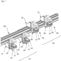
- Fig. 1 shows a perspective view of a guide beam 100 extending in a longitudinal direction.
- the guide beam 100 may extend from a loading station to a processing station so that workpieces can be moved between these stations.
- the guide support 100 has a first guide element 110 on a vertically upper side and a second guide element 120 on a vertically lower side. Furthermore, a third guide element 130 is arranged on a lateral region in the horizontal direction. The first guide element 110, the second guide element 120 and the third guide element 130 extend along the longitudinal direction of the guide support 100.
- a first guide carriage 10 and a second guide carriage 30 are guided by the second guide element 120, and the first guide carriage 10 and the second guide carriage 30 are supported by a first section 130-1 of the third guide element 130.
- the first guide carriage 10 and the second guide carriage 30 are thus movable along the longitudinal direction of the guide carrier 100.
- the first guide carriage 10, the second guide carriage 30 and the respective components provided thereon are referred to as the holding arrangement X1.
- a third guide carriage 50 and a fourth guide carriage 70 are guided along the longitudinal direction of the guide carrier 100.
- the third guide carriage 50 and the fourth guide carriage 70 are supported on a second section 130-2 of the third guide element 130.
- the first section 130-1 and the second section 130-2 of the guide element 130 are designed/arranged in such a way that, as explained below, the guide carriages can move past one another. According to a modification, it is also possible to design the first section and the second section as separate guide elements.
- the third guide carriage 50, the fourth guide carriage 70 and the respective components provided thereon are referred to as a further holding arrangement X2.
- the first guide carriage 10 accommodates a first holding element 20, the second guide carriage 30 a second holding element 40, the third guide carriage 50 a third holding element 60 and the fourth guide carriage 70 a fourth holding element 80.
- the holding elements 20, 40, 60 and 80 are movable in the vertical direction relative to the respective guide carriage in order to move from a basic position into a working position and vice versa.
- an extension carriage 25 is provided on the first guide carriage 10, which can be moved in the vertical direction from a basic position to a working position (and vice versa).
- the first holding element 20 is provided on this first extension carriage 25, which can be moved according to the movement of the extension carriage 25.
- a second extension carriage 45 is provided on the second guide carriage 30, which can be moved in a vertical direction similar to the first extension carriage 25 and receives the second holding element 40.
- a third extension slide 65 is provided on the third guide slide 50, which can also be moved in the vertical direction from a basic position to a working position (and vice versa) in order to move the third holding element 60 attached thereto in the vertical direction.
- a fourth extension slide 85 is provided on the fourth guide slide 70, which, similar to the extension slides described above, can be moved in a vertical direction from a basic position to a working position.
- the fourth extension slide 85 receives the fourth holding element 80 and can move it accordingly in a vertical direction.
- the first guide carriage 10, the second guide carriage 30 and the components attached thereto are designed as part of the holding arrangement X1 to receive and hold a plate-shaped workpiece by means of a coordinated movement and to move it along the guide carrier.
- the first holding element 20 comprises a first gripping unit 21 and a second gripping unit 22, which can be moved relative to one another in order to clamp a workpiece between them.
- the second holding element 40 comprises a first gripping unit 41 and a second gripping unit 42.
- the third holding element 60 comprises a first gripping unit 61 and a second gripping unit 62, which can each be moved relative to one another in order to clamp a workpiece between them.
- the fourth holding element 80 comprises a first gripping unit 81 and a second gripping unit 82.
- the first holding element 20 is in a working position
- the third holding element 60 is arranged in a basic position. Due to the working position of the first holding element 20 (as well as the second holding element 40 covered by the first holding element 20), the gripping units 41, 42 can be arranged in such a way that a workpiece held thereby is arranged with the gripping units 21, 22 in a working plane.
- the third holding element 60 as well as the second holding element 40 shown in the view in Fig. 2
- the fourth holding element 80 which is covered by the third holding element 60, is in a basic position, so that the third holding element 60 and the fourth holding element 80 can be moved along the guide carrier 100 without colliding with the first holding element 20 or the second holding element 40.
- Fig. 3 shows a plan view of an embodiment of a processing machine with a conveyor device according to the first embodiment.
- the processing machine comprises a loading station 200, a processing area 210 with several processing stations, a discharge station 220 and the conveyor device.
- the guide carrier 100 of the The conveyor system extends between the loading station 200, the processing area 210 with the processing stations and the discharge station 220.
- the holding arrangement X1 and the further holding arrangement X2 are arranged so that they can move along the guide support 100.
- Each of the holding arrangements X1, X2 holds a workpiece W, so that workpieces are moved from the loading station 200 to the processing area and then to the discharge station 220.
- the holding elements of this holding arrangement are moved from the working position to the basic position, so that the holding arrangement can be moved along the guide support 100 to the loading station 200 and in doing so passes the other holding arrangement.
- a loading station 200 and a discharge station 220 are provided in the embodiment shown, according to a modification, a combined loading and/or discharge station can be provided instead of the loading station 200.
- the discharge station 220 can be provided or omitted.
- a guide carrier 100a which extends in a longitudinal direction similar to the guide carrier 100 of the first embodiment.
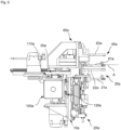
- a first holding element, a second holding element, a third holding element and a fourth holding element are movable along the guide carrier 100a, wherein for illustration purposes in Fig. 4 similar to the representation according to Figure 2 Only a first holding element 20a and a third holding element 60a are shown and explained below.
- the first holding element 20a comprises a first gripping unit 21a and a second gripping unit 22a, which can be moved relative to each other in order to clamp a workpiece between them.
- the third holding element 60a comprises a first gripping unit 61a and a second gripping unit 62a, which can each be moved relative to one another in order to clamp a workpiece between them.
- the guide carrier 100a has a first guide element 110a on a vertically upper side of the guide carrier 100a. Furthermore, a further guide element 130a is provided on a first side.
- first guide carriage 10a Along the further guide element 130a, a first guide carriage 10a and a second guide carriage (in Fig. 4 / Fig. 5 concealed by the first guide carriage).
- a third guide carriage 50a and a fourth guide carriage (in Fig. 4 / Fig. 5 concealed by the third guide carriage).
- a second extension carriage 25a is movable along the first guide carriage 10a in the vertical direction, so that the first holding element 20a can be moved in the vertical direction from a rest position to a working position. In the working position of the first holding element 20a (in Fig. 4 shown), a workpiece can be held in a working plane A by means of the first holding element 20a.
- the third holding element 60a comprises a first gripping unit 61a and a second gripping unit 62a, wherein the first Gripping unit 61a can be moved in the vertical direction relative to the second gripping unit 62a to clamp a workpiece.
- a third extension slide 65a is movable in the horizontal direction along the third guide slide 50a in order to move a third holding element 60a from a basic position into a working position.
- the third holding element 60a is in a basic position.
- the third holding element 60a and the fourth holding element can be moved along the guide carrier 100 without colliding with the second holding element 40a and the first holding element (not shown) in the working position.
- Fig. 5 is a representation of the second embodiment in which the third holding element 60a is in the working position, whereas the first holding element 20a has been moved into a basic position.
- the third holding element 60a is arranged in the working position such that a workpiece can be held in the working plane A.
- the first holding element 20a is arranged in the basic position such that it does not collide with the third holding element 60a.
- a processing machine with the conveyor device according to the second embodiment can be designed the same or similar to that already described with reference to Fig. 3 was explained. Reference is therefore made to this.
- Fig. 6 shows a perspective view of the third embodiment.
- a guide carrier 100b is provided which extends in a longitudinal direction and runs, for example, from a loading station to a processing station.
- Fig. 6 shows a perspective view of a guide beam 100b extending in a longitudinal direction.
- the guide beam 100b may extend from a loading station to a processing station so that workpieces can be moved between these stations.
- the guide carrier 100b has a guide element 110b on an upper side in the vertical direction and a further guide element 130b on a lateral side in the horizontal direction.
- a first guide carriage 10b, a second guide carriage 30b and the respective components provided thereon are provided on the guide carrier 100b.
- the first guide carriage 10b, the second guide carriage 30b and the respective components provided thereon are referred to as the holding arrangement X1b.
- a third guide carriage 50b and a fourth guide carriage 70b are movable along the longitudinal direction of the guide carrier 100b.
- the third guide carriage 50b, the fourth guide carriage 70b and the respective components provided thereon are referred to as a further holding arrangement X2b.
- the first guide carriage 10b and the second guide carriage 30b are guided by the guide element 110b, and the third guide carriage 50b and the fourth guide carriage 70b are guided by the further guide element 130b.
- the first guide carriage 10b takes a first holding element 20b, the second guide carriage 30b a second holding element 40b, the third guide carriage 50b a third holding element 60b and the fourth guide carriage 70b have a fourth holding element 80b.
- the first holding element 20b is pivotally connected to the first guide carriage 10b about a first, horizontally oriented axis 15b and the second holding element 40b is pivotally connected to the second guide carriage 30b about a second, horizontally oriented axis 35b.
- the third holding element 60b is pivotally connected to the third guide carriage 50b about a third, vertically aligned axis 55b and the fourth holding element 80b is pivotally connected to the fourth guide carriage 75b about a fourth, vertically aligned axis 75b.
- the holding elements 20b, 40b, 60b and 80b can thus be pivoted about a respective axis in order to move from a basic position to a working position and vice versa.
- an extension carriage 25b is provided on the first guide carriage 10b.
- the first holding element 20b is provided on this first extension carriage 25b and can be pivoted in accordance with the movement of the extension carriage 25b.
- a second extension slide 45b is provided on the second guide slide 30b, which can be pivoted similarly to the first extension slide 25b and receives the second holding element 40b.
- a third extension slide 65b is provided on the third guide slide 50b, which can also be pivoted from a basic position into a working position (and vice versa) in order to rotate the third holding element 60b attached thereto about the vertically aligned axis 55b.
- a fourth extension slide 85b is provided on the fourth guide slide 70b, which can be rotated from a basic position into a working position in a similar way to the extension slides described above.
- the fourth extension slide 85b accommodates the fourth holding element 80b.
- the first guide carriage 10b, the second guide carriage 30b and the components attached thereto are designed as part of the holding arrangement X1b to receive a plate-shaped workpiece by means of a coordinated movement, to hold it and to move it along the guide carrier.
- the first holding element 20b comprises a first gripping unit 21b and a second gripping unit 22b, which can be moved relative to one another in order to clamp a workpiece therebetween.
- the second holding element 40b comprises a first gripping unit 41b and a second gripping unit 42b.
- the third holding element 60b comprises a first gripping unit 61b and a second gripping unit 62b, which can each be moved relative to one another in order to clamp a workpiece therebetween. Furthermore, the fourth holding element 80b comprises a first gripping unit 81b and a second gripping unit 82b.
- the first holding element 20b is in a working position, whereas the second holding element 40b is in a basic position. Furthermore, the third holding element 60b is in a basic position, whereas the fourth holding element 80b is in a working position.
- This illustration clearly shows that the first holding element 20b and the third holding element 60b can be moved past one another. The same applies to the second holding element 40b and the fourth holding element 80b.
- the first holding element 20b and the second holding element 40b will be in the respective basic position or working position, whereas the third holding element 60b and the fourth holding element 80b will be in the other position (working position or basic position), or vice versa.
Landscapes
- Engineering & Computer Science (AREA)
- Life Sciences & Earth Sciences (AREA)
- Mechanical Engineering (AREA)
- Wood Science & Technology (AREA)
- Forests & Forestry (AREA)
- Screw Conveyors (AREA)
- Liquid Crystal (AREA)
- Formation And Processing Of Food Products (AREA)
- Feeding Of Workpieces (AREA)
Applications Claiming Priority (1)
| Application Number | Priority Date | Filing Date | Title |
|---|---|---|---|
| DE102023112439.0A DE102023112439A1 (de) | 2023-05-11 | 2023-05-11 | Fördereinrichtung |
Publications (1)
| Publication Number | Publication Date |
|---|---|
| EP4461676A1 true EP4461676A1 (fr) | 2024-11-13 |
Family
ID=91073124
Family Applications (1)
| Application Number | Title | Priority Date | Filing Date |
|---|---|---|---|
| EP24175126.2A Pending EP4461676A1 (fr) | 2023-05-11 | 2024-05-10 | Dispositif de transport |
Country Status (2)
| Country | Link |
|---|---|
| EP (1) | EP4461676A1 (fr) |
| DE (1) | DE102023112439A1 (fr) |
Cited By (1)
| Publication number | Priority date | Publication date | Assignee | Title |
|---|---|---|---|---|
| EP4691722A1 (fr) | 2024-08-07 | 2026-02-11 | Paride Sacchi | Machine pour le traitement simultané de pièces et procédé pour le traitement simultané de pièces avec cette machine |
Citations (6)
| Publication number | Priority date | Publication date | Assignee | Title |
|---|---|---|---|---|
| US4251957A (en) * | 1977-11-24 | 1981-02-24 | Toyoda-Koki Kabushiki-Kaisha | Workpiece transfer apparatus for a plurality of machine tools |
| JPH1111633A (ja) * | 1997-06-20 | 1999-01-19 | Fujitsu Ltd | 搬送装置及び搬送方法 |
| EP2168714A1 (fr) | 2008-09-25 | 2010-03-31 | Weeke Bohrsysteme GmbH | Dispositif de transport et d'usinage |
| EP3936462A1 (fr) * | 2020-07-07 | 2022-01-12 | Manz AG | Installation de transport pourvu de dispositifs essieux linéaires |
| EP3173361B1 (fr) * | 2015-11-26 | 2022-03-23 | Pablo Germade Castiñeiras | Système de transport pour machines d'emballage |
| EP4215327A1 (fr) * | 2022-01-19 | 2023-07-26 | Impresa 2000 di Sacchi Paride S.r.l. | Machine de traitement de panneau et procédé de traitement de panneau avec ladite machine |
-
2023
- 2023-05-11 DE DE102023112439.0A patent/DE102023112439A1/de active Pending
-
2024
- 2024-05-10 EP EP24175126.2A patent/EP4461676A1/fr active Pending
Patent Citations (7)
| Publication number | Priority date | Publication date | Assignee | Title |
|---|---|---|---|---|
| US4251957A (en) * | 1977-11-24 | 1981-02-24 | Toyoda-Koki Kabushiki-Kaisha | Workpiece transfer apparatus for a plurality of machine tools |
| JPH1111633A (ja) * | 1997-06-20 | 1999-01-19 | Fujitsu Ltd | 搬送装置及び搬送方法 |
| EP2168714A1 (fr) | 2008-09-25 | 2010-03-31 | Weeke Bohrsysteme GmbH | Dispositif de transport et d'usinage |
| EP3173361B1 (fr) * | 2015-11-26 | 2022-03-23 | Pablo Germade Castiñeiras | Système de transport pour machines d'emballage |
| EP3936462A1 (fr) * | 2020-07-07 | 2022-01-12 | Manz AG | Installation de transport pourvu de dispositifs essieux linéaires |
| EP4215327A1 (fr) * | 2022-01-19 | 2023-07-26 | Impresa 2000 di Sacchi Paride S.r.l. | Machine de traitement de panneau et procédé de traitement de panneau avec ladite machine |
| EP4215327B1 (fr) | 2022-01-19 | 2024-07-24 | Impresa 2000 di Sacchi Paride S.r.l. | Machine de traitement de panneau et procédé de traitement de panneau avec ladite machine |
Cited By (1)
| Publication number | Priority date | Publication date | Assignee | Title |
|---|---|---|---|---|
| EP4691722A1 (fr) | 2024-08-07 | 2026-02-11 | Paride Sacchi | Machine pour le traitement simultané de pièces et procédé pour le traitement simultané de pièces avec cette machine |
Also Published As
| Publication number | Publication date |
|---|---|
| DE102023112439A1 (de) | 2024-11-14 |
Similar Documents
| Publication | Publication Date | Title |
|---|---|---|
| EP2143524B1 (fr) | Dispositif de transport d'une pièce usinée | |
| EP0945196B1 (fr) | Dispositif pour trier les pièces à d'une machine pour couper des pièces de travail | |
| EP4041501B1 (fr) | Procédé pour transporter et/ou manipuler des pièces | |
| EP3031572A1 (fr) | Dispositif de changement d'outil destine a etre utilise dans un centre d'usinage et centre d'usinage destine a l'usinage mecanique d'une piece a usiner | |
| EP1990160A2 (fr) | Foreuse avec alimentation en continu | |
| DE112017000548T5 (de) | Schneidtisch und Verfahren zur Bearbeitung eines plattenartigen Materials auf einem Schneidtisch | |
| EP1810801A1 (fr) | Système de fabrication de pièces en forme de plaques | |
| EP4461676A1 (fr) | Dispositif de transport | |
| DE102005034431A1 (de) | Werkzeugmaschine mit zumindest einer Bearbeitungseinheit sowie Verfahren zum Bearbeiten von Werkstücken mit einer derartigen Werkzeugmaschine | |
| EP3663035B1 (fr) | Machine-outil dotée d'une broche porte-outil et d'un portique de chargement | |
| EP2260975B1 (fr) | Rectifieuse plane et procédé de traitement de pièce usinée par rectification plane | |
| EP3475040B1 (fr) | Machine avec des zones de travail et méthode associée | |
| DE19853365A1 (de) | Verfahren und Vorrichtung zum Umformen | |
| EP0566770A1 (fr) | Procédé et dispositif pour diviser des panneaux et pour l'usinage de ces parties qui en résultant | |
| WO2020053002A1 (fr) | Machine-outil | |
| AT519221B1 (de) | Fertigungsanlage mit einem Klemmwerkzeug sowie Verfahren zur Anpassung einer Gesamtlänge einer Biegekante des Klemmwerkzeugs | |
| EP0489681B1 (fr) | Procédé et dispositif pour déplacer des pièces en forme de bandes ou de panneaux, empilés et juxtaposés sur une surface de support à faible coefficient de frottement | |
| DE102019209923B4 (de) | Verfahren zum Transportieren von Werkstückteilen | |
| EP1645379B1 (fr) | Procédé et centre d'usinage pour l'usinage de pièces en forme de plaque | |
| EP0283993A2 (fr) | Perceuse pour le perçage frontal et/ou latéral de panneaux ou de coupes planes | |
| DE102007043421A1 (de) | Werkzeugmaschine | |
| DE102018131527A1 (de) | Verfahren zum Verarbeiten plattenförmiger Werkstücke | |
| AT523639B1 (de) | Werkzeugmaschine | |
| DE202010008902U1 (de) | Metall-Fräsvorrichtung zum Bearbeiten von Längskanten eines Mehrkantprofils aus Metall | |
| EP4094910A1 (fr) | Procédé d'usinage d'une pièce tabulaire, ainsi que dispositif d'usinage |
Legal Events
| Date | Code | Title | Description |
|---|---|---|---|
| PUAI | Public reference made under article 153(3) epc to a published international application that has entered the european phase |
Free format text: ORIGINAL CODE: 0009012 |
|
| STAA | Information on the status of an ep patent application or granted ep patent |
Free format text: STATUS: THE APPLICATION HAS BEEN PUBLISHED |
|
| AK | Designated contracting states |
Kind code of ref document: A1 Designated state(s): AL AT BE BG CH CY CZ DE DK EE ES FI FR GB GR HR HU IE IS IT LI LT LU LV MC ME MK MT NL NO PL PT RO RS SE SI SK SM TR |
|
| STAA | Information on the status of an ep patent application or granted ep patent |
Free format text: STATUS: REQUEST FOR EXAMINATION WAS MADE |
|
| 17P | Request for examination filed |
Effective date: 20250414 |
|
| STAA | Information on the status of an ep patent application or granted ep patent |
Free format text: STATUS: EXAMINATION IS IN PROGRESS |
|
| TPAC | Observations filed by third parties |
Free format text: ORIGINAL CODE: EPIDOSNTIPA |
|
| 17Q | First examination report despatched |
Effective date: 20250715 |