EP4095072B1 - Dispositif d'alimentation de feuilles - Google Patents
Dispositif d'alimentation de feuilles Download PDFInfo
- Publication number
- EP4095072B1 EP4095072B1 EP21759804.4A EP21759804A EP4095072B1 EP 4095072 B1 EP4095072 B1 EP 4095072B1 EP 21759804 A EP21759804 A EP 21759804A EP 4095072 B1 EP4095072 B1 EP 4095072B1
- Authority
- EP
- European Patent Office
- Prior art keywords
- sheet
- width
- sheet group
- movement mechanism
- fork portion
- Prior art date
- Legal status (The legal status is an assumption and is not a legal conclusion. Google has not performed a legal analysis and makes no representation as to the accuracy of the status listed.)
- Active
Links
Images




Classifications
-
- B—PERFORMING OPERATIONS; TRANSPORTING
- B65—CONVEYING; PACKING; STORING; HANDLING THIN OR FILAMENTARY MATERIAL
- B65H—HANDLING THIN OR FILAMENTARY MATERIAL, e.g. SHEETS, WEBS, CABLES
- B65H83/00—Combinations of piling and depiling operations, e.g. performed simultaneously, of interest apart from the single operation of piling or depiling as such
- B65H83/02—Combinations of piling and depiling operations, e.g. performed simultaneously, of interest apart from the single operation of piling or depiling as such performed on the same pile or stack
-
- B—PERFORMING OPERATIONS; TRANSPORTING
- B65—CONVEYING; PACKING; STORING; HANDLING THIN OR FILAMENTARY MATERIAL
- B65H—HANDLING THIN OR FILAMENTARY MATERIAL, e.g. SHEETS, WEBS, CABLES
- B65H1/00—Supports or magazines for piles from which articles are to be separated
- B65H1/04—Supports or magazines for piles from which articles are to be separated adapted to support articles substantially horizontally, e.g. for separation from top of pile
-
- B—PERFORMING OPERATIONS; TRANSPORTING
- B65—CONVEYING; PACKING; STORING; HANDLING THIN OR FILAMENTARY MATERIAL
- B65H—HANDLING THIN OR FILAMENTARY MATERIAL, e.g. SHEETS, WEBS, CABLES
- B65H1/00—Supports or magazines for piles from which articles are to be separated
- B65H1/30—Supports or magazines for piles from which articles are to be separated with means for replenishing the pile during continuous separation of articles therefrom
-
- B—PERFORMING OPERATIONS; TRANSPORTING
- B65—CONVEYING; PACKING; STORING; HANDLING THIN OR FILAMENTARY MATERIAL
- B65H—HANDLING THIN OR FILAMENTARY MATERIAL, e.g. SHEETS, WEBS, CABLES
- B65H5/00—Feeding articles separated from piles; Feeding articles to machines
- B65H5/006—Feeding stacks of articles to machines
-
- B—PERFORMING OPERATIONS; TRANSPORTING
- B65—CONVEYING; PACKING; STORING; HANDLING THIN OR FILAMENTARY MATERIAL
- B65H—HANDLING THIN OR FILAMENTARY MATERIAL, e.g. SHEETS, WEBS, CABLES
- B65H5/00—Feeding articles separated from piles; Feeding articles to machines
- B65H5/06—Feeding articles separated from piles; Feeding articles to machines by rollers or balls, e.g. between rollers
- B65H5/066—Feeding articles separated from piles; Feeding articles to machines by rollers or balls, e.g. between rollers the articles resting on rollers or balls
-
- B—PERFORMING OPERATIONS; TRANSPORTING
- B65—CONVEYING; PACKING; STORING; HANDLING THIN OR FILAMENTARY MATERIAL
- B65H—HANDLING THIN OR FILAMENTARY MATERIAL, e.g. SHEETS, WEBS, CABLES
- B65H7/00—Controlling article feeding, separating, pile-advancing, or associated apparatus, to take account of incorrect feeding, absence of articles, or presence of faulty articles
- B65H7/02—Controlling article feeding, separating, pile-advancing, or associated apparatus, to take account of incorrect feeding, absence of articles, or presence of faulty articles by feelers or detectors
- B65H7/06—Controlling article feeding, separating, pile-advancing, or associated apparatus, to take account of incorrect feeding, absence of articles, or presence of faulty articles by feelers or detectors responsive to presence of faulty articles or incorrect separation or feed
- B65H7/10—Controlling article feeding, separating, pile-advancing, or associated apparatus, to take account of incorrect feeding, absence of articles, or presence of faulty articles by feelers or detectors responsive to presence of faulty articles or incorrect separation or feed responsive to incorrect side register
-
- B—PERFORMING OPERATIONS; TRANSPORTING
- B65—CONVEYING; PACKING; STORING; HANDLING THIN OR FILAMENTARY MATERIAL
- B65H—HANDLING THIN OR FILAMENTARY MATERIAL, e.g. SHEETS, WEBS, CABLES
- B65H2301/00—Handling processes for sheets or webs
- B65H2301/30—Orientation, displacement, position of the handled material
- B65H2301/33—Modifying, selecting, changing orientation
- B65H2301/332—Turning, overturning
- B65H2301/3321—Turning, overturning kinetic therefor
- B65H2301/33214—Turning, overturning kinetic therefor about an axis perpendicular to the direction of displacement and parallel to the surface of material
-
- B—PERFORMING OPERATIONS; TRANSPORTING
- B65—CONVEYING; PACKING; STORING; HANDLING THIN OR FILAMENTARY MATERIAL
- B65H—HANDLING THIN OR FILAMENTARY MATERIAL, e.g. SHEETS, WEBS, CABLES
- B65H2301/00—Handling processes for sheets or webs
- B65H2301/30—Orientation, displacement, position of the handled material
- B65H2301/33—Modifying, selecting, changing orientation
- B65H2301/333—Inverting
-
- B—PERFORMING OPERATIONS; TRANSPORTING
- B65—CONVEYING; PACKING; STORING; HANDLING THIN OR FILAMENTARY MATERIAL
- B65H—HANDLING THIN OR FILAMENTARY MATERIAL, e.g. SHEETS, WEBS, CABLES
- B65H2301/00—Handling processes for sheets or webs
- B65H2301/30—Orientation, displacement, position of the handled material
- B65H2301/36—Positioning; Changing position
- B65H2301/363—Positioning; Changing position of material in pile
-
- B—PERFORMING OPERATIONS; TRANSPORTING
- B65—CONVEYING; PACKING; STORING; HANDLING THIN OR FILAMENTARY MATERIAL
- B65H—HANDLING THIN OR FILAMENTARY MATERIAL, e.g. SHEETS, WEBS, CABLES
- B65H2404/00—Parts for transporting or guiding the handled material
- B65H2404/60—Other elements in face contact with handled material
- B65H2404/65—Other elements in face contact with handled material rotating around an axis parallel to face of material and perpendicular to transport direction, e.g. star wheel
- B65H2404/651—Other elements in face contact with handled material rotating around an axis parallel to face of material and perpendicular to transport direction, e.g. star wheel having at least one element, e.g. stacker/inverter
-
- B—PERFORMING OPERATIONS; TRANSPORTING
- B65—CONVEYING; PACKING; STORING; HANDLING THIN OR FILAMENTARY MATERIAL
- B65H—HANDLING THIN OR FILAMENTARY MATERIAL, e.g. SHEETS, WEBS, CABLES
- B65H2405/00—Parts for holding the handled material
- B65H2405/10—Cassettes, holders, bins, decks, trays, supports or magazines for sheets stacked substantially horizontally
- B65H2405/11—Parts and details thereof
- B65H2405/111—Bottom
-
- B—PERFORMING OPERATIONS; TRANSPORTING
- B65—CONVEYING; PACKING; STORING; HANDLING THIN OR FILAMENTARY MATERIAL
- B65H—HANDLING THIN OR FILAMENTARY MATERIAL, e.g. SHEETS, WEBS, CABLES
- B65H2405/00—Parts for holding the handled material
- B65H2405/10—Cassettes, holders, bins, decks, trays, supports or magazines for sheets stacked substantially horizontally
- B65H2405/11—Parts and details thereof
- B65H2405/114—Side, i.e. portion parallel to the feeding / delivering direction
-
- B—PERFORMING OPERATIONS; TRANSPORTING
- B65—CONVEYING; PACKING; STORING; HANDLING THIN OR FILAMENTARY MATERIAL
- B65H—HANDLING THIN OR FILAMENTARY MATERIAL, e.g. SHEETS, WEBS, CABLES
- B65H2405/00—Parts for holding the handled material
- B65H2405/30—Other features of supports for sheets
- B65H2405/35—Means for moving support
- B65H2405/351—Means for moving support shifting transversely to transport direction, e.g. for handling stepped piles
-
- B—PERFORMING OPERATIONS; TRANSPORTING
- B65—CONVEYING; PACKING; STORING; HANDLING THIN OR FILAMENTARY MATERIAL
- B65H—HANDLING THIN OR FILAMENTARY MATERIAL, e.g. SHEETS, WEBS, CABLES
- B65H2405/00—Parts for holding the handled material
- B65H2405/30—Other features of supports for sheets
- B65H2405/35—Means for moving support
- B65H2405/354—Means for moving support around an axis, e.g. horizontal
-
- B—PERFORMING OPERATIONS; TRANSPORTING
- B65—CONVEYING; PACKING; STORING; HANDLING THIN OR FILAMENTARY MATERIAL
- B65H—HANDLING THIN OR FILAMENTARY MATERIAL, e.g. SHEETS, WEBS, CABLES
- B65H2513/00—Dynamic entities; Timing aspects
- B65H2513/40—Movement
-
- B—PERFORMING OPERATIONS; TRANSPORTING
- B65—CONVEYING; PACKING; STORING; HANDLING THIN OR FILAMENTARY MATERIAL
- B65H—HANDLING THIN OR FILAMENTARY MATERIAL, e.g. SHEETS, WEBS, CABLES
- B65H2701/00—Handled material; Storage means
- B65H2701/10—Handled articles or webs
- B65H2701/17—Nature of material
- B65H2701/176—Cardboard
-
- B—PERFORMING OPERATIONS; TRANSPORTING
- B65—CONVEYING; PACKING; STORING; HANDLING THIN OR FILAMENTARY MATERIAL
- B65H—HANDLING THIN OR FILAMENTARY MATERIAL, e.g. SHEETS, WEBS, CABLES
- B65H2701/00—Handled material; Storage means
- B65H2701/10—Handled articles or webs
- B65H2701/17—Nature of material
- B65H2701/176—Cardboard
- B65H2701/1762—Corrugated
-
- B—PERFORMING OPERATIONS; TRANSPORTING
- B65—CONVEYING; PACKING; STORING; HANDLING THIN OR FILAMENTARY MATERIAL
- B65H—HANDLING THIN OR FILAMENTARY MATERIAL, e.g. SHEETS, WEBS, CABLES
- B65H2801/00—Application field
- B65H2801/03—Image reproduction devices
- B65H2801/21—Industrial-size printers, e.g. rotary printing press
-
- B—PERFORMING OPERATIONS; TRANSPORTING
- B65—CONVEYING; PACKING; STORING; HANDLING THIN OR FILAMENTARY MATERIAL
- B65H—HANDLING THIN OR FILAMENTARY MATERIAL, e.g. SHEETS, WEBS, CABLES
- B65H2801/00—Application field
- B65H2801/81—Packaging machines
Definitions
- the present invention relates to a sheet supply device suitable for supplying a sheet such as a corrugated board from a supply source device such as a corrugated machine to a supply destination device such as a box making machine or a printing machine.
- a sheet supply device for supplying sheets such as corrugated board from a supply source device such as a corrugated machine to a supply destination device such as a box making machine or a printing machine
- a sheet supply device having a configuration in which a sheet group including a plurality of flatly stacked sheets is lifted and, the front and back sides thereof are inverted, and the sheet group is transferred onto a conveyor, and the conveyor sequentially moves each sheet of the sheet group in a transport direction.
- This sheet supply device is also referred to as a prefeeder.
- a device for laterally moving and centering the sheet group is deployed upstream of the prefeeder.
- a lateral movement device that laterally moves and centers the sheet group.
- JP 2002 362764 A that describes a sheet supply device provided with a sheet inverting mount 10 (lift portion) including a sheet supporting unit 12 (frame) that supports the front side of stacked sheet SO (a group of sheets) and a table 11 (fork portion) including a comb-shape supporting arm 15, and a sheet transfer device (conveyor portion).
- the device has a structure that the stacked sheets SO is transferred into the sheet transfer device 40 by rotating the sheet inverting mount 10 by the sheet auxiliary arm 28 and the cylinder 29 (inverting mechanism) and moving the table 11 by a moving device 20 (fork moving mechanism).
- JP H05 85734U that describes a sheet supplying device for a sheet-fed printing machine, in particular, a sheet supplying device provided with a parallel-cross shaped lift mount on which a paper lamination is placed.
- JP S50 11271 U that describes an automatic supplying device that makes a sheet lamination such as corrugated board sheets uniform, lays down the sheet lamination, and automatically transfers the sheet lamination to a mechanical device of ensuing step.
- EP 0350926 A1 that describes a sheet finisher which can appropriately fold, sort, fasten and collect sheets which have come out of a copy machine and the like.
- EP 1036661 A2 that describes a sheet supply apparatus for supplying record sheet to an image forming apparatus, and more particularly to a sheet supply machine having a vertically movable sheet supplying table supporting a plurality of record sheets stacked thereon in which an image forming position to the record sheet can be adjusted by moving the sheet supplying table right and left.
- JP H04 75843 U2 that describes a sheet supplying position automatically adjusting device for a sheet-fed printer.
- each sheet can be appropriately processed on the downstream side, but an installation space for the centering device is required.
- a conveyor having a length equal to or longer than the maximum sheet length in the sheet transfer direction is required. Therefore, the longitudinal size of the entire device becomes large and the factory layout is restricted.
- the present invention has been invented focusing on such a problem, and an object of the present invention is to provide a sheet supply device capable of suppressing the longitudinal size of the entire device and securing the degree of freedom in factory layout.
- another object of the present case is to exhibit actions and effects derived by respective configurations shown in the embodiments for carrying out the invention described below, and exhibit actions and effects that cannot be obtained by the related art.
- the width-direction movement mechanism related to the centering of the sheet group is equipped in the lift portion of the sheet supply device, the longitudinal size of the entire device can be suppressed and the degree of freedom in the factory layout can be secured.
- Figs. 1A and 1B are a schematic side view and a schematic plan view illustrating an overall configuration of a sheet supply device according to each embodiment.
- the directions (up, down, upstream, downstream) in the figures represent directions based on a transport direction of the sheet supply device. Normally, since the sheet supply device is installed on a horizontal plane, the up-down direction of the sheet supply device coincides with the vertical direction. Additionally, the horizontal direction orthogonal to the transport direction is referred to as a device width direction (or simply a "width direction"). Additionally, the downstream side in the transport direction is referred to as the front, and the upstream side is referred to as the rear.
- the sheet supply device 1 (hereinafter, also simply referred to as a "supply device”) is deployed between a supply source device and a supply destination device, for example, between a corrugated machine (not shown) that manufactures a corrugated board and a box making machine (not shown) that processes the corrugated board into a box-making sheet material, and is used to supply a plurality of the corrugated boards manufactured by the corrugated machine to the box making machine.
- each sheet 50 constituting a plurality of sheets (hereinafter referred to as a "sheet group”) 50G is thick paperboard such as the corrugated board.
- the supply device 1 is configured as a sheet inversion type supply device, and includes a lift portion 10 a sheet group 50G in which a plurality of sheets 50 are stacked flat is mounted, and a conveyor portion 20 provided downstream of the lift portion 10.
- the lift portion 10 lifts and inverts the mounted sheet group 50G to transfer the sheet group to a portion directly upstream of the conveyor portion 20.
- the conveyor portion 20 moves the sheet group 50G in a transport direction.
- a direction in which the plurality of sheets 50 are stacked flat is referred to as a flat stacking direction.
- the lift portion 10 includes a fixed frame 11, a movable frame 12 having a frame portion that is rotatably supported by the fixed frame 11 via a rotating shaft 12a extending in the horizontal direction and extends in a flat stacking direction, and a fork portion 13 that is slidably supported by the movable frame 12 in the flat stacking direction and has the sheet group 50G mounted thereon.
- a movable frame 12 having a frame portion that is rotatably supported by the fixed frame 11 via a rotating shaft 12a extending in the horizontal direction and extends in a flat stacking direction
- a fork portion 13 that is slidably supported by the movable frame 12 in the flat stacking direction and has the sheet group 50G mounted thereon.
- the lift portion 10 is configured to include an inversion mechanism 14 that turns the fork portion 13 around a horizontal axis to lift and invert the mounted sheet group 50G, a fork movement mechanism 15 that slidably moves the fork portion 13 in the flat stacking direction, and a transfer control device 31 that controls the inversion mechanism 14 and the fork movement mechanism 15.
- each sheet 50 is in a horizontal or substantially horizontal state, that is, a state in which the flat stacking direction faces a vertical or substantially vertical direction (vertical posture).
- a two-dot chain line in Fig. 1A when the lifting and inverting by the inversion mechanism 14 is completed, each sheet 50 is inclined slightly downward from the vertical direction, that is, the flat stacking direction is inclined slightly downward from the horizontal (a forwardly inclined posture).
- the state of the lift portion 10 in which the sheet group 50G is in the vertical posture is referred to as an initial state
- the state of the lift portion 10 in which the sheet group 50G is in the forwardly inclined posture is referred to as an inversion completion state
- a state in the middle of the initial state to the inversion completion state is referred to as a transfer state.
- the position of a moving element (moving body) of the lift portion 10 in the initial state is referred to as an initial position
- the position of the moving element (moving body) of the lift portion 10 in the inversion completion state is referred to as an inversion completion position.
- the movable frame 12 includes pillars 12A and 12B on both sides in the device width direction and a plurality (here, four) elongated pillars 12C to 12F disposed between the pillars the 12A and 12B, as frame portions extending in the flat stacking direction. All the pillars 12A to 12F extend in the flat stacking direction and are disposed parallel to each other. Additionally, an elongated plate-shaped member 16 extending in the flat stacking direction is interposed between the pillars 12A to 12F.
- the pillars 12A to 12F and the plate-shaped member 16 constitute a support surface 16F that supports a leading edge surface of the sheet group 50G.
- the leading edge surface of the sheet group 50G is a surface constituted of a sheet edge portion facing forward before inversion and facing downward after inversion, and is a surface perpendicular to the flat stacking direction.
- the support surface 16F gradually receives the load of the sheet group 50G through the leading edge surface of the sheet group 50G so as to support the sheet group 50G.
- the fork portion 13 is provided on the support surface 16F side (front side) of the movable frame 12, an arc-shaped arch portion 12b is provided on a back side of the movable frame 12, and a girder portion 12c erected in the arc of the arch portion 12b is provided with the rotating shaft 12a that rotatably supports the movable frame 12.
- the fork portion 13 is cantileveredly supported by the movable frame 12 so as to protrude in a direction perpendicular to the support surface 16F.
- the fork portion 13 is constituted of four rod-shaped arm portions 13a to 13d parallel to each other.
- the fork portion 13 (arm portions 13a to 13d) has a mounting surface 13A facing vertically upward in the initial state, and the sheet group 50G is mounted on the mounting surface 13A.
- the mounting surface 13A is equipped with a plurality of suction portions 17 for suctioning the sheet 50 (referred to as a lowermost sheet 51) located on the lowermost side of the sheet group 50G.
- a vacuum pad that suctions the lowermost sheet 51 by a suction force caused by vacuum can be applied.
- a total of five lift conveyors 18 are cantileveredly fixed to the movable frame 12 between the arm portions 13a to 13d of the fork portion 13 and outside the arm portions 13a to 13d.
- Each lift conveyor 18 has a support surface facing vertically upward in the initial state, and the support surface of each lift conveyor 18 is provided with a conveyor 18A that transports the sheet group 50G to the mounting surface 13A of the fork portion 13.
- a roller conveyor can be applied to the conveyor 18A, and when the sheet group 50G is supplied from the corrugated machine (not shown), the sheet group 50G is transported to a position where the sheet group 50G hits the support surface 16F of the movable frame 12 on a forward end side in the transport direction by the conveyor 18A.
- the inversion mechanism 14 is configured to include a motor and a speed reducer provided on the fixed frame 11 side, and the movable frame 12 is rotated around the rotating shaft 12a horizontal to the fixed frame 11 to turn the fork portion 13 supported by the movable frame 12 around the horizontal axis, whereby the sheet group 50G mounted on the fork portion 13 is inverted while being lifted.
- the fork movement mechanism 15 is configured to include a chain and a chain wheel partially built in the movable frame 12, and a motor that drives the chain wheel, and slidably moves the fork portion 13 with respect to the movable frame 12. This slide movement moves the fork portion 13 upward in the flat stacking direction with respect to the movable frame 12, and is performed in parallel with the lifting and inverting of the sheet group 50G by the inversion mechanism 14.
- Such control of the inversion mechanism 14 and the fork movement mechanism 15 is performed by the transfer control device 31.
- the lift portion 10 returns from the inversion completion position to the initial position with the lowermost sheet 51 kept suctioned on the suction portion 17 of the fork portion 13, and releases the suction to eliminate the lowermost sheet 51. For this reason, a dispensing device 41 that eliminates the lowermost sheet 51 is provided.
- a roller conveyor device including a plurality of rollers 41a disposed between the arm portions 13a to 13d of the fork portion 13 and the lift conveyor 18 in a plan view at the initial position.
- the plurality of rollers 41a are all disposed parallel to the arm portions 13a to 13d and the lift conveyor 18 at the initial position, and are moved up and down in the vertical direction by an elevating mechanism (not shown). Additionally, at least some (here, all the rollers 41a) of the rollers 41a are rotated by a motor (not shown).
- the plurality of rollers 41a are always located at a retracted position vertically below the fork portion 13 so as not to interfere with the mounting of the sheet group 50G, and are is lifted to a use position vertically above the fork portion 13 to support and rotate the lowermost sheet 51 when performing dispensing processing is performed and by rotating, and thereby dispenses the lowermost sheet 51 to a lateral side of the device.
- the sheet on a tip side of the sheet group 50G (the sheet vertically above in the initial posture) may be tilted irrespective of before the supply to the downstream side due to an inertial force caused by the forward inclination and movement of the sheet group 50G.
- a moving sheet support 42 is equipped to abut against the tip side of the sheet group 50G to cooperate with the moving fork portion 13 in the flat stacking direction and support the fork portion 13 to be sandwiched from both sides in the flat stacking direction.
- the moving sheet support 42 includes a plurality of rollers 42a that abuts against the sheet on the tip side of the sheet group 50G.
- the plurality of rollers 42a are formed of a soft material such as resin so as to have a peripheral surface without angular portion so as to be capable of coming into soft contact with the sheet 50, and each arm 42c is rotatably equipped at the tip of the arm 42c rockably supported by the support 42b.
- Each arm 42c is integrally rocked, as shown by an arrow A1 in Fig. 1A , by a drive device (not shown) such as a motor between the use position shown by the solid line and the retracted position shown by the two-dot chain line in Figs. 1A , 2A, and 2B , so that the plurality of rollers 42a can simultaneously abut against the sheet on the tip side of the sheet group 50G at the use position, and the plurality of rollers 42a are retracted so as to be separated from the transfer path of the sheet group 50G at the retracted position.
- the support 42b is moved up and down as shown by an arrow A2 in Fig. 1A by the elevating drive device (not shown) in conformity with the size of the sheet group 50G.
- the conveyor portion 20 includes a first conveyor 21, a second conveyor 22, and a third conveyor 23 from upstream to downstream in the transport direction, which are provided in order so as to follow a hopper 24 of the box making machine on the downstream side.
- the first conveyor 21, the second conveyor 22, the third conveyor 23, and the hopper 24 each have a plurality of pulleys and an endless belt, and are driven by a drive mechanism such as a motor (not shown) and sequentially transport the sheet group 50G placed on the endless belt from upstream to downstream in the transport direction.
- Figs. 3A to 3E are schematic side views illustrating an aspect in which the lift portion 10 of the supply device is rotated from the vertical posture via a horizontal posture to the forwardly inclined posture
- Fig. 3A shows a state in which the lift portion 10 is in the vertical posture
- Figs. 3B and 3C show the process in which the lift portion 10 is rotated from the vertical posture to the forwardly inclined posture
- Figs. 3D and 3E show a state in which the lift portion 10 is rotated to the forwardly inclined posture.
- the sheet group 50G is mounted in a flat stacking state on the fork portion 13 in the initial state shown in Fig. 3A .
- the lift portion 10 is rotated in the transport direction from a hanging posture to the forwardly inclined posture while moving the fork portion 13 upward from below in the flat stacking direction.
- the sheets 50 other than the lowermost sheet 51 are turned over and inverted in order from the sheet at the highest position toward the front in the transport direction, and are transferred to the first conveyor 21.
- the lowermost sheet 51 remains on the fork portion 13 due to the suction of the suction portion 17, and is not transferred onto the first conveyor 21.
- the reference width-direction range is set within a range of ⁇ 50 mm with respect to a width-direction reference position (a width-direction center CL of the device).
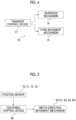
- the present device is equipped with a width-direction movement mechanism 60 that moves the mounted sheet group 50G in the width direction, a position sensor 70 that detects the width-direction position of the sheet group, and a centering control device 80 that controls the width-direction movement mechanism 60 on the basis of the detection information of the position sensor 70 and centers the width-direction position of the sheet group 50G within the reference width-direction range.
- the present case has a feature in that the centering is performed in the sheet supply device.
- first to fourth embodiments in which the specific configurations of the width-direction movement mechanisms 60 are different from each other will be described herein.
- a device related to the centering includes a roller conveyor device 61 as the width-direction movement mechanism, an initial position sensor 71 as the position sensor, the centering control device 80.
- the roller conveyor device 61 appropriately uses the above dispensing device 41 including the rollers 41a, which are disposed below the fork portion 13 at the initial position and are lifted and moved vertically upward from the fork portion 13 at the initial position to support the sheet group 50G to move the sheet group 50G in the width direction.
- the dispensing device 41 includes a plurality of rollers 41a disposed between the arm portions 13a to 13d of the fork portion 13 and the lift conveyor 18 in a plan view at the initial position, and the plurality of rollers 41a are provided are all disposed parallel to the arm portions 13a to 13d and the lift conveyor 18 at the initial position, are moved up and down in the vertical direction by the elevating mechanism (not shown), and are rotated by the motor (not shown).
- the plurality of rollers 41a are driven up to move up and down between the retracted position vertically below the fork portion 13 and the use position vertically above the fork portion 13, the dispensing device 41 is lifted to the use position and used when the lift portion 10 returns from the inversion completion position the initial position to eliminate the lowermost sheet 51.
- the roller conveyor device 61 is lifted to the use position and used immediately after the lift portion 10 is at the initial position and the sheet group 50G is mounted on the fork portion 13.
- the initial position sensor 71 detects the distance from a side edge portion of the sheet group 50G.
- Data of the size in the device width direction when the sheet group 50G is mounted is input to the centering control device 80.
- the centering control device 80 the positional deviation of the center of the sheet group 50G in the width direction with respect to the width-direction center CL of the device can be calculated from the position of the side edge portion of the sheet group 50G detected by the initial position sensor 71.
- the centering control device 80 determines whether or not the magnitude of the positional deviation is within a predetermined error range (the error range is, for example, ⁇ 50 mm), and when the magnitude of the positional deviation exceeds the predetermined error range, the roller conveyor device 61 is controlled to move the sheet group 50G in the width direction such that the magnitude of the positional deviation is within the predetermined error range.
- a predetermined error range the error range is, for example, ⁇ 50 mm
- the roller conveyor device 61 (dispensing device) 41 is controlled to move the sheet group 50G to the right as shown in Figs. 6B1 and 6B2.
- the plurality of rollers 41a are lifted from the retracted position vertically below the fork portion 13 as shown in Fig. 7A to the use position vertically above the fork portion 13 as shown in Fig. 7B to bring about a state in which the sheet group 50G is supported by the plurality of rollers 41a, and as shown in Fig. 7C , the plurality of rollers 41a is rotated by a predetermined amount in a predetermined direction to move the sheet group 50G by a predetermined amount of rotation in a predetermined direction. After the movement, the plurality of rollers 41a are lowered to the retracted position.
- the description of the lift conveyor 18 is omitted.
- the existing dispensing device 41 is utilized to suppress an increase in the longitudinal size of the entire device to secure the degree of freedom in the factory layout, and to suppress an increase in cost while performing the centering of the sheet group 50G.
- the centering of the sheet group 50G can be implemented by effectively utilizing the dispensing device 41 not only while the sheet group 50G is mounted on the fork portion 13 and the lift portion 10 is at the initial position but also until the fork portion 13 starts turning and lifting and the fork portion 13 moves above the plurality of rollers 41a.
- the centering control device 80 may stop the lift portion 10 at the initial position to reliably perform the centering of the sheet group 50G, but may perform the centering of the sheet group 50G utilizing the time until the fork portion 13 starts turning and lifting and the fork portion 13 moves above the plurality of rollers 41a. In this case, the time from the centering of the sheet group 50G to the completion of the inversion can be shortened.
- the dispensing device 41 is utilized as the roller conveyor device 61, but the present invention is not limited to this. Some rollers 41a of the plurality of rollers 41a of the dispensing device 41 may be utilized as the roller conveyor device 61, or dedicated rollers may be separately disposed to constitute the roller conveyor device 61 without using the dispensing device 41.
- the fork portion 13 includes a fork portion body 131 on which the sheet group 50G is mounted, a support 130 that movably supports the fork portion body 131 in the width direction, and a fork portion movement mechanism 62 that moves the fork portion body 131 in the width direction with respect to the support 130 to move the mounted sheet group 50G in the width direction using an actuator (not shown), and the fork portion movement mechanism 62 is applied to the width-direction movement mechanism 60.
- the description of the rollers 41a of the dispensing device 41 is omitted.
- the device related to centering includes the fork portion movement mechanism 62 as the width-direction movement mechanism, the initial position sensor 71 as the position sensor, and the centering control device 80. Similar to the first embodiment, the centering control device 80 controls the fork portion movement mechanism 62 on the basis of the detection information of the initial position sensor 71, and centers the width-direction position of the sheet group 50G within the reference width-direction range.
- the fork portion movement mechanism 62 can utilize, for example, a motor and a ball screw mechanism that converts the rotation of the motor into a linear motion, and can be configured by fixing the support 130 such that the axes of the motor and the ball screw shaft extend in the width direction and fixing a nut screwed to a ball screw shaft via a ball to the fork portion body 131.
- the fork portion body 131 is a moving body that moves in the width direction to move the sheet group 50G in the width direction.
- the transfer control device 31 (refer to Fig. 4 ) performs the initial position return control of returning the fork portion 10 to the initial position after the transfer of the sheet group 50G to the conveyor portion 20 is completed, but the centering control device 80 performs the neutral position return control of returning the fork portion body 131 as the moving body to a neutral position in the width direction during the initial position return control.
- the lift portion 10 is provided with the fork portion movement mechanism 62, so that the centering of the sheet group 50G can be performed while suppressing the increase in the longitudinal size of the entire device to secure the degree of freedom in the factory layout.
- the centering can be performed during the lifting and inverting of the sheet group 50G, the time from the centering of the sheet group 50G to the inversion completion state can be shortened.
- the neutral position return control of returning the fork portion body 131 to the neutral position in the width direction is performed during the initial position return control of returning the fork portion 10 to the initial position.
- the centering of the next sheet group 50G can be performed without any trouble.
- a movable base frame 11A which is a part of the fixed frame 11 of the lift portion 10, includes a frame movement mechanism 63 that is equipped on two rails 63a and 63a, extending in the device width direction, movable in the width direction, moves the movable base frame 11A in the width direction to move the mounted sheet group 50G in the width direction using an actuator (not shown), and the frame movement mechanism 63 is applied to the width-direction movement mechanism 60.
- the description of the rollers 41a of the dispensing device 41 is omitted.
- the device related to centering includes the frame movement mechanism 63 as the width-direction movement mechanism, the initial position sensor 71 as the position sensor, an inversion completion position sensor 72, and the centering control device 80. Similar to the first and second embodiments, the centering control device 80 controls the frame movement mechanism 63 on the basis of the detection information of the initial position sensor 71 and the inversion completion position sensor 72, and as shown in Figs. 10A and 10B , operates the frame movement mechanism 63 to center the width-direction position of the sheet group 50G within the reference width-direction range.
- the position of the sheet group 50G at the initial position is detected by the initial position sensor 71, a required width-direction movement amount of the sheet group 50G is calculated, and the frame movement mechanism 63 is controlled during the subsequent lifting and inverting movement to perform the centering of the sheet group 50G.
- the inversion completion position sensor 72 detects the position of the sheet group 50G at the stage of approaching the inversion completion position or the inversion completion position to confirm the centering result.
- the position of the sheet group 50G can be detected at an early stage, so that the time required for the centering can be sufficiently secured.
- the inversion completion position sensor 72 is equipped, the position of the sheet group 50G at a final stage can be detected, so that the allowance for the centering time is reduced, but the accuracy of the centering can be improved.
- the movable base frame 11A is a moving body that moves in the width direction to move the sheet group 50G in the width direction. Also in the present embodiment, after the transfer of the sheet group 50G to the conveyor portion 20 is completed, the transfer control device 31 performs the initial position return control of returning the fork portion 10 to the initial position, but the centering control device 80 performs the neutral position return control of returning the movable base frame 11A as the moving body to the neutral position in the width direction.
- the movable base frame 11A which is a part of the fixed frame 11, is included such that the frame movement mechanism 63 is movable in the width direction, so that the centering of the sheet group 50G can be performed while suppressing the increase in the longitudinal size of the entire device to secure the degree of freedom in the factory layout.
- the centering can be performed during the lifting and inverting of the sheet group 50G, the time from the centering of the sheet group 50G to the inversion completion state can be shortened.
- the neutral position return control of returning the movable base frame 11A to the neutral position in the width direction is performed during the initial position return control of returning the fork portion 10 to the initial position.
- the centering of the next sheet group 50G can be performed without any trouble.
- a gripping type movement mechanism 64 is included that grips the sheet group 50G to move the sheet group 50G in the width direction, and the gripping type movement mechanism 64 is applied to the width-direction movement mechanism 60.
- the gripping type movement mechanism 64 includes the arm portions 13a to 13d of the fork portion 13, the rollers 42a of the above transfer sheet support 42, and an actuator (not shown) that moves the arm portions 13a to 13d of the fork portion 13 and the rollers 42a of the transfer sheet support 42 in the width direction in synchronization with each other.
- the description of the rollers 41a of the dispensing device 41 is omitted.
- the gripping type movement mechanism 64 may be a mechanism that moves at least the arm portions 13a to 13d of the fork portion 13 and the rollers 42a of the transfer sheet support 42 in the width direction in synchronization with each other by the actuator (not shown).
- the fork portion 13 includes the support 130 and the fork portion body 131 that is movable in the width direction with respect to the support 130, and the arm portions 13a to 13d equipped on the fork portion body 131 are integrally moved in the width direction.
- a support member that supports the plurality of rollers 42a is made movable in the width direction and the support member is moved in the width direction to move the plurality of rollers 42a integrally in the width direction.
- the device related to centering includes the gripping type movement mechanism 64 as the width-direction movement mechanism, a gripping position sensor 73 as the position sensor, and the centering control device 80. Similar to the first to third embodiments, the centering control device 80 controls the gripping type movement mechanism 64, that is, the fork portion 13 and the moving sheet support 42 on the basis of the detection information of the gripping position sensor 73, and as shown in Figs. 12A and 12B , operates the gripping type movement mechanism 64 to center the width-direction position of the sheet group 50G within the reference width-direction range.
- the arm portions 13a to 13d of the fork portion 13 and the rollers 42a of the transfer sheet support 42 is a moving body that moves in the width direction to move the sheet group 50G in the width direction.
- the transfer control device 31 performs the initial position return control of returning the fork portion 10 to the initial position, but the centering control device 80 performs the neutral position return control of returning the arm portions 13a to 13d of the fork portion 13 and the roller 42a of the transfer sheet support 42 as the moving body to the neutral position in the width direction.
- the existing moving sheet support 42 is utilized to suppress an increase in the longitudinal size of the entire device to secure the degree of freedom in the factory layout, and to suppress an increase in cost while performing the centering of the sheet group 50G.
- the neutral position return control of returning the arm portions 13a to 13d of the fork portion 13 and the rollers 42a of the transfer sheet support 42 to the neutral position in the width direction is performed during the initial position return control of returning the fork portion 10 to the initial position.
- the centering of the next sheet group 50G can be performed without any trouble.
- the width-direction movement mechanisms are not limited to the above embodiments, and for example, a side jogger may be equipped on the lift portion and adopted for the width-direction movement mechanism.
- the width-direction movement mechanism only needs to be able to move the sheet group 50G in the width direction, and unlike the side jogger, it is not required to align the end edges of the sheets 50 in the width direction. However, by applying the side jogger, the centering of the sheet group 50G can be performed while aligning the end edges of the respective sheets 50 in the width direction, and the processing of the respective sheets on the downstream side can be more appropriately and easily performed.
- the reference width-direction range is set within a range of ⁇ 50 mm with respect to the width-direction reference position (the width-direction center CL of the device).
- an allowable width with respect to the width-direction reference position is not limited to the range of ⁇ 50 mm and can be set appropriately.
Landscapes
- Engineering & Computer Science (AREA)
- Mechanical Engineering (AREA)
- Sheets, Magazines, And Separation Thereof (AREA)
- Registering Or Overturning Sheets (AREA)
Claims (13)
- Dispositif d'alimentation de feuilles comprenant :une partie de levage (10) qui soulève et inverse un groupe de feuilles (50G) incluant une pluralité de feuilles empilées à plat (50) ;une partie de convoyeur (20) qui déplace chaque feuille (50) du groupe de feuilles (50G) transférée depuis la partie de levage (10) dans une direction de transport ;dans lequel la partie de levage (10) inclut un cadre (11) qui s'étend dans une direction d'empilement à plat du groupe de feuilles (50G), une partie de fourche (13) qui est supportée par le cadre (11) de manière à être mobile dans la direction d'empilement à plat et présente le groupe de feuilles (50G) monté sur celle-ci, un mécanisme d'inversion (14) qui fait tourner la partie de fourche (13) afin de soulever et d'inverser le groupe de feuilles monté (50G), et un mécanisme de déplacement de fourche (15) qui déplace la partie de fourche (13) dans la direction d'empilement à plat,caractérisé en ce que le dispositif d'alimentation de feuilles comprend en outreun mécanisme de déplacement dans une direction de largeur (60,61,62,63,64) qui est équipé sur la partie de levage (10) et déplace le groupe de feuilles monté (50G) dans une direction de largeur ;un détecteur de position (70,71,72,73) qui détecte une position dans la direction de largeur du groupe de feuilles (50G) ; etun dispositif de commande de centrage (80) qui commande le mécanisme de déplacement dans la direction de largeur (60,61,62,63,64) sur la base d'informations de détection du détecteur de position (70,71,72,73), et centre la position dans la direction de largeur du groupe de feuilles (50G) à l'intérieur d'une plage de direction de largeur de référence, à partir du moment où le groupe de feuilles (50G) est monté sur la partie de fourche (13) jusqu'au moment où le groupe de feuilles (50G) est transféré vers la partie de convoyeur (20).
- Dispositif d'alimentation de feuilles selon la revendication 1,
dans lequel le mécanisme de déplacement dans la direction de largeur (60) est un dispositif de convoyeur à rouleaux (61) incluant un rouleau (41a) qui est disposé en dessous de la partie de fourche abaissée (13) au niveau d'une position initiale et est soulevé et déplacé verticalement vers le haut depuis la partie de fourche (13) au niveau de la position initiale afin de soutenir le groupe de feuilles (50G) pour déplacer le groupe de feuilles (50G) dans la direction de largeur. - Dispositif d'alimentation de feuilles selon la revendication 2,
dans lequel un dispositif de distribution (41) qui déplace une feuille de couche la plus basse (51) du groupe de feuilles (50G) dans la direction de largeur et distribue la feuille de couche la plus basse (51) vers un côté latéral du dispositif de distribution (41) est appliqué sur le dispositif de convoyeur à rouleaux (61). - Dispositif d'alimentation de feuilles selon la revendication 2 ou la revendication 3,
dans lequel lorsque la partie de fourche (13) se trouve au niveau de la position initiale, le dispositif de commande de centrage commande le dispositif de convoyeur à rouleaux (61) sur la base des informations de détection du détecteur de position (70,71) et centre la position dans la direction de largeur du groupe de feuilles (50G) à l'intérieur de la plage de direction de largeur de référence. - Dispositif d'alimentation de feuilles selon la revendication 2 ou la revendication 3,
dans lequel lorsque la partie de fourche (13) est soulevée depuis la position initiale, le dispositif de commande de centrage (80) commande le dispositif de convoyeur à rouleaux (61) sur la base des informations de détection du détecteur de position (70,71) et centre la position dans la direction de largeur du groupe de feuilles (50G) à l'intérieur de la plage de direction de largeur de référence. - Dispositif d'alimentation de feuilles selon la revendication 1,dans lequel la partie de fourche (13) inclutun corps de partie de fourche (131) sur lequel le groupe de feuilles (50G) est monté,un support (42b) qui supporte de manière mobile le corps de partie de fourche (131) dans la direction de largeur, etun mécanisme de déplacement de partie de fourche (62) qui déplace le corps de partie de fourche (13) dans la direction de largeur par rapport au support (42b) afin de déplacer le groupe de feuilles monté (50G) dans la direction de largeur, etle mécanisme de déplacement dans la direction de largeur (60) est le mécanisme de déplacement de partie de fourche (62).
- Dispositif d'alimentation de feuilles selon la revendication 6,
dans lequel le dispositif de commande de centrage (80) commande le mécanisme de déplacement de partie de fourche (62) sur la base des informations de détection du détecteur de position (70,71) pendant que la partie de fourche (13) est soulevée ou inversée, et centre la position dans la direction de largeur du groupe de feuilles (50G) à l'intérieur de la plage de direction de largeur de référence. - Dispositif d'alimentation de feuilles selon la revendication 1,
dans lequel le mécanisme de déplacement dans la direction de largeur (60) est un mécanisme de déplacement de cadre (63) qui déplace le cadre (11) dans la direction de largeur afin de déplacer le groupe de feuilles monté (50G) dans la direction de largeur. - Dispositif d'alimentation de feuilles selon la revendication 8, comprenant en outre :deux rails (63a) qui s'étendent dans la direction de largeur ; etun cadre de base mobile (11A) qui est équipé sur les deux rails (63a) de manière à être mobile dans la direction de largeur et forme une partie du cadre (11),dans lequel le mécanisme de déplacement (63) de cadre (11) déplace le cadre de base mobile (11A) dans la direction de largeur afin de déplacer le groupe de feuilles monté (50G) dans la direction de largeur.
- Dispositif d'alimentation de feuilles selon la revendication 1, comprenant en outre :un mécanisme de déplacement de type à préhension (64) qui saisit le groupe de feuilles (50G) afin de déplacer le groupe de feuilles (50G) dans la direction de largeur lorsque le groupe de feuilles (50G) est au niveau d'une position soulevée et inversée,dans lequel le mécanisme de déplacement de type à préhension (64) est appliqué sur le mécanisme de déplacement dans la direction de largeur (60).
- Dispositif d'alimentation de feuilles selon la revendication 10, comprenant en outre :un support de feuilles de transfert (42) qui est prévu de manière à faire face à la partie de fourche (13) lorsque le groupe de feuilles (50G) est au niveau d'une position soulevée et inversée, et saisit le groupe de feuilles (50G) à partir des deux côtés d'extrémité dans la direction d'empilement à plat en coopération avec la partie de fourche (13) afin de guider le transfert du groupe de feuilles (50G) vers la partie de convoyeur (20),dans lequel le mécanisme de déplacement de type à préhension (64) inclut la partie de fourche (13) et le support de feuilles de transfert (42).
- Dispositif d'alimentation de feuilles selon l'une quelconque des revendications 1, 6 à 11,dans lequel la partie de levage (10) inclut un dispositif de commande de transfert (80) qui commande le mécanisme d'inversion (14) et le mécanisme de déplacement de fourche (15),le mécanisme de déplacement dans la direction de largeur (60) inclut un corps en déplacement (13a,13b,13c,13d 42a) qui se déplace dans la direction de largeur afin de déplacer le groupe de feuilles (50G) dans la direction de largeur,le dispositif de commande de transfert (80) effectue une commande de retour en position initiale destinée à faire revenir la partie de fourche (13) vers la position initiale une fois que le transfert du groupe de feuilles (50G) vers la partie de convoyeur (20) est terminé, etle dispositif de commande de centrage (80) effectue une commande de retour en position neutre destinée à faire revenir le corps en déplacement (13a, 13b, 13c, 13d 42a) vers une position neutre dans la direction de largeur pendant la commande de retour en position initiale.
- Dispositif d'alimentation de feuilles selon l'une quelconque des revendications 1 à 12,
dans lequel la plage de direction de largeur de référence est dans une plage de ±50 mm par rapport à une position de référence dans la direction de largeur.
Applications Claiming Priority (2)
| Application Number | Priority Date | Filing Date | Title |
|---|---|---|---|
| JP2020029003A JP7458202B2 (ja) | 2020-02-25 | 2020-02-25 | シート供給装置 |
| PCT/JP2021/005765 WO2021172108A1 (fr) | 2020-02-25 | 2021-02-16 | Dispositif de distribution de feuille |
Publications (3)
| Publication Number | Publication Date |
|---|---|
| EP4095072A1 EP4095072A1 (fr) | 2022-11-30 |
| EP4095072A4 EP4095072A4 (fr) | 2023-11-08 |
| EP4095072B1 true EP4095072B1 (fr) | 2025-01-01 |
Family
ID=77491556
Family Applications (1)
| Application Number | Title | Priority Date | Filing Date |
|---|---|---|---|
| EP21759804.4A Active EP4095072B1 (fr) | 2020-02-25 | 2021-02-16 | Dispositif d'alimentation de feuilles |
Country Status (5)
| Country | Link |
|---|---|
| US (1) | US12037218B2 (fr) |
| EP (1) | EP4095072B1 (fr) |
| JP (1) | JP7458202B2 (fr) |
| CN (1) | CN115135590B (fr) |
| WO (1) | WO2021172108A1 (fr) |
Families Citing this family (1)
| Publication number | Priority date | Publication date | Assignee | Title |
|---|---|---|---|---|
| JP2024152139A (ja) * | 2023-04-14 | 2024-10-25 | 京セラドキュメントソリューションズ株式会社 | シート搬送装置、画像形成装置、動作制御方法 |
Family Cites Families (22)
| Publication number | Priority date | Publication date | Assignee | Title |
|---|---|---|---|---|
| JPS541738Y2 (fr) * | 1973-05-28 | 1979-01-25 | ||
| JPS5798444A (en) | 1980-12-12 | 1982-06-18 | Mitsubishi Heavy Ind Ltd | Alternately turning over apparatus for material being conveyed |
| JPS5978053A (ja) | 1982-10-26 | 1984-05-04 | Isowa Ind Co | 段ボ−ルシ−トの反転集積方法及びこれを実施するための装置 |
| JPS60133849U (ja) * | 1984-02-16 | 1985-09-06 | 凸版印刷株式会社 | 紙葉類の位置調整装置 |
| US5020785A (en) * | 1988-07-14 | 1991-06-04 | Ikegami Tsushiniki Co. Ltd. | Sheet finisher |
| JPH0475843U (fr) * | 1990-11-08 | 1992-07-02 | ||
| JPH0581131U (ja) | 1992-04-06 | 1993-11-02 | レンゴー株式会社 | 搬送位置調整装置を備えたシート搬送コンベヤ |
| JPH0585734U (ja) * | 1992-04-22 | 1993-11-19 | アキヤマ印刷機製造株式会社 | 枚葉印刷機の給紙装置 |
| US5743374A (en) * | 1995-08-25 | 1998-04-28 | Monsees; Claude E. | Stack turner and replenisher and method |
| US6595740B1 (en) * | 1998-04-17 | 2003-07-22 | Alliance Machine Systems International, Llc | Prefeeder assembly |
| JP2000233854A (ja) | 1999-02-15 | 2000-08-29 | Rengo Co Ltd | 積み重ねシートの反転装置 |
| JP2000264448A (ja) * | 1999-03-16 | 2000-09-26 | Riso Kagaku Corp | 給紙装置 |
| US6247694B1 (en) * | 1999-12-17 | 2001-06-19 | R. R. Donnelley & Sons Company | Automated bindery log extension |
| DE10161891B4 (de) * | 2001-01-19 | 2017-09-14 | Heidelberger Druckmaschinen Ag | Verfahren zur Regelung bogenförmiges Material führender Elemente |
| JP4462784B2 (ja) * | 2001-05-22 | 2010-05-12 | レンゴー株式会社 | 給紙装置 |
| JP2002356237A (ja) | 2001-05-29 | 2002-12-10 | Nikko Seisakusho:Kk | 自立性シート材の供給方法及び供給装置 |
| JP4515662B2 (ja) * | 2001-06-06 | 2010-08-04 | レンゴー株式会社 | 給紙方法 |
| DE10310697A1 (de) * | 2003-03-12 | 2004-09-23 | Koenig & Bauer Ag | Bogenanleger |
| JP4789844B2 (ja) * | 2007-03-30 | 2011-10-12 | 大日本スクリーン製造株式会社 | 刷版供給装置 |
| DE102010049376A1 (de) * | 2010-10-26 | 2012-04-26 | Heidelberger Druckmaschinen Ag | Vorrichtung und Verfahren zum Wenden von Stapeln aus bogenförmigem Material |
| JP2015044682A (ja) | 2013-08-29 | 2015-03-12 | 尚安 杉本 | 板紙類供給装置 |
| JP6128105B2 (ja) * | 2014-11-28 | 2017-05-17 | コニカミノルタ株式会社 | 用紙搬送装置及び画像形成装置 |
-
2020
- 2020-02-25 JP JP2020029003A patent/JP7458202B2/ja active Active
-
2021
- 2021-02-16 WO PCT/JP2021/005765 patent/WO2021172108A1/fr not_active Ceased
- 2021-02-16 CN CN202180014887.8A patent/CN115135590B/zh active Active
- 2021-02-16 US US17/797,277 patent/US12037218B2/en active Active
- 2021-02-16 EP EP21759804.4A patent/EP4095072B1/fr active Active
Also Published As
| Publication number | Publication date |
|---|---|
| CN115135590A (zh) | 2022-09-30 |
| WO2021172108A1 (fr) | 2021-09-02 |
| US20230339709A1 (en) | 2023-10-26 |
| JP2021134014A (ja) | 2021-09-13 |
| EP4095072A1 (fr) | 2022-11-30 |
| CN115135590B (zh) | 2025-07-11 |
| EP4095072A4 (fr) | 2023-11-08 |
| US12037218B2 (en) | 2024-07-16 |
| JP7458202B2 (ja) | 2024-03-29 |
Similar Documents
| Publication | Publication Date | Title |
|---|---|---|
| US20080006981A1 (en) | Method and device for forming stacks of flat elements | |
| KR102173674B1 (ko) | 시트재 취급 방법, 및 시트재 취급 장치 | |
| JP3478629B2 (ja) | 紙葉処理機械の給紙領域において紙葉を搬送する装置および電動モータの速度制御方法 | |
| EP4095072B1 (fr) | Dispositif d'alimentation de feuilles | |
| JP2006347694A (ja) | シート束搬送装置及びこれを用いた製本装置 | |
| EP1085382B1 (fr) | Procédé de positionnement et dispositif de positionnement | |
| JP4152401B2 (ja) | シート束搬送装置 | |
| EP3685934B1 (fr) | Système de transport de pièces à usiner, détecteur du nombre de pièces à usiner transportées et procédé de commande du système de transport de pièces à usiner | |
| JP2008162760A (ja) | ガラス搬送ロボットハンド | |
| JPH08301504A (ja) | シ−ト整合装置及びそれを備えた製本装置 | |
| JPH05213487A (ja) | 給紙装置 | |
| JP4757222B2 (ja) | 刷版供給装置 | |
| JP2003154583A (ja) | 段ボールの糊付け装置及び製造システム | |
| JP4650973B2 (ja) | 枚葉紙を加工する機械の給紙機において枚葉紙の積紙を位置調整する方法 | |
| US20190055100A1 (en) | Device for the linear corrective transport of ribbon-shaped substrates | |
| JPH1045306A (ja) | 印刷済み製品を別の処理箇所まで搬送するための装置 | |
| JPH07157098A (ja) | 折丁供給装置 | |
| JP2002346983A (ja) | 積載シートの断裁装置 | |
| US20260028198A1 (en) | Sheet feeding apparatus | |
| JPS60244742A (ja) | 給紙装置 | |
| JP2537510Y2 (ja) | 積重シートの搬出装置 | |
| JP2009029553A (ja) | シート状ワークの給紙方法及びシート状ワークの給紙装置。 | |
| JP3638368B2 (ja) | 用紙区分けスタッカ装置 | |
| WO2025248581A1 (fr) | Dispositif de transfert | |
| JPH0249243Y2 (fr) |
Legal Events
| Date | Code | Title | Description |
|---|---|---|---|
| STAA | Information on the status of an ep patent application or granted ep patent |
Free format text: STATUS: THE INTERNATIONAL PUBLICATION HAS BEEN MADE |
|
| PUAI | Public reference made under article 153(3) epc to a published international application that has entered the european phase |
Free format text: ORIGINAL CODE: 0009012 |
|
| STAA | Information on the status of an ep patent application or granted ep patent |
Free format text: STATUS: REQUEST FOR EXAMINATION WAS MADE |
|
| 17P | Request for examination filed |
Effective date: 20220824 |
|
| AK | Designated contracting states |
Kind code of ref document: A1 Designated state(s): AL AT BE BG CH CY CZ DE DK EE ES FI FR GB GR HR HU IE IS IT LI LT LU LV MC MK MT NL NO PL PT RO RS SE SI SK SM TR |
|
| DAV | Request for validation of the european patent (deleted) | ||
| DAX | Request for extension of the european patent (deleted) | ||
| REG | Reference to a national code |
Ref country code: DE Ref legal event code: R079 Free format text: PREVIOUS MAIN CLASS: B65H0001140000 Ipc: B65H0001300000 Ref document number: 602021024297 Country of ref document: DE |
|
| A4 | Supplementary search report drawn up and despatched |
Effective date: 20231009 |
|
| RIC1 | Information provided on ipc code assigned before grant |
Ipc: B65H 1/04 20060101ALI20231002BHEP Ipc: B65H 83/02 20060101ALI20231002BHEP Ipc: B65H 1/30 20060101AFI20231002BHEP |
|
| GRAP | Despatch of communication of intention to grant a patent |
Free format text: ORIGINAL CODE: EPIDOSNIGR1 |
|
| STAA | Information on the status of an ep patent application or granted ep patent |
Free format text: STATUS: GRANT OF PATENT IS INTENDED |
|
| INTG | Intention to grant announced |
Effective date: 20240903 |
|
| GRAS | Grant fee paid |
Free format text: ORIGINAL CODE: EPIDOSNIGR3 |
|
| GRAA | (expected) grant |
Free format text: ORIGINAL CODE: 0009210 |
|
| STAA | Information on the status of an ep patent application or granted ep patent |
Free format text: STATUS: THE PATENT HAS BEEN GRANTED |
|
| AK | Designated contracting states |
Kind code of ref document: B1 Designated state(s): AL AT BE BG CH CY CZ DE DK EE ES FI FR GB GR HR HU IE IS IT LI LT LU LV MC MK MT NL NO PL PT RO RS SE SI SK SM TR |
|
| REG | Reference to a national code |
Ref country code: GB Ref legal event code: FG4D |
|
| P01 | Opt-out of the competence of the unified patent court (upc) registered |
Free format text: CASE NUMBER: APP_63263/2024 Effective date: 20241128 |
|
| REG | Reference to a national code |
Ref country code: CH Ref legal event code: EP |
|
| REG | Reference to a national code |
Ref country code: DE Ref legal event code: R096 Ref document number: 602021024297 Country of ref document: DE |
|
| REG | Reference to a national code |
Ref country code: IE Ref legal event code: FG4D |
|
| REG | Reference to a national code |
Ref country code: NL Ref legal event code: FP |
|
| PGFP | Annual fee paid to national office [announced via postgrant information from national office to epo] |
Ref country code: AT Payment date: 20250417 Year of fee payment: 5 |
|
| REG | Reference to a national code |
Ref country code: LT Ref legal event code: MG9D |
|
| REG | Reference to a national code |
Ref country code: AT Ref legal event code: MK05 Ref document number: 1756060 Country of ref document: AT Kind code of ref document: T Effective date: 20250101 |
|
| PG25 | Lapsed in a contracting state [announced via postgrant information from national office to epo] |
Ref country code: FI Free format text: LAPSE BECAUSE OF FAILURE TO SUBMIT A TRANSLATION OF THE DESCRIPTION OR TO PAY THE FEE WITHIN THE PRESCRIBED TIME-LIMIT Effective date: 20250101 |
|
| PG25 | Lapsed in a contracting state [announced via postgrant information from national office to epo] |
Ref country code: PL Free format text: LAPSE BECAUSE OF FAILURE TO SUBMIT A TRANSLATION OF THE DESCRIPTION OR TO PAY THE FEE WITHIN THE PRESCRIBED TIME-LIMIT Effective date: 20250101 |
|
| PG25 | Lapsed in a contracting state [announced via postgrant information from national office to epo] |
Ref country code: ES Free format text: LAPSE BECAUSE OF FAILURE TO SUBMIT A TRANSLATION OF THE DESCRIPTION OR TO PAY THE FEE WITHIN THE PRESCRIBED TIME-LIMIT Effective date: 20250101 |
|
| PG25 | Lapsed in a contracting state [announced via postgrant information from national office to epo] |
Ref country code: IS Free format text: LAPSE BECAUSE OF FAILURE TO SUBMIT A TRANSLATION OF THE DESCRIPTION OR TO PAY THE FEE WITHIN THE PRESCRIBED TIME-LIMIT Effective date: 20250501 Ref country code: NO Free format text: LAPSE BECAUSE OF FAILURE TO SUBMIT A TRANSLATION OF THE DESCRIPTION OR TO PAY THE FEE WITHIN THE PRESCRIBED TIME-LIMIT Effective date: 20250401 |
|
| PG25 | Lapsed in a contracting state [announced via postgrant information from national office to epo] |
Ref country code: HR Free format text: LAPSE BECAUSE OF FAILURE TO SUBMIT A TRANSLATION OF THE DESCRIPTION OR TO PAY THE FEE WITHIN THE PRESCRIBED TIME-LIMIT Effective date: 20250101 |
|
| PG25 | Lapsed in a contracting state [announced via postgrant information from national office to epo] |
Ref country code: PT Free format text: LAPSE BECAUSE OF FAILURE TO SUBMIT A TRANSLATION OF THE DESCRIPTION OR TO PAY THE FEE WITHIN THE PRESCRIBED TIME-LIMIT Effective date: 20250502 Ref country code: LV Free format text: LAPSE BECAUSE OF FAILURE TO SUBMIT A TRANSLATION OF THE DESCRIPTION OR TO PAY THE FEE WITHIN THE PRESCRIBED TIME-LIMIT Effective date: 20250101 |
|
| PG25 | Lapsed in a contracting state [announced via postgrant information from national office to epo] |
Ref country code: BG Free format text: LAPSE BECAUSE OF FAILURE TO SUBMIT A TRANSLATION OF THE DESCRIPTION OR TO PAY THE FEE WITHIN THE PRESCRIBED TIME-LIMIT Effective date: 20250101 Ref country code: GR Free format text: LAPSE BECAUSE OF FAILURE TO SUBMIT A TRANSLATION OF THE DESCRIPTION OR TO PAY THE FEE WITHIN THE PRESCRIBED TIME-LIMIT Effective date: 20250402 |
|
| PG25 | Lapsed in a contracting state [announced via postgrant information from national office to epo] |
Ref country code: AT Free format text: LAPSE BECAUSE OF FAILURE TO SUBMIT A TRANSLATION OF THE DESCRIPTION OR TO PAY THE FEE WITHIN THE PRESCRIBED TIME-LIMIT Effective date: 20250101 |
|
| PG25 | Lapsed in a contracting state [announced via postgrant information from national office to epo] |
Ref country code: CZ Free format text: LAPSE BECAUSE OF FAILURE TO SUBMIT A TRANSLATION OF THE DESCRIPTION OR TO PAY THE FEE WITHIN THE PRESCRIBED TIME-LIMIT Effective date: 20250101 |
|
| PG25 | Lapsed in a contracting state [announced via postgrant information from national office to epo] |
Ref country code: SE Free format text: LAPSE BECAUSE OF FAILURE TO SUBMIT A TRANSLATION OF THE DESCRIPTION OR TO PAY THE FEE WITHIN THE PRESCRIBED TIME-LIMIT Effective date: 20250101 |
|
| REG | Reference to a national code |
Ref country code: DE Ref legal event code: R097 Ref document number: 602021024297 Country of ref document: DE |
|
| PG25 | Lapsed in a contracting state [announced via postgrant information from national office to epo] |
Ref country code: SM Free format text: LAPSE BECAUSE OF FAILURE TO SUBMIT A TRANSLATION OF THE DESCRIPTION OR TO PAY THE FEE WITHIN THE PRESCRIBED TIME-LIMIT Effective date: 20250101 |
|
| PG25 | Lapsed in a contracting state [announced via postgrant information from national office to epo] |
Ref country code: DK Free format text: LAPSE BECAUSE OF FAILURE TO SUBMIT A TRANSLATION OF THE DESCRIPTION OR TO PAY THE FEE WITHIN THE PRESCRIBED TIME-LIMIT Effective date: 20250101 |
|
| PG25 | Lapsed in a contracting state [announced via postgrant information from national office to epo] |
Ref country code: MC Free format text: LAPSE BECAUSE OF FAILURE TO SUBMIT A TRANSLATION OF THE DESCRIPTION OR TO PAY THE FEE WITHIN THE PRESCRIBED TIME-LIMIT Effective date: 20250101 |
|
| PG25 | Lapsed in a contracting state [announced via postgrant information from national office to epo] |
Ref country code: LU Free format text: LAPSE BECAUSE OF NON-PAYMENT OF DUE FEES Effective date: 20250216 |
|
| PG25 | Lapsed in a contracting state [announced via postgrant information from national office to epo] |
Ref country code: EE Free format text: LAPSE BECAUSE OF FAILURE TO SUBMIT A TRANSLATION OF THE DESCRIPTION OR TO PAY THE FEE WITHIN THE PRESCRIBED TIME-LIMIT Effective date: 20250101 |
|
| PG25 | Lapsed in a contracting state [announced via postgrant information from national office to epo] |
Ref country code: RO Free format text: LAPSE BECAUSE OF FAILURE TO SUBMIT A TRANSLATION OF THE DESCRIPTION OR TO PAY THE FEE WITHIN THE PRESCRIBED TIME-LIMIT Effective date: 20250101 |
|
| PG25 | Lapsed in a contracting state [announced via postgrant information from national office to epo] |
Ref country code: SK Free format text: LAPSE BECAUSE OF FAILURE TO SUBMIT A TRANSLATION OF THE DESCRIPTION OR TO PAY THE FEE WITHIN THE PRESCRIBED TIME-LIMIT Effective date: 20250101 |
|
| PLBE | No opposition filed within time limit |
Free format text: ORIGINAL CODE: 0009261 |
|
| STAA | Information on the status of an ep patent application or granted ep patent |
Free format text: STATUS: NO OPPOSITION FILED WITHIN TIME LIMIT |
|
| REG | Reference to a national code |
Ref country code: CH Ref legal event code: L10 Free format text: ST27 STATUS EVENT CODE: U-0-0-L10-L00 (AS PROVIDED BY THE NATIONAL OFFICE) Effective date: 20251112 |
|
| REG | Reference to a national code |
Ref country code: BE Ref legal event code: MM Effective date: 20250228 |
|
| 26N | No opposition filed |
Effective date: 20251002 |
|
| GBPC | Gb: european patent ceased through non-payment of renewal fee |
Effective date: 20250401 |
|
| PG25 | Lapsed in a contracting state [announced via postgrant information from national office to epo] |
Ref country code: GB Free format text: LAPSE BECAUSE OF NON-PAYMENT OF DUE FEES Effective date: 20250401 |
|
| PGFP | Annual fee paid to national office [announced via postgrant information from national office to epo] |
Ref country code: FR Payment date: 20251231 Year of fee payment: 6 |
|
| PG25 | Lapsed in a contracting state [announced via postgrant information from national office to epo] |
Ref country code: BE Free format text: LAPSE BECAUSE OF NON-PAYMENT OF DUE FEES Effective date: 20250228 |
|
| PG25 | Lapsed in a contracting state [announced via postgrant information from national office to epo] |
Ref country code: IE Free format text: LAPSE BECAUSE OF NON-PAYMENT OF DUE FEES Effective date: 20250216 |
|
| PGFP | Annual fee paid to national office [announced via postgrant information from national office to epo] |
Ref country code: NL Payment date: 20260106 Year of fee payment: 6 |
|
| REG | Reference to a national code |
Ref country code: CH Ref legal event code: U11 Free format text: ST27 STATUS EVENT CODE: U-0-0-U10-U11 (AS PROVIDED BY THE NATIONAL OFFICE) Effective date: 20260301 |
|
| PGFP | Annual fee paid to national office [announced via postgrant information from national office to epo] |
Ref country code: DE Payment date: 20251230 Year of fee payment: 6 |
|
| PGFP | Annual fee paid to national office [announced via postgrant information from national office to epo] |
Ref country code: IT Payment date: 20260122 Year of fee payment: 6 |
|
| PGFP | Annual fee paid to national office [announced via postgrant information from national office to epo] |
Ref country code: CH Payment date: 20260301 Year of fee payment: 6 |