EP4095564B1 - Structure de montage de capteur d'un véhicule - Google Patents
Structure de montage de capteur d'un véhicule Download PDFInfo
- Publication number
- EP4095564B1 EP4095564B1 EP22172740.7A EP22172740A EP4095564B1 EP 4095564 B1 EP4095564 B1 EP 4095564B1 EP 22172740 A EP22172740 A EP 22172740A EP 4095564 B1 EP4095564 B1 EP 4095564B1
- Authority
- EP
- European Patent Office
- Prior art keywords
- vehicle
- range
- lidar device
- long
- mounting structure
- Prior art date
- Legal status (The legal status is an assumption and is not a legal conclusion. Google has not performed a legal analysis and makes no representation as to the accuracy of the status listed.)
- Active
Links
Images



Classifications
-
- G—PHYSICS
- G01—MEASURING; TESTING
- G01S—RADIO DIRECTION-FINDING; RADIO NAVIGATION; DETERMINING DISTANCE OR VELOCITY BY USE OF RADIO WAVES; LOCATING OR PRESENCE-DETECTING BY USE OF THE REFLECTION OR RERADIATION OF RADIO WAVES; ANALOGOUS ARRANGEMENTS USING OTHER WAVES
- G01S7/00—Details of systems according to groups G01S13/00, G01S15/00, G01S17/00
- G01S7/48—Details of systems according to groups G01S13/00, G01S15/00, G01S17/00 of systems according to group G01S17/00
- G01S7/481—Constructional features, e.g. arrangements of optical elements
- G01S7/4811—Constructional features, e.g. arrangements of optical elements common to transmitter and receiver
- G01S7/4813—Housing arrangements
-
- B—PERFORMING OPERATIONS; TRANSPORTING
- B60—VEHICLES IN GENERAL
- B60R—VEHICLES, VEHICLE FITTINGS, OR VEHICLE PARTS, NOT OTHERWISE PROVIDED FOR
- B60R11/00—Arrangements for holding or mounting articles, not otherwise provided for
-
- B—PERFORMING OPERATIONS; TRANSPORTING
- B60—VEHICLES IN GENERAL
- B60R—VEHICLES, VEHICLE FITTINGS, OR VEHICLE PARTS, NOT OTHERWISE PROVIDED FOR
- B60R16/00—Electric or fluid circuits specially adapted for vehicles and not otherwise provided for; Arrangement of elements of electric or fluid circuits specially adapted for vehicles and not otherwise provided for
- B60R16/02—Electric or fluid circuits specially adapted for vehicles and not otherwise provided for; Arrangement of elements of electric or fluid circuits specially adapted for vehicles and not otherwise provided for electric constitutive elements
-
- G—PHYSICS
- G01—MEASURING; TESTING
- G01S—RADIO DIRECTION-FINDING; RADIO NAVIGATION; DETERMINING DISTANCE OR VELOCITY BY USE OF RADIO WAVES; LOCATING OR PRESENCE-DETECTING BY USE OF THE REFLECTION OR RERADIATION OF RADIO WAVES; ANALOGOUS ARRANGEMENTS USING OTHER WAVES
- G01S17/00—Systems using the reflection or reradiation of electromagnetic waves other than radio waves, e.g. lidar systems
- G01S17/88—Lidar systems specially adapted for specific applications
- G01S17/93—Lidar systems specially adapted for specific applications for anti-collision purposes
- G01S17/931—Lidar systems specially adapted for specific applications for anti-collision purposes of land vehicles
-
- B—PERFORMING OPERATIONS; TRANSPORTING
- B60—VEHICLES IN GENERAL
- B60R—VEHICLES, VEHICLE FITTINGS, OR VEHICLE PARTS, NOT OTHERWISE PROVIDED FOR
- B60R11/00—Arrangements for holding or mounting articles, not otherwise provided for
- B60R2011/0001—Arrangements for holding or mounting articles, not otherwise provided for characterised by position
- B60R2011/004—Arrangements for holding or mounting articles, not otherwise provided for characterised by position outside the vehicle
-
- B—PERFORMING OPERATIONS; TRANSPORTING
- B60—VEHICLES IN GENERAL
- B60R—VEHICLES, VEHICLE FITTINGS, OR VEHICLE PARTS, NOT OTHERWISE PROVIDED FOR
- B60R11/00—Arrangements for holding or mounting articles, not otherwise provided for
- B60R2011/0042—Arrangements for holding or mounting articles, not otherwise provided for characterised by mounting means
-
- G—PHYSICS
- G01—MEASURING; TESTING
- G01S—RADIO DIRECTION-FINDING; RADIO NAVIGATION; DETERMINING DISTANCE OR VELOCITY BY USE OF RADIO WAVES; LOCATING OR PRESENCE-DETECTING BY USE OF THE REFLECTION OR RERADIATION OF RADIO WAVES; ANALOGOUS ARRANGEMENTS USING OTHER WAVES
- G01S13/00—Systems using the reflection or reradiation of radio waves, e.g. radar systems; Analogous systems using reflection or reradiation of waves whose nature or wavelength is irrelevant or unspecified
- G01S13/88—Radar or analogous systems specially adapted for specific applications
- G01S13/93—Radar or analogous systems specially adapted for specific applications for anti-collision purposes
- G01S13/931—Radar or analogous systems specially adapted for specific applications for anti-collision purposes of land vehicles
- G01S2013/9327—Sensor installation details
- G01S2013/93273—Sensor installation details on the top of the vehicles
Definitions
- the invention relates to a vehicle sensor mounting structure.
- WO 2018/146992 is known as a technical document relating to a vehicle sensor mounting structure.
- This publication describes a structure in which a light detection and ranging (LiDAR) device for emission in a level direction is embedded in a bumper portion at a forward portion of a vehicle.
- LiDAR light detection and ranging
- EP 2 385 013 A1 shows a vehicle sensor mounting structure according to the preamble of claim 1, and discloses an industrial truck with a device for monitoring the load during transportation and method for monitoring the load.
- a vehicle sensor mounting structure includes a vehicle; and a long-range light detection and ranging (LiDAR) device mounted on a peripheral edge portion of a roof of the vehicle, the long-range LiDAR device having a detection range expanding diagonally downward as viewed from the roof, the detection range including a part of an outer peripheral face of the vehicle body, the long-range LiDAR device being configured to detect an object within the detection range, and the long-range LiDAR device having a lower limit of detection distance that is not less than 10 cm and not more than 1 m.
- LiDAR light detection and ranging
- the vehicle sensor mounting structure includes the long-range LiDAR device that is mounted on the peripheral edge portion of the roof of the vehicle and that has the detection range expanding diagonally downward as viewed from the roof, and detects objects within the detection range.
- the long-range LiDAR device has a lower limit of detection distance that is not less than 10 cm and not more than 1 m, and the detection range includes part of the outer peripheral face of the vehicle body.
- the long-range LiDAR device can transmit light from a position that is distant from an object such as a pedestrian or the like coming into close proximity with the vehicle, and accordingly the detection range can be suppressed from being greatly blocked.
- a mounting height of the long-range LiDAR device may be not less than 1.8 m.
- the mounting height of the long-range LiDAR device from the road surface is not less than 1.8 m, and accordingly the detection range can be suppressed from being greatly blocked even when an object such as a pedestrian comes into close proximity of the vehicle.
- the detection angle of the long-range LiDAR device may be less than 180°.
- the long-range LiDAR device is mounted on the peripheral edge portion of the roof of the vehicle and has a detection range that expands diagonally downward as viewed from the roof. Accordingly, even a narrow-angle long-range LiDAR device that is readily procurable and that has a detection angle of less than 180° can secure an area of a detection range, which is appropriate for detecting an object on the road surface.
- the peripheral edge portion of the roof may include a portion of the roof within a first distance from an outer peripheral end that is a boundary between the roof and the outer peripheral face.
- the peripheral edge portion of the roof may include a portion of the outer peripheral face within a second distance from an outer peripheral end that is a boundary between the roof and the outer peripheral face.
- the object may include a pedestrian, a bicycle, or a motorcycle, in close proximity to the vehicle.
- the mounting height may be a height from a road surface to a photoreceptor or a center point of the long-range LiDAR device.
- the long-range LiDAR device may be mounted on the vehicle via a bracket; and the mounting height that is a height from a road surface to a photoreceptor or a center point of the long-range LiDAR device mounted on the vehicle via the bracket may be not less than 1.8 m.
- the detection range in comparison with when a LiDAR device is embedded in a bumper portion or the like of a vehicle, the detection range can be suppressed from being greatly blocked even when an object such as a pedestrian or the like comes into close proximity of the vehicle.
- a vehicle front-rear direction is an X-axis
- a vehicle width direction is a Y-axis
- a vehicle height direction is a Z-axis.
- FIG. 1A is a view from in front of a vehicle, illustrating a vehicle sensor mounting structure according to a first embodiment.
- FIG. 1A illustrates a vehicle 1, a roof 1a of the vehicle 1, a side face (a part of an outer peripheral face) 1b of the vehicle 1, a long-range LiDAR device 10, a detection axis Da of the long-range LiDAR device 10, and a detection range Ra of the long-range LiDAR device 10.
- the outer peripheral face includes front face, rear face, and side face of the vehicle 1.
- the vehicle 1 illustrated in FIG. 1A can be, for example, a microbus-like vehicle or a van-like vehicle.
- the height of the vehicle 1 is not less than 1.8 m, as an example.
- the vehicle type and the shape of the vehicle 1 are not limited in particular, as long as the vehicle sensor mounting structure according to the first embodiment can be employed.
- a long-range LiDAR device 10 is mounted on the vehicle 1.
- the long-range LiDAR device 10 is detection equipment that detects objects in the surroundings of the vehicle by using light.
- LiDAR device is a sensor which transmits light to the surroundings of the vehicle, and objects are detected by receiving the light reflected from the objects in the surroundings of the vehicle 1.
- the long-range LiDAR device 10 is mounted on a peripheral edge portion of the roof 1a of the vehicle 1.
- the roof 1a is a ceiling portion of a vehicle body of the vehicle 1.
- the peripheral edge portion of the roof 1a includes a portion (range) of the roof 1a within a first distance from an outer peripheral end of the roof 1a.
- the outer peripheral end of the roof 1a is an end portion of the roof 1a that forms a boundary between the roof 1a and the outer peripheral face (front face, rear face, and side face) of the vehicle body.
- the first distance may be 10 cm, 20 cm, or 30 cm.
- the long-range LiDAR device 10 is mounted on the vehicle 1 such that the long-range LiDAR device 10 is at a position that is at a height of not less than 1.8 m from the road surface.
- the height reference point is, for example, a photoreceptor of the long-range LiDAR device 10.
- the height reference point may be a center point of the long-range LiDAR device 10.
- the long-range LiDAR device 10 may be mounted on the vehicle 1 such that the long-range LiDAR device 10 is at a position that is at a height of not less than 2.5 m, or may be mounted on the vehicle 1 such that the long-range LiDAR device 10 is at a position that is at a height of not less than 3 m.
- the long-range LiDAR device 10 may be mounted on the vehicle 1 via a bracket.
- the long-range LiDAR device 10 may be mounted on the vehicle 1 such that the long-range LiDAR device 10 is at a position that is at a height of not less than 1.8 m by adding the height of the bracket (that is, the length of the bracket in the up-down direction when the bracket is mounted on the vehicle 1) to the height of the roof 1a of the vehicle 1.
- the up-down direction is the same as the Z axis direction.
- the long-range LiDAR device 10 is a LiDAR device having a lower limit of detection distance of not less than 10 cm and not more than 1 m.
- a LiDAR device having a lower limit of detection distance of not less than 10 cm and not more than 1 m is defined as a long-range LiDAR device.
- a long-range LiDAR device 10 detects a detection point cloud corresponding to a distance shorter than a certain distance due to internal reflection even when no object exists at the certain distance.
- the lower limit of the detection distance is determined by the certain distance. Note that the upper limit of the detection distance is not limited in particular.
- the detection range Ra of the long-range LiDAR device 10 is a range beyond the lower limit of the detection distance.
- the detection axis Da of the long-range LiDAR device 10 is an axial line extending in the detection direction of the long-range LiDAR device 10.
- the angle formed by the detection axis Da and the road surface is not limited in particular, but can be 30°, as an example.
- the long-range LiDAR device 10 is mounted on the outer peripheral end of the side of the roof 1a of the vehicle 1, and has the detection range Ra that expands diagonally downward as viewed from the roof 1a such that the long-range LiDAR device 10 detects objects in the surroundings (in the side) of the vehicle 1.
- the detection angle of the long-range LiDAR device 10 can be less than 180°.
- the detection angle may be 120°, as an example.
- the detection range Ra of the long-range LiDAR device 10 is a range from the long-range LiDAR device 10 beyond the lower limit of the detection distance as viewed from in front of the vehicle 1 (in X-axis direction), and expands in a fan shape centered on the detection axis Da.
- the detection range Ra includes part of the side face (outer peripheral face) 1b of the vehicle 1.
- FIG. 1B is a plan view for description of the detection range Ra of the long-range LiDAR device 10 as viewed from above the vehicle. As illustrated in FIG. 1B , the detection range Ra of the long-range LiDAR device 10 broadly covers the range adjacent to the side of the vehicle 1.
- a close-range LiDAR device is used in the vehicle sensor mounting structure according to the related art.
- FIG. 2A is a view from in front of a vehicle, illustrating an example of the vehicle sensor mounting structure according to the related art.
- FIG. 2A illustrates a vehicle 5, a roof 5a of the vehicle 5, a side face 5b of the vehicle 5, a close-range LiDAR device 20, a detection axis Db of the close-range LiDAR device 20, and a detection range Rb of the close-range LiDAR device 20.
- the close-range LiDAR device 20 is mounted on the side face 5b of the vehicle 5 in the close-range LiDAR device mounting structure according to the related art.
- a LiDAR device having the lower limit of detection distance is less than 10 cm is defined as a close-range LiDAR device.
- the close-range LiDAR device 20 is mounted, for example, on a position that is at the same height of a bumper portion of the vehicle 5.
- the close-range LiDAR device 20 has a substantially semicircular detection range Rb expanding toward the side of the vehicle 5.
- the detection range Rb of the close-range LiDAR device 20 does not include the side face 5b of the vehicle 5.
- FIG. 2B is a plan view for description of the detection range Rb of the close-range LiDAR device 20 as viewed from above the vehicle.
- the detection range Rb of the close-range LiDAR device 20 is, as an example, a semicircular range as viewed from above the vehicle.
- the long-range LiDAR device 10 is mounted on the peripheral edge portion of the roof 1a of the vehicle 1. Additionally, the long-range LiDAR device 10 has the detection range Ra expanding diagonally downward as viewed from the roof 1a, and detects objects in the surroundings of the vehicle 1.
- the detection distance lower limit of the long-range LiDAR device 10 is not less than 10 cm and not more than 1 m, and the detection range Ra includes part of the side face 1b of the vehicle 1.
- the long-range LiDAR device 10 can transmit light from a position that is distant from the object 50, and accordingly the detection range can be suppressed from being greatly blocked.
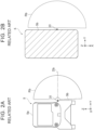
- FIG. 3A is a diagram for description of an example when an object is in close proximity, with regard to the vehicle sensor mounting structure according to the related art.
- FIG. 3A illustrates the object 50 and a blocking range Sb that is a range blocked by the object 50 in the detection range Rb of the close-range LiDAR device 20.
- the object 50 is an object such as a pedestrian, a bicycle, or a motorcycle that is in close proximity to the vehicle 5.
- the object 50 may be a construction pole, a utility pole, or some other structure.
- the entire detection range Rb of the close-range LiDAR device 20 is blocked by the object 50 in close proximity to the vehicle 5.
- FIG. 3B is a diagram for description of an example when an object 50 is in close proximity, with regard to the vehicle sensor mounting structure according to the first embodiment.
- FIG. 3B illustrates the object 50 and a blocking range Sa that is the range blocked by the object 50 in the detection range Ra of the long-range LiDAR device 10.
- the detection range Ra of the long-range LiDAR device 10 is not completely blocked, and accordingly a region on the other side of the object 50 as viewed from the vehicle 1 can be detected. Accordingly, when there is a bicycle or the like, for example, rapidly approaching the vehicle 1 on the other side of the object 50, the long-range LiDAR device 10 can detect the bicycle or the like.
- the mounting height of the long-range LiDAR device 10 from the road surface is not less than 1.8 m, and accordingly the detection range Ra can be suppressed from being greatly blocked even when an object 50 such as a pedestrian comes into close proximity of the vehicle 1.
- the long-range LiDAR device 10 is mounted on the peripheral edge portion of the roof 1a of the vehicle 1 and has the detection range Ra that expands diagonally downward as viewed from the roof 1a. Accordingly, even a narrow-angle long-range LiDAR device 10 that is readily procurable and that has a detection angle of less than 180° can secure an area of a detection range Ra, which is appropriate for detecting an object on the road surface.
- the long-range LiDAR device 10 can detect or recognize the object 50 with precision, by keeping a distance from the object 50 and detecting the object 50 from the peripheral edge portion of the roof 1a of the vehicle 1. Furthermore, according to the vehicle sensor mounting structure of the first embodiment, mounting the close-range LiDAR device 20 is no longer indispensable. Eliminating the need for developing and mounting the close-range LiDAR device 20 enables reduction in costs.
- the long-range LiDAR device 10 has higher intensity per beam than the close-range LiDAR device 20, and accordingly low-reflection objects can be detected as well. Further, the long-range LiDAR device 10 has high resolution, and accordingly even small fallen objects can be easily detected. Further, providing the long-range LiDAR device 10 on the peripheral edge portion of the roof 1a enables the occurrence of blind spots due to the vehicle body shape of the vehicle 1 to be suppressed.
- the vehicle sensor mounting structure according to the second embodiment is different from the first embodiment in that a long-range LiDAR device 11 is mounted on a front side of the vehicle 1.
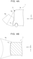
- FIG. 4A is a sideward view of the vehicle, illustrating the vehicle sensor mounting structure according to the second embodiment.
- the long-range LiDAR device 11 is mounted on the forward outer peripheral end of the roof 1a of the vehicle 1.
- the long-range LiDAR device 11 has a detection range Rc that expands diagonally downward as viewed from the roof 1a such that the long-range LiDAR device 11 detects objects in the surroundings of (forward of) the vehicle 1.
- the configuration of the long-range LiDAR device 11 can be the same as that of the long-range LiDAR device 10, for example, and accordingly description thereof will be omitted.
- the definition of a long-range LiDAR device is the same as in the first embodiment.
- the detection range Rc of the long-range LiDAR device 11 is a range from the long-range LiDAR device 11 beyond the lower limit of the detection distance as viewed to the side of the vehicle 1 (in Y-axis direction), and expands in a fan shape centered on a detection axis Dc.
- the detection range Rc includes part of the front face (a part of the outer peripheral face) 1c of the vehicle 1.
- FIG. 4B is a plan view for description of the detection range Rc of the long-range LiDAR device 11 as viewed from above the vehicle. As illustrated in FIG. 4B , the detection range Rc of the long-range LiDAR device 11 broadly covers the range adjacent forward of the vehicle 1.
- a close-range LiDAR device is used in the vehicle sensor mounting structure according to the related art.
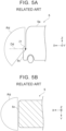
- FIG. 5A is a sideward view of the vehicle, illustrating an example of the vehicle sensor mounting structure according to the related art.
- FIG. 5A illustrates a front face 5c of the vehicle 5, a close-range LiDAR device 21, a detection axis Dd of the close-range LiDAR device 21, and a detection range Rd of the close-range LiDAR device 21.
- the close-range LiDAR device 21 is mounted on the front face 5c of the vehicle 5 in the close-range LiDAR device mounting structure according to the related art.
- the close-range LiDAR device 21 is, for example, the same as that in FIG. 2A in the first embodiment.
- the close-range LiDAR device 21 is mounted, for example, on a bumper portion of the vehicle 5.
- the close-range LiDAR device 21 has the substantially semicircular detection range Rd expanding forward from the vehicle 5.
- the detection range Rd of the close-range LiDAR device 21 does not include the front face 5c of the vehicle 5.
- FIG. 5B is a plan view for description of the detection range Rd of the close-range LiDAR device 21 as viewed from above the vehicle.
- the detection range Rd of the close-range LiDAR device 21 is, as an example, a semicircular range as viewed from above the vehicle.
- FIG. 6A is a diagram for description of an example when an object is in close proximity, with regard to the vehicle sensor mounting structure according to the related art.
- FIG. 6A illustrates an object 60 and a blocking range Sd that is a range blocked by the object 60 in the detection range Rd of the close-range LiDAR device 21.
- the object 60 is the same as the object 50 in the first embodiment.
- FIG. 6B is a diagram for description of an example when the object 60 is in close proximity, with regard to the vehicle sensor mounting structure according to the second embodiment.
- FIG. 6B illustrates the object 60 and a blocking range Sc that is a range blocked by the object 60 in the detection range Rc of the long-range LiDAR device 11.
- the vehicle sensor mounting structure of the second embodiment even when the object 60 such as a pedestrian comes into close proximity of the long-range LiDAR device 11 mounted on a vehicle 1, a greater part of the detection range Rc of the long-range LiDAR device 11 is not blocked, and accordingly the region on the other side of the object 60 as viewed from the vehicle 1 can be detected. Accordingly, when there is a bicycle or the like, for example, rapidly approaching the vehicle 1 on the other side of the object 60, the long-range LiDAR device 11 can detect the bicycle or the like.
- the long-range LiDAR device 10 is mounted on the left side of the vehicle 1, the same advantages can be obtained when the long-range LiDAR device 10 is mounted on the right side of the vehicle 1, as well.
- the long-range LiDAR device 11 is mounted on the front side of the vehicle 1, the same advantages can be obtained when the long-range LiDAR device 11 is mounted on the rear side of the vehicle 1, as well.
- the mounting positions of the long-range LiDAR device 10 and 11 are not limited to the positions illustrated in the drawings either, and may be any position as long as the position is on the peripheral edge portion of the roof 1a of the vehicle 1.
- the detection angle of the long-range LiDAR device 10 and 11 is not limited to less than 180°, and may be a detection angle not less than 180°.
Landscapes
- Engineering & Computer Science (AREA)
- Physics & Mathematics (AREA)
- Mechanical Engineering (AREA)
- Computer Networks & Wireless Communication (AREA)
- General Physics & Mathematics (AREA)
- Radar, Positioning & Navigation (AREA)
- Remote Sensing (AREA)
- Electromagnetism (AREA)
- Optical Radar Systems And Details Thereof (AREA)
Claims (10)
- Structure de montage de capteur de véhicule comprenant :un véhicule (1) ; etun dispositif LiDAR (10, 11) monté sur une partie de bord périphérique d'un toit (la) du véhicule (1),le dispositif LiDAR ayant une plage de détection (Ra, Rc) s'étendant en diagonale vers le bas vue depuis le toit (1a),le dispositif LiDAR étant configuré pour détecter un objet (50, 60) dans une plage de détection (Ra, Rc), et caractérisée en ce quela plage de détection (Ra, Rc) comprend une partie d'une face périphérique extérieure (1b, 1c) d'une carrosserie du véhicule, etle dispositif LiDAR étant un dispositif LiDAR longue portée ayant une limite inférieure de distance de détection qui n'est pas inférieure à 10 cm et pas supérieure à 1 m.
- Structure de montage de capteur de véhicule selon la revendication 1, dans laquelle une hauteur de montage du dispositif LiDAR longue portée (10, 11) n'est pas inférieure à 1,8 m.
- Structure de montage de capteur de véhicule selon la revendication 1 ou 2, dans laquelle un angle de détection du dispositif LiDAR longue portée (10, 11) est inférieur à 180°.
- Structure de montage de capteur de véhicule selon la revendication 1, dans laquelle la partie de bord périphérique du toit (1a) comprend une partie du toit (1a) à une première distance d'une extrémité périphérique extérieure qui est une limite entre le toit (1a) et la face périphérique extérieure (1b, 1c).
- Structure de montage de capteur de véhicule selon la revendication 1, dans laquelle la partie de bord périphérique du toit (1a) comprend une partie de la face périphérique extérieure (1b, 1c) à une deuxième distance à partir d'une extrémité périphérique extérieure qui est une limite entre le toit (1a) et la face périphérique extérieure (1b, 1c).
- Structure de montage de capteur de véhicule selon la revendication 1, dans laquelle l'objet (50,60) comprend un piéton, un vélo ou une moto, à proximité immédiate du véhicule (1).
- Structure de montage de capteur de véhicule selon la revendication 2, dans laquelle la hauteur de montage est une hauteur depuis une surface de route jusqu'à un photorécepteur ou un point central du dispositif LiDAR longue portée (10, 11).
- Structure de montage de capteur de véhicule selon la revendication 2, dans laquelle :le dispositif LiDAR longue portée (10, 11) est monté sur le véhicule (1) par l'intermédiaire d'un support ; etla hauteur de montage qui est une hauteur depuis une surface de route jusqu'à un photorécepteur ou un point central du dispositif LiDAR longue portée (10, 11) monté sur le véhicule (1) via le support n'est pas inférieure à 1,8 m.
- Structure de montage de capteur de véhicule selon l'une quelconque des revendications précédentes, dans laquelle :
la hauteur du véhicule (1) n'est pas inférieure à 1,8 m. - Structure de montage de capteur de véhicule selon l'une quelconque des revendications précédentes, dans laquelle :
le véhicule (1) est un véhicule de type microbus ou un véhicule de type fourgon.
Applications Claiming Priority (1)
| Application Number | Priority Date | Filing Date | Title |
|---|---|---|---|
| JP2021090405A JP2022182704A (ja) | 2021-05-28 | 2021-05-28 | 車両用センサ取り付け構造 |
Publications (3)
| Publication Number | Publication Date |
|---|---|
| EP4095564A2 EP4095564A2 (fr) | 2022-11-30 |
| EP4095564A3 EP4095564A3 (fr) | 2022-12-07 |
| EP4095564B1 true EP4095564B1 (fr) | 2024-12-04 |
Family
ID=81603504
Family Applications (1)
| Application Number | Title | Priority Date | Filing Date |
|---|---|---|---|
| EP22172740.7A Active EP4095564B1 (fr) | 2021-05-28 | 2022-05-11 | Structure de montage de capteur d'un véhicule |
Country Status (4)
| Country | Link |
|---|---|
| US (1) | US20220381883A1 (fr) |
| EP (1) | EP4095564B1 (fr) |
| JP (1) | JP2022182704A (fr) |
| CN (1) | CN115402213B (fr) |
Family Cites Families (24)
| Publication number | Priority date | Publication date | Assignee | Title |
|---|---|---|---|---|
| JPH08122060A (ja) * | 1994-10-21 | 1996-05-17 | Mitsubishi Electric Corp | 車両周辺監視システム |
| JP5213803B2 (ja) * | 2009-07-07 | 2013-06-19 | 日立建機株式会社 | 路肩崩落リスク監視装置及び運搬車両 |
| EP2385013A1 (fr) * | 2010-05-03 | 2011-11-09 | Siemens Aktiengesellschaft | Chariot de manutention doté d'un dispositif destiné à la surveillance de la position d'un produit de transport chargé et procédé destiné à la surveillance de la position d'un produit de transport chargé d'un chariot de manutention |
| CN104360350A (zh) * | 2014-11-14 | 2015-02-18 | 武汉大学 | 用于大比例尺测图的脉冲激光雷达及其方法 |
| DE102015226502A1 (de) * | 2015-12-22 | 2017-06-22 | Robert Bosch Gmbh | Lidar-Abtasteinrichtung an einem Kraftfahrzeug |
| JP2017161363A (ja) * | 2016-03-09 | 2017-09-14 | 株式会社デンソー | 区画線認識装置 |
| JP6421783B2 (ja) * | 2016-04-26 | 2018-11-14 | トヨタ自動車株式会社 | 周辺情報検出センサの配設構造 |
| WO2017200896A2 (fr) * | 2016-05-18 | 2017-11-23 | James O'keeffe | Lidar à orientation dynamique adapté à la forme de véhicule |
| US10488493B2 (en) * | 2016-09-27 | 2019-11-26 | Denso International America, Inc. | Sensor array for autonomous vehicle |
| US10875481B2 (en) | 2017-02-09 | 2020-12-29 | Honda Motor Co., Ltd. | Mounting structure for external environment detection device for vehicle |
| US10509947B1 (en) * | 2017-04-11 | 2019-12-17 | Zoox, Inc. | Converting multi-dimensional data for image analysis |
| CN110537109B (zh) * | 2017-04-28 | 2024-02-20 | 深圳市大疆创新科技有限公司 | 用于自主驾驶的感测组件 |
| US10754033B2 (en) * | 2017-06-30 | 2020-08-25 | Waymo Llc | Light detection and ranging (LIDAR) device range aliasing resilience by multiple hypotheses |
| EP3437930B1 (fr) * | 2017-08-01 | 2021-07-28 | SMR Patents S.à.r.l. | Dispositif de caméra et véhicule automobile comprenant un tel dispositif |
| US10620638B2 (en) * | 2017-08-18 | 2020-04-14 | Wipro Limited | Method, system, and device for guiding autonomous vehicles based on dynamic extraction of road region |
| KR102800559B1 (ko) * | 2018-03-29 | 2025-04-24 | 얀마 파워 테크놀로지 가부시키가이샤 | 장애물 검지 시스템, 및, 작업 차량 |
| US12153163B2 (en) * | 2018-08-03 | 2024-11-26 | OPSYS Tech Ltd. | Distributed modular solid-state lidar system |
| JP7458143B2 (ja) * | 2018-08-28 | 2024-03-29 | ヤンマーパワーテクノロジー株式会社 | 障害物検知システム |
| CN109375635A (zh) * | 2018-12-20 | 2019-02-22 | 安徽江淮汽车集团股份有限公司 | 一种自动驾驶汽车道路环境感知系统及方法 |
| US11391820B2 (en) * | 2019-04-26 | 2022-07-19 | Waymo L LC | Mirrors to extend sensor field of view in self-driving vehicles |
| CN110979194A (zh) * | 2019-12-13 | 2020-04-10 | 天津恒天新能源汽车研究院有限公司 | 一种组合式智能驾驶汽车激光雷达安装支架 |
| CN111693043B (zh) * | 2020-06-18 | 2023-04-07 | 北京四维图新科技股份有限公司 | 地图数据处理方法以及设备 |
| CN112379674B (zh) * | 2020-11-26 | 2022-06-21 | 中国第一汽车股份有限公司 | 一种自动驾驶设备及系统 |
| CN112347999B (zh) * | 2021-01-07 | 2021-05-14 | 深圳市速腾聚创科技有限公司 | 障碍物识别模型训练方法、障碍物识别方法、装置及系统 |
-
2021
- 2021-05-28 JP JP2021090405A patent/JP2022182704A/ja active Pending
-
2022
- 2022-05-11 EP EP22172740.7A patent/EP4095564B1/fr active Active
- 2022-05-20 CN CN202210553810.4A patent/CN115402213B/zh active Active
- 2022-05-23 US US17/750,744 patent/US20220381883A1/en active Pending
Also Published As
| Publication number | Publication date |
|---|---|
| EP4095564A3 (fr) | 2022-12-07 |
| EP4095564A2 (fr) | 2022-11-30 |
| JP2022182704A (ja) | 2022-12-08 |
| CN115402213A (zh) | 2022-11-29 |
| US20220381883A1 (en) | 2022-12-01 |
| CN115402213B (zh) | 2025-08-01 |
Similar Documents
| Publication | Publication Date | Title |
|---|---|---|
| US11796356B2 (en) | Sensor installation structure | |
| US8638205B2 (en) | Device for preventing a collision of a pivoting element of a vehicle | |
| US20200238904A1 (en) | Apparatus, system and method for preventing collision | |
| JP6396838B2 (ja) | 車両制御装置、及び車両制御方法 | |
| EP3941793B1 (fr) | Miroirs pour étendre le champ de vision d'un capteur dans des véhicules autonomes | |
| US10422857B2 (en) | Device for ascertaining a misalignment of a detection unit fastened on a vehicle | |
| EP2302412B1 (fr) | Système et procédé d'évaluation d'une menace de collision avant d'un véhicule automobile | |
| US20050219506A1 (en) | Object recognition device for vehicle | |
| US20180090006A1 (en) | Automotive target-detection system | |
| KR102192252B1 (ko) | 센서를 이용한 차량 인식 시스템 및 그 방법 | |
| JP6332383B2 (ja) | 車両用物標検出システム | |
| CN111736153A (zh) | 用于无人驾驶车辆的环境检测系统、方法、设备和介质 | |
| US20170153329A1 (en) | Object detection apparatus | |
| JP2016192167A (ja) | 車両制御装置、及び車両制御方法 | |
| WO2017138329A1 (fr) | Dispositif de prédiction de collision | |
| KR102172071B1 (ko) | 물체 분류로 자동차의 주변 영역을 포착하는 방법, 제어 장치, 운전자 보조 시스템, 및 자동차 | |
| JP2018054328A (ja) | 鉱山用作業機械及びその障害物検出装置 | |
| EP4095564A2 (fr) | Structure de montage de capteur d'un véhicule | |
| JP3800624B2 (ja) | 自動車の周囲環境を判定するセンサシステム | |
| JPH1027299A (ja) | 車載用レーダ装置 | |
| WO2017138331A1 (fr) | Dispositif de détection d'objets | |
| KR102397360B1 (ko) | 센서 이미지의 주사점에 의해 광전자 센서의 롤 각도를 결정하기 위한 방법, 및 광전자 센서 | |
| US20220206153A1 (en) | Vehicular sensing system and vehicle | |
| WO2021153774A1 (fr) | Dispositif de détection et dispositif de calcul de position de détection | |
| JPS6239520Y2 (fr) |
Legal Events
| Date | Code | Title | Description |
|---|---|---|---|
| PUAI | Public reference made under article 153(3) epc to a published international application that has entered the european phase |
Free format text: ORIGINAL CODE: 0009012 |
|
| STAA | Information on the status of an ep patent application or granted ep patent |
Free format text: STATUS: REQUEST FOR EXAMINATION WAS MADE |
|
| PUAL | Search report despatched |
Free format text: ORIGINAL CODE: 0009013 |
|
| 17P | Request for examination filed |
Effective date: 20220511 |
|
| AK | Designated contracting states |
Kind code of ref document: A2 Designated state(s): AL AT BE BG CH CY CZ DE DK EE ES FI FR GB GR HR HU IE IS IT LI LT LU LV MC MK MT NL NO PL PT RO RS SE SI SK SM TR |
|
| AK | Designated contracting states |
Kind code of ref document: A3 Designated state(s): AL AT BE BG CH CY CZ DE DK EE ES FI FR GB GR HR HU IE IS IT LI LT LU LV MC MK MT NL NO PL PT RO RS SE SI SK SM TR |
|
| RIC1 | Information provided on ipc code assigned before grant |
Ipc: B60R 11/00 20060101ALI20221028BHEP Ipc: G01S 17/931 20200101AFI20221028BHEP |
|
| GRAP | Despatch of communication of intention to grant a patent |
Free format text: ORIGINAL CODE: EPIDOSNIGR1 |
|
| STAA | Information on the status of an ep patent application or granted ep patent |
Free format text: STATUS: GRANT OF PATENT IS INTENDED |
|
| INTG | Intention to grant announced |
Effective date: 20240916 |
|
| GRAS | Grant fee paid |
Free format text: ORIGINAL CODE: EPIDOSNIGR3 |
|
| GRAA | (expected) grant |
Free format text: ORIGINAL CODE: 0009210 |
|
| STAA | Information on the status of an ep patent application or granted ep patent |
Free format text: STATUS: THE PATENT HAS BEEN GRANTED |
|
| AK | Designated contracting states |
Kind code of ref document: B1 Designated state(s): AL AT BE BG CH CY CZ DE DK EE ES FI FR GB GR HR HU IE IS IT LI LT LU LV MC MK MT NL NO PL PT RO RS SE SI SK SM TR |
|
| REG | Reference to a national code |
Ref country code: CH Ref legal event code: EP |
|
| REG | Reference to a national code |
Ref country code: DE Ref legal event code: R096 Ref document number: 602022008307 Country of ref document: DE |
|
| REG | Reference to a national code |
Ref country code: IE Ref legal event code: FG4D |
|
| REG | Reference to a national code |
Ref country code: LT Ref legal event code: MG9D |
|
| REG | Reference to a national code |
Ref country code: NL Ref legal event code: MP Effective date: 20241204 |
|
| PG25 | Lapsed in a contracting state [announced via postgrant information from national office to epo] |
Ref country code: HR Free format text: LAPSE BECAUSE OF FAILURE TO SUBMIT A TRANSLATION OF THE DESCRIPTION OR TO PAY THE FEE WITHIN THE PRESCRIBED TIME-LIMIT Effective date: 20241204 |
|
| PG25 | Lapsed in a contracting state [announced via postgrant information from national office to epo] |
Ref country code: FI Free format text: LAPSE BECAUSE OF FAILURE TO SUBMIT A TRANSLATION OF THE DESCRIPTION OR TO PAY THE FEE WITHIN THE PRESCRIBED TIME-LIMIT Effective date: 20241204 |
|
| PG25 | Lapsed in a contracting state [announced via postgrant information from national office to epo] |
Ref country code: BG Free format text: LAPSE BECAUSE OF FAILURE TO SUBMIT A TRANSLATION OF THE DESCRIPTION OR TO PAY THE FEE WITHIN THE PRESCRIBED TIME-LIMIT Effective date: 20241204 |
|
| PG25 | Lapsed in a contracting state [announced via postgrant information from national office to epo] |
Ref country code: ES Free format text: LAPSE BECAUSE OF FAILURE TO SUBMIT A TRANSLATION OF THE DESCRIPTION OR TO PAY THE FEE WITHIN THE PRESCRIBED TIME-LIMIT Effective date: 20241204 |
|
| PG25 | Lapsed in a contracting state [announced via postgrant information from national office to epo] |
Ref country code: NO Free format text: LAPSE BECAUSE OF FAILURE TO SUBMIT A TRANSLATION OF THE DESCRIPTION OR TO PAY THE FEE WITHIN THE PRESCRIBED TIME-LIMIT Effective date: 20250304 |
|
| PG25 | Lapsed in a contracting state [announced via postgrant information from national office to epo] |
Ref country code: LV Free format text: LAPSE BECAUSE OF FAILURE TO SUBMIT A TRANSLATION OF THE DESCRIPTION OR TO PAY THE FEE WITHIN THE PRESCRIBED TIME-LIMIT Effective date: 20241204 Ref country code: GR Free format text: LAPSE BECAUSE OF FAILURE TO SUBMIT A TRANSLATION OF THE DESCRIPTION OR TO PAY THE FEE WITHIN THE PRESCRIBED TIME-LIMIT Effective date: 20250305 |
|
| PG25 | Lapsed in a contracting state [announced via postgrant information from national office to epo] |
Ref country code: RS Free format text: LAPSE BECAUSE OF FAILURE TO SUBMIT A TRANSLATION OF THE DESCRIPTION OR TO PAY THE FEE WITHIN THE PRESCRIBED TIME-LIMIT Effective date: 20250304 |
|
| PG25 | Lapsed in a contracting state [announced via postgrant information from national office to epo] |
Ref country code: NL Free format text: LAPSE BECAUSE OF FAILURE TO SUBMIT A TRANSLATION OF THE DESCRIPTION OR TO PAY THE FEE WITHIN THE PRESCRIBED TIME-LIMIT Effective date: 20241204 |
|
| REG | Reference to a national code |
Ref country code: AT Ref legal event code: MK05 Ref document number: 1748724 Country of ref document: AT Kind code of ref document: T Effective date: 20241204 |
|
| P01 | Opt-out of the competence of the unified patent court (upc) registered |
Free format text: CASE NUMBER: APP_20536/2025 Effective date: 20250430 |
|
| PG25 | Lapsed in a contracting state [announced via postgrant information from national office to epo] |
Ref country code: SM Free format text: LAPSE BECAUSE OF FAILURE TO SUBMIT A TRANSLATION OF THE DESCRIPTION OR TO PAY THE FEE WITHIN THE PRESCRIBED TIME-LIMIT Effective date: 20241204 |
|
| PG25 | Lapsed in a contracting state [announced via postgrant information from national office to epo] |
Ref country code: PL Free format text: LAPSE BECAUSE OF FAILURE TO SUBMIT A TRANSLATION OF THE DESCRIPTION OR TO PAY THE FEE WITHIN THE PRESCRIBED TIME-LIMIT Effective date: 20241204 |
|
| PGFP | Annual fee paid to national office [announced via postgrant information from national office to epo] |
Ref country code: DE Payment date: 20250319 Year of fee payment: 4 |
|
| PG25 | Lapsed in a contracting state [announced via postgrant information from national office to epo] |
Ref country code: IS Free format text: LAPSE BECAUSE OF FAILURE TO SUBMIT A TRANSLATION OF THE DESCRIPTION OR TO PAY THE FEE WITHIN THE PRESCRIBED TIME-LIMIT Effective date: 20250404 |
|
| PG25 | Lapsed in a contracting state [announced via postgrant information from national office to epo] |
Ref country code: PT Free format text: LAPSE BECAUSE OF FAILURE TO SUBMIT A TRANSLATION OF THE DESCRIPTION OR TO PAY THE FEE WITHIN THE PRESCRIBED TIME-LIMIT Effective date: 20250404 |
|
| PG25 | Lapsed in a contracting state [announced via postgrant information from national office to epo] |
Ref country code: EE Free format text: LAPSE BECAUSE OF FAILURE TO SUBMIT A TRANSLATION OF THE DESCRIPTION OR TO PAY THE FEE WITHIN THE PRESCRIBED TIME-LIMIT Effective date: 20241204 |
|
| PG25 | Lapsed in a contracting state [announced via postgrant information from national office to epo] |
Ref country code: RO Free format text: LAPSE BECAUSE OF FAILURE TO SUBMIT A TRANSLATION OF THE DESCRIPTION OR TO PAY THE FEE WITHIN THE PRESCRIBED TIME-LIMIT Effective date: 20241204 Ref country code: AT Free format text: LAPSE BECAUSE OF FAILURE TO SUBMIT A TRANSLATION OF THE DESCRIPTION OR TO PAY THE FEE WITHIN THE PRESCRIBED TIME-LIMIT Effective date: 20241204 |
|
| PG25 | Lapsed in a contracting state [announced via postgrant information from national office to epo] |
Ref country code: SK Free format text: LAPSE BECAUSE OF FAILURE TO SUBMIT A TRANSLATION OF THE DESCRIPTION OR TO PAY THE FEE WITHIN THE PRESCRIBED TIME-LIMIT Effective date: 20241204 |
|
| PG25 | Lapsed in a contracting state [announced via postgrant information from national office to epo] |
Ref country code: CZ Free format text: LAPSE BECAUSE OF FAILURE TO SUBMIT A TRANSLATION OF THE DESCRIPTION OR TO PAY THE FEE WITHIN THE PRESCRIBED TIME-LIMIT Effective date: 20241204 |
|
| PG25 | Lapsed in a contracting state [announced via postgrant information from national office to epo] |
Ref country code: IT Free format text: LAPSE BECAUSE OF FAILURE TO SUBMIT A TRANSLATION OF THE DESCRIPTION OR TO PAY THE FEE WITHIN THE PRESCRIBED TIME-LIMIT Effective date: 20241204 |
|
| REG | Reference to a national code |
Ref country code: DE Ref legal event code: R097 Ref document number: 602022008307 Country of ref document: DE |
|
| PG25 | Lapsed in a contracting state [announced via postgrant information from national office to epo] |
Ref country code: SE Free format text: LAPSE BECAUSE OF FAILURE TO SUBMIT A TRANSLATION OF THE DESCRIPTION OR TO PAY THE FEE WITHIN THE PRESCRIBED TIME-LIMIT Effective date: 20241204 |
|
| REG | Reference to a national code |
Ref country code: DE Ref legal event code: R084 Ref document number: 602022008307 Country of ref document: DE |
|
| PG25 | Lapsed in a contracting state [announced via postgrant information from national office to epo] |
Ref country code: DK Free format text: LAPSE BECAUSE OF FAILURE TO SUBMIT A TRANSLATION OF THE DESCRIPTION OR TO PAY THE FEE WITHIN THE PRESCRIBED TIME-LIMIT Effective date: 20241204 |
|
| PLBE | No opposition filed within time limit |
Free format text: ORIGINAL CODE: 0009261 |
|
| STAA | Information on the status of an ep patent application or granted ep patent |
Free format text: STATUS: NO OPPOSITION FILED WITHIN TIME LIMIT |
|
| REG | Reference to a national code |
Ref country code: CH Ref legal event code: L10 Free format text: ST27 STATUS EVENT CODE: U-0-0-L10-L00 (AS PROVIDED BY THE NATIONAL OFFICE) Effective date: 20251015 |
|
| 26N | No opposition filed |
Effective date: 20250905 |
|
| REG | Reference to a national code |
Ref country code: CH Ref legal event code: H13 Free format text: ST27 STATUS EVENT CODE: U-0-0-H10-H13 (AS PROVIDED BY THE NATIONAL OFFICE) Effective date: 20251223 |
|
| PG25 | Lapsed in a contracting state [announced via postgrant information from national office to epo] |
Ref country code: LU Free format text: LAPSE BECAUSE OF NON-PAYMENT OF DUE FEES Effective date: 20250511 |
|
| PG25 | Lapsed in a contracting state [announced via postgrant information from national office to epo] |
Ref country code: CH Free format text: LAPSE BECAUSE OF NON-PAYMENT OF DUE FEES Effective date: 20250531 |
|
| REG | Reference to a national code |
Ref country code: BE Ref legal event code: MM Effective date: 20250531 |
|
| PG25 | Lapsed in a contracting state [announced via postgrant information from national office to epo] |
Ref country code: MC Free format text: LAPSE BECAUSE OF FAILURE TO SUBMIT A TRANSLATION OF THE DESCRIPTION OR TO PAY THE FEE WITHIN THE PRESCRIBED TIME-LIMIT Effective date: 20241204 |
|
| PG25 | Lapsed in a contracting state [announced via postgrant information from national office to epo] |
Ref country code: IE Free format text: LAPSE BECAUSE OF NON-PAYMENT OF DUE FEES Effective date: 20250511 |
|
| PG25 | Lapsed in a contracting state [announced via postgrant information from national office to epo] |
Ref country code: BE Free format text: LAPSE BECAUSE OF NON-PAYMENT OF DUE FEES Effective date: 20250531 |
|
| PG25 | Lapsed in a contracting state [announced via postgrant information from national office to epo] |
Ref country code: FR Free format text: LAPSE BECAUSE OF NON-PAYMENT OF DUE FEES Effective date: 20250531 |