EP4096529B1 - Treuil autobloquant - Google Patents
Treuil autobloquant Download PDFInfo
- Publication number
- EP4096529B1 EP4096529B1 EP21714385.8A EP21714385A EP4096529B1 EP 4096529 B1 EP4096529 B1 EP 4096529B1 EP 21714385 A EP21714385 A EP 21714385A EP 4096529 B1 EP4096529 B1 EP 4096529B1
- Authority
- EP
- European Patent Office
- Prior art keywords
- spool
- tether
- winch
- mount
- rotation axis
- Prior art date
- Legal status (The legal status is an assumption and is not a legal conclusion. Google has not performed a legal analysis and makes no representation as to the accuracy of the status listed.)
- Active
Links
Images









Classifications
-
- A—HUMAN NECESSITIES
- A61—MEDICAL OR VETERINARY SCIENCE; HYGIENE
- A61B—DIAGNOSIS; SURGERY; IDENTIFICATION
- A61B17/00—Surgical instruments, devices or methods
- A61B17/04—Surgical instruments, devices or methods for suturing wounds; Holders or packages for needles or suture materials
- A61B17/0401—Suture anchors, buttons or pledgets, i.e. means for attaching sutures to bone, cartilage or soft tissue; Instruments for applying or removing suture anchors
-
- A—HUMAN NECESSITIES
- A61—MEDICAL OR VETERINARY SCIENCE; HYGIENE
- A61B—DIAGNOSIS; SURGERY; IDENTIFICATION
- A61B17/00—Surgical instruments, devices or methods
- A61B17/064—Surgical staples, i.e. penetrating the tissue
-
- A—HUMAN NECESSITIES
- A61—MEDICAL OR VETERINARY SCIENCE; HYGIENE
- A61B—DIAGNOSIS; SURGERY; IDENTIFICATION
- A61B17/00—Surgical instruments, devices or methods
- A61B17/04—Surgical instruments, devices or methods for suturing wounds; Holders or packages for needles or suture materials
- A61B17/0493—Protective devices for suturing, i.e. for protecting the patient's organs or the operator
-
- A—HUMAN NECESSITIES
- A61—MEDICAL OR VETERINARY SCIENCE; HYGIENE
- A61B—DIAGNOSIS; SURGERY; IDENTIFICATION
- A61B17/00—Surgical instruments, devices or methods
- A61B17/068—Surgical staplers, e.g. containing multiple staples or clamps
-
- A—HUMAN NECESSITIES
- A61—MEDICAL OR VETERINARY SCIENCE; HYGIENE
- A61B—DIAGNOSIS; SURGERY; IDENTIFICATION
- A61B17/00—Surgical instruments, devices or methods
- A61B17/04—Surgical instruments, devices or methods for suturing wounds; Holders or packages for needles or suture materials
- A61B17/06—Needles ; Sutures; Needle-suture combinations; Holders or packages for needles or suture materials
- A61B17/06114—Packages or dispensers for needles or sutures
- A61B17/06119—Packages or dispensers for needles or sutures of cylindrical shape
-
- A—HUMAN NECESSITIES
- A61—MEDICAL OR VETERINARY SCIENCE; HYGIENE
- A61B—DIAGNOSIS; SURGERY; IDENTIFICATION
- A61B17/00—Surgical instruments, devices or methods
- A61B2017/00743—Type of operation; Specification of treatment sites
- A61B2017/00778—Operations on blood vessels
- A61B2017/00783—Valvuloplasty
-
- A—HUMAN NECESSITIES
- A61—MEDICAL OR VETERINARY SCIENCE; HYGIENE
- A61B—DIAGNOSIS; SURGERY; IDENTIFICATION
- A61B17/00—Surgical instruments, devices or methods
- A61B17/04—Surgical instruments, devices or methods for suturing wounds; Holders or packages for needles or suture materials
- A61B17/0401—Suture anchors, buttons or pledgets, i.e. means for attaching sutures to bone, cartilage or soft tissue; Instruments for applying or removing suture anchors
- A61B2017/0409—Instruments for applying suture anchors
-
- A—HUMAN NECESSITIES
- A61—MEDICAL OR VETERINARY SCIENCE; HYGIENE
- A61B—DIAGNOSIS; SURGERY; IDENTIFICATION
- A61B17/00—Surgical instruments, devices or methods
- A61B17/04—Surgical instruments, devices or methods for suturing wounds; Holders or packages for needles or suture materials
- A61B17/0401—Suture anchors, buttons or pledgets, i.e. means for attaching sutures to bone, cartilage or soft tissue; Instruments for applying or removing suture anchors
- A61B2017/044—Suture anchors, buttons or pledgets, i.e. means for attaching sutures to bone, cartilage or soft tissue; Instruments for applying or removing suture anchors with a threaded shaft, e.g. screws
- A61B2017/0441—Suture anchors, buttons or pledgets, i.e. means for attaching sutures to bone, cartilage or soft tissue; Instruments for applying or removing suture anchors with a threaded shaft, e.g. screws the shaft being a rigid coil or spiral
-
- A—HUMAN NECESSITIES
- A61—MEDICAL OR VETERINARY SCIENCE; HYGIENE
- A61B—DIAGNOSIS; SURGERY; IDENTIFICATION
- A61B17/00—Surgical instruments, devices or methods
- A61B17/04—Surgical instruments, devices or methods for suturing wounds; Holders or packages for needles or suture materials
- A61B17/0401—Suture anchors, buttons or pledgets, i.e. means for attaching sutures to bone, cartilage or soft tissue; Instruments for applying or removing suture anchors
- A61B2017/0464—Suture anchors, buttons or pledgets, i.e. means for attaching sutures to bone, cartilage or soft tissue; Instruments for applying or removing suture anchors for soft tissue
-
- A—HUMAN NECESSITIES
- A61—MEDICAL OR VETERINARY SCIENCE; HYGIENE
- A61B—DIAGNOSIS; SURGERY; IDENTIFICATION
- A61B17/00—Surgical instruments, devices or methods
- A61B17/04—Surgical instruments, devices or methods for suturing wounds; Holders or packages for needles or suture materials
- A61B2017/0496—Surgical instruments, devices or methods for suturing wounds; Holders or packages for needles or suture materials for tensioning sutures
-
- A—HUMAN NECESSITIES
- A61—MEDICAL OR VETERINARY SCIENCE; HYGIENE
- A61F—FILTERS IMPLANTABLE INTO BLOOD VESSELS; PROSTHESES; DEVICES PROVIDING PATENCY TO, OR PREVENTING COLLAPSING OF, TUBULAR STRUCTURES OF THE BODY, e.g. STENTS; ORTHOPAEDIC, NURSING OR CONTRACEPTIVE DEVICES; FOMENTATION; TREATMENT OR PROTECTION OF EYES OR EARS; BANDAGES, DRESSINGS OR ABSORBENT PADS; FIRST-AID KITS
- A61F2/00—Filters implantable into blood vessels; Prostheses, i.e. artificial substitutes or replacements for parts of the body; Appliances for connecting them with the body; Devices providing patency to, or preventing collapsing of, tubular structures of the body, e.g. stents
- A61F2/02—Prostheses implantable into the body
- A61F2/24—Heart valves ; Vascular valves, e.g. venous valves; Heart implants, e.g. passive devices for improving the function of the native valve or the heart muscle; Transmyocardial revascularisation [TMR] devices; Valves implantable in the body
- A61F2/2442—Annuloplasty rings or inserts for correcting the valve shape; Implants for improving the function of a native heart valve
Definitions
- Dilation of the annulus of a heart valve prevents the valve leaflets from fully coapting when the valve is closed. Regurgitation of blood from the ventricle into the atrium results in increased total stroke volume and decreased cardiac output, and ultimate weakening of the ventricle secondary to a volume overload and a pressure overload of the atrium.
- US 2010/0280604 describes apparatus that includes an implant structure, which includes a contracting mechanism, which includes a rotatable structure, arranged such that rotation of the rotatable structure contracts the implant structure.
- a longitudinal member is coupled to the contracting mechanism.
- a tool for rotating the rotatable structure is configured to be guided along the longitudinal member, to engage the rotatable structure and to rotate the rotatable structure in response to a rotational force applied to the tool.
- Some applications of the present invention and disclosure are directed to systems, apparatuses, and methods for adjusting a medical implant using an adjustment mechanism.
- the adjustment mechanism can comprise a winch.
- adjustment is achieved by using the winch to apply tension to a tether, the tether extending away from the winch toward an end portion.
- the winch can comprise a spool coupled to the tether.
- the winch can be fixedly coupled to a mount having a driver interface, such that such that driving of the driver interface by a driver rotates the mount about a rotation axis, drawing the end portion of the tether toward the spool by winding the tether around the spool axis of the spool.
- the spool can be coupled to the mount in a position and an orientation with respect to the rotation axis that facilitates the spool drawing the end portion of the tether toward the winch by winding of the tether around the spool in response to rotation of the mount in a forward rotational direction about the rotation axis. Further, the spool can be coupled to the mount in a position and an orientation with respect to the rotation axis that inhibits unwinding of the tether from the spool in response to pulling of the end portion away from the spool, by inhibiting the pulling from rotating the mount in a reverse rotational direction about the rotation axis.
- the position and orientation of the spool facilitate the spool drawing the end portion of the tether toward the winch by winding of the tether around the spool in response to forward rotation of the mount about the rotation axis
- this position and orientation typically inhibit pulling of the end portion away from the spool from causing reverse rotation of the mount and unwinding of the tether from the spool.
- the spool (e.g., a spool axis defined by the spool) is not coaxial with the rotation axis.
- the spool can be disposed laterally from (e.g., parallel with) the rotation axis.
- the spool is entirely disposed laterally form the rotation axis, e.g., such that upon rotation of the mount about the rotation axis, the spool revolves around the rotation axis.
- the spool can be orthogonal to the rotation axis, e.g., such that the rotation axis passes through the spool, e.g., such that upon rotation of the mount about the rotation axis, the spool rotates about the rotation axis in a manner similar to that of a propeller on its axle.
- the adjustment mechanism includes at least one inclined guide coupled to the mount and disposed laterally from the rotation axis.
- the inclined guide can be positioned such that, upon rotation of the mount in the forward rotational direction, the guide guides the tether around the spool.
- driving of the driver interface by the driver moves the guide, with the mount, about the rotation axis.
- the adjustment mechanism includes a housing that houses the winch and is configured to facilitate rotation of the mount about the rotation axis with respect to the housing, the spool moving with the mount.
- the housing can define an aperture configured to facilitate passage of the tether from outside the winch to the spool as the spool draws the end portion of the tether toward the winch.
- the adjustment mechanism comprises at least one flange, configured to provide mechanical separation between the tether and the driver interface.
- the winch includes an eyelet that defines an aperture therethrough.
- the aperture can be configured to facilitate passage of the tether from outside the winch to the spool as the spool draws the end portion of the tether toward the winch.
- the eyelet is mechanically engaged with the guide such that, upon rotation of the mount in the forward rotational direction, the inclined guide guides the tether around the spool by moving the eyelet longitudinally, parallel with the rotation axis, e.g., along a track, such as a track defined by the housing.
- At least one anchor is used to anchor the end portion of the tether to tissue of a subject.
- Some such applications include an annuloplasty structure that is configured such that the drawing of the end portion of the tether from the anchor toward the winch reduces a length of the structure.
- the annuloplasty structure can comprise a longitudinal flexible sleeve defining an elongate lumen, coupled to the winch, and having a contracting portion along which the tether extends. Drawing of the end portion of the tether toward the winch can longitudinally contract the contracting portion.
- a system and/or an apparatus for use with a transcatheterally-advanceable driver including an implant.
- the implant can include a tether, having an end portion and a winch.
- the winch includes a driver interface, engageable and drivable by the driver and a mount, coupled to the driver interface such that driving of the driver interface by the driver rotates the mount about a rotation axis.
- the winch includes a spool coupled to the tether, the tether extending away from the winch toward the end portion and is fixedly coupled to the mount in a position and an orientation with respect to the rotation axis.
- the position and the orientation facilitate the spool drawing the end portion of the tether toward the winch by winding of the tether around the spool in response to rotation of the mount in a forward rotational direction about the rotation axis; and inhibiting unwinding of the tether from the spool in response to pulling of the end portion away from the spool, by inhibiting the pulling from rotating the mount in a reverse rotational direction about the rotation axis.
- the spool is fixedly coupled to the mount such that the spool is entirely disposed laterally from the rotation axis.
- the spool is shaped to define an eye therethrough, the tether being threaded through the eye.
- the spool is fixedly coupled to the mount in a position and an orientation that provides at least one stable rotational orientation of the mount at which the pulling is inhibited from rotating the mount in the reverse rotational direction about the rotation axis. In an application, the spool is fixedly coupled to the mount in a position and an orientation that provides exactly one stable rotational orientation of the mount at which the pulling is inhibited from rotating the mount in the reverse rotational direction about the rotation axis.
- the spool is fixedly coupled to the mount in a position and an orientation that provides at least two stable rotational orientations of the mount at which pulling is inhibited from rotating the mount in the reverse rotational direction about the rotation axis. In an application, the spool is fixedly coupled to the mount in a position and an orientation that provides exactly two stable rotational orientations of the mount at which pulling is inhibited from rotating the mount in the reverse rotational direction about the rotation axis.
- the winch includes at least one flange, the flange configured to provide mechanical separation between the tether and the driver interface.
- the mount is shaped to define the at least one flange.
- the position and the orientation inhibit unwinding of the tether from the spool in response to the pulling by limiting, to less than 180 degrees of reverse rotation, the rotation of the mount in the reverse rotational direction in response to the pulling. In an application, the position and the orientation inhibit unwinding of the tether from the spool in response to the pulling by limiting, to less than 90 degrees of reverse rotation, the rotation of the mount in the reverse rotational direction in response to the pulling. In an application, the position and the orientation inhibit unwinding of the tether from the spool in response to the pulling by limiting, to less than 45 degrees of reverse rotation, the rotation of the mount in the reverse rotational direction in response to the pulling.
- the system/apparatus includes a housing that houses the winch, the housing configured to facilitate movement of the mount and the spool about the rotation axis, with respect to the housing.
- the housing defines an aperture, the aperture configured to facilitate passage of the tether from outside the winch to the spool as the spool draws the end portion of the tether toward the winch.
- the driver interface is accessible to the driver while the winch is housed within the housing.
- the housing is shaped to define an aperture, and the tether extends from the spool, out of the winch via the aperture, and away from the winch toward the end portion.
- the aperture defined by the housing is a circular aperture.
- the aperture defined by the housing is an elongate aperture.
- the elongate aperture has a long axis that is disposed on an aperture plane that is transverse to the rotation axis.
- the implant further includes at least one anchor configured to anchor the end portion of the tether to tissue of a subject.
- the at least one anchor includes a plurality of anchors
- the tether is slidable with respect to at least one of the anchors
- the winch is configured such that drawing the end portion of the tether toward the winch in response to rotation of the mount in the forward rotational direction causes at least one of the anchors to slide distally with respect to the tether.
- the implant includes an annuloplasty structure, and is configured such that the drawing of the end portion of the tether toward the winch reduces a length of the structure.
- the annuloplasty structure includes a longitudinal flexible sleeve: defining an elongate lumen, coupled to the winch, anchorable by the anchor to the tissue, such that the tether is anchored to the tissue by the sleeve being anchored to the tissue, and having a contracting portion along which the tether extends.
- the system/apparatus is configured such that the drawing of the end portion of the tether toward the winch longitudinally contracts the contracting portion.
- the sleeve is coupled to the winch by stitches.
- the winch is coupled to an outer, lateral surface of the sleeve.
- a first portion of the tether extends along the contracting portion; and a second portion of the tether: exits the sleeve at an exit point and is coupled to the winch.
- the system/apparatus includes a delivery tool for delivering the implant to a body of a subject, the delivery tool including a catheter, a distal portion of the catheter being advanceable into the body of the subject.
- the catheter is a steerable transluminal catheter.
- the system/apparatus includes the driver and a guide member, and in a delivery state of the system/apparatus: the implant is disposed at the distal portion of the catheter, and the guide member is coupled to the winch, and extends from the winch proximally through the catheter, to a proximal portion of the catheter, and the driver is slidable over and along the guide member.
- the spool is fixedly coupled to the mount laterally from the rotation axis, such that, in a cross-section of the winch orthogonal to the rotation axis, a radius of the winch: extends radially outward from the rotation axis toward the spool, reaches the spool at a first surface point of the spool, passes through the spool, and passes out of the spool at a second surface point of the spool.
- the spool in the cross-section, has a cross-sectional shape that is a trapezoid. In an application, in the cross-section, the spool has a cross-sectional shape that is a D-shape. In an application, the spool is shaped to define a spool axis, the spool axis being parallel with the rotation axis.
- the first surface point of the spool is a closest point of the spool to the rotation axis. In an application, in the cross-section, the first surface point of the spool is at least 0.2 mm from the rotation axis. In an application, in the cross-section, the first surface point of the spool is 0.2-4 mm from the rotation axis. In an application, in the cross-section, the first surface point of the spool is 0.3-2 mm from the rotation axis.
- the spool is fixedly coupled to the mount orthogonally to the rotation axis.
- the winch includes at least one inclined guide coupled to the mount, disposed laterally from the rotation axis, and positioned such that, upon rotation of the mount in the forward rotational direction, the at least one inclined guide guides the tether around the spool.
- the at least one inclined guide is fixedly coupled to the mount such that, upon driving of the driver interface by the driver, the at least one inclined guide moves with the mount about the rotation axis.
- the at least one inclined guide defines a guide surface that extends helically around and along the rotation axis.
- the at least one inclined guide includes a first inclined guide and a second inclined guide
- the first inclined guide is positioned such that, upon rotation of the mount in the forward rotational direction, the first inclined guide guides the tether to a second side of the spool
- the second inclined guide is positioned such that, upon rotation of the mount in the forward rotational direction, the second inclined guide guides the tether to a first side of the spool that is opposite the second side of the spool.
- the winch defines a first shoulder at which the first inclined guide is coupled to a first end of the spool, and a second shoulder at which the second inclined guide is coupled to a second end of the spool, the first inclined guide is positioned such that, upon rotation of the mount in the forward rotational direction, the first inclined guide guides the tether over the first shoulder to the second side of the spool, and the second inclined guide is positioned such that, upon rotation of the mount in the forward rotational direction, the second inclined guide guides the tether over the second shoulder to the first side of the spool.
- the winch further includes an eyelet that defines an aperture therethrough, the aperture configured to facilitate passage of the tether from outside the winch to the spool as the spool draws the end portion of the tether toward the winch, the eyelet mechanically engaged with the guide such that, upon rotation of the mount in the forward rotational direction, the at least one inclined guide guides the tether around the spool by moving the eyelet longitudinally, parallel with the rotation axis.
- the system/apparatus includes a housing that houses the winch, the housing configured to facilitate movement of the mount and the spool about the rotation axis, with respect to the housing.
- the housing defines a longitudinal track along a track axis, parallel with the rotation axis, the track configured to facilitate, upon rotation of the mount in the forward rotational direction, longitudinal movement of the eyelet along the track axis.
- the driver interface is accessible to the driver while the winch is housed within the housing.
- a system and/or an apparatus for use with a transcatheterally-advanceable driver including an implant, the implant including: a tether, having an end portion; and a winch.
- the winch includes a driver interface, engageable and drivable by the driver, and a mount, coupled to the driver interface such that driving of the driver interface by the driver rotates the mount about a rotation axis.
- the winch includes a spool: defining a spool axis, coupled to the tether, the tether extending away from the winch toward the end portion.
- the spool can be fixedly coupled to the mount such that: rotation of the mount about the rotation axis draws the end portion of the tether toward the spool by winding the tether around the spool axis of the spool, and the spool axis is non-coaxial with the rotation axis.
- the spool is fixedly coupled to the mount such that the spool is entirely disposed laterally from the rotation axis.
- the spool axis is parallel with the rotation axis.
- the spool is shaped to define an eye therethrough, the tether being threaded through the eye.
- the winch includes at least one flange, the flange configured to provide mechanical separation between the tether and the driver interface.
- the mount is shaped to define the at least one flange.
- the system/apparatus includes a housing that houses the winch, the housing configured to facilitate movement of the mount and the spool about the rotation axis, with respect to the housing.
- the driver interface is accessible to the driver while the winch is housed within the housing.
- the housing is shaped to define an aperture
- the tether extends from the spool, out of the winch via the aperture, and away from the winch toward the end portion, and the aperture configured to facilitate passage of the tether into the winch as the spool draws the end portion of the tether toward the winch.
- the housing defines the aperture as circular in shape. In an application, the housing defines the aperture as elongate in shape.
- the housing defines the aperture to have a long axis that is disposed on an aperture plane that is transverse to the rotation axis.
- the implant further includes at least one anchor configured to anchor the end portion of the tether to tissue of a subject.
- the at least one anchor includes a plurality of anchors
- the tether is slidable with respect to at least one of the anchors
- the winch is configured such that drawing the end portion of the tether toward the winch in response to rotation of the mount in the forward rotational direction causes at least one of the anchors to slide distally with respect to the tether.
- the implant includes an annuloplasty structure, and is configured such that the drawing of the end portion of the tether toward the winch reduces a length of the structure.
- the annuloplasty structure includes a longitudinal flexible sleeve: defining an elongate lumen, coupled to the winch, and having a contracting portion along which the tether extends, and the system/apparatus is configured such that the drawing of the end portion of the tether toward the winch longitudinally contracts the contracting portion.
- the sleeve is coupled to the winch by stitches.
- the winch is coupled to an outer, lateral surface of the sleeve.
- a first portion of the tether extends along the contracting portion; and a second portion of the tether: exits the sleeve at an exit point and is coupled to the winch.
- the system/apparatus includes a delivery tool for delivering the implant to a body of a subject, the delivery tool including a catheter, a distal portion of the catheter being advanceable into the body of the subject.
- the catheter is a steerable transluminal catheter.
- the system/apparatus includes the driver and a guide member, and in a delivery state of the system/apparatus: the implant is disposed at the distal portion of the catheter, and the guide member is coupled to the winch, and extends from the winch proximally through the catheter, to a proximal portion of the catheter, and the driver is slidable over and along the guide member.
- the spool is fixedly coupled to the mount laterally from the rotation axis, such that, in a cross-section of the winch orthogonal to the rotation axis, a radius of the winch: extends radially outward from the rotation axis toward the spool, reaches the spool at a first surface point of the spool, passes through the spool, and passes out of the spool at a second surface point of the spool.
- the spool in the cross-section, has a cross-sectional shape that is a trapezoid. In an application, in the cross-section, the spool has a cross-sectional shape that is a D-shape.
- the first surface point of the spool is a closest point of the spool to the rotation axis. In an application, in the cross-section, the first surface point of the spool is at least 0.2 mm from the rotation axis. In an application, in the cross-section, the first surface point of the spool is 0.2-4 mm from the rotation axis. In an application, in the cross-section, the first surface point of the spool is 0.3-2 mm from the rotation axis.
- the spool is fixedly coupled to the mount orthogonally to the rotation axis.
- the winch includes at least one inclined guide coupled to the mount, disposed laterally from the rotation axis, and positioned such that, upon rotation of the mount in the forward rotational direction, the at least one inclined guide guides the tether around the spool.
- the at least one inclined guide is fixedly coupled to the mount such that, upon driving of the driver interface by the driver, the at least one inclined guide moves with the mount about the rotation axis.
- the at least one inclined guide defines a guide surface that extends helically around and along the rotation axis.
- the at least one inclined guide includes a first inclined guide and a second inclined guide
- the first inclined guide is positioned such that, upon rotation of the mount in the forward rotational direction, the first inclined guide guides the tether to a second side of the spool
- the second inclined guide is positioned such that, upon rotation of the mount in the forward rotational direction, the second inclined guide guides the tether to a first side of the spool that is opposite the second side of the spool.
- the winch defines a first shoulder at which the first inclined guide is coupled to a first end of the spool, and a second shoulder at which the second inclined guide is coupled to a second end of the spool, the first inclined guide is positioned such that, upon rotation of the mount in the forward rotational direction, the first inclined guide guides the tether over the first shoulder to the second side of the spool, and the second inclined guide is positioned such that, upon rotation of the mount in the forward rotational direction, the second inclined guide guides the tether over the second shoulder to the first side of the spool.
- the system/apparatus includes an eyelet that defines an aperture therethrough, the aperture configured to facilitate passage of the tether from outside the winch to the spool as the spool draws the end portion of the tether toward the winch, the eyelet mechanically engaged with the guide such that, upon rotation of the mount in the forward rotational direction, the at least one inclined guide guides the tether around the spool by moving the eyelet longitudinally, parallel with the rotation axis.
- the system/apparatus includes a housing that houses the winch, the housing configured to facilitate movement of the mount and the spool about the rotation axis, with respect to the housing.
- the housing defines a longitudinal track along a track axis, parallel with the rotation axis, the track configured to facilitate, upon rotation of the mount in the forward rotational direction, longitudinal movement of the eyelet along the track axis.
- the driver interface is accessible to the driver while the winch is housed within the housing.
- a method including: transcatheterally delivering an implant to tissue of a subject, the implant including a tether, having an end portion and a winch.
- the winch includes a driver interface and a mount, coupled to the driver interface such that driving of the driver interface rotates the mount about a rotation axis.
- the winch includes a spool: defining a spool axis that is non-coaxial with the rotation axis, coupled to the tether, the tether extending away from the winch toward the end portion, and fixedly coupled to the mount. For some applications, drawing the end portion of the tether toward the spool by winding the tether around the spool axis that is non-coaxial with the rotation axis by rotating the mount about the rotation axis.
- the spool axis is parallel with the rotation axis
- winding the tether around the spool axis includes winding the tether around the spool axis that is parallel with the rotation axis.
- the spool axis that is orthogonal to the rotation axis and winding the tether around the spool axis includes winding the tether around the spool axis that is orthogonal to the rotation axis.
- the method includes engaging the driver interface with a driver and rotating the mount about the rotation axis includes rotating the mount about the rotation axis by driving the driver interface with the driver.
- the method includes, subsequently to transcatheterally delivering the implant to the tissue of the subject, and prior to engaging the driver interface with the driver, transcatheterally advancing the driver to the driver interface.
- This method can be performed on a simulation, such as on a cadaver, cadaver heart, simulator (e.g. with the body parts, tissue, etc. being simulated), etc.
- a method including transcatheterally delivering an implant to tissue of a subject, the implant including: a tether, having an end portion; and a winch that includes a driver interface and a mount.
- the winch can also include a spool defining a spool axis.
- the method includes engaging the driver interface with a driver.
- the method includes using the driver, tensioning the tether by winding the tether toward the winch by rotating the mount in a forward rotational direction about a rotation axis.
- the method includes disengaging the driver from the driver interface such that the mount is inhibited from rotating in a reverse rotational direction about the rotation axis in response to pulling from the tensioned tether.
- the spool axis is parallel with the rotation axis
- winding the tether toward the winch includes winding the tether around the spool axis that is parallel with the rotation axis.
- the spool axis that is orthogonal to the rotation axis, and winding the tether toward the winch includes winding the tether around the spool axis that is orthogonal to the rotation axis.
- the method includes, subsequently to transcatheterally delivering the implant to the tissue of the subject, and prior to engaging the driver interface with the driver, transcatheterally advancing the driver to the driver interface.
- This method can be performed on a simulation, such as on a cadaver, cadaver heart, simulator (e.g. with the body parts, tissue, etc. being simulated), etc.
- winch 10 comprises a spool 12 to which a tether 14, comprising an elongate member (e.g. a wire, a ribbon, a rope, a cable, a thread, a filament, etc.) is affixed.
- a tether 14 comprising an elongate member (e.g. a wire, a ribbon, a rope, a cable, a thread, a filament, etc.) is affixed.
- Winch 10 can further comprise a mount 16 to which spool 12 is fixedly attached, such that both the mount and the spool rotate together about a common rotation axis d18. In this way, and as shown in Fig. 1B , rotation of the mount and spool (indicated by solid arrow) about axis d18 winds tether 14 into the winch (indicated by a broken arrow), the tether winding around spool 12.
- mount 16 and spool 12 are coaxial.
- a pulling force applied to a distal end of tether 14 pulls the tether out of the winch, due to the pulling force rotating spool 12 in a reverse rotational direction (indicated by dotted arrow), in a direction opposite of that which accompanied winding of the tether about the spool, such that the tether unwinds from the spool.
- a reverse rotational direction indicated by dotted arrow
- the direction of rotation of a winch that results in unwinding of the tether from about the spool is defined as "reverse rotation.”
- Fig. 2A shows a prior art solution for this, in which a locking mechanism 20 is incorporated into winch 10, resulting in a winch 10b.
- locking mechanism 20 can comprise a ratchet 22 and a pawl 24 affixed to mount 16.
- ratchet 22 is affixed to mount 16 in a manner which enables rotational movement of both the mount and spool 12, about axis d18.
- ratchet 22 can be shaped to define teeth 26, and pawl 24 is shaped to complimentarily fit teeth 26 of the ratchet.
- Pawl 24 can be biased (e.g., by a spring) to engage ratchet 22, such that pawl abuts successive teeth 26 of the ratchet, as the ratchet rotates. Due to the shape of teeth 26 and pawl 24, rotation of spool 12 in the forward direction (counter-clockwise, in Fig. 2A ) results in the sliding of the pawl from a brake zone 28a of a first tooth 26, along a ramp zone 30 of a second tooth, to a brake zone 28b of the second tooth.
- locking mechanism 20 enables rotation of spool (solid arrow in Fig. 2B ) about axis d18, accompanied by winding of tether 14 (dotted arrow in Fig. 2B ).
- spool 12 is largely prevented from rotating in the reverse direction (dotted arrow in Fig. 2C ). That is, the pulling force pulls the spool in the reverse direction such that pawl 24 generally crosses a portion of a ramp zone 30, until the pawl abuts a brake zone 28, ceasing backward rotation of winch 10.
- tether 14 can unwind for less than the rotational length of a tooth 26, until the static abutment of pawl 24 against brake zone 28 prevents the tether from unwinding further. That is, locking mechanism 20 inhibits unwinding of tether 14 from spool 12 in response to pulling of the end portion of the tether away from the spool, by providing winch 10 with unidirectionality.
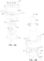
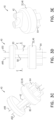
- FIGS. 3A-E , 4A-C are schematic illustrations showing an adjustment mechanism 36 comprising a winch 40, in accordance with some applications.
- winch 40 comprises a mount 46, a spool 42, and a driver interface 64.
- engaging and driving of the driver interface by a transcatheterally-advanceable driver 66 rotates mount 46 about a rotation axis d48 of the winch.
- Spool 42 is generally shaped to define a longitudinal spool axis d50.
- spool 42 is not coaxial with rotation axis d48. Instead, and as described in more detail hereinbelow, spool 42 is disposed laterally from axis d48.
- winch 40 in response to rotation in a forward rotational direction, tether 44 is drawn into the winch and is wound around spool 42.
- the position and orientation at which spool 42 is coupled to mount 46 inhibits subsequent unwinding of tether 44 from the spool in response to pulling of the end portion away from the spool. That is, the position and orientation at which spool 42 is coupled to mount 46 at least in part obviates a need for adjustment mechanism 36 to comprise a discrete locking mechanism (e.g., a discrete actuatable locking mechanism). It is to be noted that, despite this, winch 40 is bidirectionally rotational by driver 66.
- adjustment mechanism 36 further comprises a housing 68 in which the winch is housed, such that mount 46 rotates about axis d48 with respect to the housing.
- housing 68 is shaped to define an aperture 90, and tether 44 extends from spool 42, out of winch 40 via the aperture, and away from the winch toward end portion 62.
- aperture 90 is shaped to define an elongate shape, a long axis thereof being disposed on an aperture plane d38 that is transverse to spool axis d50.
- driver interface 64 can be accessible to driver 66 from outside of the housing.
- Tether 44 (e.g., a proximal end thereof) is fixedly attached (e.g. tied, crimped, soldered, brazed or welded) to spool 42.
- spool 42 is shaped to define an eye 80 that is configured to facilitate this affixation.
- winch 40 further comprises at least one flange 32, e.g., two flanges 32, one at each end of spool 42 (e.g., abutting the spool).
- flanges 32 are defined by and/or are integral with mount 46.
- flange 32 is shaped to provide mechanical separation between spool 42 and driver interface 64. It is therefore hypothesized that flange 32 inhibits tether 44 from slipping off of spool 42 and/or becoming trapped between elements of the adjustment mechanism.
- tether 44 in response to rotation of mount 46 in its forward rotational direction (solid arrow in Fig. 4A ), tether 44 is drawn into the winch (broken arrow in Fig. 4A ), and is wound around spool 42 - e.g., as shown by the transition between Fig. 4A and 4B .
- the position and orientation at which spool 42 is coupled to mount 46 inhibits subsequent unwinding of tether 44 from the spool (represented by the absence of a rotational arrow in Fig. 4C ) in response to pulling of tether 44 away from the spool (solid arrow in Fig. 4C ).
- pulling tether 44 does not rotate mount 46 in a reverse rotational direction about the rotation axis. In fact, in certain rotational positions of mount 46, pulling tether 44 rotates the mount a little further in the forward rotational orientation (e.g., as shown by the transition between Fig. 4B and 4C ), e.g., until the winch reaches a stable rotational orientation.
- Figs. 4B and Fig. 4C illustrate transition of winch 40 from a dynamic rotational position ( Fig. 4B ) to a stable rotational orientation ( Fig. 4C ).
- the pulling force solid arrow
- the pulling force rotates spool 42 in the forward rotational direction, until it reaches the stable rotational orientation shown in Fig. 4C .
- winch 40 assumes its stable rotational orientation, further pulling of the tether does not: (i) unwind tether 44 from spool 42 in response to pulling of tether 44 away from the spool, nor (ii) rotate mount 46 about the rotation axis.
- the stable rotational orientation that provides resistance to unwinding in response to pulling of the tether results from the position and orientation at which spool 42 is coupled to mount 46.
- spool 42 is disposed laterally from axis d48, e.g., with spool axis d50 being non-coaxial with rotation axis d48.
- spool axis d50 can be parallel to rotation axis d48.
- spool 42 is entirely disposed laterally from the rotation axis. That is, a radius d52 of the winch extends radially outward from axis d48 toward spool 42, reaches spool 42 at a first surface point 54, passes through the spool, and passes out of the spool at a second surface point 56.
- spool 42 defines two opposing sides: (i) a first side 58 that includes surface point 54 and faces axis d48, and (ii) a second side 60 that includes surface point 56 and faces away from axis d48. Both sides 58 and 60 are disposed on the same lateral side of rotation axis d48, such that axis d48 does not pass through spool 42.
- spool axis d50 remains radially outward from rotation axis d48 during rotation of winch 40.
- the position and orientation at which spool 42 is coupled to mount 46 is such that portions of tether 44 that are wound around the spool are disposed laterally from rotation axis d48 (e.g., on one side of line d94).
- first surface point 54 is a closest point of spool 42 to rotation axis d48, and is generally sufficiently distant from axis d48 to provide space for windings of the wire to be disposed between the spool and axis d48.
- First surface point 54 can be at least 0.2 mm (e.g.
- first side 58 can be entirely disposed at least 0.2 mm (e.g. 0.2-4 mm, such as 0.3-2 mm) from line d94. It is hypothesized that both the spool and the tether being disposed laterally from the rotation axis facilitates assumption of a stable rotational orientation by the winch, despite the pulling force upon the end portion of the tether.
- spool 42 has a cross-sectional shape that is circular.
- the cross-sectional shape of spool 42 is non-circular, e.g., such that first side 58 defines a long side of the spool.
- the cross-sectional shape in the cross section (as in Figs. 4A-C )
- spool 42 can have a cross-sectional shape that is a trapezoid (e.g. wherein the longer of the parallel sides of the trapezoid is first side 58).
- spool 42 in the cross section (as in Figs. 4A-C ), can have a cross-sectional shape that is a D-shape (e.g.
- the cross-sectional shape shown is configured to provide a relatively large circumference in order to wind in a relatively long length of tether 44 per revolution, while remaining entirely laterally from axis d48.
- These exemplary cross-sectional shapes of spool 42 are not meant to be exhaustive, and other shapes are contemplated.
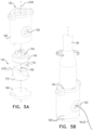
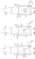
- Figs. 5A-B , 6A-C , 7A-L , and to Figs. 8A-E , 9A-C are schematic illustrations showing adjustment mechanisms 136 and 236, respectively comprising winches 140 and 240, in accordance with some applications. Features common to adjustment mechanisms 136 and 236 will be presented first, followed by description of aspects unique to each winch.
- in winches 140, 240, spool 142, 242 is not coaxial with rotation axis d148, d248. Instead, and as described in more detail hereinbelow, spool 142, 242 is disposed orthogonally to axis d148, d248. It is to be noted that, despite this, winch 140, 240 are also bidirectionally rotational by driver 66.
- Tether 44 (e.g., a proximal end thereof) is fixedly attached (e.g. tied, crimped, soldered, brazed or welded) to spool 142, 242.
- spool 142, 242 is shaped to define an eye 180, 280 that facilitates this affixation.
- tether 44 is drawn into the winch and is wound around the respective spool 142, 242.
- the position and orientation at which spool 142, 242 is coupled to mount 146, 246, respectively inhibits subsequent unwinding of tether 44 from the spool in response to pulling of the end portion away from the spool. In this way, pulling force applied to spool 142, 242 does not result in substantial rotational movement, yielding a stable rotational orientation of winch 140, 240.
- the position and orientation at which spool 142, 242 is coupled, respectively, to mount 146, 246 at least in part precludes the need for adjustment mechanism 136, 236 to comprise a discrete locking mechanism (e.g., a discrete actuatable locking mechanism).
- a discrete locking mechanism e.g., a discrete actuatable locking mechanism
- spool 42 is fixedly coupled to mount 46 in a position and an orientation that provides at least one stable rotational orientation (e.g. exactly one stable rotational orientation) of the mount at which the pulling is inhibited from rotating the mount in the reverse rotational direction about rotation axis d48. That is, depending on an initial rotational orientation of winch 40, application of a pulling force to end portion 62 of tether 44 can rotate the winch almost one complete turn until the winch reaches a stable position.
- stable rotational orientation e.g. exactly one stable rotational orientation
- spool 142, 242 is fixedly coupled to mount 146, 246 in a position and an orientation that provides at least two stable rotational orientations of the mount at which pulling is inhibited from rotating the mount in the reverse rotational direction about rotation axis d148, d248. That is, depending on an initial rotational orientation of the winch, application of a pulling force to the end portion 62 of tether 44 can rotate the winch almost half a turn until the winch reaches a stable position.
- Spool 142, 242 is fixedly coupled to respective mount 146, 246.
- spool 142, 242 is shaped to define a spool axis d150, d250 disposed orthogonally to rotation axis d148, d248 (e.g., passing through the rotation axis).
- winch 140, 240 is housed within housing 168, 268 such that mount 146, 246 and spool 142, 242 rotate about axis d148, d248 with respect to the housing.
- driver interface 164, 264 can be accessible to driver 66, while winch 140, 240 is housed within housing 168, 268. Accessibility of driver interface 164, 264 while winch 140, 240 is housed within housing 168, 268 facilitates the engaging and driving of the winch, by driver 66, while the winch is housed within the housing.
- housing 168 is shaped to define an aperture 190 therethrough, the aperture configured to facilitate passage of tether 44 from outside winch 140 to spool 142 as the spool draws end portion 62 of the tether toward the winch.
- winch 140, 240 comprises at least one inclined guide 170, 270.
- inclined guide 170, 270 is coupled to mount 146, 246.
- mount 146, 246 is shaped to define guide 170, 270.
- guide 170, 270 can be integral to mount 146, 246 (i.e. molded from the same material).
- inclined guide 170, 270 is coupled to mount 146, 246 and disposed laterally from rotation axis d148, 248. In this way, inclined guide 170, 270 is positioned such that, upon rotation of mount 146, 246 in the forward rotational direction, the inclined guide guides tether 44 around spool 142, 242.
- inclined guide 170 is shaped such that, upon driving of driver interface 164 by driver 66, the inclined guide rotates with the mount about rotation axis d148.
- inclined guide 170 defines a guide surface 172 that extends helically around and along rotation axis d148. Contact of tether 44 with guide surface 172 along a helical slope of inclined guide 170 facilitates translation of circular movement of mount 146 into wrapping of tether 44 about spool 142.
- winch 140 includes a first inclined guide 170a and a second inclined guide 170b.
- First inclined guide 170a is positioned such that, upon rotation of mount 146 in the forward rotational direction, the first inclined guide guides tether 44 to a second side 182b of spool 142.
- Second inclined guide 170b is positioned such that, upon forward rotation of mount 146, the second inclined guide guides tether 44 to a first side 182a of spool 142.
- first inclined guide 170a is disposed generally on first side 182a of the spool
- second inclined guide 170b is disposed generally on second side 182b of the spool.
- guiding of tether 44, by respective inclined guides 170a and 170b, to respective sides 174, 176 of spool 142 is facilitated by the winch being shaped to define two shoulders: a first shoulder 178a at which first inclined guide 170a is coupled to a second side 182b of spool 142, and a second shoulder 178b at which second inclined guide 170b is coupled to a first side 182a of spool 142.
- inclined guides 170a, 170b are positioned such that, upon forward rotation of mount 146, the first inclined guide guides tether 44 over first shoulder 178a to second side 182b of the spool, and the second inclined guide guides the tether over second shoulder 178b to the first side 182a of the spool.
- forward rotation of winch 140 initially causes tether 44 to contact inclined guide 170a at guide surface 172a.
- tether 44 continues forward rotation of winch 140 causes tether 44 to be guided along guide surface 172a, towards first shoulder 178a.
- continued forward rotation of winch 140 causes tether 44 to be guided further, over first shoulder 178a, such that the tether becomes draped over second side 182b of spool 142.
- one half turn of forward rotation of winch 140 facilitates wrapping tether 44 about at least one half of a circumference of spool 142.
- a rotational force when a rotational force is no longer applied to winch 140 (e.g., upon disengagement of driver 66 from the winch), if a pulling force (solid arrow in Fig. 7L ) is applied to tether 44, it is not significantly translated into reverse rotation of winch 140, nor into unwinding of the tether. It is hypothesized that the pulling force is not significantly translated into reverse rotation of the winch at least in part since spool 142 is fixedly coupled to mount 146 orthogonally to rotation axis d148. That is, tension on tether 44 "attempts" to rotate spool 142 about spool axis d150 (represented by the broken arrow in Fig.
- an adjustment mechanism 136 comprises a discrete locking mechanism (e.g., a discrete actuatable locking mechanism). It is further hypothesized that this thereby contributes to the simplicity and ease of use of winch 140.
- FIGS. 8A-E , 9A-C are schematic illustrations showing winch 240 comprising mount 246 and spool 242, in accordance with some applications.
- inclined guides 270a, 270b of winch 240 are similar to that of inclined guide 170 of winch 140, guides 270a, 270b of winch 240 are not configured to directly contact tether 44, but instead are configured to indirectly guide the tether by guiding an eyelet 288 that defines an aperture 290 through which the tether passes.
- aperture 290 is configured to facilitate passage of tether 44 from outside winch 240 to spool 242 as the spool draws the end portion 62 of the tether toward the winch.
- eyelet 288 is mechanically engaged with guide surfaces 272a, 272b of guides 270a, 270b such that, upon rotation of mount 246 in the forward rotational direction, the guides guide the eyelet linearly parallel to rotation axis d248.
- winch 240 comprises inclined guides 270a, 270b that each extend helically around and along rotation axis d248, typically parallel with each other.
- inclined guides 270a, 270b are coupled to mount 246.
- mount 246 is shaped to define guides 270a, 270b.
- guides 270a, 270b can be integral to mount 246 (i.e. molded from the same material).
- adjustment mechanism 236 further comprises a housing 268 that houses winch 240.
- housing 268 is configured to facilitate rotation of mount 246 and spool 242 about rotation axis d248, with respect to the housing.
- adjustment mechanism 236 (e.g., housing 268 thereof) defines a track 284 along a track axis d286, which is typically parallel to rotation axis d248.
- Eyelet 288 is mechanically engaged with track 284, such that the eyelet is linearly slidable along the track.
- the mechanical engagement of eyelet 288 with (i) guide surfaces 272a and 272b, and (ii) track 284, translates rotation of winch 240 (including guides 270a and 270b) into reciprocating movement of the eyelet along the track.
- This movement of the eyelet 288 guides tether 44 around one side and then the other side of spool 242. Thereby, (1) longitudinal motion of eyelet 288 and end portion 62 of tether 44 in relation to housing 268, and (2) forward rotation of mount 246, winds the tether around spool 242.
- spool axis d250 is orthogonal to the axis d248 about which mount 246 is configured to rotate.
- winch 240 is unable to rotate about axis d250 within housing 268, similarly obviating both a locking mechanism and a locking-actuating mechanism from winch 240 and contributing to the simplicity and ease of use of the winch.
- FIG. 10 is a schematic illustration of a multi-component system 310 comprising an implant 300, and a delivery tool 312 for delivering the implant 300 to a heart 390 of a subject, in accordance with some applications.
- Implant 300 comprises an adjustment mechanism 336 that comprises a winch.
- Adjustment mechanism 336 can comprise any of the other adjustment mechanisms described herein, but for the purpose of illustration, it is shown in Figs. 10-11F as comprising adjustment mechanism 236.
- Fig. 10 shows a distal portion of system 310 comprising annuloplasty structure 320 (e.g., an annuloplasty band), disposed partially within a catheter 322 of tool 312.
- structure 320 comprises a sleeve 330 that defines an elongate lumen circumscribed by a lateral wall (e.g., the interior of structure 320 is shaped as an elongate lumen).
- sleeve 330 defines an end wall 334 of annuloplasty structure 320.
- Sleeve 330 is often a flexible sleeve comprising a braided fabric mesh, e.g., comprising polyethylene terephthalate (such as Dacron (TM)).
- Sleeve 330 is often configured to be anchored partially or completely around a cardiac valve annulus 388, and subsequently contracted so as to adjust a perimeter of the annulus (i.e., to circumferentially tighten the annulus).
- Annuloplasty structure 320 comprises a flexible elongate tether 344 that extends, along at least a portion of sleeve 330, e.g., to an end portion 362 of the tether. The portion of the sleeve along which the tether extends is thereby a contracting portion of the sleeve.
- tether 344 generally corresponds to tether 44 described hereinabove, mutatis mutandis.
- sleeve 330 i.e. an outer, lateral surface thereof
- a connector 370 e.g., by stitches
- Tether 344 can comprise a wire, a ribbon, a rope, or a band, and can comprise a flexible and/or superelastic material, e.g., nitinol, polyester, stainless steel, or cobalt chrome.
- the wire comprises a radiopaque material.
- tether 344 comprises a braided polyester suture (e.g., Ticron).
- tether 344 is coated with polytetrafluoroethylene (PTFE).
- tether 344 comprises a plurality of wires that are intertwined to form a rope structure.
- Adjustment mechanism 336 facilitates axial contracting (and re-expanding) of annuloplasty structure 320.
- adjustment mechanism 336 comprises a winch that comprises a spool, arranged such that rotation of the winch winds tether 344 around the spool, drawing the tether into the winch. This thereby contracts implant structure 320.
- adjustment mechanism 336 comprises a housing within which the winch is disposed, as described hereinabove. Adjustment mechanism 336 (e.g., the spool thereof) is coupled to tether 344.
- the winch of the adjustment mechanism When the winch of the adjustment mechanism is rotated (e.g., with respect to its housing), the winch adjusts a length of structure 320 by applying tension to tether 344 (or by releasing the tension). Particularly, drawing of end portion 362 of tether 344 toward adjustment mechanism 336 reduces a length of structure 320.
- System 310 often comprises a flexible, longitudinal guide member 346 (e.g., a wire) coupled to a portion of the winch.
- guide member 346 e.g., a wire
- structure 320 is disposed at a distal portion of the catheter, and guide member 346 is coupled to the winch of adjustment mechanism 336.
- guide member 346 extends from adjustment mechanism 336 (e.g., the driver interface thereof) and proximally through catheter 322 (e.g., through a parallel side-lumen of the catheter).
- a proximal portion of guide member 346 is accessible from outside the body of the subject.
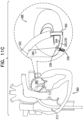
- Figs. 11A-F are schematic illustrations showing use of adjustment mechanism 336 in system 310 comprising implant 300 and delivery tool 312, in accordance with some applications.
- delivery tool 312 comprises a catheter 322, the distal portion of the catheter being advanceable (e.g., transluminally steerable) into the body of the subject.
- structure 320 is advanced into left atrium 380 using catheter 322.
- catheter 322 can be advanced first, and structure 320 (or another implant) can be subsequently advanced through the catheter.
- a transfemoral transseptal approach to the mitral valve is shown in Fig. 11A
- the scope herein includes alternate approaches to the mitral valve, to the tricuspid valve, to other locations in (e.g., valves of) the heart, and to other locations in the body.
- annuloplasty structure 320 can be advanced with an anchor deployment manipulator 360 disposed in an anchor channel 350, within the interior of the annuloplasty structure.
- anchor deployment manipulator 360 can be introduced into the interior after advancement of annuloplasty structure 320 (or another implant).
- the winch is moved away from end wall 334 ( Fig. 11B ). For some applications, this is achieved by guide member 346 being moved proximally such that adjustment mechanism 336 (and the winch thereof) moves (e.g., translates, deflects, and/or rotates) away from the longitudinal axis of the sleeve, often to become disposed laterally from sleeve 330.
- connectors 370 facilitate this technique by flexibly and/or articulatably coupling adjustment mechanism 336 to sleeve 330.
- guide member 346 is also tensioned or relaxed in order to reposition the adjustment mechanism.
- adjustment mechanism 336 (and the winch thereof) away from end wall 334 of sleeve 330 advantageously facilitates (1) advancement of the structure to the mitral valve while adjustment mechanism 336 is disposed on the longitudinal axis of sleeve 330 (e.g., collinearly with the sleeve), so as to maintain a small cross-sectional diameter of the structure for transluminal delivery; and (2) subsequently movement of the adjustment mechanism away from the longitudinal axis, e.g., so as to allow end wall 334 of the sleeve to be placed against the annulus, and/or so as to allow anchor 338 to be driven through the end wall of the sleeve ( Fig. 11B ).
- implant 300 comprises at least one anchor 338 configured to anchor tether 344 (e.g., end portion 362 thereof) to a tissue of the subject.
- anchors 338 are deployed from a distal end of manipulator 360 into tissue of a subject.
- anchor deployment manipulator 360 is advanced into a lumen of sleeve 330 (typically within anchor channel 350), and, from within the lumen, deploys the anchors through a wall of the sleeve and into cardiac tissue. This process is repeated for several anchors 338 along sleeve 330, in order to anchor the sleeve around a portion of the valve annulus.
- annuloplasty structure 320 is implanted using techniques described, mutatis mutandis, in one or more of the following publications:
- anchor 338 is implanted using manipulator 360 contained within sleeve 330 of annuloplasty structure 320 while at least a portion of annuloplasty structure 320 (e.g., a proximal portion) is contained within surrounding catheter 322.
- a successive portion of sleeve 330 is freed, and deployment manipulator 360 is repositioned along annulus 388 to a second site selected for deployment of a second one of anchors 338.
- Fig. 11D shows a second tissue anchor 338 (shown as a second tissue anchor 338b) being deployed through a portion of the lateral wall of sleeve 330.
- the first one of anchors 338 deployed through end wall 334 is labeled as anchor 338a.
- Deployment manipulator 360 deploys the second tissue anchor by driving the anchor to penetrate and pass through the wall of sleeve 330 into cardiac tissue at the second site.
- anchor 338b is implanted while at least a portion of annuloplasty structure 320 (e.g., a proximal portion) is contained within surrounding catheter 322.
- a portion of the lateral wall of sleeve 330 is aligned against the tissue of in a manner in which a surface of the portion of the lateral wall is disposed in parallel with the planar surface of the tissue.
- Fig. 11E shows the entire length of sleeve 330 having been anchored, via a plurality of anchors 338, to annulus 388, as described hereinabove.
- the deployment manipulator i.e., deployment manipulator 360 described herein but not shown in Fig. 11E
- the deployment manipulator can be repositioned along the annulus to additional sites, at which respective anchors are deployed, until the last anchor is deployed. Then, delivery tool 312 is removed, leaving behind annuloplasty structure 320, typically with guide member 346 coupled thereto.
- driver 66 is slidable over and along guide member 346.
- Fig. 11F shows driver 66 having been advanced over and along guide member 346.
- driver 66 typically comprises a rotation tool, and is configured to engage and drive (e.g., rotate) the winch of adjustment mechanism 336, so as to tension tether 344, and thereby axially contract sleeve 330, in response to a rotational force applied to the winch.
- driver 66 can be disengaged from the winch of adjustment mechanism 336, typically without actuating or otherwise activating a locking mechanism.
- adjustment mechanism 336 typically does not comprise a discrete locking mechanism (e.g., a discrete actuatable locking mechanism).
- implant 300 comprises a different type of annuloplasty structure to that shown hereinabove.
- adjustment mechanism 336 can be used, mutatis mutandis, as a component of an annuloplasty structure described in one or more of the following publications:
- implant 300 is described as comprising an annuloplasty structure 320 that is anchored to tissue of an annulus of a native heart valve.
- the systems, apparatuses, and techniques described herein can be used to facilitate adjustment of other implants, mutatis mutandis.
- the adjustment mechanisms described herein can be used as a component of an artificial chorda tendinea structure, e.g., in order to adjust a length and/or tension of the artificial chorda tendinea structure.
- the adjustment mechanisms described herein can be used instead of an adjustment mechanism of an artificial chorda tendinea structure described in one or more of the following publications:
Landscapes
- Health & Medical Sciences (AREA)
- Life Sciences & Earth Sciences (AREA)
- Surgery (AREA)
- Heart & Thoracic Surgery (AREA)
- Engineering & Computer Science (AREA)
- Biomedical Technology (AREA)
- Nuclear Medicine, Radiotherapy & Molecular Imaging (AREA)
- Medical Informatics (AREA)
- Molecular Biology (AREA)
- Animal Behavior & Ethology (AREA)
- General Health & Medical Sciences (AREA)
- Public Health (AREA)
- Veterinary Medicine (AREA)
- Rheumatology (AREA)
- Prostheses (AREA)
Claims (15)
- Système comprenant un implant médical (300), l'implant (300) comprenant :un filin (44), présentant une partie terminale (62) ; etun treuil (40), comprenant :une interface d'organe d'entraînement (64), pouvant entrer en prise et être entraînée par un organe d'entraînement (66) pouvant être avancé par voie transcathéter,un support (46), accouplé à l'interface d'organe d'entraînement (64) de telle sorte que l'entraînement de l'interface d'organe d'entraînement (64) par l'organe d'entraînement (66) fasse tourner le support (46) autour d'un axe de rotation (d48), etune bobine (42) :définissant un axe longitudinal (d50) de la bobine,accouplée au filin (44), le filin (44) s'étendant loin du treuil (40) vers la partie terminale (62), etaccouplée à demeure au support (46) de telle sorte que :la rotation du support (46) autour de l'axe de rotation (d48) entraîne la partie terminale (62) du filin (44) vers la bobine (42) en enroulant le filin (44) autour de l'axe longitudinal de bobine (d50) de la bobine (42), etl'axe longitudinal de bobine (d50) n'est pas coaxial avec l'axe de rotation (d48).
- Système selon la revendication 1, dans lequel la bobine (42) est accouplée à demeure au support (46) telle sorte que la bobine (42) soit entièrement disposée latéralement par rapport à l'axe de rotation (d48).
- Système selon la revendication 1 ou la revendication 2, dans lequel l'axe longitudinal de bobine (d50) est parallèle à l'axe de rotation (d48).
- Système selon l'une quelconque des revendications 1 à 3, comprenant en outre un logement (68) qui abrite le treuil (40), le logement (68) étant configuré pour faciliter le mouvement du support (46) et de la bobine (42) autour de l'axe de rotation (d48), par rapport au logement (68).
- Système selon la revendication 4, dans lequel l'interface d'organe d'entraînement (64) est accessible à l'organe d'entraînement (66) pendant que le treuil (40) est logé dans le logement (68).
- Système selon la revendication 5, dans lequel le logement (68) est formé pour définir une ouverture (90), le filin (44) s'étend à partir de la bobine (42), hors du treuil (40) par le biais de l'ouverture (90), et s'éloigne du treuil (40) vers la partie terminale (62), et l'ouverture (90) est configurée pour faciliter le passage du filin (44) dans le treuil (40) à mesure que la bobine (42) tire la partie terminale (62) du filin (44) vers le treuil (40).
- Système selon l'une quelconque des revendications 1 à 6, dans lequel l'implant (300) comprend en outre au moins un ancrage (338) configuré pour ancrer la partie terminale (62) du filin (44) au tissu d'un sujet,
dans lequel l'implant (300) comprend éventuellement une structure d'annuloplastie (320), et est configuré de telle sorte que le fait de tirer la partie terminale (62) du filin (44) vers le treuil (40) réduit une longueur de la structure (320). - Système selon l'une quelconque des revendications 1 à 7, dans lequel la bobine (42) est accouplée à demeure au support (46) latéralement par rapport à l'axe de rotation (d48), de telle sorte que, dans une section transversale du treuil (40) orthogonale à l'axe de rotation (d48), un rayon du treuil (40) :s'étende radialement vers l'extérieur à partir de l'axe de rotation (d48) vers la bobine (42),atteigne la bobine (42) au niveau d'un premier point de surface (54) de la bobine (42),traverse la bobine (42), etsorte de la bobine (42) au niveau d'un second point de surface (56) de la bobine (42) ;dans lequel, éventuellement, dans la section transversale :a) la bobine (42) a une forme de section transversale qui est trapézoïdale et/ou en forme de D ; oub) le premier point de surface (54) de la bobine (42) est un point de la bobine (42) le plus proche de l'axe de rotation (d48), dans lequel, dans la section transversale, le premier point de surface (54) de la bobine (42) est éventuellement à au moins 0,2 mm de l'axe de rotation (d48).
- Système selon l'une quelconque des revendications 1 à 8, dans lequel la bobine (42) est accouplée à demeure au support (46) orthogonalement à l'axe de rotation (d48).
- Système selon la revendication 9, dans lequel le treuil (40) comprend au moins un guide incliné (170) accouplé au support (46), disposé latéralement par rapport à l'axe de rotation (d48), et positionné de telle sorte que, lors de la rotation du support (46) dans le sens de rotation avant, l'au moins un guide incliné (170) guide le filin (44) autour de la bobine (42).
- Système selon la revendication 10, dans lequel :a) l'au moins un guide incliné (170) est accouplé à demeure au support (46) de telle sorte que, lors de l'entraînement de l'interface d'organe d'entraînement (64) par l'organe d'entraînement (66), l'au moins un guide incliné (170) se déplace avec le support (46) autour de l'axe de rotation ; oub) l'au moins un guide incliné (170) définit une surface de guidage (172) qui s'étend de manière hélicoïdale autour et le long de l'axe de rotation (d48) ; ouc) l'au moins un guide incliné (170) comprend un premier guide incliné (170a) et un second guide incliné (170b),le premier guide incliné (170a) est positionné de telle sorte que, lors de la rotation du support (46) dans le sens de rotation avant, le premier guide incliné (170a) guide le filin (44) vers un second côté de la bobine (42), etle second guide incliné (170b) est positionné de telle sorte que, lors de la rotation du support (46) dans le sens de rotation avant, le second guide incliné (170b) guide le filin (44) vers un premier côté de la bobine (42) qui est opposé au second côté de la bobine (42).
- Système selon la revendication 11, dans lequel :le treuil (40) définit un premier épaulement (178a) au niveau duquel le premier guide incliné (170a) est accouplé à une première extrémité de la bobine (42), et un second épaulement (178b) au niveau duquel le second guide incliné (170b) est accouplé à une seconde extrémité de la bobine (42),le premier guide incliné (170a) est positionné de telle sorte que, lors de la rotation du support (46) dans le sens de rotation avant, le premier guide incliné (170a) guide le filin (44) par-dessus le premier épaulement (178a) vers le second côté de la bobine (42), etle second guide incliné (170b) est positionné de telle sorte que, lors de la rotation du support (46) dans le sens de rotation avant, le second guide incliné (170b) guide le filin (44) par-dessus le second épaulement (178b) vers le premier côté de la bobine (42).
- Système selon la revendication 10, comprenant en outre un œillet (288) qui définit une ouverture (290) à travers celui-ci, l'ouverture (290) étant configurée pour faciliter le passage du filin (44) de l'extérieur du treuil (40) à la bobine (42) à mesure que la bobine (42) tire la partie terminale (62) du filin (44) vers le treuil (40), l'œillet (288) est en prise mécanique avec le guide (170) de telle sorte que, lors de la rotation du support (46) dans le sens de rotation avant, l'au moins un guide incliné (170) guide le filin (44) autour de la bobine (42) en déplaçant l'œillet (288) longitudinalement, parallèlement à l'axe de rotation (d48).
- Système selon la revendication 4 et les revendications 5 à 13 dans la mesure où elles dépendent de la revendication 4, dans lequel le logement (68) définit une piste longitudinale (284) le long d'un axe de piste (d286), parallèle à l'axe de rotation (d48), la piste (284) étant configurée pour faciliter, lors de la rotation du support (46) dans le sens de rotation avant, le déplacement longitudinal de l'œillet (288) le long de l'axe de piste (d286).
- Procédé, comprenant :
la pose par voie transcathéter d'un implant médical dans un tissu, l'implant comportant :un filin, présentant une partie terminale ; etun treuil, comportant :une interface d'organe d'entraînement,un support, accouplé à l'interface d'organe d'entraînement de telle sorte que l'entraînement de l'interface d'organe d'entraînement fasse tourner le support autour d'un axe de rotation, etune bobine :définissant un axe longitudinal de bobine qui n'est pas coaxial avec l'axe de rotation,accouplée au filin, le filin s'étendant loin du treuil vers la partie terminale, etaccouplée à demeure au support ; ettirant la partie terminale du filin vers la bobine en enroulant le filin autour de l'axe longitudinal de la bobine qui n'est pas coaxial avec l'axe de rotation en faisant tourner le support autour de l'axe de rotation, dans lequel le procédé est réalisé sur une simulation non vivante,éventuellement comprenant en outre l'entrée en prise de l'interface d'organe d'entraînement avec un organe d'entraînement, dans lequel la rotation du support autour de l'axe de rotation comprend la rotation du support autour de l'axe de rotation en entraînant l'interface d'organe d'entraînement avec l'organe d'entraînement et, après avoir posé l'implant dans le tissu par voie transcathéter, et avant de mettre en prise l'interface d'organe d'entraînement avec l'organe d'entraînement, l'avancée par voie transcathéter de l'organe d'entraînement vers l'interface d'organe d'entraînement.
Applications Claiming Priority (2)
| Application Number | Priority Date | Filing Date | Title |
|---|---|---|---|
| US202062993669P | 2020-03-23 | 2020-03-23 | |
| PCT/IB2021/051902 WO2021191713A1 (fr) | 2020-03-23 | 2021-03-08 | Treuil autobloquant |
Publications (2)
| Publication Number | Publication Date |
|---|---|
| EP4096529A1 EP4096529A1 (fr) | 2022-12-07 |
| EP4096529B1 true EP4096529B1 (fr) | 2025-05-07 |
Family
ID=75223334
Family Applications (1)
| Application Number | Title | Priority Date | Filing Date |
|---|---|---|---|
| EP21714385.8A Active EP4096529B1 (fr) | 2020-03-23 | 2021-03-08 | Treuil autobloquant |
Country Status (4)
| Country | Link |
|---|---|
| US (1) | US12588907B2 (fr) |
| EP (1) | EP4096529B1 (fr) |
| CN (1) | CN115666411B (fr) |
| WO (1) | WO2021191713A1 (fr) |
Families Citing this family (38)
| Publication number | Priority date | Publication date | Assignee | Title |
|---|---|---|---|---|
| EP3848002A1 (fr) | 2008-12-22 | 2021-07-14 | Valtech Cardio, Ltd. | Dispositifs d'annuloplastie réglables et mécanismes de réglage associés |
| US10517719B2 (en) | 2008-12-22 | 2019-12-31 | Valtech Cardio, Ltd. | Implantation of repair devices in the heart |
| US8715342B2 (en) | 2009-05-07 | 2014-05-06 | Valtech Cardio, Ltd. | Annuloplasty ring with intra-ring anchoring |
| US8545553B2 (en) | 2009-05-04 | 2013-10-01 | Valtech Cardio, Ltd. | Over-wire rotation tool |
| WO2013069019A2 (fr) | 2011-11-08 | 2013-05-16 | Valtech Cardio, Ltd. | Fonction d'orientation commandée d'un outil de pose d'implant |
| US9968452B2 (en) | 2009-05-04 | 2018-05-15 | Valtech Cardio, Ltd. | Annuloplasty ring delivery cathethers |
| US12485010B2 (en) | 2009-05-07 | 2025-12-02 | Edwards Lifesciences Innovation (Israel) Ltd. | Multiple anchor delivery tool |
| US10098737B2 (en) | 2009-10-29 | 2018-10-16 | Valtech Cardio, Ltd. | Tissue anchor for annuloplasty device |
| EP2723274B1 (fr) | 2011-06-23 | 2017-12-27 | Valtech Cardio, Ltd. | Élément de fermeture utilisable avec une structure d'annuloplastie |
| US10792152B2 (en) | 2011-06-23 | 2020-10-06 | Valtech Cardio, Ltd. | Closed band for percutaneous annuloplasty |
| US8858623B2 (en) | 2011-11-04 | 2014-10-14 | Valtech Cardio, Ltd. | Implant having multiple rotational assemblies |
| EP2886084B1 (fr) | 2011-12-12 | 2018-02-14 | David Alon | Dispositif de réparation de valvule cardiaque |
| EP3730066A1 (fr) | 2012-10-23 | 2020-10-28 | Valtech Cardio, Ltd. | Techniques d'ancrage de tissu percutané |
| EP3730084A1 (fr) | 2012-10-23 | 2020-10-28 | Valtech Cardio, Ltd. | Fonction de direction contrôlée pour outil de pose d'implant |
| EP2961351B1 (fr) | 2013-02-26 | 2018-11-28 | Mitralign, Inc. | Dispositif pour réparation percutanée de valve tricuspide |
| US10449333B2 (en) | 2013-03-14 | 2019-10-22 | Valtech Cardio, Ltd. | Guidewire feeder |
| CN105283214B (zh) | 2013-03-15 | 2018-10-16 | 北京泰德制药股份有限公司 | 平移导管、系统及其使用方法 |
| US10070857B2 (en) | 2013-08-31 | 2018-09-11 | Mitralign, Inc. | Devices and methods for locating and implanting tissue anchors at mitral valve commissure |
| WO2015059699A2 (fr) | 2013-10-23 | 2015-04-30 | Valtech Cardio, Ltd. | Chargeur d'éléments d'ancrage |
| EP3288496B1 (fr) | 2015-04-30 | 2024-05-29 | Edwards Lifesciences Innovation (Israel) Ltd. | Technologies d'annuloplastie |
| EP3397207B1 (fr) | 2015-12-30 | 2026-04-01 | Edwards Lifesciences Corporation | Système de réduction de régurgitation tricuspide |
| GB201611910D0 (en) | 2016-07-08 | 2016-08-24 | Valtech Cardio Ltd | Adjustable annuloplasty device with alternating peaks and troughs |
| US11045627B2 (en) | 2017-04-18 | 2021-06-29 | Edwards Lifesciences Corporation | Catheter system with linear actuation control mechanism |
| US10835221B2 (en) | 2017-11-02 | 2020-11-17 | Valtech Cardio, Ltd. | Implant-cinching devices and systems |
| US11135062B2 (en) | 2017-11-20 | 2021-10-05 | Valtech Cardio Ltd. | Cinching of dilated heart muscle |
| CN116531147A (zh) | 2018-01-24 | 2023-08-04 | 爱德华兹生命科学创新(以色列)有限公司 | 瓣环成形术结构的收缩 |
| EP3743014B1 (fr) | 2018-01-26 | 2023-07-19 | Edwards Lifesciences Innovation (Israel) Ltd. | Techniques pour faciliter la fixation de valve cardiaque et le remplacement de cordon |
| WO2020012481A2 (fr) | 2018-07-12 | 2020-01-16 | Valtech Cardio, Ltd. | Systèmes d'annuloplastie et outils de verrouillage associés |
| CR20210575A (es) | 2019-05-29 | 2022-02-28 | Valtech Cardio Ltd | Sistemas y métodos de manejo de ancla de tejido |
| EP3998958A1 (fr) | 2019-07-16 | 2022-05-25 | Heartchord Medical, Inc. | Systèmes et méthodes de remodelage d'un tissu |
| CA3141295A1 (fr) | 2019-07-23 | 2021-01-28 | Valtech Cardio, Ltd. | Contraction d'une structure d'annuloplastie |
| EP4021551A1 (fr) | 2019-08-28 | 2022-07-06 | Valtech Cardio, Ltd. | Cathéter orientable à faible encombrement |
| JP2022546160A (ja) | 2019-08-30 | 2022-11-04 | エドワーズ ライフサイエンシーズ イノベーション (イスラエル) リミテッド | アンカーチャネル先端 |
| JP2022551425A (ja) | 2019-09-25 | 2022-12-09 | カーディアック・インプランツ・エルエルシー | 心臓弁輪縮小システム |
| CN121337517A (zh) | 2019-10-29 | 2026-01-16 | 爱德华兹生命科学创新(以色列)有限公司 | 瓣环成形术和组织锚固技术 |
| EP4096529B1 (fr) * | 2020-03-23 | 2025-05-07 | Edwards Lifesciences Innovation (Israel) Ltd. | Treuil autobloquant |
| WO2021236634A2 (fr) | 2020-05-20 | 2021-11-25 | Cardiac Implants, Llc | Réduction du diamètre d'un anneau valvulaire cardiaque avec commande indépendante sur chacun des ancrages qui sont lancés dans l'anneau |
| CN116531148B (zh) * | 2023-07-05 | 2023-10-20 | 科瑞迈吉(北京)医疗科技有限公司 | 一种用于瓣膜修复手术的锁线系统 |
Family Cites Families (785)
| Publication number | Priority date | Publication date | Assignee | Title |
|---|---|---|---|---|
| NL143127B (nl) | 1969-02-04 | 1974-09-16 | Rhone Poulenc Sa | Versterkingsorgaan voor een defecte hartklep. |
| US3604488A (en) | 1969-11-19 | 1971-09-14 | Vermont American Corp | Screwdriver attachment |
| US3840018A (en) | 1973-01-31 | 1974-10-08 | M Heifetz | Clamp for occluding tubular conduits in the human body |
| US3881366A (en) | 1973-11-19 | 1975-05-06 | Gen Motors Corp | Adjustable steering column |
| US3898701A (en) | 1974-01-17 | 1975-08-12 | Russa Joseph | Implantable heart valve |
| US4042979A (en) | 1976-07-12 | 1977-08-23 | Angell William W | Valvuloplasty ring and prosthetic method |
| US4118805A (en) | 1977-02-28 | 1978-10-10 | Codman & Shurtleff, Inc. | Artificial sphincter |
| ES474582A1 (es) | 1978-10-26 | 1979-11-01 | Aranguren Duo Iker | Procedimiento para la instalacion de valvulas mitrales en sulugar anatomico, mediante anclaje de cordajes en pilar arti-ficial |
| US4214349A (en) | 1978-11-30 | 1980-07-29 | Midland-Ross Corporation | Tie wrap |
| ES244903Y (es) | 1979-07-31 | 1980-12-01 | Protesis anular regulable para cirugia cardiaca | |
| GB2084468B (en) | 1980-09-25 | 1984-06-06 | South African Inventions | Surgical implant |
| US4473928A (en) | 1980-11-20 | 1984-10-02 | Tridon Limited | Hose clamps |
| DE3230858C2 (de) | 1982-08-19 | 1985-01-24 | Ahmadi, Ali, Dr. med., 7809 Denzlingen | Ringprothese |
| US4434828A (en) | 1982-12-20 | 1984-03-06 | Richard Trincia | Screwdriver with handle for storing bits |
| US4625727A (en) | 1985-01-24 | 1986-12-02 | Leiboff Arnold R | Anastomosis device with excisable frame |
| US4712549A (en) | 1985-07-01 | 1987-12-15 | Edward Weck & Co. | Automatic hemostatic clip applier |
| CA1303298C (fr) | 1986-08-06 | 1992-06-16 | Alain Carpentier | Prothese souple pour soutenir les valvules cardiaques |
| US4961738A (en) | 1987-01-28 | 1990-10-09 | Mackin Robert A | Angioplasty catheter with illumination and visualization within angioplasty balloon |
| US4917698A (en) | 1988-12-22 | 1990-04-17 | Baxter International Inc. | Multi-segmented annuloplasty ring prosthesis |
| EP0595791B1 (fr) | 1989-02-13 | 1999-06-30 | Baxter International Inc. | Prothèse annulaire pour anuloplastie |
| US5290300A (en) | 1989-07-31 | 1994-03-01 | Baxter International Inc. | Flexible suture guide and holder |
| US5632746A (en) | 1989-08-16 | 1997-05-27 | Medtronic, Inc. | Device or apparatus for manipulating matter |
| US4935027A (en) | 1989-08-21 | 1990-06-19 | Inbae Yoon | Surgical suture instrument with remotely controllable suture material advancement |
| SE467459B (sv) | 1990-09-25 | 1992-07-20 | Allset Marine Lashing Ab | Vridlaas foer hoernlaadorna till containrar |
| US5626609A (en) | 1990-10-05 | 1997-05-06 | United States Surgical Corporation | Endoscopic surgical instrument |
| US5042707A (en) | 1990-10-16 | 1991-08-27 | Taheri Syde A | Intravascular stapler, and method of operating same |
| US5064431A (en) | 1991-01-16 | 1991-11-12 | St. Jude Medical Incorporated | Annuloplasty ring |
| US5108420A (en) | 1991-02-01 | 1992-04-28 | Temple University | Aperture occlusion device |
| US5329923A (en) | 1991-02-15 | 1994-07-19 | Lundquist Ingemar H | Torquable catheter |
| US5346498A (en) | 1991-11-06 | 1994-09-13 | Imagyn Medical, Inc. | Controller for manipulation of instruments within a catheter |
| US5201880A (en) | 1992-01-27 | 1993-04-13 | Pioneering Technologies, Inc. | Mitral and tricuspid annuloplasty rings |
| US5325845A (en) | 1992-06-08 | 1994-07-05 | Adair Edwin Lloyd | Steerable sheath for use with selected removable optical catheter |
| US5300034A (en) | 1992-07-29 | 1994-04-05 | Minnesota Mining And Manufacturing Company | Iv injection site for the reception of a blunt cannula |
| US5258008A (en) | 1992-07-29 | 1993-11-02 | Wilk Peter J | Surgical stapling device and associated method |
| ES2049653B1 (es) | 1992-10-05 | 1994-12-16 | Velazquez Francisco Farrer | Dispositivo corrector de la incontinencia urinaria femenina. |
| US6074417A (en) | 1992-11-16 | 2000-06-13 | St. Jude Medical, Inc. | Total mitral heterologous bioprosthesis to be used in mitral or tricuspid heart replacement |
| US5643317A (en) | 1992-11-25 | 1997-07-01 | William Cook Europe S.A. | Closure prosthesis for transcatheter placement |
| US5383852A (en) | 1992-12-04 | 1995-01-24 | C. R. Bard, Inc. | Catheter with independent proximal and distal control |
| US5449368A (en) | 1993-02-18 | 1995-09-12 | Kuzmak; Lubomyr I. | Laparoscopic adjustable gastric banding device and method for implantation and removal thereof |
| US5797960A (en) | 1993-02-22 | 1998-08-25 | Stevens; John H. | Method and apparatus for thoracoscopic intracardiac procedures |
| US5972030A (en) | 1993-02-22 | 1999-10-26 | Heartport, Inc. | Less-invasive devices and methods for treatment of cardiac valves |
| US6125852A (en) | 1993-02-22 | 2000-10-03 | Heartport, Inc. | Minimally-invasive devices and methods for treatment of congestive heart failure |
| US6010531A (en) | 1993-02-22 | 2000-01-04 | Heartport, Inc. | Less-invasive devices and methods for cardiac valve surgery |
| US5450860A (en) | 1993-08-31 | 1995-09-19 | W. L. Gore & Associates, Inc. | Device for tissue repair and method for employing same |
| US5464404A (en) | 1993-09-20 | 1995-11-07 | Abela Laser Systems, Inc. | Cardiac ablation catheters and method |
| AU1011595A (en) | 1994-01-13 | 1995-07-20 | Ethicon Inc. | Spiral surgical tack |
| US5843120A (en) | 1994-03-17 | 1998-12-01 | Medinol Ltd. | Flexible-expandable stent |
| US6217610B1 (en) | 1994-07-29 | 2001-04-17 | Edwards Lifesciences Corporation | Expandable annuloplasty ring |
| US5582616A (en) | 1994-08-05 | 1996-12-10 | Origin Medsystems, Inc. | Surgical helical fastener with applicator |
| US5593424A (en) | 1994-08-10 | 1997-01-14 | Segmed, Inc. | Apparatus and method for reducing and stabilizing the circumference of a vascular structure |
| US20020198586A1 (en) | 1995-04-12 | 2002-12-26 | Kanji Inoue | Appliance collapsible for insertion into a human organ and capable of resilient restoration |
| WO1996040006A1 (fr) | 1995-06-07 | 1996-12-19 | St. Jude Medical, Inc. | Dispositif de calibrage reglable destine aux anneaux du coeur |
| US5676653A (en) | 1995-06-27 | 1997-10-14 | Arrow International Investment Corp. | Kink-resistant steerable catheter assembly |
| US5662683A (en) | 1995-08-22 | 1997-09-02 | Ortho Helix Limited | Open helical organic tissue anchor and method of facilitating healing |
| US5749371A (en) | 1995-10-06 | 1998-05-12 | Zadini; Filiberto P. | Automatic guidewire placement device for medical catheters |
| WO1997019655A1 (fr) | 1995-12-01 | 1997-06-05 | Medtronic, Inc. | Prothese pour annuloplastie |
| US5730150A (en) | 1996-01-16 | 1998-03-24 | B. Braun Medical Inc. | Guidewire dispenser |
| US5957953A (en) | 1996-02-16 | 1999-09-28 | Smith & Nephew, Inc. | Expandable suture anchor |
| US5702397A (en) | 1996-02-20 | 1997-12-30 | Medicinelodge, Inc. | Ligament bone anchor and method for its use |
| US5716370A (en) | 1996-02-23 | 1998-02-10 | Williamson, Iv; Warren | Means for replacing a heart valve in a minimally invasive manner |
| US6402780B2 (en) | 1996-02-23 | 2002-06-11 | Cardiovascular Technologies, L.L.C. | Means and method of replacing a heart valve in a minimally invasive manner |
| US6132390A (en) | 1996-02-28 | 2000-10-17 | Eupalamus Llc | Handle for manipulation of a stylet used for deflecting a tip of a lead or catheter |
| US5782844A (en) | 1996-03-05 | 1998-07-21 | Inbae Yoon | Suture spring device applicator |
| US6702846B2 (en) | 1996-04-09 | 2004-03-09 | Endocare, Inc. | Urological stent therapy system and method |
| US5885228A (en) | 1996-05-08 | 1999-03-23 | Heartport, Inc. | Valve sizer and method of use |
| US6569188B2 (en) | 1996-08-05 | 2003-05-27 | Arthrex, Inc. | Hex drive bioabsorbable tissue anchor |
| US5669919A (en) | 1996-08-16 | 1997-09-23 | Medtronic, Inc. | Annuloplasty system |
| US5752963A (en) | 1996-08-19 | 1998-05-19 | Bristol-Myers Squibb Company | Suture anchor driver |
| US5830221A (en) | 1996-09-20 | 1998-11-03 | United States Surgical Corporation | Coil fastener applier |
| CA2217406C (fr) | 1996-10-04 | 2006-05-30 | United States Surgical Corporation | Systeme d'installation d'ancrage de suture avec unite de charge jetable |
| US5716397A (en) | 1996-12-06 | 1998-02-10 | Medtronic, Inc. | Annuloplasty device with removable stiffening element |
| US5935098A (en) | 1996-12-23 | 1999-08-10 | Conceptus, Inc. | Apparatus and method for accessing and manipulating the uterus |
| EP0850607A1 (fr) | 1996-12-31 | 1998-07-01 | Cordis Corporation | Prothèse de valve pour implantation dans des canaux corporels |
| US6183411B1 (en) | 1998-09-21 | 2001-02-06 | Myocor, Inc. | External stress reduction device and method |
| US5961440A (en) | 1997-01-02 | 1999-10-05 | Myocor, Inc. | Heart wall tension reduction apparatus and method |
| US6045497A (en) | 1997-01-02 | 2000-04-04 | Myocor, Inc. | Heart wall tension reduction apparatus and method |
| US6406420B1 (en) | 1997-01-02 | 2002-06-18 | Myocor, Inc. | Methods and devices for improving cardiac function in hearts |
| US6050936A (en) | 1997-01-02 | 2000-04-18 | Myocor, Inc. | Heart wall tension reduction apparatus |
| US6074401A (en) | 1997-01-09 | 2000-06-13 | Coalescent Surgical, Inc. | Pinned retainer surgical fasteners, instruments and methods for minimally invasive vascular and endoscopic surgery |
| US5961539A (en) | 1997-01-17 | 1999-10-05 | Segmed, Inc. | Method and apparatus for sizing, stabilizing and/or reducing the circumference of an anatomical structure |
| US5938616A (en) | 1997-01-31 | 1999-08-17 | Acuson Corporation | Steering mechanism and steering line for a catheter-mounted ultrasonic transducer |
| US5702398A (en) | 1997-02-21 | 1997-12-30 | Tarabishy; Sam | Tension screw |
| US6086582A (en) | 1997-03-13 | 2000-07-11 | Altman; Peter A. | Cardiac drug delivery system |
| US5876373A (en) | 1997-04-04 | 1999-03-02 | Eclipse Surgical Technologies, Inc. | Steerable catheter |
| CA2286656A1 (fr) | 1997-04-11 | 1998-10-22 | Leslie Organ | Catheter orientable avec pointe a electrode rotative et procede d'utilisation |
| EP1009332A2 (fr) | 1997-09-04 | 2000-06-21 | Endocore, Inc. | Remplacement de cordages artificiels |
| FR2768324B1 (fr) | 1997-09-12 | 1999-12-10 | Jacques Seguin | Instrument chirurgical permettant, par voie percutanee, de fixer l'une a l'autre deux zones de tissu mou, normalement mutuellement distantes |
| US5984959A (en) | 1997-09-19 | 1999-11-16 | United States Surgical | Heart valve replacement tools and procedures |
| US6206888B1 (en) | 1997-10-01 | 2001-03-27 | Scimed Life Systems, Inc. | Stent delivery system using shape memory retraction |
| US6174332B1 (en) | 1997-12-05 | 2001-01-16 | St. Jude Medical, Inc. | Annuloplasty ring with cut zone |
| US6332893B1 (en) | 1997-12-17 | 2001-12-25 | Myocor, Inc. | Valve to myocardium tension members device and method |
| US6530952B2 (en) | 1997-12-29 | 2003-03-11 | The Cleveland Clinic Foundation | Bioprosthetic cardiovascular valve system |
| US6251092B1 (en) | 1997-12-30 | 2001-06-26 | Medtronic, Inc. | Deflectable guiding catheter |
| US6533807B2 (en) | 1998-02-05 | 2003-03-18 | Medtronic, Inc. | Radially-expandable stent and delivery system |
| US20020087048A1 (en) | 1998-02-24 | 2002-07-04 | Brock David L. | Flexible instrument |
| US6074418A (en) | 1998-04-20 | 2000-06-13 | St. Jude Medical, Inc. | Driver tool for heart valve prosthesis fasteners |
| US6143024A (en) | 1998-06-04 | 2000-11-07 | Sulzer Carbomedics Inc. | Annuloplasty ring having flexible anterior portion |
| US6074341A (en) | 1998-06-09 | 2000-06-13 | Timm Medical Technologies, Inc. | Vessel occlusive apparatus and method |
| AU4679499A (en) | 1998-06-10 | 1999-12-30 | Advanced Bypass Technologies, Inc. | Thermal securing anastomosis systems |
| US6250308B1 (en) | 1998-06-16 | 2001-06-26 | Cardiac Concepts, Inc. | Mitral valve annuloplasty ring and method of implanting |
| US6106550A (en) | 1998-07-10 | 2000-08-22 | Sulzer Carbomedics Inc. | Implantable attaching ring |
| US6165183A (en) | 1998-07-15 | 2000-12-26 | St. Jude Medical, Inc. | Mitral and tricuspid valve repair |
| US7569062B1 (en) | 1998-07-15 | 2009-08-04 | St. Jude Medical, Inc. | Mitral and tricuspid valve repair |
| AU5548699A (en) | 1998-08-06 | 2000-02-28 | Michael A. Gambale | Surgical screw cartridge, screw holder/magazine and pistol-type screwdriver for bone fixation |
| US6210347B1 (en) | 1998-08-13 | 2001-04-03 | Peter Forsell | Remote control food intake restriction device |
| US6159240A (en) | 1998-08-31 | 2000-12-12 | Medtronic, Inc. | Rigid annuloplasty device that becomes compliant after implantation |
| FR2783153B1 (fr) | 1998-09-14 | 2000-12-01 | Jerome Dargent | Dispositif de constriction gastrique |
| EP1121057A1 (fr) | 1998-09-18 | 2001-08-08 | United States Surgical Corporation | Applicateur de fixation endovasculaire |
| US6355030B1 (en) | 1998-09-25 | 2002-03-12 | Cardiothoracic Systems, Inc. | Instruments and methods employing thermal energy for the repair and replacement of cardiac valves |
| US6102945A (en) | 1998-10-16 | 2000-08-15 | Sulzer Carbomedics, Inc. | Separable annuloplasty ring |
| US9521999B2 (en) | 2005-09-13 | 2016-12-20 | Arthrex, Inc. | Fully-threaded bioabsorbable suture anchor |
| US6315784B1 (en) | 1999-02-03 | 2001-11-13 | Zarija Djurovic | Surgical suturing unit |
| US6425916B1 (en) | 1999-02-10 | 2002-07-30 | Michi E. Garrison | Methods and devices for implanting cardiac valves |
| DE19910233A1 (de) | 1999-03-09 | 2000-09-21 | Jostra Medizintechnik Ag | Anuloplastieprothese |
| US6319281B1 (en) | 1999-03-22 | 2001-11-20 | Kumar R. Patel | Artificial venous valve and sizing catheter |
| US10327743B2 (en) | 1999-04-09 | 2019-06-25 | Evalve, Inc. | Device and methods for endoscopic annuloplasty |
| US20040044350A1 (en) | 1999-04-09 | 2004-03-04 | Evalve, Inc. | Steerable access sheath and methods of use |
| US7811296B2 (en) | 1999-04-09 | 2010-10-12 | Evalve, Inc. | Fixation devices for variation in engagement of tissue |
| EP2078498B1 (fr) | 1999-04-09 | 2010-12-22 | Evalve, Inc. | Appareil pour la réparation de valves cardiaques |
| US6752813B2 (en) | 1999-04-09 | 2004-06-22 | Evalve, Inc. | Methods and devices for capturing and fixing leaflets in valve repair |
| US7563267B2 (en) | 1999-04-09 | 2009-07-21 | Evalve, Inc. | Fixation device and methods for engaging tissue |
| US6231602B1 (en) | 1999-04-16 | 2001-05-15 | Edwards Lifesciences Corporation | Aortic annuloplasty ring |
| US6183512B1 (en) | 1999-04-16 | 2001-02-06 | Edwards Lifesciences Corporation | Flexible annuloplasty system |
| US20050222665A1 (en) | 1999-04-23 | 2005-10-06 | Ernest Aranyi | Endovascular fastener applicator |
| US6674993B1 (en) | 1999-04-30 | 2004-01-06 | Microvision, Inc. | Method and system for identifying data locations associated with real world observations |
| US6187040B1 (en) | 1999-05-03 | 2001-02-13 | John T. M. Wright | Mitral and tricuspid annuloplasty rings |
| US6790229B1 (en) | 1999-05-25 | 2004-09-14 | Eric Berreklouw | Fixing device, in particular for fixing to vascular wall tissue |
| US6602289B1 (en) | 1999-06-08 | 2003-08-05 | S&A Rings, Llc | Annuloplasty rings of particular use in surgery for the mitral valve |
| US6626899B2 (en) | 1999-06-25 | 2003-09-30 | Nidus Medical, Llc | Apparatus and methods for treating tissue |
| SE514718C2 (sv) | 1999-06-29 | 2001-04-09 | Jan Otto Solem | Anordning för behandling av bristande tillslutningsförmåga hos mitralisklaffapparaten |
| US6997951B2 (en) | 1999-06-30 | 2006-02-14 | Edwards Lifesciences Ag | Method and device for treatment of mitral insufficiency |
| US8500795B2 (en) | 1999-08-09 | 2013-08-06 | Cardiokinetix, Inc. | Retrievable devices for improving cardiac function |
| US6592609B1 (en) | 1999-08-09 | 2003-07-15 | Bonutti 2003 Trust-A | Method and apparatus for securing tissue |
| US6231561B1 (en) | 1999-09-20 | 2001-05-15 | Appriva Medical, Inc. | Method and apparatus for closing a body lumen |
| JP3553432B2 (ja) | 1999-09-24 | 2004-08-11 | 本田技研工業株式会社 | ライディングシミュレーション装置 |
| FR2799364B1 (fr) | 1999-10-12 | 2001-11-23 | Jacques Seguin | Dispositif d'annuloplastie utilisable par voie mini-invasive |
| US6626930B1 (en) | 1999-10-21 | 2003-09-30 | Edwards Lifesciences Corporation | Minimally invasive mitral valve repair method and apparatus |
| AUPQ366099A0 (en) | 1999-10-26 | 1999-11-18 | Queensland University Of Technology | Ortho paedic screw |
| AU1233301A (en) | 1999-10-26 | 2001-05-08 | H. Randall Craig | Helical suture instrument |
| US6689150B1 (en) | 1999-10-27 | 2004-02-10 | Atritech, Inc. | Filter apparatus for ostium of left atrial appendage |
| US6926730B1 (en) | 2000-10-10 | 2005-08-09 | Medtronic, Inc. | Minimally invasive valve repair procedure and apparatus |
| US7018406B2 (en) | 1999-11-17 | 2006-03-28 | Corevalve Sa | Prosthetic valve for transluminal delivery |
| US6911032B2 (en) | 1999-11-18 | 2005-06-28 | Scimed Life Systems, Inc. | Apparatus and method for compressing body tissue |
| US6711444B2 (en) | 1999-11-22 | 2004-03-23 | Scimed Life Systems, Inc. | Methods of deploying helical diagnostic and therapeutic element supporting structures within the body |
| US6494908B1 (en) | 1999-12-22 | 2002-12-17 | Ethicon, Inc. | Removable stent for body lumens |
| US7169187B2 (en) | 1999-12-22 | 2007-01-30 | Ethicon, Inc. | Biodegradable stent |
| AU2001229476A1 (en) | 2000-01-14 | 2001-07-24 | Viacor Incorporated | Tissue annuloplasty band and apparatus and method for fashioning, sizing and implanting the same |
| US7011682B2 (en) | 2000-01-31 | 2006-03-14 | Edwards Lifesciences Ag | Methods and apparatus for remodeling an extravascular tissue structure |
| US6402781B1 (en) | 2000-01-31 | 2002-06-11 | Mitralife | Percutaneous mitral annuloplasty and cardiac reinforcement |
| US6989028B2 (en) | 2000-01-31 | 2006-01-24 | Edwards Lifesciences Ag | Medical system and method for remodeling an extravascular tissue structure |
| US6458076B1 (en) | 2000-02-01 | 2002-10-01 | 5 Star Medical | Multi-lumen medical device |
| US20050070999A1 (en) | 2000-02-02 | 2005-03-31 | Spence Paul A. | Heart valve repair apparatus and methods |
| US6797002B2 (en) | 2000-02-02 | 2004-09-28 | Paul A. Spence | Heart valve repair apparatus and methods |
| US6461336B1 (en) | 2000-02-08 | 2002-10-08 | LARRé JORGE CASADO | Cardiological medical equipment |
| US6470892B1 (en) | 2000-02-10 | 2002-10-29 | Obtech Medical Ag | Mechanical heartburn and reflux treatment |
| WO2001045486A2 (fr) | 2000-02-11 | 2001-06-28 | Potencia Medical Ag | Appareil de traitement d'incontinence urinaire |
| US7993368B2 (en) | 2003-03-13 | 2011-08-09 | C.R. Bard, Inc. | Suture clips, delivery devices and methods |
| US6569198B1 (en) | 2000-03-31 | 2003-05-27 | Richard A. Wilson | Mitral or tricuspid valve annuloplasty prosthetic device |
| US6689125B1 (en) | 2000-04-04 | 2004-02-10 | Spinalabs, Llc | Devices and methods for the treatment of spinal disorders |
| US6533772B1 (en) | 2000-04-07 | 2003-03-18 | Innex Corporation | Guide wire torque device |
| US6368348B1 (en) | 2000-05-15 | 2002-04-09 | Shlomo Gabbay | Annuloplasty prosthesis for supporting an annulus of a heart valve |
| US7220266B2 (en) | 2000-05-19 | 2007-05-22 | C. R. Bard, Inc. | Tissue capturing and suturing device and method |
| SI1284688T1 (sl) | 2000-05-25 | 2006-04-30 | Bioring Sa | Priprava za zozitev in/ali ojacitev odprtin in srcnih zaklopk |
| US6406493B1 (en) | 2000-06-02 | 2002-06-18 | Hosheng Tu | Expandable annuloplasty ring and methods of use |
| US6805711B2 (en) | 2000-06-02 | 2004-10-19 | 3F Therapeutics, Inc. | Expandable medical implant and percutaneous delivery |
| US7632303B1 (en) | 2000-06-07 | 2009-12-15 | Advanced Cardiovascular Systems, Inc. | Variable stiffness medical devices |
| WO2002000099A2 (fr) | 2000-06-23 | 2002-01-03 | Viacor Incorporated | Reparation de valvule mitrale par plication annulaire automatisee |
| US7144414B2 (en) | 2000-06-27 | 2006-12-05 | Smith & Nephew, Inc. | Surgical procedures and instruments |
| US6419696B1 (en) | 2000-07-06 | 2002-07-16 | Paul A. Spence | Annuloplasty devices and related heart valve repair methods |
| US6613078B1 (en) | 2000-08-02 | 2003-09-02 | Hector Daniel Barone | Multi-component endoluminal graft assembly, use thereof and method of implanting |
| SE0002878D0 (sv) | 2000-08-11 | 2000-08-11 | Kimblad Ola | Device and method for treatment of atrioventricular regurgitation |
| US6524338B1 (en) | 2000-08-25 | 2003-02-25 | Steven R. Gundry | Method and apparatus for stapling an annuloplasty band in-situ |
| US6554845B1 (en) | 2000-09-15 | 2003-04-29 | PARÉ Surgical, Inc. | Suturing apparatus and method |
| US8784482B2 (en) | 2000-09-20 | 2014-07-22 | Mvrx, Inc. | Method of reshaping a heart valve annulus using an intravascular device |
| US6893459B1 (en) | 2000-09-20 | 2005-05-17 | Ample Medical, Inc. | Heart valve annulus device and method of using same |
| US20080091264A1 (en) | 2002-11-26 | 2008-04-17 | Ample Medical, Inc. | Devices, systems, and methods for reshaping a heart valve annulus, including the use of magnetic tools |
| US20060106278A1 (en) | 2004-05-14 | 2006-05-18 | Ample Medical, Inc. | Devices, systems, and methods for reshaping a heart valve annulus, including the use of an adjustable bridge implant system |
| US20090287179A1 (en) | 2003-10-01 | 2009-11-19 | Ample Medical, Inc. | Devices, systems, and methods for reshaping a heart valve annulus, including the use of magnetic tools |
| US6602288B1 (en) | 2000-10-05 | 2003-08-05 | Edwards Lifesciences Corporation | Minimally-invasive annuloplasty repair segment delivery template, system and method of use |
| US6723038B1 (en) | 2000-10-06 | 2004-04-20 | Myocor, Inc. | Methods and devices for improving mitral valve function |
| US6918917B1 (en) | 2000-10-10 | 2005-07-19 | Medtronic, Inc. | Minimally invasive annuloplasty procedure and apparatus |
| US20020082525A1 (en) | 2000-10-18 | 2002-06-27 | Oslund John C. | Rapid exchange delivery catheter |
| US6913608B2 (en) | 2000-10-23 | 2005-07-05 | Viacor, Inc. | Automated annular plication for mitral valve repair |
| US6527780B1 (en) | 2000-10-31 | 2003-03-04 | Odyssey Medical, Inc. | Medical implant insertion system |
| US7591826B2 (en) | 2000-12-28 | 2009-09-22 | Cardiac Dimensions, Inc. | Device implantable in the coronary sinus to provide mitral valve therapy |
| US6579300B2 (en) | 2001-01-18 | 2003-06-17 | Scimed Life Systems, Inc. | Steerable sphincterotome and methods for cannulation, papillotomy and sphincterotomy |
| US6810882B2 (en) | 2001-01-30 | 2004-11-02 | Ev3 Santa Rosa, Inc. | Transluminal mitral annuloplasty |
| US7510576B2 (en) | 2001-01-30 | 2009-03-31 | Edwards Lifesciences Ag | Transluminal mitral annuloplasty |
| US6790231B2 (en) | 2001-02-05 | 2004-09-14 | Viacor, Inc. | Apparatus and method for reducing mitral regurgitation |
| JP4097924B2 (ja) | 2001-02-05 | 2008-06-11 | オリンパス株式会社 | 生体組織のクリップ装置 |
| US6610080B2 (en) | 2001-02-28 | 2003-08-26 | Axya Medical, Inc. | Parabolic eyelet suture anchor |
| US6786924B2 (en) | 2001-03-15 | 2004-09-07 | Medtronic, Inc. | Annuloplasty band and method |
| US7186264B2 (en) | 2001-03-29 | 2007-03-06 | Viacor, Inc. | Method and apparatus for improving mitral valve function |
| EP1645304B8 (fr) | 2001-04-02 | 2011-10-12 | David E. Flinchbaugh | Vanne magnétique pour cathéter |
| DE10119096A1 (de) | 2001-04-19 | 2002-10-24 | Keramed Medizintechnik Gmbh | Biologisch funktionalisierte, metabolisch induktive Implantatoberflächen |
| US7037334B1 (en) | 2001-04-24 | 2006-05-02 | Mitralign, Inc. | Method and apparatus for catheter-based annuloplasty using local plications |
| US20050125011A1 (en) | 2001-04-24 | 2005-06-09 | Spence Paul A. | Tissue fastening systems and methods utilizing magnetic guidance |
| US8202315B2 (en) | 2001-04-24 | 2012-06-19 | Mitralign, Inc. | Catheter-based annuloplasty using ventricularly positioned catheter |
| US20060069429A1 (en) | 2001-04-24 | 2006-03-30 | Spence Paul A | Tissue fastening systems and methods utilizing magnetic guidance |
| US6619291B2 (en) | 2001-04-24 | 2003-09-16 | Edwin J. Hlavka | Method and apparatus for catheter-based annuloplasty |
| US6682558B2 (en) | 2001-05-10 | 2004-01-27 | 3F Therapeutics, Inc. | Delivery system for a stentless valve bioprosthesis |
| US6858039B2 (en) | 2002-07-08 | 2005-02-22 | Edwards Lifesciences Corporation | Mitral valve annuloplasty ring having a posterior bow |
| FI114150B (fi) | 2001-05-17 | 2004-08-31 | Inion Ltd | Kirurgisten kiinnitysvälineiden kiinnitysvälinevarasto ja sovitelma kirurgisten kiinnnitysvälineiden kiinnitysvälinevarastolle |
| ITMI20011012A1 (it) | 2001-05-17 | 2002-11-17 | Ottavio Alfieri | Protesi anulare per valvola mitrale |
| US7935145B2 (en) | 2001-05-17 | 2011-05-03 | Edwards Lifesciences Corporation | Annuloplasty ring for ischemic mitral valve insuffuciency |
| ATE278367T1 (de) | 2001-06-11 | 2004-10-15 | Sorin Biomedica Cardio Spa | Annuloplastieprothese und herstellungsverfahren dafür |
| US20020188301A1 (en) | 2001-06-11 | 2002-12-12 | Dallara Mark Douglas | Tissue anchor insertion system |
| US20030078653A1 (en) | 2001-06-15 | 2003-04-24 | Ivan Vesely | Tissue engineered mitral valve chordae and methods of making and using same |
| US6958079B1 (en) | 2001-07-03 | 2005-10-25 | Reflux Corporation | Perorally insertable/removable anti-reflux valve |
| FR2826863B1 (fr) | 2001-07-04 | 2003-09-26 | Jacques Seguin | Ensemble permettant la mise en place d'une valve prothetique dans un conduit corporel |
| US7150737B2 (en) | 2001-07-13 | 2006-12-19 | Sci/Med Life Systems, Inc. | Methods and apparatuses for navigating the subarachnoid space |
| US6726716B2 (en) | 2001-08-24 | 2004-04-27 | Edwards Lifesciences Corporation | Self-molding annuloplasty ring |
| US6749630B2 (en) | 2001-08-28 | 2004-06-15 | Edwards Lifesciences Corporation | Tricuspid ring and template |
| US6908482B2 (en) | 2001-08-28 | 2005-06-21 | Edwards Lifesciences Corporation | Three-dimensional annuloplasty ring and template |
| US7125421B2 (en) | 2001-08-31 | 2006-10-24 | Mitral Interventions, Inc. | Method and apparatus for valve repair |
| US7097659B2 (en) | 2001-09-07 | 2006-08-29 | Medtronic, Inc. | Fixation band for affixing a prosthetic heart valve to tissue |
| US20030050693A1 (en) | 2001-09-10 | 2003-03-13 | Quijano Rodolfo C. | Minimally invasive delivery system for annuloplasty rings |
| AU2002362442B2 (en) | 2001-10-01 | 2008-08-07 | Ample Medical, Inc. | Methods and devices for heart valve treatments |
| US6893460B2 (en) | 2001-10-11 | 2005-05-17 | Percutaneous Valve Technologies Inc. | Implantable prosthetic valve |
| US7144363B2 (en) | 2001-10-16 | 2006-12-05 | Extensia Medical, Inc. | Systems for heart treatment |
| US20060020336A1 (en) | 2001-10-23 | 2006-01-26 | Liddicoat John R | Automated annular plication for mitral valve repair |
| US7052487B2 (en) | 2001-10-26 | 2006-05-30 | Cohn William E | Method and apparatus for reducing mitral regurgitation |
| GB0125925D0 (en) | 2001-10-29 | 2001-12-19 | Univ Glasgow | Mitral valve prosthesis |
| US7311729B2 (en) | 2002-01-30 | 2007-12-25 | Cardiac Dimensions, Inc. | Device and method for modifying the shape of a body organ |
| US6949122B2 (en) | 2001-11-01 | 2005-09-27 | Cardiac Dimensions, Inc. | Focused compression mitral valve device and method |
| US6805710B2 (en) | 2001-11-13 | 2004-10-19 | Edwards Lifesciences Corporation | Mitral valve annuloplasty ring for molding left ventricle geometry |
| US20050177180A1 (en) | 2001-11-28 | 2005-08-11 | Aptus Endosystems, Inc. | Devices, systems, and methods for supporting tissue and/or structures within a hollow body organ |
| US7147657B2 (en) | 2003-10-23 | 2006-12-12 | Aptus Endosystems, Inc. | Prosthesis delivery systems and methods |
| US20090099650A1 (en) | 2001-11-28 | 2009-04-16 | Lee Bolduc | Devices, systems, and methods for endovascular staple and/or prosthesis delivery and implantation |
| US8231639B2 (en) | 2001-11-28 | 2012-07-31 | Aptus Endosystems, Inc. | Systems and methods for attaching a prosthesis within a body lumen or hollow organ |
| AU2002353807B2 (en) | 2001-11-28 | 2008-08-14 | Aptus Endosystems, Inc. | Endovascular aneurysm repair system |
| US20030176914A1 (en) | 2003-01-21 | 2003-09-18 | Rabkin Dmitry J. | Multi-segment modular stent and methods for manufacturing stents |
| EP1450732A1 (fr) | 2001-12-04 | 2004-09-01 | Edwards Lifesciences Corporation | Gabarit de mise en place de segment de reparation pour annuloplastie faiblement infractive |
| US6976995B2 (en) | 2002-01-30 | 2005-12-20 | Cardiac Dimensions, Inc. | Fixed length anchor and pull mitral valve device and method |
| US6908478B2 (en) | 2001-12-05 | 2005-06-21 | Cardiac Dimensions, Inc. | Anchor and pull mitral valve device and method |
| US6978176B2 (en) | 2001-12-08 | 2005-12-20 | Lattouf Omar M | Treatment for patient with congestive heart failure |
| DE10161543B4 (de) | 2001-12-11 | 2004-02-19 | REITAN, Öyvind | Implantat zur Behandlung einer Insuffizienz einer Herzklappe |
| US6740107B2 (en) | 2001-12-19 | 2004-05-25 | Trimedyne, Inc. | Device for treatment of atrioventricular valve regurgitation |
| US8123801B2 (en) | 2001-12-21 | 2012-02-28 | QuickRing Medical Technologies, Ltd. | Implantation system for annuloplasty rings |
| EP1465555B1 (fr) | 2001-12-21 | 2015-05-06 | QuickRing Medical Technologies Ltd. | Systeme d'implantation d'anneaux d'annuloplastie |
| US20030120340A1 (en) | 2001-12-26 | 2003-06-26 | Jan Liska | Mitral and tricuspid valve repair |
| SE524709C2 (sv) | 2002-01-11 | 2004-09-21 | Edwards Lifesciences Ag | Anordning för fördröjd omformning av ett hjärtkärl och en hjärtklaff |
| CA2507449C (fr) | 2001-12-28 | 2012-12-18 | Edwards Lifesciences Ag | Dispositif a memoire retardee |
| US7033390B2 (en) | 2002-01-02 | 2006-04-25 | Medtronic, Inc. | Prosthetic heart valve system |
| US6764510B2 (en) | 2002-01-09 | 2004-07-20 | Myocor, Inc. | Devices and methods for heart valve treatment |
| US7717899B2 (en) | 2002-01-28 | 2010-05-18 | Cardiac Pacemakers, Inc. | Inner and outer telescoping catheter delivery system |
| US6797001B2 (en) | 2002-03-11 | 2004-09-28 | Cardiac Dimensions, Inc. | Device, assembly and method for mitral valve repair |
| US6719786B2 (en) | 2002-03-18 | 2004-04-13 | Medtronic, Inc. | Flexible annuloplasty prosthesis and holder |
| US7118595B2 (en) | 2002-03-18 | 2006-10-10 | Medtronic, Inc. | Flexible annuloplasty prosthesis and holder |
| ATE518501T1 (de) | 2002-03-27 | 2011-08-15 | Sorin Biomedica Cardio Srl | Annuloplastieprothese mit perforiertem element |
| US20030199974A1 (en) | 2002-04-18 | 2003-10-23 | Coalescent Surgical, Inc. | Annuloplasty apparatus and methods |
| WO2003088846A1 (fr) | 2002-04-22 | 2003-10-30 | Tyco Healthcare Group, Lp | Clou et applicateur de clou |
| US6951565B2 (en) | 2002-04-24 | 2005-10-04 | Linvatec Biomaterials Ltd. | Device for inserting surgical implants |
| US20030204193A1 (en) | 2002-04-25 | 2003-10-30 | Stefan Gabriel | Suture anchor insertion tool |
| US6764810B2 (en) | 2002-04-25 | 2004-07-20 | Taiwan Semiconductor Manufacturing Co., Ltd | Method for dual-damascene formation using a via plug |
| US7077850B2 (en) | 2002-05-01 | 2006-07-18 | Scimed Life Systems, Inc. | Tissue fastening devices and related insertion tools and methods |
| MXPA04011144A (es) | 2002-05-10 | 2005-08-16 | Johnson & Johnson | Metodos para hacer un dispositivo medico que tiene una membrana tubular de pared delgada sobre un armazon estructural. |
| US7101395B2 (en) | 2002-06-12 | 2006-09-05 | Mitral Interventions, Inc. | Method and apparatus for tissue connection |
| US20040243227A1 (en) | 2002-06-13 | 2004-12-02 | Guided Delivery Systems, Inc. | Delivery devices and methods for heart valve repair |
| US20060122633A1 (en) | 2002-06-13 | 2006-06-08 | John To | Methods and devices for termination |
| EP1530441B1 (fr) | 2002-06-13 | 2017-08-02 | Ancora Heart, Inc. | Dispositifs et procedes de reparation de valvule cardiaque |
| US7883538B2 (en) | 2002-06-13 | 2011-02-08 | Guided Delivery Systems Inc. | Methods and devices for termination |
| US7588582B2 (en) | 2002-06-13 | 2009-09-15 | Guided Delivery Systems Inc. | Methods for remodeling cardiac tissue |
| US8287555B2 (en) | 2003-02-06 | 2012-10-16 | Guided Delivery Systems, Inc. | Devices and methods for heart valve repair |
| US20060241656A1 (en) | 2002-06-13 | 2006-10-26 | Starksen Niel F | Delivery devices and methods for heart valve repair |
| US7753922B2 (en) | 2003-09-04 | 2010-07-13 | Guided Delivery Systems, Inc. | Devices and methods for cardiac annulus stabilization and treatment |
| US8641727B2 (en) | 2002-06-13 | 2014-02-04 | Guided Delivery Systems, Inc. | Devices and methods for heart valve repair |
| US7753858B2 (en) * | 2002-06-13 | 2010-07-13 | Guided Delivery Systems, Inc. | Delivery devices and methods for heart valve repair |
| US9226825B2 (en) | 2002-06-13 | 2016-01-05 | Guided Delivery Systems, Inc. | Delivery devices and methods for heart valve repair |
| US6932834B2 (en) | 2002-06-27 | 2005-08-23 | Ethicon, Inc. | Suture anchor |
| US7608103B2 (en) | 2002-07-08 | 2009-10-27 | Edwards Lifesciences Corporation | Mitral valve annuloplasty ring having a posterior bow |
| US7172625B2 (en) | 2002-07-16 | 2007-02-06 | Medtronic, Inc. | Suturing rings for implantable heart valve prostheses |
| IL150855A (en) | 2002-07-22 | 2007-06-03 | Leonid Monassevitch | Intratubular anastomosis apparatus |
| US7993351B2 (en) | 2002-07-24 | 2011-08-09 | Pressure Products Medical Supplies, Inc. | Telescopic introducer with a compound curvature for inducing alignment and method of using the same |
| AU2003265354A1 (en) | 2002-08-01 | 2004-02-23 | The General Hospital Corporation | Cardiac devices and methods for minimally invasive repair of ischemic mitral regurgitation |
| DE60318861T2 (de) | 2002-08-13 | 2009-01-08 | The General Hospital Corp., Boston | Herzvorrichtungen für die perkutane reparatur von atrioventrikulären klappen |
| US7455690B2 (en) | 2002-08-29 | 2008-11-25 | Mitralsolutions, Inc. | Methods for controlling the internal circumference of an anatomic orifice or lumen |
| US8758372B2 (en) | 2002-08-29 | 2014-06-24 | St. Jude Medical, Cardiology Division, Inc. | Implantable devices for controlling the size and shape of an anatomical structure or lumen |
| EP1396243B1 (fr) | 2002-09-04 | 2007-08-15 | Endoart S.A. | Anneau chirurgical pourvu d'un système de commande à distance et réversible de la variation de son diamètre |
| WO2004021894A1 (fr) | 2002-09-09 | 2004-03-18 | Brian Kelleher | Dispositif et methode de therapie endoluminale |
| US7883528B2 (en) | 2002-09-12 | 2011-02-08 | Arthrex, Inc. | Fully threaded suture anchor with insert-molded suture |
| US20040059413A1 (en) | 2002-09-20 | 2004-03-25 | Claudio Argento | Suture template for facilitating implantation of a prosthetic heart valve |
| ATE536201T1 (de) | 2002-09-26 | 2011-12-15 | Pacesetter Inc | Kardiovaskuläre verankerungsvorrichtung |
| JP2006501033A (ja) | 2002-10-01 | 2006-01-12 | アンプル メディカル, インコーポレイテッド | 心臓弁輪を再成形するためのデバイス、システムおよび方法 |
| AU2003277115A1 (en) | 2002-10-01 | 2004-04-23 | Ample Medical, Inc. | Device and method for repairing a native heart valve leaflet |
| US20040068273A1 (en) | 2002-10-02 | 2004-04-08 | Ibionics Corporation | Automatic laparoscopic incision closing apparatus |
| US7087064B1 (en) | 2002-10-15 | 2006-08-08 | Advanced Cardiovascular Systems, Inc. | Apparatuses and methods for heart valve repair |
| US20050119735A1 (en) | 2002-10-21 | 2005-06-02 | Spence Paul A. | Tissue fastening systems and methods utilizing magnetic guidance |
| JP2006503651A (ja) | 2002-10-21 | 2006-02-02 | ミトラリグン・インコーポレーテッド | ひだ形成を使用したカテーテルベースの環状形成手術を実行するための方法および装置 |
| US6733536B1 (en) | 2002-10-22 | 2004-05-11 | Scimed Life Systems | Male urethral stent device |
| US7112219B2 (en) | 2002-11-12 | 2006-09-26 | Myocor, Inc. | Devices and methods for heart valve treatment |
| US7247134B2 (en) | 2002-11-12 | 2007-07-24 | Myocor, Inc. | Devices and methods for heart valve treatment |
| US7404824B1 (en) | 2002-11-15 | 2008-07-29 | Advanced Cardiovascular Systems, Inc. | Valve aptation assist device |
| AU2003290979A1 (en) | 2002-11-15 | 2004-06-15 | The Government Of The United States Of America As Represented By The Secretary Of Health And Human Services | Method and device for catheter-based repair of cardiac valves |
| US7485143B2 (en) | 2002-11-15 | 2009-02-03 | Abbott Cardiovascular Systems Inc. | Apparatuses and methods for heart valve repair |
| US7981152B1 (en) | 2004-12-10 | 2011-07-19 | Advanced Cardiovascular Systems, Inc. | Vascular delivery system for accessing and delivering devices into coronary sinus and other vascular sites |
| US8187324B2 (en) | 2002-11-15 | 2012-05-29 | Advanced Cardiovascular Systems, Inc. | Telescoping apparatus for delivering and adjusting a medical device in a vessel |
| US7335213B1 (en) | 2002-11-15 | 2008-02-26 | Abbott Cardiovascular Systems Inc. | Apparatus and methods for heart valve repair |
| US7108710B2 (en) | 2002-11-26 | 2006-09-19 | Abbott Laboratories | Multi-element biased suture clip |
| US7608114B2 (en) | 2002-12-02 | 2009-10-27 | Gi Dynamics, Inc. | Bariatric sleeve |
| US7316708B2 (en) | 2002-12-05 | 2008-01-08 | Cardiac Dimensions, Inc. | Medical device delivery system |
| US8551162B2 (en) | 2002-12-20 | 2013-10-08 | Medtronic, Inc. | Biologically implantable prosthesis |
| US7316710B1 (en) | 2002-12-30 | 2008-01-08 | Advanced Cardiovascular Systems, Inc. | Flexible stent |
| US6931338B2 (en) | 2003-01-07 | 2005-08-16 | Guide Technology, Inc. | System for providing a calibrated path for multi-signal cables in testing of integrated circuits |
| US7314485B2 (en) | 2003-02-03 | 2008-01-01 | Cardiac Dimensions, Inc. | Mitral valve device using conditioned shape memory alloy |
| US20040176788A1 (en) | 2003-03-07 | 2004-09-09 | Nmt Medical, Inc. | Vacuum attachment system |
| WO2004082538A2 (fr) | 2003-03-18 | 2004-09-30 | St. Jude Medical, Inc. | Procedes et appareil de remodelage de tissu corporel |
| US20050107871A1 (en) | 2003-03-30 | 2005-05-19 | Fidel Realyvasquez | Apparatus and methods for valve repair |
| EP1608294B1 (fr) | 2003-04-02 | 2007-12-26 | Boston Scientific Limited | Ensemble drain tuteur amovible et recuperable |
| US7159593B2 (en) | 2003-04-17 | 2007-01-09 | 3F Therapeutics, Inc. | Methods for reduction of pressure effects of cardiac tricuspid valve regurgitation |
| US7530995B2 (en) | 2003-04-17 | 2009-05-12 | 3F Therapeutics, Inc. | Device for reduction of pressure effects of cardiac tricuspid valve regurgitation |
| US7862584B2 (en) | 2003-05-07 | 2011-01-04 | Anpa Medical, Inc. | Suture lock |
| US20040230208A1 (en) | 2003-05-13 | 2004-11-18 | Vafa Shayani | Article for positioning mesh over tissue |
| CA2527778C (fr) | 2003-06-13 | 2011-11-08 | Tyco Healthcare Group Lp | Raccord a elements multiples pour instrument chirurgical et vis resorbable |
| US7967850B2 (en) | 2003-06-18 | 2011-06-28 | Jackson Roger P | Polyaxial bone anchor with helical capture connection, insert and dual locking assembly |
| JP2007535335A (ja) | 2003-06-20 | 2007-12-06 | メドトロニック ヴァスキュラー インコーポレイテッド | 弁輪の縮小システム |
| US20040260394A1 (en) | 2003-06-20 | 2004-12-23 | Medtronic Vascular, Inc. | Cardiac valve annulus compressor system |
| US7316706B2 (en) | 2003-06-20 | 2008-01-08 | Medtronic Vascular, Inc. | Tensioning device, system, and method for treating mitral valve regurgitation |
| WO2005002469A2 (fr) | 2003-06-25 | 2005-01-13 | Georgia Tech Research Corporation | Chaine d'annuloplastie |
| WO2005002424A2 (fr) | 2003-07-02 | 2005-01-13 | Flexcor, Inc. | Anneaux d'annuloplastie et methodes de reparation de valvules cardiaques |
| WO2005018507A2 (fr) | 2003-07-18 | 2005-03-03 | Ev3 Santa Rosa, Inc. | Système et procédés d'annuloplastie mitrale activés à distance |
| US20050016560A1 (en) | 2003-07-21 | 2005-01-27 | Dee Voughlohn | Unique hair-styling system and method |
| US8021421B2 (en) | 2003-08-22 | 2011-09-20 | Medtronic, Inc. | Prosthesis heart valve fixturing device |
| US20050049692A1 (en) | 2003-09-02 | 2005-03-03 | Numamoto Michael J. | Medical device for reduction of pressure effects of cardiac tricuspid valve regurgitation |
| US20050075654A1 (en) | 2003-10-06 | 2005-04-07 | Brian Kelleher | Methods and devices for soft tissue securement |
| US20050075718A1 (en) | 2003-10-06 | 2005-04-07 | Nguyen Tuoc Tan | Minimally invasive valve replacement system |
| US7226647B2 (en) | 2003-10-16 | 2007-06-05 | Hewlett-Packard Development Company, L.P. | Permanent fixation of dyes to surface-modified inorganic particulate-coated media |
| US7004176B2 (en) | 2003-10-17 | 2006-02-28 | Edwards Lifesciences Ag | Heart valve leaflet locator |
| US20060184242A1 (en) | 2003-10-20 | 2006-08-17 | Samuel Lichtenstein | Method and apparatus for percutaneous reduction of anterior-posterior diameter of mitral valve |
| ITBO20030631A1 (it) | 2003-10-23 | 2005-04-24 | Roberto Erminio Parravicini | Apparecchiatura protesica valvolare, in particolare per applicazioni cardiache. |
| US20050090827A1 (en) | 2003-10-28 | 2005-04-28 | Tewodros Gedebou | Comprehensive tissue attachment system |
| CA2543680C (fr) | 2003-10-31 | 2012-05-22 | Trudell Medical International | Systeme et methode de manipulation d'un catheter afin d'introduire une substance dans une cavite corporelle |
| JP2007510525A (ja) | 2003-11-12 | 2007-04-26 | メドトロニック ヴァスキュラー インコーポレイテッド | 心臓弁輪縮小システム |
| US7473274B2 (en) | 2003-11-12 | 2009-01-06 | Medtronic Vascular, Inc. | Coronary sinus approach for repair of mitral valve regurgitation |
| WO2005055883A1 (fr) | 2003-12-04 | 2005-06-23 | The Brigham And Women's Hospital, Inc. | Anneaux d'annuloplastie pour valvule aortique |
| US20050177228A1 (en) | 2003-12-16 | 2005-08-11 | Solem Jan O. | Device for changing the shape of the mitral annulus |
| US20050273138A1 (en) | 2003-12-19 | 2005-12-08 | Guided Delivery Systems, Inc. | Devices and methods for anchoring tissue |
| US8182528B2 (en) | 2003-12-23 | 2012-05-22 | Sadra Medical, Inc. | Locking heart valve anchor |
| US20050137686A1 (en) | 2003-12-23 | 2005-06-23 | Sadra Medical, A Delaware Corporation | Externally expandable heart valve anchor and method |
| US9005273B2 (en) | 2003-12-23 | 2015-04-14 | Sadra Medical, Inc. | Assessing the location and performance of replacement heart valves |
| US8840663B2 (en) | 2003-12-23 | 2014-09-23 | Sadra Medical, Inc. | Repositionable heart valve method |
| US7748389B2 (en) | 2003-12-23 | 2010-07-06 | Sadra Medical, Inc. | Leaflet engagement elements and methods for use thereof |
| US7326236B2 (en) | 2003-12-23 | 2008-02-05 | Xtent, Inc. | Devices and methods for controlling and indicating the length of an interventional element |
| US7329279B2 (en) | 2003-12-23 | 2008-02-12 | Sadra Medical, Inc. | Methods and apparatus for endovascularly replacing a patient's heart valve |
| US7445631B2 (en) | 2003-12-23 | 2008-11-04 | Sadra Medical, Inc. | Methods and apparatus for endovascularly replacing a patient's heart valve |
| US8287584B2 (en) | 2005-11-14 | 2012-10-16 | Sadra Medical, Inc. | Medical implant deployment tool |
| US7431726B2 (en) | 2003-12-23 | 2008-10-07 | Mitralign, Inc. | Tissue fastening systems and methods utilizing magnetic guidance |
| US8343213B2 (en) | 2003-12-23 | 2013-01-01 | Sadra Medical, Inc. | Leaflet engagement elements and methods for use thereof |
| US8864822B2 (en) | 2003-12-23 | 2014-10-21 | Mitralign, Inc. | Devices and methods for introducing elements into tissue |
| US7288115B2 (en) | 2004-01-02 | 2007-10-30 | Zimmer Technology, Inc. | Multipart component for an orthopaedic implant |
| US20050159810A1 (en) | 2004-01-15 | 2005-07-21 | Farzan Filsoufi | Devices and methods for repairing cardiac valves |
| US20050159728A1 (en) | 2004-01-15 | 2005-07-21 | Thomas Medical Products, Inc. | Steerable sheath |
| US20050187568A1 (en) | 2004-02-20 | 2005-08-25 | Klenk Alan R. | Devices and methods for closing a patent foramen ovale with a coil-shaped closure device |
| US8206439B2 (en) | 2004-02-23 | 2012-06-26 | International Heart Institute Of Montana Foundation | Internal prosthesis for reconstruction of cardiac geometry |
| US20050203606A1 (en) | 2004-03-09 | 2005-09-15 | Vancamp Daniel H. | Stent system for preventing restenosis |
| US20050203549A1 (en) | 2004-03-09 | 2005-09-15 | Fidel Realyvasquez | Methods and apparatus for off pump aortic valve replacement with a valve prosthesis |
| EP2308425B2 (fr) | 2004-03-11 | 2023-10-18 | Percutaneous Cardiovascular Solutions Pty Limited | Prothese de valvule cardiaque percutanee |
| WO2005087139A1 (fr) | 2004-03-15 | 2005-09-22 | Baker Medical Research Institute | Traitement d'une defaillance valvulaire |
| NL1025830C2 (nl) | 2004-03-26 | 2005-02-22 | Eric Berreklouw | Samenstel omvattende een ring voor bevestiging in een door lichaamsweefsel omgeven doorgang alsmede een applicator voor het in de doorgang plaatsen van de ring. |
| WO2005102179A1 (fr) | 2004-03-31 | 2005-11-03 | Wilson-Cook Medical, Inc. | Dispositif pour couper des sutures |
| US7993397B2 (en) | 2004-04-05 | 2011-08-09 | Edwards Lifesciences Ag | Remotely adjustable coronary sinus implant |
| GB0407908D0 (en) | 2004-04-07 | 2004-05-12 | Univ York | Ionic liquids |
| US7645293B2 (en) | 2004-04-21 | 2010-01-12 | United States Surgical Corporation | Suture anchor installation system and method |
| US7294148B2 (en) | 2004-04-29 | 2007-11-13 | Edwards Lifesciences Corporation | Annuloplasty ring for mitral valve prolapse |
| EP2422751A3 (fr) | 2004-05-05 | 2013-01-02 | Direct Flow Medical, Inc. | Valvule cardiaque sans endoprothèse et pourvue d'une structure support formée in situ |
| US8444657B2 (en) | 2004-05-07 | 2013-05-21 | Usgi Medical, Inc. | Apparatus and methods for rapid deployment of tissue anchors |
| US7390329B2 (en) | 2004-05-07 | 2008-06-24 | Usgi Medical, Inc. | Methods for grasping and cinching tissue anchors |
| US20060122692A1 (en) | 2004-05-10 | 2006-06-08 | Ran Gilad | Stent valve and method of using same |
| US20050256532A1 (en) | 2004-05-12 | 2005-11-17 | Asha Nayak | Cardiovascular defect patch device and method |
| US7452376B2 (en) | 2004-05-14 | 2008-11-18 | St. Jude Medical, Inc. | Flexible, non-planar annuloplasty rings |
| JP4774048B2 (ja) | 2004-05-14 | 2011-09-14 | エヴァルヴ インコーポレイテッド | 組織と係合する固定装置のロック機構および組織係合方法 |
| US20050288778A1 (en) | 2004-06-29 | 2005-12-29 | Emanuel Shaoulian | Selectively adjustable cardiac valve implants |
| US7276078B2 (en) | 2004-06-30 | 2007-10-02 | Edwards Lifesciences Pvt | Paravalvular leak detection, sealing, and prevention |
| US8012202B2 (en) | 2004-07-27 | 2011-09-06 | Alameddine Abdallah K | Mitral valve ring for treatment of mitral valve regurgitation |
| US9061120B2 (en) | 2004-08-05 | 2015-06-23 | Oscor Inc. | Catheter control mechanism and steerable catheter |
| US7126289B2 (en) | 2004-08-20 | 2006-10-24 | O2 Micro Inc | Protection for external electrode fluorescent lamp system |
| CA2580053C (fr) | 2004-09-14 | 2014-07-08 | Edwards Lifesciences Ag. | Dispositif et procede de traitement de la regurgitation valvulaire |
| WO2006037073A2 (fr) | 2004-09-27 | 2006-04-06 | Evalve, Inc. | Procédés et dispositifs de saisie et d'évaluation de tissus |
| US8052592B2 (en) | 2005-09-27 | 2011-11-08 | Evalve, Inc. | Methods and devices for tissue grasping and assessment |
| JP5393980B2 (ja) | 2004-09-28 | 2014-01-22 | サージカル ソリューションズ リミテッド ライアビリティ カンパニー | 縫合糸アンカー |
| US20060085012A1 (en) | 2004-09-28 | 2006-04-20 | Medtronic Vascular, Inc. | Torquing device delivered over a guidewire to rotate a medical fastener |
| US20070083168A1 (en) | 2004-09-30 | 2007-04-12 | Whiting James S | Transmembrane access systems and methods |
| US20090043381A1 (en) | 2004-10-05 | 2009-02-12 | Macoviak John A | Atrioventricular valve annulus repair systems and methods including retro-chordal anchors |
| US7470256B2 (en) | 2004-10-29 | 2008-12-30 | Merit Medical Systems, Inc., | Self-suturing anchor device for a catheter |
| WO2006062019A1 (fr) | 2004-12-07 | 2006-06-15 | Olympus Corporation | Instrument de traitement pour endoscope et sa cartouche de reception |
| DE602005015358D1 (de) | 2004-12-15 | 2009-08-20 | Cook Ireland Ltd | Röntgendichte manipulationsvorrichtungen |
| IE20050841A1 (en) | 2004-12-15 | 2006-10-04 | Mednua Ltd | A medical device suitable for use in treatment of a valve |
| US7691095B2 (en) | 2004-12-28 | 2010-04-06 | St. Jude Medical, Atrial Fibrillation Division, Inc. | Bi-directional steerable catheter control handle |
| US7869865B2 (en) | 2005-01-07 | 2011-01-11 | Biosense Webster, Inc. | Current-based position sensing |
| DE102005003632A1 (de) | 2005-01-20 | 2006-08-17 | Fraunhofer-Gesellschaft zur Förderung der angewandten Forschung e.V. | Katheter für die transvaskuläre Implantation von Herzklappenprothesen |
| US20100298929A1 (en) | 2005-02-07 | 2010-11-25 | Thornton Troy L | Methods, systems and devices for cardiac valve repair |
| EP3967269A3 (fr) | 2005-02-07 | 2022-07-13 | Evalve, Inc. | Systèmes et dispositifs de réparation de valvule cardiaque |
| ATE465673T1 (de) | 2005-02-08 | 2010-05-15 | Koninkl Philips Electronics Nv | System zur perkutanen glossoplastik |
| US8220466B2 (en) | 2005-02-08 | 2012-07-17 | Koninklijke Philips Electronics N.V. | System and method for percutaneous palate remodeling |
| US7955385B2 (en) | 2005-02-28 | 2011-06-07 | Medtronic Vascular, Inc. | Device, system, and method for aiding valve annuloplasty |
| US20060206203A1 (en) | 2005-03-10 | 2006-09-14 | Jun Yang | Valvular support prosthesis |
| WO2006097931A2 (fr) | 2005-03-17 | 2006-09-21 | Valtech Cardio, Ltd. | Techniques de traitement de la valve mitrale |
| US8906039B2 (en) | 2005-03-21 | 2014-12-09 | Design Standards Corporation | Suturing device |
| WO2006102626A2 (fr) | 2005-03-24 | 2006-09-28 | Metacure Nv | Conducteurs sans fil pour applications aux tractus gastro-intestinal |
| US8608726B2 (en) | 2005-03-24 | 2013-12-17 | The Cleveland Clinic Foundation | Vascular guidewire control apparatus |
| US8864823B2 (en) | 2005-03-25 | 2014-10-21 | StJude Medical, Cardiology Division, Inc. | Methods and apparatus for controlling the internal circumference of an anatomic orifice or lumen |
| EP2767260B1 (fr) | 2005-03-25 | 2019-07-03 | St. Jude Medical, Cardiology Division, Inc. | Appareil de régulation de la circonférence interne d'un orifice ou d'une lumière anatomique |
| US7722666B2 (en) | 2005-04-15 | 2010-05-25 | Boston Scientific Scimed, Inc. | Valve apparatus, system and method |
| WO2006113906A1 (fr) | 2005-04-20 | 2006-10-26 | The Cleveland Clinic Foundation | Appareil et méthode de remplacement d'une valve cardiaque |
| US8333777B2 (en) | 2005-04-22 | 2012-12-18 | Benvenue Medical, Inc. | Catheter-based tissue remodeling devices and methods |
| US7758594B2 (en) | 2005-05-20 | 2010-07-20 | Neotract, Inc. | Devices, systems and methods for treating benign prostatic hyperplasia and other conditions |
| US7500989B2 (en) | 2005-06-03 | 2009-03-10 | Edwards Lifesciences Corp. | Devices and methods for percutaneous repair of the mitral valve via the coronary sinus |
| US20060287716A1 (en) | 2005-06-08 | 2006-12-21 | The Cleveland Clinic Foundation | Artificial chordae |
| US7618413B2 (en) | 2005-06-22 | 2009-11-17 | Boston Scientific Scimed, Inc. | Medical device control system |
| US8951285B2 (en) | 2005-07-05 | 2015-02-10 | Mitralign, Inc. | Tissue anchor, anchoring system and methods of using the same |
| WO2007006057A1 (fr) | 2005-07-06 | 2007-01-11 | The Cleveland Clinic Foundation | Appareil et procede de remplacement d'une valvule cardiaque |
| US20070016288A1 (en) | 2005-07-13 | 2007-01-18 | Gurskis Donnell W | Two-piece percutaneous prosthetic heart valves and methods for making and using them |
| DE102006017873A1 (de) | 2005-07-14 | 2007-01-25 | Qualimed Innovative Medizinprodukte Gmbh | Temporärer Stent |
| US7927371B2 (en) | 2005-07-15 | 2011-04-19 | The Cleveland Clinic Foundation | Apparatus and method for reducing cardiac valve regurgitation |
| CA2615467A1 (fr) | 2005-07-15 | 2007-01-25 | The Cleveland Clinic Foundation | Appareil et procede de remodelage de l'anneau d'une valve cardiaque |
| US7875056B2 (en) | 2005-07-22 | 2011-01-25 | Anpa Medical, Inc. | Wedge operated retainer device and methods |
| US20070027533A1 (en) | 2005-07-28 | 2007-02-01 | Medtronic Vascular, Inc. | Cardiac valve annulus restraining device |
| US7749247B2 (en) | 2005-08-04 | 2010-07-06 | St. Jude Medical Puerto Rico, Llc | Tissue puncture closure device with coiled automatic tamping system |
| US20070055206A1 (en) | 2005-08-10 | 2007-03-08 | Guided Delivery Systems, Inc. | Methods and devices for deployment of tissue anchors |
| US7222559B2 (en) | 2005-08-16 | 2007-05-29 | Chun Fu Wang | Screwdriver with torque setting mechanism |
| US9492277B2 (en) | 2005-08-30 | 2016-11-15 | Mayo Foundation For Medical Education And Research | Soft body tissue remodeling methods and apparatus |
| US20070078297A1 (en) | 2005-08-31 | 2007-04-05 | Medtronic Vascular, Inc. | Device for Treating Mitral Valve Regurgitation |
| US7846179B2 (en) | 2005-09-01 | 2010-12-07 | Ovalis, Inc. | Suture-based systems and methods for treating septal defects |
| WO2007030823A2 (fr) | 2005-09-09 | 2007-03-15 | Edwards Lifesciences Corporation | Dispositif et methode pour une reformation d'un anneau de valve de mitrale |
| CA2561034C (fr) | 2005-09-30 | 2014-12-09 | Sherwood Services Ag | Catheter endoscopique flexible avec un effecteur terminal pouvant coaguler et couper les tissus |
| US20070083235A1 (en) | 2005-10-11 | 2007-04-12 | Jervis James E | Helical retainer, tool for using the helical retainer, and methods |
| US7695510B2 (en) | 2005-10-11 | 2010-04-13 | Medtronic Vascular, Inc. | Annuloplasty device having shape-adjusting tension filaments |
| CN101466316B (zh) | 2005-10-20 | 2012-06-27 | 阿普特斯内系统公司 | 包括使用固定件工具的用于修复物递送和植入的装置、系统和方法 |
| US8216302B2 (en) | 2005-10-26 | 2012-07-10 | Cardiosolutions, Inc. | Implant delivery and deployment system and method |
| US8343204B2 (en) | 2005-10-31 | 2013-01-01 | Cook Medical Technologies Llc | Composite stent graft |
| DE102005052628B4 (de) | 2005-11-04 | 2014-06-05 | Jenavalve Technology Inc. | Selbstexpandierendes, flexibles Drahtgeflecht mit integrierter Klappenprothese für den transvaskulären Herzklappenersatz und ein System mit einer solchen Vorrichtung und einem Einführkatheter |
| JP2009514610A (ja) | 2005-11-08 | 2009-04-09 | トラスティーズ オブ ボストン ユニバーシティ | 複数の変形可能な細長い部材を用いたマニピュレータ |
| ATE429194T1 (de) | 2005-11-16 | 2009-05-15 | Micardia Corp | Magnetische befestigung eines katheters an ein implantat |
| US8764820B2 (en) | 2005-11-16 | 2014-07-01 | Edwards Lifesciences Corporation | Transapical heart valve delivery system and method |
| US20070118151A1 (en) | 2005-11-21 | 2007-05-24 | The Brigham And Women's Hospital, Inc. | Percutaneous cardiac valve repair with adjustable artificial chordae |
| US7632308B2 (en) | 2005-11-23 | 2009-12-15 | Didier Loulmet | Methods, devices, and kits for treating mitral valve prolapse |
| US8043368B2 (en) | 2005-11-23 | 2011-10-25 | Traves Dean Crabtree | Methods and apparatus for atrioventricular valve repair |
| FR2894131B1 (fr) | 2005-12-02 | 2008-12-05 | Perouse Soc Par Actions Simpli | Dispositif de traitement d'un vaisseau sanguin, et necessaire de traitement associe. |
| US7901454B2 (en) | 2005-12-15 | 2011-03-08 | The Cleveland Clinic Foundation | Apparatus and method for treating a regurgitant valve |
| WO2007100408A2 (fr) | 2005-12-15 | 2007-09-07 | Georgia Tech Research Corporation | dispositifs, SYSTÈMES, & PROCÉDÉS de commande de position de muscle papillaire |
| US20070142907A1 (en) | 2005-12-16 | 2007-06-21 | Micardia Corporation | Adjustable prosthetic valve implant |
| EP1803420B1 (fr) | 2005-12-28 | 2009-07-01 | Sorin Biomedica Cardio S.R.L. | Prothèse pour annuloplastie comportant une structure auxétique |
| ATE533410T1 (de) | 2006-02-28 | 2011-12-15 | Bard Shannon Ltd | Vorrichtung zum setzen von befestigungsankern in das menschliche oder tierische gewebe |
| US7635386B1 (en) | 2006-03-07 | 2009-12-22 | University Of Maryland, Baltimore | Methods and devices for performing cardiac valve repair |
| US7431692B2 (en) | 2006-03-09 | 2008-10-07 | Edwards Lifesciences Corporation | Apparatus, system, and method for applying and adjusting a tensioning element to a hollow body organ |
| US20070219558A1 (en) | 2006-03-15 | 2007-09-20 | Allen Deutsch | Method and apparatus for arthroscopic surgery using suture anchors |
| EP2004269B1 (fr) | 2006-03-28 | 2016-08-10 | Spatz-Fgia Inc. | Ancrage gastro-intestinal flottant |
| US20090254103A1 (en) | 2006-03-29 | 2009-10-08 | Deutsch Harvey L | Method and device for cavity obliteration |
| US7625403B2 (en) | 2006-04-04 | 2009-12-01 | Medtronic Vascular, Inc. | Valved conduit designed for subsequent catheter delivered valve therapy |
| US20070239208A1 (en) | 2006-04-05 | 2007-10-11 | Crawford Bruce S | Surgical implantation device and method |
| US7699892B2 (en) | 2006-04-12 | 2010-04-20 | Medtronic Vascular, Inc. | Minimally invasive procedure for implanting an annuloplasty device |
| US20070244556A1 (en) | 2006-04-12 | 2007-10-18 | Medtronic Vascular, Inc. | Annuloplasty Device Having a Helical Anchor and Methods for its Use |
| US7442207B2 (en) | 2006-04-21 | 2008-10-28 | Medtronic Vascular, Inc. | Device, system, and method for treating cardiac valve regurgitation |
| WO2007124076A1 (fr) | 2006-04-21 | 2007-11-01 | Abbott Laboratories | Dispositif de manipulation de fil-guide |
| US8551161B2 (en) | 2006-04-25 | 2013-10-08 | Medtronic Vascular, Inc. | Cardiac valve annulus restraining device |
| US7862582B2 (en) | 2006-05-02 | 2011-01-04 | Ethicon Endo-Surgery, Inc. | Suture management |
| US9101338B2 (en) | 2006-05-03 | 2015-08-11 | Mayo Foundation For Medical Education And Research | Soft body tissue remodeling methods and apparatus |
| JP5258754B2 (ja) | 2006-05-15 | 2013-08-07 | エドワーズ・ライフサイエンシス・アーゲー | 心臓の幾何学的形状を変更するシステムおよび方法 |
| US20080091169A1 (en) | 2006-05-16 | 2008-04-17 | Wayne Heideman | Steerable catheter using flat pull wires and having torque transfer layer made of braided flat wires |
| US20080234660A2 (en) | 2006-05-16 | 2008-09-25 | Sarah Cumming | Steerable Catheter Using Flat Pull Wires and Method of Making Same |
| US8932348B2 (en) | 2006-05-18 | 2015-01-13 | Edwards Lifesciences Corporation | Device and method for improving heart valve function |
| US8105355B2 (en) | 2006-05-18 | 2012-01-31 | C.R. Bard, Inc. | Suture lock fastening device |
| US8556934B2 (en) | 2006-05-19 | 2013-10-15 | Norman Godin | Article, system, and method for securing medical devices to treat obesity, gastro-esophageal reflux disease (GERD) and irritable bowel syndrome (IBS) reversibly |
| US20070276437A1 (en) | 2006-05-25 | 2007-11-29 | Mitralign, Inc. | Lockers for surgical tensioning members and methods of using the same to secure surgical tensioning members |
| EP3241525B2 (fr) | 2006-06-01 | 2022-06-08 | Edwards Lifesciences Corporation | Insert prothétique destiné à être utilisé avec une valvule mitrale |
| ITTO20060413A1 (it) | 2006-06-07 | 2007-12-08 | Arrigo Lessana | Dispositivo sostitutivo delle corde tendinee di una valvola atrioventricolare |
| US20080058595A1 (en) | 2006-06-14 | 2008-03-06 | Snoke Phillip J | Medical device introduction systems and methods |
| US7934506B2 (en) | 2006-06-21 | 2011-05-03 | Koninklijke Philips Electronics N.V. | System and method for temporary tongue suspension |
| US20070295172A1 (en) | 2006-06-23 | 2007-12-27 | Darian Swartz | Fastener Holding Device |
| US8449605B2 (en) | 2006-06-28 | 2013-05-28 | Kardium Inc. | Method for anchoring a mitral valve |
| US7955315B2 (en) | 2006-07-24 | 2011-06-07 | Ethicon, Inc. | Articulating laparoscopic device and method for delivery of medical fluid |
| US9750492B2 (en) | 2006-08-04 | 2017-09-05 | Depuy Mitek, Llc | Suture anchor system with tension relief mechanism |
| US8430926B2 (en) | 2006-08-11 | 2013-04-30 | Japd Consulting Inc. | Annuloplasty with enhanced anchoring to the annulus based on tissue healing |
| EP2056750A2 (fr) | 2006-08-14 | 2009-05-13 | BUCH, Wally S. | Procédés et appareil pour la réparation d'une valvule mitrale |
| JP4682259B2 (ja) | 2006-09-08 | 2011-05-11 | エドワーズ ライフサイエンシーズ コーポレイション | 一体型心臓弁送達システム |
| US8876895B2 (en) | 2006-09-19 | 2014-11-04 | Medtronic Ventor Technologies Ltd. | Valve fixation member having engagement arms |
| US9211115B2 (en) | 2006-09-28 | 2015-12-15 | Bioventrix, Inc. | Location, time, and/or pressure determining devices, systems, and methods for deployment of lesion-excluding heart implants for treatment of cardiac heart failure and other disease states |
| US7674276B2 (en) | 2006-10-06 | 2010-03-09 | Biomet Sports Medicine, Llc | Rotational securing of a suture |
| US7879087B2 (en) | 2006-10-06 | 2011-02-01 | Edwards Lifesciences Corporation | Mitral and tricuspid annuloplasty rings |
| US8388680B2 (en) | 2006-10-18 | 2013-03-05 | Guided Delivery Systems, Inc. | Methods and devices for catheter advancement and delivery of substances therethrough |
| US20080103572A1 (en) | 2006-10-31 | 2008-05-01 | Medtronic, Inc. | Implantable medical lead with threaded fixation |
| US9883943B2 (en) | 2006-12-05 | 2018-02-06 | Valtech Cardio, Ltd. | Implantation of repair devices in the heart |
| JP2010511469A (ja) | 2006-12-05 | 2010-04-15 | バルテック カーディオ,リミティド | セグメント化リング配置 |
| US8236045B2 (en) | 2006-12-22 | 2012-08-07 | Edwards Lifesciences Corporation | Implantable prosthetic valve assembly and method of making the same |
| JP5443169B2 (ja) | 2007-01-03 | 2014-03-19 | ミトラル・ソリューションズ・インコーポレイテッド | 解剖学的構造又は内腔のサイズ及び形状を制御するための移植可能な装置 |
| US20100249920A1 (en) | 2007-01-08 | 2010-09-30 | Millipede Llc | Reconfiguring heart features |
| US9192471B2 (en) | 2007-01-08 | 2015-11-24 | Millipede, Inc. | Device for translumenal reshaping of a mitral valve annulus |
| US20080177380A1 (en) | 2007-01-19 | 2008-07-24 | Starksen Niel F | Methods and devices for heart tissue repair |
| US20080195126A1 (en) | 2007-02-14 | 2008-08-14 | Jan Otto Solem | Suture and method for repairing a heart |
| EP2124800B1 (fr) | 2007-02-15 | 2010-11-17 | Hansen Medical, Inc. | Système d'instrument médical robotisé |
| US8070802B2 (en) | 2007-02-23 | 2011-12-06 | The Trustees Of The University Of Pennsylvania | Mitral valve system |
| US8758406B2 (en) | 2007-03-05 | 2014-06-24 | Tomier, Inc. | Tack anchor systems, bone anchor systems, and methods of use |
| US11660190B2 (en) | 2007-03-13 | 2023-05-30 | Edwards Lifesciences Corporation | Tissue anchors, systems and methods, and devices |
| US8845723B2 (en) | 2007-03-13 | 2014-09-30 | Mitralign, Inc. | Systems and methods for introducing elements into tissue |
| US8911461B2 (en) | 2007-03-13 | 2014-12-16 | Mitralign, Inc. | Suture cutter and method of cutting suture |
| US8303622B2 (en) | 2007-03-14 | 2012-11-06 | St. Jude Medical, Inc. | Heart valve chordae replacement methods and apparatus |
| US9387308B2 (en) | 2007-04-23 | 2016-07-12 | Cardioguidance Biomedical, Llc | Guidewire with adjustable stiffness |
| WO2008134457A1 (fr) | 2007-04-27 | 2008-11-06 | Voyage Medical, Inc. | Cathéter pour la visualisation et la manipulation de tissus manœuvrables de formes complexes |
| US8529620B2 (en) | 2007-05-01 | 2013-09-10 | Ottavio Alfieri | Inwardly-bowed tricuspid annuloplasty ring |
| US7931660B2 (en) | 2007-05-10 | 2011-04-26 | Tyco Healthcare Group Lp | Powered tacker instrument |
| WO2008144077A1 (fr) | 2007-05-18 | 2008-11-27 | Boston Scientific Scimed, Inc. | Systèmes de pilotage, et procédés d'utilisation |
| EP2150183B1 (fr) | 2007-05-31 | 2013-03-20 | Cook Medical Technologies LLC | Arrêt de suture |
| US20080300537A1 (en) | 2007-06-03 | 2008-12-04 | David Allen Bowman | Method and system for steering a catheter end in multiple planes |
| US7771416B2 (en) | 2007-06-14 | 2010-08-10 | Ethicon Endo-Surgery, Inc. | Control mechanism for flexible endoscopic device and method of use |
| ES2475144T3 (es) | 2007-06-26 | 2014-07-10 | St. Jude Medical, Inc. | Aparato para la implantación de válvulas prot�sicas de corazón replegables / expansibles |
| US7914515B2 (en) | 2007-07-18 | 2011-03-29 | St. Jude Medical, Atrial Fibrillation Division, Inc. | Catheter and introducer catheter having torque transfer layer and method of manufacture |
| JP2010534529A (ja) | 2007-07-26 | 2010-11-11 | エスアールアイ インターナショナル | 制御可能な機敏な内視鏡装置 |
| US9566178B2 (en) | 2010-06-24 | 2017-02-14 | Edwards Lifesciences Cardiaq Llc | Actively controllable stent, stent graft, heart valve and method of controlling same |
| US9814611B2 (en) | 2007-07-31 | 2017-11-14 | Edwards Lifesciences Cardiaq Llc | Actively controllable stent, stent graft, heart valve and method of controlling same |
| US8377117B2 (en) | 2007-09-07 | 2013-02-19 | Edwards Lifesciences Corporation | Active holder for annuloplasty ring delivery |
| ES2628732T3 (es) | 2007-09-20 | 2017-08-03 | Sentreheart, Inc. | Dispositivos y métodos para el manejo remoto de suturas. |
| WO2009045334A1 (fr) | 2007-09-28 | 2009-04-09 | St. Jude Medical, Inc. | Valvules cardiaques prothétiques repliables/déployables dotées de caractéristiques de retenue des valves natives calcifiées |
| US20090088837A1 (en) | 2007-09-28 | 2009-04-02 | The Cleveland Clinic Foundation | Prosthetic chordae assembly and method of use |
| US8454686B2 (en) | 2007-09-28 | 2013-06-04 | St. Jude Medical, Inc. | Two-stage collapsible/expandable prosthetic heart valves and anchoring systems |
| US7981151B2 (en) | 2007-10-15 | 2011-07-19 | Edwards Lifesciences Corporation | Transcatheter heart valve with micro-anchors |
| WO2009052438A2 (fr) | 2007-10-19 | 2009-04-23 | Guided Delivery Systems Inc. | Dispositifs et procédés d'achèvement d'une intervention |
| US9125632B2 (en) | 2007-10-19 | 2015-09-08 | Guided Delivery Systems, Inc. | Systems and methods for cardiac remodeling |
| US20090105815A1 (en) | 2007-10-19 | 2009-04-23 | Matthew Krever | Push-in retainer system for use in the direct plication annuloplasty treatment of mitral valve regurgitation |
| US8431057B2 (en) | 2007-12-30 | 2013-04-30 | St. Jude Medical, Atrial Fibrillation Division, Inc. | Catheter shaft and method of its manufacture |
| US8349002B2 (en) | 2008-01-16 | 2013-01-08 | QuickRing Medical Technologies, Ltd. | Adjustable annuloplasty rings |
| WO2009094373A1 (fr) | 2008-01-22 | 2009-07-30 | Cook Incorporated | Armature de valve |
| AU2009212393B2 (en) | 2008-02-06 | 2014-07-24 | Ancora Heart, Inc. | Multi-window guide tunnel |
| US8728097B1 (en) | 2008-02-26 | 2014-05-20 | Mitralign, Inc. | Tissue plication devices and methods for their use |
| US8679168B2 (en) | 2008-03-03 | 2014-03-25 | Alaska Hand Research, Llc | Cannulated anchor and system |
| US8382829B1 (en) | 2008-03-10 | 2013-02-26 | Mitralign, Inc. | Method to reduce mitral regurgitation by cinching the commissure of the mitral valve |
| WO2009120764A2 (fr) | 2008-03-25 | 2009-10-01 | Ellipse Technologies, Inc. | Systèmes et procédés pour ajuster un anneau d'annuloplastie avec un entraînement magnétique intégré |
| US20100121435A1 (en) | 2008-04-16 | 2010-05-13 | Cardiovascular Technologies, Llc | Percutaneous transvalvular intrannular band for mitral valve repair |
| US8262725B2 (en) | 2008-04-16 | 2012-09-11 | Cardiovascular Technologies, Llc | Transvalvular intraannular band for valve repair |
| US20100121437A1 (en) | 2008-04-16 | 2010-05-13 | Cardiovascular Technologies, Llc | Transvalvular intraannular band and chordae cutting for ischemic and dilated cardiomyopathy |
| FR2930137B1 (fr) | 2008-04-18 | 2010-04-23 | Corevalve Inc | Materiel de traitement d'une valve cardiaque, en particulier d'une valve mitrale. |
| EP2273928B1 (fr) | 2008-04-21 | 2012-03-21 | QuickRing Medical Technologies Ltd. | Systèmes d agrafage chirurgicaux |
| US8323336B2 (en) | 2008-04-23 | 2012-12-04 | Medtronic, Inc. | Prosthetic heart valve devices and methods of valve replacement |
| US8152844B2 (en) | 2008-05-09 | 2012-04-10 | Edwards Lifesciences Corporation | Quick-release annuloplasty ring holder |
| EP2291123A2 (fr) | 2008-05-12 | 2011-03-09 | John T.M. Wright | Dispositif et procédé pour le traitement chirurgical d'une régurgitation mitrale ischémique |
| US20090287304A1 (en) | 2008-05-13 | 2009-11-19 | Kardium Inc. | Medical Device for Constricting Tissue or a Bodily Orifice, for example a mitral valve |
| GB0809357D0 (en) | 2008-05-22 | 2008-07-02 | Punjabi Prakash | Heart valve repair device |
| US8317806B2 (en) | 2008-05-30 | 2012-11-27 | Ethicon Endo-Surgery, Inc. | Endoscopic suturing tension controlling and indication devices |
| EP2296744B1 (fr) | 2008-06-16 | 2019-07-31 | Valtech Cardio, Ltd. | Dispositifs d'annuloplastie |
| US8087142B2 (en) | 2008-07-02 | 2012-01-03 | Easylap Ltd. | Pivoting tacker |
| WO2010000454A1 (fr) | 2008-07-04 | 2010-01-07 | Corus Uk Limited | Procédé de revêtement d’un substrat en acier, et substrat en acier recouvert |
| US20100010538A1 (en) | 2008-07-11 | 2010-01-14 | Maquet Cardiovascular Llc | Reshaping the mitral valve of a heart |
| AT507113B1 (de) | 2008-07-17 | 2010-07-15 | Siemens Vai Metals Tech Gmbh | Verfahren und anlage zur energie- und co2-emissionsoptimierten eisenerzeugung |
| JP6023427B2 (ja) | 2008-07-21 | 2016-11-09 | ジェニファー ケー. ホワイト, | 再配置可能な管腔内支持構造およびその適用 |
| US20100023118A1 (en) | 2008-07-24 | 2010-01-28 | Edwards Lifesciences Corporation | Method and apparatus for repairing or replacing chordae tendinae |
| BRPI0916696A2 (pt) | 2008-07-29 | 2015-11-17 | St Jude Medical Cardiology Div | método e sistema para ajuste a longo prazo de um dispositivo de implante |
| US8337390B2 (en) | 2008-07-30 | 2012-12-25 | Cube S.R.L. | Intracardiac device for restoring the functional elasticity of the cardiac structures, holding tool for the intracardiac device, and method for implantation of the intracardiac device in the heart |
| US8778016B2 (en) | 2008-08-14 | 2014-07-15 | Edwards Lifesciences Corporation | Method and apparatus for repairing or replacing chordae tendinae |
| US8652202B2 (en) | 2008-08-22 | 2014-02-18 | Edwards Lifesciences Corporation | Prosthetic heart valve and delivery apparatus |
| US8777990B2 (en) | 2008-09-08 | 2014-07-15 | Howmedica Osteonics Corp. | Knotless suture anchor for soft tissue repair and method of use |
| US9408649B2 (en) | 2008-09-11 | 2016-08-09 | Innovasis, Inc. | Radiolucent screw with radiopaque marker |
| US8945211B2 (en) | 2008-09-12 | 2015-02-03 | Mitralign, Inc. | Tissue plication device and method for its use |
| US8287591B2 (en) | 2008-09-19 | 2012-10-16 | Edwards Lifesciences Corporation | Transformable annuloplasty ring configured to receive a percutaneous prosthetic heart valve implantation |
| CA2749026C (fr) | 2008-09-29 | 2018-01-09 | Impala, Inc. | Valvule cardiaque |
| JP5607639B2 (ja) | 2008-10-10 | 2014-10-15 | サドラ メディカル インコーポレイテッド | 医療用デバイス・システム |
| CN102245110A (zh) | 2008-10-10 | 2011-11-16 | 导向传输系统股份有限公司 | 系绳张紧装置及相关方法 |
| CN102245109A (zh) | 2008-10-10 | 2011-11-16 | 导向传输系统股份有限公司 | 终止装置和相关方法 |
| EP2349086B1 (fr) | 2008-10-16 | 2017-03-22 | Medtronic Vascular, Inc. | Dispositifs et systèmes de pose et d'implantation d'agrafes et/ou de prothèses endovasculaires |
| US8696717B2 (en) | 2008-11-05 | 2014-04-15 | K2M, Inc. | Multi-planar, taper lock screw with additional lock |
| DE102008058894B3 (de) | 2008-11-26 | 2010-06-17 | Vimecon Gmbh | Laserapplikator |
| WO2010062851A1 (fr) | 2008-11-26 | 2010-06-03 | Smith & Nephew, Inc. | Dispositif de réparation de tissu |
| US8449573B2 (en) | 2008-12-05 | 2013-05-28 | Boston Scientific Scimed, Inc. | Insertion device and method for delivery of a mesh carrier |
| US20110026208A1 (en) | 2008-12-19 | 2011-02-03 | Panasonic Corporation | Exterior parts and method of manufacturing the same and electronic equipment using the same |
| US8808368B2 (en) * | 2008-12-22 | 2014-08-19 | Valtech Cardio, Ltd. | Implantation of repair chords in the heart |
| US8926697B2 (en) | 2011-06-23 | 2015-01-06 | Valtech Cardio, Ltd. | Closed band for percutaneous annuloplasty |
| US10517719B2 (en) | 2008-12-22 | 2019-12-31 | Valtech Cardio, Ltd. | Implantation of repair devices in the heart |
| EP3848002A1 (fr) | 2008-12-22 | 2021-07-14 | Valtech Cardio, Ltd. | Dispositifs d'annuloplastie réglables et mécanismes de réglage associés |
| US8147542B2 (en) | 2008-12-22 | 2012-04-03 | Valtech Cardio, Ltd. | Adjustable repair chords and spool mechanism therefor |
| US8545553B2 (en) | 2009-05-04 | 2013-10-01 | Valtech Cardio, Ltd. | Over-wire rotation tool |
| US9011530B2 (en) | 2008-12-22 | 2015-04-21 | Valtech Cardio, Ltd. | Partially-adjustable annuloplasty structure |
| US8715342B2 (en) | 2009-05-07 | 2014-05-06 | Valtech Cardio, Ltd. | Annuloplasty ring with intra-ring anchoring |
| US8241351B2 (en) * | 2008-12-22 | 2012-08-14 | Valtech Cardio, Ltd. | Adjustable partial annuloplasty ring and mechanism therefor |
| US8940044B2 (en) | 2011-06-23 | 2015-01-27 | Valtech Cardio, Ltd. | Closure element for use with an annuloplasty structure |
| US20110011917A1 (en) | 2008-12-31 | 2011-01-20 | Hansen Medical, Inc. | Methods, devices, and kits for treating valve prolapse |
| EP2381895B1 (fr) | 2008-12-31 | 2021-07-07 | Medtronic, Inc. | Anneau et bande semi-rigides d'annuloplastie et méthode de fabrication d'un anneau d'annuloplastie |
| US9204965B2 (en) | 2009-01-14 | 2015-12-08 | Lc Therapeutics, Inc. | Synthetic chord |
| WO2010085456A1 (fr) | 2009-01-20 | 2010-07-29 | Guided Delivery Systems Inc. | Dispositifs de déploiement d'ancrage et procédés apparentés |
| WO2010085659A1 (fr) | 2009-01-22 | 2010-07-29 | St. Jude Medical | Système d'ancrage magnétique et procédé de réglage à long terme d'un dispositif implantable |
| BRPI1007070A2 (pt) | 2009-01-22 | 2016-02-10 | St Jude Medical Cardiology Div | sistema de dispositivo implantável. |
| US8784484B2 (en) | 2009-02-06 | 2014-07-22 | St. Jude Medical, Inc. | Adjustable annuloplasty ring support |
| JP2012517300A (ja) | 2009-02-09 | 2012-08-02 | セント・ジュード・メディカル,カーディオロジー・ディヴィジョン,インコーポレイテッド | 弁輪移植片を送達および固定するための膨張式最小侵襲システム |
| US8740811B2 (en) | 2009-02-16 | 2014-06-03 | Dokter Yves Fortems Bvba | Biopsy device |
| US8353956B2 (en) | 2009-02-17 | 2013-01-15 | Valtech Cardio, Ltd. | Actively-engageable movement-restriction mechanism for use with an annuloplasty structure |
| EP2398540B1 (fr) | 2009-02-20 | 2018-04-25 | Boston Scientific Scimed, Inc. | Système de cathéter orientable |
| US20110144703A1 (en) | 2009-02-24 | 2011-06-16 | Krause William R | Flexible Screw |
| US20100217382A1 (en) | 2009-02-25 | 2010-08-26 | Edwards Lifesciences | Mitral valve replacement with atrial anchoring |
| BRPI1008902A2 (pt) | 2009-02-27 | 2016-03-15 | St Jude Medical | válvula cardíaca protética. |
| WO2010107698A2 (fr) | 2009-03-14 | 2010-09-23 | Vasostitch, Inc. | Dispositif d'accès à un vaisseau et de fermeture de ce vaisseau |
| WO2010117680A1 (fr) | 2009-03-30 | 2010-10-14 | Cardiovantage Medical, Inc. | Prothèses de valvule sans suture et dispositifs et procédés de pose |
| US20100249497A1 (en) | 2009-03-30 | 2010-09-30 | Peine William J | Surgical instrument |
| US9980818B2 (en) | 2009-03-31 | 2018-05-29 | Edwards Lifesciences Corporation | Prosthetic heart valve system with positioning markers |
| EP2416739B1 (fr) | 2009-04-10 | 2016-06-08 | Lon Sutherland Annest | Echafaudage implantable à orifice utilisé avec une prothèse ou bioprothèse cardiaque |
| US20100262233A1 (en) | 2009-04-12 | 2010-10-14 | Texas Tech University System | Mitral Valve Coaptation Plate For Mitral Valve Regurgitation |
| AU2010236288A1 (en) | 2009-04-15 | 2011-10-20 | Cardiaq Valve Technologies, Inc. | Vascular implant and delivery system |
| AU2010242820B2 (en) | 2009-05-01 | 2014-12-11 | Cayenne Medical, Inc. | Meniscal repair systems and methods |
| WO2013069019A2 (fr) | 2011-11-08 | 2013-05-16 | Valtech Cardio, Ltd. | Fonction d'orientation commandée d'un outil de pose d'implant |
| US9968452B2 (en) | 2009-05-04 | 2018-05-15 | Valtech Cardio, Ltd. | Annuloplasty ring delivery cathethers |
| US20100286628A1 (en) | 2009-05-07 | 2010-11-11 | Rainbow Medical Ltd | Gastric anchor |
| JP2012531240A (ja) | 2009-06-26 | 2012-12-10 | クイックリング メディカル テクノロジーズ リミテッド | 外科用ステープラーおよび外科用ステープリングの方法 |
| CA2767035C (fr) | 2009-07-02 | 2015-07-21 | The Cleveland Clinic Foundation | Appareil et procede de remplacement d'une valvule cardiaque malade |
| US10136884B2 (en) | 2009-07-17 | 2018-11-27 | Pivot Medical, Inc. | Method and apparatus for attaching tissue to bone, including the provision and use of a novel knotless suture anchor system, including a retractable sheath |
| KR101116867B1 (ko) | 2009-08-28 | 2012-03-06 | 김준홍 | 관상정맥동과 삼천판막의 조직보호기구, 매듭 전달 기구 및 이들을 포함하는 승모판막 서클라지 시술용 장치 |
| US9265596B2 (en) | 2009-09-11 | 2016-02-23 | Gi Dynamics, Inc. | Anchors with open heads |
| US8459302B2 (en) | 2009-09-21 | 2013-06-11 | Gulf Sea Ventures LLC | Fluid-directing multiport rotary valve |
| US20110082538A1 (en) | 2009-10-01 | 2011-04-07 | Jonathan Dahlgren | Medical device, kit and method for constricting tissue or a bodily orifice, for example, a mitral valve |
| US10052220B2 (en) | 2009-10-09 | 2018-08-21 | Boston Scientific Scimed, Inc. | Stomach bypass for the treatment of obesity |
| US20110093002A1 (en) | 2009-10-20 | 2011-04-21 | Wilson-Cook Medical Inc. | Stent-within-stent arrangements |
| US9011520B2 (en) | 2009-10-29 | 2015-04-21 | Valtech Cardio, Ltd. | Tissue anchor for annuloplasty device |
| US8277502B2 (en) | 2009-10-29 | 2012-10-02 | Valtech Cardio, Ltd. | Tissue anchor for annuloplasty device |
| US8940042B2 (en) * | 2009-10-29 | 2015-01-27 | Valtech Cardio, Ltd. | Apparatus for guide-wire based advancement of a rotation assembly |
| US9180007B2 (en) | 2009-10-29 | 2015-11-10 | Valtech Cardio, Ltd. | Apparatus and method for guide-wire based advancement of an adjustable implant |
| EP2506777B1 (fr) | 2009-12-02 | 2020-11-25 | Valtech Cardio, Ltd. | Combinaison d'un ensemble de bobine couplé à un ancrage hélicoïdal et d'un outil distributeur pour son implantation |
| US8449599B2 (en) | 2009-12-04 | 2013-05-28 | Edwards Lifesciences Corporation | Prosthetic valve for replacing mitral valve |
| US8870950B2 (en) | 2009-12-08 | 2014-10-28 | Mitral Tech Ltd. | Rotation-based anchoring of an implant |
| US20110144576A1 (en) | 2009-12-14 | 2011-06-16 | Voyage Medical, Inc. | Catheter orientation control system mechanisms |
| US20110230961A1 (en) | 2010-01-05 | 2011-09-22 | Micardia Corporation | Dynamically adjustable annuloplasty ring and papillary muscle repositioning suture |
| US8475525B2 (en) | 2010-01-22 | 2013-07-02 | 4Tech Inc. | Tricuspid valve repair using tension |
| US9307980B2 (en) | 2010-01-22 | 2016-04-12 | 4Tech Inc. | Tricuspid valve repair using tension |
| GB201001075D0 (en) | 2010-01-22 | 2010-03-10 | Cyclacel Ltd | Crystalline forms |
| WO2011097251A1 (fr) | 2010-02-03 | 2011-08-11 | Genesee Biomedical, Inc. | Anneau semi-souple pour annuloplastie |
| US9107749B2 (en) | 2010-02-03 | 2015-08-18 | Edwards Lifesciences Corporation | Methods for treating a heart |
| US9226826B2 (en) | 2010-02-24 | 2016-01-05 | Medtronic, Inc. | Transcatheter valve structure and methods for valve delivery |
| US9072603B2 (en) | 2010-02-24 | 2015-07-07 | Medtronic Ventor Technologies, Ltd. | Mitral prosthesis and methods for implantation |
| US20110224785A1 (en) | 2010-03-10 | 2011-09-15 | Hacohen Gil | Prosthetic mitral valve with tissue anchors |
| US8357195B2 (en) | 2010-04-15 | 2013-01-22 | Medtronic, Inc. | Catheter based annuloplasty system and method |
| US9795482B2 (en) | 2010-04-27 | 2017-10-24 | Medtronic, Inc. | Prosthetic heart valve devices and methods of valve repair |
| US20110288435A1 (en) | 2010-05-19 | 2011-11-24 | George Michael Christy | Tactile sensory testing instrument |
| US8790394B2 (en) | 2010-05-24 | 2014-07-29 | Valtech Cardio, Ltd. | Adjustable artificial chordeae tendineae with suture loops |
| US20130030522A1 (en) | 2010-06-16 | 2013-01-31 | Rowe Stanton J | Devices and methods for heart treatments |
| US9095277B2 (en) | 2010-07-09 | 2015-08-04 | Mitralign, Inc. | Delivery catheter with forward-looking ultrasound imaging |
| US8992604B2 (en) | 2010-07-21 | 2015-03-31 | Mitraltech Ltd. | Techniques for percutaneous mitral valve replacement and sealing |
| EP2600799B1 (fr) | 2010-08-04 | 2017-05-17 | ValCare, Inc. | Réparation des valvules cardiaques par cathétérisme percutané |
| US8679159B2 (en) | 2010-08-30 | 2014-03-25 | Depuy Mitek, Llc | Anchor driver with suture clutch |
| US8435305B2 (en) | 2010-08-31 | 2013-05-07 | Zimmer, Inc. | Osteochondral graft delivery device and uses thereof |
| US9861350B2 (en) | 2010-09-03 | 2018-01-09 | Ancora Heart, Inc. | Devices and methods for anchoring tissue |
| US10076327B2 (en) | 2010-09-14 | 2018-09-18 | Evalve, Inc. | Flexible actuator mandrel for tissue apposition systems |
| EP3459500B1 (fr) | 2010-09-23 | 2020-09-16 | Edwards Lifesciences CardiAQ LLC | Valvules cardiaques de remplacement et dispositifs |
| EP2438954B1 (fr) | 2010-10-08 | 2016-12-28 | Greatbatch Ltd. | Poignée de direction de cathéter bidirectionnelle |
| US8968335B2 (en) | 2010-10-27 | 2015-03-03 | Mitralign, Inc. | Hand operated device for controlled deployment of a tissue anchor and method of using the same |
| US9005279B2 (en) | 2010-11-12 | 2015-04-14 | Shlomo Gabbay | Beating heart buttress and implantation method to prevent prolapse of a heart valve |
| US9198756B2 (en) | 2010-11-18 | 2015-12-01 | Pavilion Medical Innovations, Llc | Tissue restraining devices and methods of use |
| US8540735B2 (en) | 2010-12-16 | 2013-09-24 | Apollo Endosurgery, Inc. | Endoscopic suture cinch system |
| US20120158021A1 (en) | 2010-12-19 | 2012-06-21 | Mitralign, Inc. | Steerable guide catheter having preformed curved shape |
| US8845717B2 (en) | 2011-01-28 | 2014-09-30 | Middle Park Medical, Inc. | Coaptation enhancement implant, system, and method |
| US8888843B2 (en) | 2011-01-28 | 2014-11-18 | Middle Peak Medical, Inc. | Device, system, and method for transcatheter treatment of valve regurgitation |
| ES2572482T3 (es) | 2011-01-31 | 2016-05-31 | St Jude Medical | Indicador de tamaño de anillo de anuloplastia ajustable |
| US8932343B2 (en) | 2011-02-01 | 2015-01-13 | St. Jude Medical, Cardiology Division, Inc. | Blunt ended stent for prosthetic heart valve |
| US10111663B2 (en) | 2011-02-18 | 2018-10-30 | Ancora Heart, Inc. | Implant retrieval device |
| US10709449B2 (en) | 2011-02-18 | 2020-07-14 | Ancora Heart, Inc. | Systems and methods for variable stiffness tethers |
| US9155619B2 (en) | 2011-02-25 | 2015-10-13 | Edwards Lifesciences Corporation | Prosthetic heart valve delivery apparatus |
| US9445898B2 (en) | 2011-03-01 | 2016-09-20 | Medtronic Ventor Technologies Ltd. | Mitral valve repair |
| WO2012127309A1 (fr) | 2011-03-21 | 2012-09-27 | Ontorfano Matteo | Appareil pour valvule à disques et procédé de traitement du dysfonctionnement de la valvule |
| US9072511B2 (en) | 2011-03-25 | 2015-07-07 | Kardium Inc. | Medical kit for constricting tissue or a bodily orifice, for example, a mitral valve |
| EP2520250B1 (fr) | 2011-05-04 | 2014-02-19 | Medtentia International Ltd Oy | Dispositif médical pour implant de valvule cardiaque |
| US8747462B2 (en) | 2011-05-17 | 2014-06-10 | Boston Scientific Scimed, Inc. | Corkscrew annuloplasty device |
| WO2012158186A1 (fr) | 2011-05-17 | 2012-11-22 | Boston Scientific Scimed, Inc. | Mini-plicature d'anneau mitral par voie percutanée |
| WO2012158189A1 (fr) | 2011-05-17 | 2012-11-22 | Boston Scientific Scimed, Inc. | Fixation par un polymère de vulcanisation d'un anneau d'annuloplastie à ancrages |
| US9402721B2 (en) | 2011-06-01 | 2016-08-02 | Valcare, Inc. | Percutaneous transcatheter repair of heart valves via trans-apical access |
| US9011523B2 (en) | 2011-06-20 | 2015-04-21 | Jacques Seguin | Prosthetic leaflet assembly for repairing a defective cardiac valve and methods of using the same |
| EP2723274B1 (fr) | 2011-06-23 | 2017-12-27 | Valtech Cardio, Ltd. | Élément de fermeture utilisable avec une structure d'annuloplastie |
| US9918840B2 (en) | 2011-06-23 | 2018-03-20 | Valtech Cardio, Ltd. | Closed band for percutaneous annuloplasty |
| US8795357B2 (en) | 2011-07-15 | 2014-08-05 | Edwards Lifesciences Corporation | Perivalvular sealing for transcatheter heart valve |
| US8852272B2 (en) | 2011-08-05 | 2014-10-07 | Mitraltech Ltd. | Techniques for percutaneous mitral valve replacement and sealing |
| US9055932B2 (en) | 2011-08-26 | 2015-06-16 | Abbott Cardiovascular Systems, Inc. | Suture fastener combination device |
| US8900295B2 (en) | 2011-09-26 | 2014-12-02 | Edwards Lifesciences Corporation | Prosthetic valve with ventricular tethers |
| US8764798B2 (en) | 2011-10-03 | 2014-07-01 | Smith & Nephew, Inc. | Knotless suture anchor |
| US9827093B2 (en) | 2011-10-21 | 2017-11-28 | Edwards Lifesciences Cardiaq Llc | Actively controllable stent, stent graft, heart valve and method of controlling same |
| US20130116776A1 (en) | 2011-11-04 | 2013-05-09 | Valtech Cardio, Ltd. | External aortic ring and spool mechanism therefor |
| US8858623B2 (en) * | 2011-11-04 | 2014-10-14 | Valtech Cardio, Ltd. | Implant having multiple rotational assemblies |
| AU2012344722A1 (en) | 2011-12-01 | 2014-06-26 | Graeme Cocks | Endoluminal prosthesis |
| EP2886084B1 (fr) | 2011-12-12 | 2018-02-14 | David Alon | Dispositif de réparation de valvule cardiaque |
| KR101198775B1 (ko) | 2012-01-18 | 2012-11-12 | 박광태 | 수술용 도구, 이를 위한 수술용 메쉬와 수술용 견인수단, 이를 이용한 수술 방법 |
| US8961602B2 (en) | 2012-01-27 | 2015-02-24 | St. Jude Medical, Cardiology Division, Inc. | Adjustment suture markers for adjustable annuloplasty ring |
| EP2628451B1 (fr) | 2012-02-16 | 2018-01-31 | Cook Medical Technologies LLC | Dispositif de rétention de suture |
| US9839519B2 (en) | 2012-02-29 | 2017-12-12 | Valcare, Inc. | Percutaneous annuloplasty system with anterior-posterior adjustment |
| US9180008B2 (en) | 2012-02-29 | 2015-11-10 | Valcare, Inc. | Methods, devices, and systems for percutaneously anchoring annuloplasty rings |
| US9138214B2 (en) | 2012-03-02 | 2015-09-22 | Abbott Cardiovascular Systems, Inc. | Suture securing systems, devices and methods |
| US9427315B2 (en) | 2012-04-19 | 2016-08-30 | Caisson Interventional, LLC | Valve replacement systems and methods |
| US9277990B2 (en) | 2012-05-04 | 2016-03-08 | St. Jude Medical, Cardiology Division, Inc. | Hypotube shaft with articulation mechanism |
| DE102012010798A1 (de) | 2012-06-01 | 2013-12-05 | Universität Duisburg-Essen | Implantierbare Vorrichtung zur Verbesserung oder Behebung einer Herzklappeninsuffizienz |
| US9504571B2 (en) | 2012-06-07 | 2016-11-29 | Edwards Lifesciences Corporation | Systems for implanting annuloplasty rings with microanchors |
| US9510946B2 (en) | 2012-09-06 | 2016-12-06 | Edwards Lifesciences Corporation | Heart valve sealing devices |
| JP5926461B2 (ja) | 2012-09-21 | 2016-05-25 | ボストン サイエンティフィック ニューロモデュレイション コーポレイション | 組織固定具送出装置 |
| EP2900150B1 (fr) | 2012-09-29 | 2018-04-18 | Mitralign, Inc. | Système de distribution de verrous de plicature |
| EP3730084A1 (fr) | 2012-10-23 | 2020-10-28 | Valtech Cardio, Ltd. | Fonction de direction contrôlée pour outil de pose d'implant |
| EP3730066A1 (fr) | 2012-10-23 | 2020-10-28 | Valtech Cardio, Ltd. | Techniques d'ancrage de tissu percutané |
| JP2014085548A (ja) | 2012-10-24 | 2014-05-12 | Hamamatsu Photonics Kk | 光走査装置及び光源装置 |
| US8628571B1 (en) | 2012-11-13 | 2014-01-14 | Mitraltech Ltd. | Percutaneously-deliverable mechanical valve |
| WO2014081796A1 (fr) | 2012-11-21 | 2014-05-30 | Edwards Lifesciences Corporation | Mécanismes de retenue pour valvules cardiaques prothétiques |
| WO2014087402A1 (fr) | 2012-12-06 | 2014-06-12 | Valtech Cardio, Ltd. | Techniques pour l'avancée par fil-guide d'un outil |
| US9566057B2 (en) | 2012-12-12 | 2017-02-14 | Cook Medical Technologies Llc | Suture retention mechanism |
| CN103908729B (zh) | 2012-12-28 | 2016-12-28 | 米特拉利根公司 | 能量辅助组织穿刺装置及其使用方法 |
| CN105007832B (zh) | 2013-01-09 | 2018-01-23 | 4科技有限公司 | 组织锚状物设备 |
| US20150351906A1 (en) | 2013-01-24 | 2015-12-10 | Mitraltech Ltd. | Ventricularly-anchored prosthetic valves |
| EP2961351B1 (fr) | 2013-02-26 | 2018-11-28 | Mitralign, Inc. | Dispositif pour réparation percutanée de valve tricuspide |
| US9579090B1 (en) | 2013-02-27 | 2017-02-28 | The Administrators Of The Tulane Educational Fund | Surgical instrument with multiple instrument interchangeability |
| EP2967281B1 (fr) | 2013-03-11 | 2019-03-06 | Boston Scientific Scimed, Inc. | Mécanisme de fléchissement |
| US10449333B2 (en) | 2013-03-14 | 2019-10-22 | Valtech Cardio, Ltd. | Guidewire feeder |
| CN105283214B (zh) | 2013-03-15 | 2018-10-16 | 北京泰德制药股份有限公司 | 平移导管、系统及其使用方法 |
| EP2783624A1 (fr) | 2013-03-28 | 2014-10-01 | Injeq Oy | Capteur de bioimpédance, mandrine, canule et procédé de mesure de bioimpédance |
| US20160120642A1 (en) | 2013-05-24 | 2016-05-05 | Valcare, Inc. | Heart and peripheral vascular valve replacement in conjunction with a support ring |
| EP3003221B1 (fr) | 2013-06-06 | 2019-09-04 | David Alon | Réparation et remplacement d'une valvule cardiaque |
| WO2014207575A2 (fr) | 2013-06-14 | 2014-12-31 | Hazu Gmbh | Procédé et dispositif de traitement de la régurgitation de valvule |
| CA2902169C (fr) | 2013-06-25 | 2022-07-26 | Michael Sutherland | Reparation de valve percutanee par remise en forme et redimensionnement du ventricule droit |
| BR112015032553B1 (pt) | 2013-06-26 | 2021-12-07 | Strait Access Technologies Holdings (Pty) Ltd | Dispositivo de orientação e dispositivo de manipulação |
| EP3019092B1 (fr) | 2013-07-10 | 2022-08-31 | Medtronic Inc. | Systèmes d'annuloplastie de valvule mitrale à bobine hélicoïdale |
| US8870948B1 (en) | 2013-07-17 | 2014-10-28 | Cephea Valve Technologies, Inc. | System and method for cardiac valve repair and replacement |
| US9248018B2 (en) | 2013-09-27 | 2016-02-02 | Surendra K. Chawla | Valve repair device |
| US20150100116A1 (en) | 2013-10-07 | 2015-04-09 | Medizinische Universitat Wien | Implant and method for improving coaptation of an atrioventricular valve |
| WO2015059699A2 (fr) | 2013-10-23 | 2015-04-30 | Valtech Cardio, Ltd. | Chargeur d'éléments d'ancrage |
| EP3060169B1 (fr) | 2013-10-25 | 2020-01-15 | Kephalios S.A.S. | Anneau d'annuloplastie réglable et système |
| US10052095B2 (en) | 2013-10-30 | 2018-08-21 | 4Tech Inc. | Multiple anchoring-point tension system |
| US9522000B2 (en) | 2013-11-08 | 2016-12-20 | Coloplast A/S | System and a method for surgical suture fixation |
| WO2015095203A1 (fr) | 2013-12-16 | 2015-06-25 | The Charlotte-Mecklenburg Hospital Authority D/B/A Carolinas Healthcare System | Procédé et appareil pour thérapie de valve aortique |
| US9610162B2 (en) | 2013-12-26 | 2017-04-04 | Valtech Cardio, Ltd. | Implantation of flexible implant |
| CN111772881B (zh) | 2014-02-14 | 2024-06-04 | 爱德华兹生命科学公司 | 经皮小叶增大 |
| EP3157607B1 (fr) | 2014-06-19 | 2019-08-07 | 4Tech Inc. | Serrage de tissu cardiaque |
| US9180005B1 (en) | 2014-07-17 | 2015-11-10 | Millipede, Inc. | Adjustable endolumenal mitral valve ring |
| EP3922213B1 (fr) | 2014-10-14 | 2025-12-17 | Edwards Lifesciences Innovation (Israel) Ltd. | Techniques de retenue de feuillets |
| US9907547B2 (en) | 2014-12-02 | 2018-03-06 | 4Tech Inc. | Off-center tissue anchors |
| EP3232941B1 (fr) | 2014-12-19 | 2023-11-08 | Meacor, Inc. | Système chirurgical |
| US10188833B2 (en) | 2015-01-21 | 2019-01-29 | Medtronic Vascular, Inc. | Guide catheter with steering mechanisms |
| WO2016141358A1 (fr) | 2015-03-05 | 2016-09-09 | Guided Delivery Systems Inc. | Dispositifs et procédés de visualisation et de détermination de profondeur de pénétration dans un tissu cardiaque |
| EP3087952A1 (fr) | 2015-04-29 | 2016-11-02 | Kephalios S.A.S. | Système d'annuloplastie et procédé de surveillance de l'efficacité d'un traitement d'annuloplastie |
| EP3288496B1 (fr) * | 2015-04-30 | 2024-05-29 | Edwards Lifesciences Innovation (Israel) Ltd. | Technologies d'annuloplastie |
| WO2016196270A1 (fr) | 2015-06-01 | 2016-12-08 | Edwards Lifesciences Corporation | Dispositifs de réparation de valvule cardiaque configurés pour administration percutanée |
| CN108289736B (zh) | 2015-10-21 | 2020-10-16 | 核心医疗股份公司 | 用于心脏瓣膜修复的医疗设备和方法 |
| JP6935927B2 (ja) | 2015-10-21 | 2021-09-15 | コアメディック アーゲーCoremedic Ag | 心臓弁の修復用の医療インプラントおよび方法 |
| WO2017117560A1 (fr) | 2015-12-30 | 2017-07-06 | Pipeline Medical Technologies, Inc. | Attache de feuillet mitral |
| US11103350B2 (en) | 2016-06-01 | 2021-08-31 | On-X Life Technologies, Inc. | Pull-through chordae tendineae system |
| GB201611910D0 (en) | 2016-07-08 | 2016-08-24 | Valtech Cardio Ltd | Adjustable annuloplasty device with alternating peaks and troughs |
| WO2018080965A1 (fr) | 2016-10-31 | 2018-05-03 | Cardiac Implants Llc | Saillies radio-opaques souples pour révéler la position d'un cordon d'étranglement ou d'un anneau annulaire avant l'installation sur un anneau de valve cardiaque |
| EP4480453A3 (fr) | 2016-12-21 | 2025-01-08 | TriFlo Cardiovascular Inc. | Dispositif de support de valvule cardiaque et ses procédés de fabrication et d'utilisation |
| CN114680426A (zh) * | 2017-03-01 | 2022-07-01 | Boa科技股份有限公司 | 基于卷轴的拉紧装置 |
| US10478303B2 (en) | 2017-03-13 | 2019-11-19 | Polares Medical Inc. | Device, system, and method for transcatheter treatment of valvular regurgitation |
| US10765515B2 (en) | 2017-04-06 | 2020-09-08 | University Of Maryland, Baltimore | Distal anchor apparatus and methods for mitral valve repair |
| US11045627B2 (en) | 2017-04-18 | 2021-06-29 | Edwards Lifesciences Corporation | Catheter system with linear actuation control mechanism |
| PL422397A1 (pl) | 2017-07-29 | 2019-02-11 | Endoscope Spółka Z Ograniczoną Odpowiedzialnością | Układ do sterowania końcówką sondy medycznej, zwłaszcza sondy endoskopu oraz uchwyt endoskopu |
| US10835221B2 (en) | 2017-11-02 | 2020-11-17 | Valtech Cardio, Ltd. | Implant-cinching devices and systems |
| US11135062B2 (en) | 2017-11-20 | 2021-10-05 | Valtech Cardio Ltd. | Cinching of dilated heart muscle |
| US11399867B2 (en) | 2017-12-14 | 2022-08-02 | Meacor, Inc. | Helical anchor driving system |
| US11376127B2 (en) | 2017-12-20 | 2022-07-05 | W. L. Gore & Associates, Inc. | Artificial chordae tendineae repair devices and delivery thereof |
| CN116531147A (zh) * | 2018-01-24 | 2023-08-04 | 爱德华兹生命科学创新(以色列)有限公司 | 瓣环成形术结构的收缩 |
| EP3743014B1 (fr) | 2018-01-26 | 2023-07-19 | Edwards Lifesciences Innovation (Israel) Ltd. | Techniques pour faciliter la fixation de valve cardiaque et le remplacement de cordon |
| US11026791B2 (en) | 2018-03-20 | 2021-06-08 | Medtronic Vascular, Inc. | Flexible canopy valve repair systems and methods of use |
| KR102519959B1 (ko) * | 2018-03-23 | 2023-04-10 | 콘메드 코포레이션 | 봉합사 앵커 드라이버 |
| EP3768176B1 (fr) | 2018-03-23 | 2024-03-20 | NeoChord, Inc. | Dispositif de fixation de suture pour réparation de valvule cardiaque minimalement invasive |
| US11173030B2 (en) | 2018-05-09 | 2021-11-16 | Neochord, Inc. | Suture length adjustment for minimally invasive heart valve repair |
| CN112312862B (zh) | 2018-05-24 | 2025-04-11 | 爱德华兹生命科学创新(以色列)有限公司 | 适配多种瓣环尺寸的可植入式瓣环成形结构 |
| US11039830B2 (en) | 2018-07-12 | 2021-06-22 | Medos International Sarl | Adjustable loop with locking knot |
| WO2020012481A2 (fr) | 2018-07-12 | 2020-01-16 | Valtech Cardio, Ltd. | Systèmes d'annuloplastie et outils de verrouillage associés |
| US11864751B2 (en) | 2018-12-05 | 2024-01-09 | Boston Scientific Scimed, Inc. | Endoscopic tissue approximation system and methods |
| CR20210575A (es) | 2019-05-29 | 2022-02-28 | Valtech Cardio Ltd | Sistemas y métodos de manejo de ancla de tejido |
| WO2020252392A1 (fr) | 2019-06-12 | 2020-12-17 | Northwestern University | Système et procédé d'annuloplastie par transcathéter |
| EP3998958A1 (fr) | 2019-07-16 | 2022-05-25 | Heartchord Medical, Inc. | Systèmes et méthodes de remodelage d'un tissu |
| US12364606B2 (en) | 2019-07-23 | 2025-07-22 | Edwards Lifesciences Innovation (Israel) Ltd. | Fluoroscopic visualization of heart valve anatomy |
| CA3141295A1 (fr) * | 2019-07-23 | 2021-01-28 | Valtech Cardio, Ltd. | Contraction d'une structure d'annuloplastie |
| US11672661B2 (en) | 2019-08-22 | 2023-06-13 | Silara Medtech Inc. | Annuloplasty systems and methods |
| EP4021551A1 (fr) | 2019-08-28 | 2022-07-06 | Valtech Cardio, Ltd. | Cathéter orientable à faible encombrement |
| US20210059820A1 (en) | 2019-08-28 | 2021-03-04 | Boston Scientific Scimed, Inc. | Method and device for mitral repair including papillary muscle relocation |
| JP2022546160A (ja) | 2019-08-30 | 2022-11-04 | エドワーズ ライフサイエンシーズ イノベーション (イスラエル) リミテッド | アンカーチャネル先端 |
| JP2022551425A (ja) | 2019-09-25 | 2022-12-09 | カーディアック・インプランツ・エルエルシー | 心臓弁輪縮小システム |
| CN121337517A (zh) * | 2019-10-29 | 2026-01-16 | 爱德华兹生命科学创新(以色列)有限公司 | 瓣环成形术和组织锚固技术 |
| EP4076282A1 (fr) | 2019-12-20 | 2022-10-26 | Edwards Lifesciences Innovation (Israel) Ltd. | Techniques d'adhérence d'implant |
| CN115151196A (zh) | 2020-01-10 | 2022-10-04 | 爱德华兹生命科学创新(以色列)有限公司 | 用于评估靶向组织的导管超声装置和方法 |
| AU2021208019B2 (en) * | 2020-01-16 | 2023-10-26 | Neochord, Inc. | Helical cardiac anchors for minimally invasive heart valve repair |
| CN113331995A (zh) | 2020-02-18 | 2021-09-03 | 杭州德晋医疗科技有限公司 | 具有锁紧功能的锚钉、锚钉组件及缩环系统 |
| EP4096529B1 (fr) * | 2020-03-23 | 2025-05-07 | Edwards Lifesciences Innovation (Israel) Ltd. | Treuil autobloquant |
| US12329642B2 (en) | 2020-09-25 | 2025-06-17 | Boston Scientific Scimed, Inc. | Tissue anchors minimizing migration and maximizing engagement |
| CN114305796A (zh) | 2020-09-25 | 2022-04-12 | 瓦尔泰克卡迪欧有限公司 | 锚固件钉仓 |
| EP4236873A1 (fr) | 2020-10-27 | 2023-09-06 | Edwards Lifesciences Innovation (Israel) Ltd. | Dispositifs et procédés de réduction de zone et de fermeture d'ouvertures ou de cavités cardiaques |
| CA3201954A1 (fr) | 2020-11-13 | 2022-05-19 | Edwards Lifesciences Innovation (Israel) Ltd. | Systemes et methodes de traitement de feuillet de valve |
| JP2024502674A (ja) | 2021-01-15 | 2024-01-22 | エドワーズ ライフサイエンシーズ イノベーション (イスラエル) リミテッド | 交連間の弁尖支持体 |
| CN116940306A (zh) | 2021-01-21 | 2023-10-24 | 爱德华兹生命科学创新(以色列)有限公司 | 用于经皮装置的紧固件 |
| WO2022172108A1 (fr) | 2021-02-09 | 2022-08-18 | Edwards Lifesciences Innovation (Israel) Ltd. | Systèmes et appareils de réparation de valve cardiaque |
| EP4291103A1 (fr) | 2021-02-09 | 2023-12-20 | Edwards Lifesciences Innovation (Israel) Ltd. | Ancrages tissulaires et techniques pour leur utilisation |
| CN116981433A (zh) | 2021-02-16 | 2023-10-31 | 康凯医疗系统股份有限公司 | 用于治疗心脏病的装置、系统和方法 |
| JP2024510813A (ja) | 2021-03-25 | 2024-03-11 | エドワーズ ライフサイエンシーズ イノベーション (イスラエル) リミテッド | 心臓弁用の組織収縮インプラント |
| CN117241760A (zh) | 2021-04-22 | 2023-12-15 | 爱德华兹生命科学创新(以色列)有限公司 | 导管稳定装置 |
| EP4329674B1 (fr) | 2021-04-29 | 2025-07-16 | Edwards Lifesciences Innovation (Israel) Ltd. | Dispositifs transcathéters de traitement d'un coeur |
| US12396854B2 (en) * | 2021-05-12 | 2025-08-26 | Medtronic, Inc. | Systems, devices and methods for reshaping a bodily lumen |
| EP4346629A1 (fr) | 2021-05-25 | 2024-04-10 | Edwards Lifesciences Corporation | Dispositifs transcathéters pour réparer un feuillet d'une valve cardiaque d'un sujet |
| CN117651527A (zh) | 2021-06-04 | 2024-03-05 | 爱德华兹生命科学公司 | 用于心脏壁重塑装置和方法的线修剪工具 |
| US20230218291A1 (en) | 2021-08-13 | 2023-07-13 | Ventrimend, Inc | Edge to edge repair of the mitral valve |
| US20230320856A1 (en) | 2022-02-04 | 2023-10-12 | Ventrimend, Inc | Annular repair of the tricuspid valve and mitral valve |
| CN119499010B (zh) * | 2023-08-22 | 2025-09-19 | 杭州德晋医疗科技有限公司 | 锁定装置、锁定系统及植入物 |
-
2021
- 2021-03-08 EP EP21714385.8A patent/EP4096529B1/fr active Active
- 2021-03-08 WO PCT/IB2021/051902 patent/WO2021191713A1/fr not_active Ceased
- 2021-03-08 CN CN202180022637.9A patent/CN115666411B/zh active Active
-
2022
- 2022-09-22 US US17/951,045 patent/US12588907B2/en active Active
Also Published As
| Publication number | Publication date |
|---|---|
| US12588907B2 (en) | 2026-03-31 |
| CN115666411A (zh) | 2023-01-31 |
| US20230016867A1 (en) | 2023-01-19 |
| EP4096529A1 (fr) | 2022-12-07 |
| CN115666411B (zh) | 2026-03-10 |
| WO2021191713A1 (fr) | 2021-09-30 |
Similar Documents
| Publication | Publication Date | Title |
|---|---|---|
| US12588907B2 (en) | Self-locking winch | |
| US20240000571A1 (en) | Contraction of an annuploplasty structure | |
| US11344414B2 (en) | Implantation of repair devices in the heart | |
| US11259924B2 (en) | Implantation of repair devices in the heart | |
| US20220273436A1 (en) | Anchor channel tip | |
| EP3628362B1 (fr) | Dispositifs d'annuloplastie | |
| EP2506777B1 (fr) | Combinaison d'un ensemble de bobine couplé à un ancrage hélicoïdal et d'un outil distributeur pour son implantation | |
| US20230075875A1 (en) | Method and transcatheter annuloplasty system for contracting heart tissue | |
| EP4003231A2 (fr) | Contraction d'une structure d'annuloplastie | |
| US12396854B2 (en) | Systems, devices and methods for reshaping a bodily lumen | |
| CN115737203A (zh) | 防绕线的锚定组件、植入物及经导管心脏修复系统 | |
| CN119632726B (zh) | 用于部署心脏锚固器的系统 |
Legal Events
| Date | Code | Title | Description |
|---|---|---|---|
| STAA | Information on the status of an ep patent application or granted ep patent |
Free format text: STATUS: UNKNOWN |
|
| STAA | Information on the status of an ep patent application or granted ep patent |
Free format text: STATUS: THE INTERNATIONAL PUBLICATION HAS BEEN MADE |
|
| PUAI | Public reference made under article 153(3) epc to a published international application that has entered the european phase |
Free format text: ORIGINAL CODE: 0009012 |
|
| STAA | Information on the status of an ep patent application or granted ep patent |
Free format text: STATUS: REQUEST FOR EXAMINATION WAS MADE |
|
| 17P | Request for examination filed |
Effective date: 20220901 |
|
| AK | Designated contracting states |
Kind code of ref document: A1 Designated state(s): AL AT BE BG CH CY CZ DE DK EE ES FI FR GB GR HR HU IE IS IT LI LT LU LV MC MK MT NL NO PL PT RO RS SE SI SK SM TR |
|
| DAV | Request for validation of the european patent (deleted) | ||
| DAX | Request for extension of the european patent (deleted) | ||
| P01 | Opt-out of the competence of the unified patent court (upc) registered |
Effective date: 20230529 |
|
| GRAP | Despatch of communication of intention to grant a patent |
Free format text: ORIGINAL CODE: EPIDOSNIGR1 |
|
| STAA | Information on the status of an ep patent application or granted ep patent |
Free format text: STATUS: GRANT OF PATENT IS INTENDED |
|
| INTG | Intention to grant announced |
Effective date: 20241211 |
|
| RAP3 | Party data changed (applicant data changed or rights of an application transferred) |
Owner name: EDWARDS LIFESCIENCES INNOVATION (ISRAEL) LTD. |
|
| RAP3 | Party data changed (applicant data changed or rights of an application transferred) |
Owner name: EDWARDS LIFESCIENCES INNOVATION (ISRAEL) LTD. |
|
| GRAS | Grant fee paid |
Free format text: ORIGINAL CODE: EPIDOSNIGR3 |
|
| GRAA | (expected) grant |
Free format text: ORIGINAL CODE: 0009210 |
|
| STAA | Information on the status of an ep patent application or granted ep patent |
Free format text: STATUS: THE PATENT HAS BEEN GRANTED |
|
| AK | Designated contracting states |
Kind code of ref document: B1 Designated state(s): AL AT BE BG CH CY CZ DE DK EE ES FI FR GB GR HR HU IE IS IT LI LT LU LV MC MK MT NL NO PL PT RO RS SE SI SK SM TR |
|
| REG | Reference to a national code |
Ref country code: GB Ref legal event code: FG4D |
|
| REG | Reference to a national code |
Ref country code: CH Ref legal event code: EP |
|
| REG | Reference to a national code |
Ref country code: DE Ref legal event code: R096 Ref document number: 602021030406 Country of ref document: DE |
|
| REG | Reference to a national code |
Ref country code: IE Ref legal event code: FG4D |
|
| REG | Reference to a national code |
Ref country code: NL Ref legal event code: MP Effective date: 20250507 |
|
| PG25 | Lapsed in a contracting state [announced via postgrant information from national office to epo] |
Ref country code: PT Free format text: LAPSE BECAUSE OF FAILURE TO SUBMIT A TRANSLATION OF THE DESCRIPTION OR TO PAY THE FEE WITHIN THE PRESCRIBED TIME-LIMIT Effective date: 20250908 Ref country code: ES Free format text: LAPSE BECAUSE OF FAILURE TO SUBMIT A TRANSLATION OF THE DESCRIPTION OR TO PAY THE FEE WITHIN THE PRESCRIBED TIME-LIMIT Effective date: 20250507 Ref country code: FI Free format text: LAPSE BECAUSE OF FAILURE TO SUBMIT A TRANSLATION OF THE DESCRIPTION OR TO PAY THE FEE WITHIN THE PRESCRIBED TIME-LIMIT Effective date: 20250507 |
|
| REG | Reference to a national code |
Ref country code: LT Ref legal event code: MG9D |
|
| PG25 | Lapsed in a contracting state [announced via postgrant information from national office to epo] |
Ref country code: NO Free format text: LAPSE BECAUSE OF FAILURE TO SUBMIT A TRANSLATION OF THE DESCRIPTION OR TO PAY THE FEE WITHIN THE PRESCRIBED TIME-LIMIT Effective date: 20250807 Ref country code: GR Free format text: LAPSE BECAUSE OF FAILURE TO SUBMIT A TRANSLATION OF THE DESCRIPTION OR TO PAY THE FEE WITHIN THE PRESCRIBED TIME-LIMIT Effective date: 20250808 |
|
| PG25 | Lapsed in a contracting state [announced via postgrant information from national office to epo] |
Ref country code: PL Free format text: LAPSE BECAUSE OF FAILURE TO SUBMIT A TRANSLATION OF THE DESCRIPTION OR TO PAY THE FEE WITHIN THE PRESCRIBED TIME-LIMIT Effective date: 20250507 Ref country code: NL Free format text: LAPSE BECAUSE OF FAILURE TO SUBMIT A TRANSLATION OF THE DESCRIPTION OR TO PAY THE FEE WITHIN THE PRESCRIBED TIME-LIMIT Effective date: 20250507 |
|
| REG | Reference to a national code |
Ref country code: AT Ref legal event code: MK05 Ref document number: 1791573 Country of ref document: AT Kind code of ref document: T Effective date: 20250507 |
|
| PG25 | Lapsed in a contracting state [announced via postgrant information from national office to epo] |
Ref country code: BG Free format text: LAPSE BECAUSE OF FAILURE TO SUBMIT A TRANSLATION OF THE DESCRIPTION OR TO PAY THE FEE WITHIN THE PRESCRIBED TIME-LIMIT Effective date: 20250507 |
|
| PG25 | Lapsed in a contracting state [announced via postgrant information from national office to epo] |
Ref country code: HR Free format text: LAPSE BECAUSE OF FAILURE TO SUBMIT A TRANSLATION OF THE DESCRIPTION OR TO PAY THE FEE WITHIN THE PRESCRIBED TIME-LIMIT Effective date: 20250507 |
|
| PG25 | Lapsed in a contracting state [announced via postgrant information from national office to epo] |
Ref country code: AT Free format text: LAPSE BECAUSE OF FAILURE TO SUBMIT A TRANSLATION OF THE DESCRIPTION OR TO PAY THE FEE WITHIN THE PRESCRIBED TIME-LIMIT Effective date: 20250507 |
|
| PG25 | Lapsed in a contracting state [announced via postgrant information from national office to epo] |
Ref country code: RS Free format text: LAPSE BECAUSE OF FAILURE TO SUBMIT A TRANSLATION OF THE DESCRIPTION OR TO PAY THE FEE WITHIN THE PRESCRIBED TIME-LIMIT Effective date: 20250807 |
|
| PG25 | Lapsed in a contracting state [announced via postgrant information from national office to epo] |
Ref country code: IS Free format text: LAPSE BECAUSE OF FAILURE TO SUBMIT A TRANSLATION OF THE DESCRIPTION OR TO PAY THE FEE WITHIN THE PRESCRIBED TIME-LIMIT Effective date: 20250907 |
|
| PG25 | Lapsed in a contracting state [announced via postgrant information from national office to epo] |
Ref country code: LV Free format text: LAPSE BECAUSE OF FAILURE TO SUBMIT A TRANSLATION OF THE DESCRIPTION OR TO PAY THE FEE WITHIN THE PRESCRIBED TIME-LIMIT Effective date: 20250507 |
|
| PG25 | Lapsed in a contracting state [announced via postgrant information from national office to epo] |
Ref country code: DK Free format text: LAPSE BECAUSE OF FAILURE TO SUBMIT A TRANSLATION OF THE DESCRIPTION OR TO PAY THE FEE WITHIN THE PRESCRIBED TIME-LIMIT Effective date: 20250507 Ref country code: SM Free format text: LAPSE BECAUSE OF FAILURE TO SUBMIT A TRANSLATION OF THE DESCRIPTION OR TO PAY THE FEE WITHIN THE PRESCRIBED TIME-LIMIT Effective date: 20250507 |
|
| PGFP | Annual fee paid to national office [announced via postgrant information from national office to epo] |
Ref country code: FR Payment date: 20251231 Year of fee payment: 6 |
|
| PG25 | Lapsed in a contracting state [announced via postgrant information from national office to epo] |
Ref country code: CZ Free format text: LAPSE BECAUSE OF FAILURE TO SUBMIT A TRANSLATION OF THE DESCRIPTION OR TO PAY THE FEE WITHIN THE PRESCRIBED TIME-LIMIT Effective date: 20250507 |
|
| PG25 | Lapsed in a contracting state [announced via postgrant information from national office to epo] |
Ref country code: EE Free format text: LAPSE BECAUSE OF FAILURE TO SUBMIT A TRANSLATION OF THE DESCRIPTION OR TO PAY THE FEE WITHIN THE PRESCRIBED TIME-LIMIT Effective date: 20250507 |
|
| PG25 | Lapsed in a contracting state [announced via postgrant information from national office to epo] |
Ref country code: SK Free format text: LAPSE BECAUSE OF FAILURE TO SUBMIT A TRANSLATION OF THE DESCRIPTION OR TO PAY THE FEE WITHIN THE PRESCRIBED TIME-LIMIT Effective date: 20250507 |
|
| PG25 | Lapsed in a contracting state [announced via postgrant information from national office to epo] |
Ref country code: IT Free format text: LAPSE BECAUSE OF FAILURE TO SUBMIT A TRANSLATION OF THE DESCRIPTION OR TO PAY THE FEE WITHIN THE PRESCRIBED TIME-LIMIT Effective date: 20250507 |
|
| REG | Reference to a national code |
Ref country code: DE Ref legal event code: R097 Ref document number: 602021030406 Country of ref document: DE |
|
| PLBE | No opposition filed within time limit |
Free format text: ORIGINAL CODE: 0009261 |
|
| STAA | Information on the status of an ep patent application or granted ep patent |
Free format text: STATUS: NO OPPOSITION FILED WITHIN TIME LIMIT |
|
| REG | Reference to a national code |
Ref country code: CH Ref legal event code: L10 Free format text: ST27 STATUS EVENT CODE: U-0-0-L10-L00 (AS PROVIDED BY THE NATIONAL OFFICE) Effective date: 20260318 |
|
| PGFP | Annual fee paid to national office [announced via postgrant information from national office to epo] |
Ref country code: GB Payment date: 20260106 Year of fee payment: 6 |
|
| PGFP | Annual fee paid to national office [announced via postgrant information from national office to epo] |
Ref country code: DE Payment date: 20260102 Year of fee payment: 6 |
|
| 26N | No opposition filed |
Effective date: 20260210 |