EP2967281B1 - Mécanisme de fléchissement - Google Patents
Mécanisme de fléchissement Download PDFInfo
- Publication number
- EP2967281B1 EP2967281B1 EP14712147.9A EP14712147A EP2967281B1 EP 2967281 B1 EP2967281 B1 EP 2967281B1 EP 14712147 A EP14712147 A EP 14712147A EP 2967281 B1 EP2967281 B1 EP 2967281B1
- Authority
- EP
- European Patent Office
- Prior art keywords
- lever
- slot
- steering mechanism
- cam
- housing
- Prior art date
- Legal status (The legal status is an assumption and is not a legal conclusion. Google has not performed a legal analysis and makes no representation as to the accuracy of the status listed.)
- Not-in-force
Links
Images


Classifications
-
- F—MECHANICAL ENGINEERING; LIGHTING; HEATING; WEAPONS; BLASTING
- F16—ENGINEERING ELEMENTS AND UNITS; GENERAL MEASURES FOR PRODUCING AND MAINTAINING EFFECTIVE FUNCTIONING OF MACHINES OR INSTALLATIONS; THERMAL INSULATION IN GENERAL
- F16H—GEARING
- F16H21/00—Gearings comprising primarily only links or levers, with or without slides
- F16H21/10—Gearings comprising primarily only links or levers, with or without slides all movement being in, or parallel to, a single plane
- F16H21/40—Gearings comprising primarily only links or levers, with or without slides all movement being in, or parallel to, a single plane for interconverting rotary motion and oscillating motion
-
- A—HUMAN NECESSITIES
- A61—MEDICAL OR VETERINARY SCIENCE; HYGIENE
- A61B—DIAGNOSIS; SURGERY; IDENTIFICATION
- A61B1/00—Instruments for performing medical examinations of the interior of cavities or tubes of the body by visual or photographical inspection, e.g. endoscopes; Illuminating arrangements therefor
- A61B1/005—Flexible endoscopes
- A61B1/0051—Flexible endoscopes with controlled bending of insertion part
- A61B1/0052—Constructional details of control elements, e.g. handles
-
- A—HUMAN NECESSITIES
- A61—MEDICAL OR VETERINARY SCIENCE; HYGIENE
- A61M—DEVICES FOR INTRODUCING MEDIA INTO, OR ONTO, THE BODY; DEVICES FOR TRANSDUCING BODY MEDIA OR FOR TAKING MEDIA FROM THE BODY; DEVICES FOR PRODUCING OR ENDING SLEEP OR STUPOR
- A61M25/00—Catheters; Hollow probes
- A61M25/01—Introducing, guiding, advancing, emplacing or holding catheters
- A61M25/0105—Steering means as part of the catheter or advancing means; Markers for positioning
- A61M25/0133—Tip steering devices
- A61M25/0136—Handles therefor
-
- A—HUMAN NECESSITIES
- A61—MEDICAL OR VETERINARY SCIENCE; HYGIENE
- A61M—DEVICES FOR INTRODUCING MEDIA INTO, OR ONTO, THE BODY; DEVICES FOR TRANSDUCING BODY MEDIA OR FOR TAKING MEDIA FROM THE BODY; DEVICES FOR PRODUCING OR ENDING SLEEP OR STUPOR
- A61M25/00—Catheters; Hollow probes
- A61M25/01—Introducing, guiding, advancing, emplacing or holding catheters
- A61M25/0105—Steering means as part of the catheter or advancing means; Markers for positioning
- A61M25/0133—Tip steering devices
- A61M25/0147—Tip steering devices with movable mechanical means, e.g. pull wires
-
- A—HUMAN NECESSITIES
- A61—MEDICAL OR VETERINARY SCIENCE; HYGIENE
- A61B—DIAGNOSIS; SURGERY; IDENTIFICATION
- A61B1/00—Instruments for performing medical examinations of the interior of cavities or tubes of the body by visual or photographical inspection, e.g. endoscopes; Illuminating arrangements therefor
- A61B1/005—Flexible endoscopes
- A61B1/0051—Flexible endoscopes with controlled bending of insertion part
- A61B1/0057—Constructional details of force transmission elements, e.g. control wires
-
- A—HUMAN NECESSITIES
- A61—MEDICAL OR VETERINARY SCIENCE; HYGIENE
- A61B—DIAGNOSIS; SURGERY; IDENTIFICATION
- A61B17/00—Surgical instruments, devices or methods
- A61B17/00234—Surgical instruments, devices or methods for minimally invasive surgery
- A61B2017/00292—Surgical instruments, devices or methods for minimally invasive surgery mounted on or guided by flexible, e.g. catheter-like, means
- A61B2017/003—Steerable
-
- Y—GENERAL TAGGING OF NEW TECHNOLOGICAL DEVELOPMENTS; GENERAL TAGGING OF CROSS-SECTIONAL TECHNOLOGIES SPANNING OVER SEVERAL SECTIONS OF THE IPC; TECHNICAL SUBJECTS COVERED BY FORMER USPC CROSS-REFERENCE ART COLLECTIONS [XRACs] AND DIGESTS
- Y10—TECHNICAL SUBJECTS COVERED BY FORMER USPC
- Y10T—TECHNICAL SUBJECTS COVERED BY FORMER US CLASSIFICATION
- Y10T74/00—Machine element or mechanism
- Y10T74/18—Mechanical movements
- Y10T74/18568—Reciprocating or oscillating to or from alternating rotary
Definitions
- the present disclosure generally relates to a mechanism for controlling articulation of a steerable portion of a medical device.
- Steering mechanisms are used to steer or direct a medical instrument, for example a catheter or endoscope, to a desired position or location in a body of a patient.
- Known steering mechanisms may present certain drawbacks for users.
- One known steering mechanism for example, resembles a joystick.
- the configuration of the joystick usually includes a plate attached to control wires. The plate, however, must be large to accommodate the desired articulations of the steerable medical device.
- the single control element encompassed in the joystick control mechanism makes the introduction of force leverage difficult, especially in a procedure during which an increased leverage is needed for different articulation planes.
- Another known steering mechanism includes multiple slidable buttons. Each button is connected to a puller wire so that when the button is moved, the puller wire moves the catheter in a single direction associated with the puller wire. Thus, at least four slidable buttons are required to achieve 360 degree articulation of the catheter or endoscope. The sliding motion of the buttons on this steering mechanism makes introduction of force leverage very difficult.
- the present disclosure provides mechanisms that avoid or otherwise address one or more drawbacks associated with known steering mechanisms.
- a steering mechanism for use in a medical device, comprising: a first lever rotatable about a first axis, the first lever coupled to a first cam and configured to move the first cam from a first position to a second position when rotated about the first axis to deflect the distal portion; a second lever rotatable about a second axis, the second lever coupled to a second cam and configured to move the second cam from a first position to a second position when rotated about the second axis to deflect the distal portion, wherein the first lever is coupled to the second lever; and a housing coupled to the first lever and the second lever, the housing having a proximal end and a distal end.
- Embodiments of the steering mechanism include a certain number of the following features: an object connecting the first lever to the second lever; wherein the first lever includes a first slot, the object configured to slide within the first slot to cause the second lever to rotate about the second axis; wherein the second lever includes a second slot, the object configured to slide within the second slot to cause the first lever to rotate about the first axis, wherein the first lever is configured to move independently of the second lever and the second lever is configured to move independently of the first lever; wherein moving only the first lever or only the second lever allows for deflection of the distal portion of the medical device along one plane; wherein the first lever and the second lever are configured to move simultaneously; wherein the first lever includes a first slot and the second lever includes a second slot, and the object is configured to slide within the first slot and the second slot simultaneously to deflect the distal portion of the medical device along more than two planes; wherein the first lever has a first end coupled to the housing at a pivot and
- the present disclosure is further drawn to a steering mechanism for use in a medical device, comprising: a first lever including a first slot and coupled to a first cam; a second lever including a second slot and coupled to a second cam; and an object connecting the first lever to the second lever through the first slot and the second slot; wherein the first lever is rotatable about a first axis, the first lever configured to move the first cam from a first position to a second position when rotated about the first axis, and the second lever is rotatable about a second axis, the second lever configured to move the second cam from a first position to a second position when rotated about the second axis.
- sliding the object within the first slot causes the second lever to rotate about the second axis
- sliding the object within the second slot causes the first lever to rotate about the first axis.
- the present disclosure is further drawn to a steering mechanism for use in a medical device, comprising: a first lever rotatable about a first axis, the first lever coupled to a first cam and configured to move the first cam from a first position to a second position when rotated about the first axis to provide a first deflection of a distal end of the medical device; a second lever rotatable about a second axis, the second lever coupled to a second cam and configured to move the second cam from a first position to a second position when rotated about the second axis to provide a second deflection of the distal end of the medical device , and an object connecting the first lever to the second lever, wherein the first lever and the second lever are configured to move independently or conceitedly by moving the object.
- the object includes a button slidable within a first closed slot in the first lever and a second closed slot in the second lever. In some embodiments, sliding the button within the first closed slot and the second closed slot simultaneously allows for deflection of the distal end of the medical device along more than two planes.
- the device comprises a steering mechanism.
- the steering mechanism can be used as part of, or in conjunction with, a medical device including a steerable member, such as, for example, a catheter or endoscope.
- the steerable member may be useful in various medical procedures, such as navigating pathways in a body of a patient.
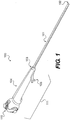
- the device 100 comprises steering mechanism 111 and elongate member 101.
- the steering mechanism includes an actuation system 110 and a housing 104 equipped with one or more ports 105.
- the elongate member 101 includes a proximate end 103 and a distal end 102.
- the actuation system 110 is adapted to control articulation of the distal end 102 of the elongate member 101 along a first plane and a second plane different than the first plane.
- the steering mechanism 111 is adapted to move the distal end of the elongate member along the first plane and the second plane such that 360 degree articulation of the device is achievable. See, e.g., FIGS. 5A-5D , discussed further below.
- the actuation system 110 may be adapted for one-handed operation by a user.
- the actuation system 110 is adapted for one-fingered operation.
- the user may hold or lay the housing 104 of the steering mechanism 111 in his/her hand and manipulate the actuation system 110 with a thumb or finger of the same hand.
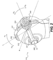
- FIG. 2 An embodiment of the actuation system 110 is shown in FIG. 2 , comprising a first lever 221 and a second lever 231.
- the first lever 221 is fixedly coupled to a distal end of the housing 104 at a first pivot 220 and rotatable, e.g., in directions A 3 and A 4 about axis M.
- Second lever 231 is fixedly coupled to the distal end of the housing 104 at a second pivot 230 and rotatable, e.g., in directions A 1 and A 2 about axis L.
- the first lever 221 and/or the second lever 231 have one end of the lever attached to the housing 104 and an opposite free end.
- the first lever 221 has a first end coupled to the housing 104 at the first pivot 220 and a second free end.
- the second lever 231 has a first end coupled to the housing 104 at the second pivot 230 and an opposite free end.
- each of the first lever 221 and second lever 231 includes a slot, e.g., first slot 222 and second slot 232, respectively, extending along at least a portion of the length of each lever.
- the first and second levers are coupled together via object 240 disposed and slidable within the first and second slots.
- the slots may be closed as shown in FIG. 2 .
- the object 240 may comprise a button configured to slide within the first slot 222 and second slot 232 as shown in FIG. 2 .
- Such a button may have any suitable dimensions, geometry, and/or surface design (e.g., convex or concave) to be useful in single handed operation, including, for example, a generally cylindrical shape.
- Other suitable means of coupling the first lever to the second lever e.g., an object of another form or shape may also be used according to the present disclosure.
- the object 240 may be moved within the first slot 222 to rotate the second lever 231 (e.g., about the second axis L). Similarly, the object 240 may be moved within the second slot 232 to rotate the first lever 221 (e.g., about the first axis M). In addition, the object 240 may be moved within both slots simultaneously to rotate both the first and second levers.
- a user may manipulate the actuation system 110 with a single finger, e.g., the thumb or other finger, by moving the object 240 so as to rotate the first lever 221 and/or second lever 231.
- the housing 104 may be contoured to fit the hand of a user to facilitate operation of the actuation system 110.
- the distal end of the housing 104 may take any form suitable for operation of the actuation system 110 as described herein.
- the distal end of the housing has a curvature, e.g., a spherical shape.
- the first pivot 220 and the second pivot 230 may have substantially the same lateral position but different longitudinal positions as shown in FIGS. 1 and 2 .
- the first pivot and second pivot may also be located at different lateral and longitudinal positions.
- the first and second levers are curved to match the spherical shape of the distal end of the housing 104.
- the object 240 slides within the first slot 222 and/or the second slot 232 of levers 221 and 231, respectively, on the outside of the spherical distal end of the housing 104.
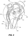
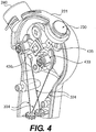
- FIGS. 3 and 4 show views of an actuation system according to the present disclosure with portions of a housing 104 of the actuation system 110 removed, revealing a first cam 322 coupled to the first lever 221 ( FIG. 3 ) and a second cam 433 coupled to the second lever 231 ( FIG. 4 ).
- the first lever 221 is coupled to first cam 322, which in turn is coupled to steering wires 324 that are fixed at the distal end 102 of the device 100.
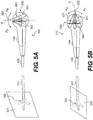
- Rotation of the first lever 221 at the first pivot 220 e.g., about the first axis M directly rotates first cam 322, thus moving steering wires 324 to cause deflection of the distal end portion 102 of the device 100 ( FIG. 1 ) along a first plane. See, e.g., FIG. 5A , discussed below.
- the second lever 231 is coupled to an arm 435 including a protrusion, e.g., a pin or other element, which engages the second cam 433 through an opening 436 formed on the second cam 433.
- the second cam 433 is coupled to steering wires 334 that are fixed at the distal end 102 of the device 100. Rotation of the second lever 231 at the second pivot 230 causes the arm 435 to rotate and engage the second cam 433 with the protrusion by contacting an inside surface of the opening 436. Rotation of the second cam 433 moves steering wires 334 to cause deflection of the distal end portion 102 of the device 100 ( FIG. 1 ) along a second plane different from the first plane. See, e.g., FIG. 5B , discussed below.
- Other suitable mechanisms by which the second lever may engage the second cam are also contemplated consistent with the present disclosure.
- first cam 322 and the second cam 433 are parallel to one another, and are adjacent to each other.
- the object 240 coupled to the first lever 221 and the second lever 231 can be moved to cause deflection of the distal end 102 of the elongate member 101.
- moving the object 240 within the slot defined by the second lever 231 so that the second lever 231 remains stationary causes rotation of the first lever 221 and the first pivot 220 about axis M in directions A 3 and/or A 4 (indicated by the dotted line representations to the left and right of the first lever 221).
- Rotation of the first lever 221 accordingly causes deflection of the distal end 102 of the device 100 along a first plane 501.
- each of the first lever 221 and second lever 231 may be rotated independently of each other such that each of the first cam 322 and second cam 433 may be manipulated independently.
- the first lever 221 and the second lever 231 may be rotated simultaneously as shown in FIG. 5C .
- the object 240 may be moved within both the first slot and the second slot defined by the first lever 221 and the second lever 231, respectively, thus rotating both levers simultaneously.
- the object 240 may be moved in order to engage both the first cam 322 and the second cam 433.
- rotation of both levers causes deflection of the distal end 102 of the device 100 along one or more planes other that the first plane 501 and second plane 502 discussed above with respect to rotating each lever independently.
- moving the object 240 to rotate both the first and second levers allows for deflection of the distal end along two or more planes, such as a plurality of planes, to achieve 360 degree articulation as illustrated in FIG. 5D .
- the first lever 221 and the second lever 231 may be biased toward a starting or neutral position before rotation as shown, for example, in FIG. 2 .
- the first lever 221 and the second lever 231 may be positioned substantially orthogonal to each other.
- the first lever and/or second lever may include a locking mechanism, e.g., to maintain the distal end in a particular configuration.
- the locking mechanism may, for example, be actuated to prevent the object from moving within the slot defined by the first lever, second lever, or both the first lever and second lever, or alternatively may be actuated to allow movement of the lever(s).
- some embodiments may allow one lever to be held in place while the other lever is operated.
- movement of one or both of the first and second levers may be restricted by a friction hold or a ratcheting hold, wherein moving the lever(s) requires a force to overcome the hold.
- one or both of the slots may have, for example, a friction or ratcheting connection to the object.
- surface contact between the underside of the levers and the housing may have, for example, a friction hold or a ratcheting hold.
- the housing 104 of the device 100 may include one or more ports 105 as shown in FIG. 1 .
- the one or more ports 105 may be adapted to be connected to one or more working channels or lumens extending through at least a portion of the elongate member 101 towards the distal end 102 of the device 100.
- the working channels may extend to or towards a treatment site in a body of a patient.
- the one or more ports 105 may be configured to receive medical instrumentation, or aspiration, irrigation, or other fluid conveyance.
- a port 105 may be configured to receive one or more of a guidewire, laser fiber, stone basket, biopsy device, or other medical instrumentation. The port 105 allows a user to insert the medical instrumentation into the working channel and through the elongate member 101 to the treatment site.
Landscapes
- Health & Medical Sciences (AREA)
- Life Sciences & Earth Sciences (AREA)
- Engineering & Computer Science (AREA)
- Animal Behavior & Ethology (AREA)
- Veterinary Medicine (AREA)
- Biophysics (AREA)
- Public Health (AREA)
- Biomedical Technology (AREA)
- Heart & Thoracic Surgery (AREA)
- General Health & Medical Sciences (AREA)
- Anesthesiology (AREA)
- Surgery (AREA)
- Pulmonology (AREA)
- Hematology (AREA)
- Mechanical Engineering (AREA)
- General Engineering & Computer Science (AREA)
- Nuclear Medicine, Radiotherapy & Molecular Imaging (AREA)
- Optics & Photonics (AREA)
- Pathology (AREA)
- Radiology & Medical Imaging (AREA)
- Physics & Mathematics (AREA)
- Medical Informatics (AREA)
- Molecular Biology (AREA)
- Surgical Instruments (AREA)
Claims (11)
- Mécanisme de guidage (111) destiné à être utilisé dans un dispositif médical (100), comprenant :un premier levier qui peut être entraîné en rotation autour d'un premier axe, le premier levier (221) étant couplé à une première came (322) et étant configuré de manière à ce qu'il déplace la première came (322) depuis une première position jusqu'à une seconde position lorsqu'il est entraîné en rotation autour du premier axe de manière à faire fléchir la partie distale ;un second levier (231) qui peut être entraîné en rotation autour d'un second axe, le second levier (231) étant couplé à une seconde came (433) et étant configuré de manière à ce qu'il déplace la seconde came (433) depuis une première position jusqu'à une seconde position lorsqu'il est entraîné en rotation autour du second axe de manière à faire fléchir la partie distale ; dans lequel le premier levier (221) est couplé au second levier (231) ;un logement (104) qui est couplé au premier levier (221) et au second levier (231), le logement (104) comportant une extrémité proximale et une extrémité distale, dans lequel le premier levier (221) et le second levier (231) sont incurvés de manière à ce qu'ils correspondent à une courbure d'une extrémité du logement (104) ; etun objet (240) qui connecte le premier levier (221) au second levier (231), dans lequel le premier levier inclut une première fente (222) et le second levier inclut une seconde fente (232), et l'objet (240) est configuré de manière à ce qu'il coulisse de façon simultanée à l'intérieur de la première fente (222) et à l'intérieur de la seconde fente (232) sur l'extérieur de l'extrémité incurvée du logement de manière à entraîner en rotation le premier levier (221) et/ou le second levier (231) ; dans lequel le premier levier (221) comporte une première extrémité qui est couplée au logement (104) au niveau d'un premier pivot (220) et une seconde extrémité libre ; et dans lequel le second levier (231) comporte une première extrémité qui est couplée au logement (104) au niveau d'un second pivot (230) et une seconde extrémité libre.
- Mécanisme de guidage (111) selon la revendication 1, dans lequel le coulissement à l'intérieur de la première fente (222) a pour effet que le second levier (231) est entraîné en rotation autour du second axe.
- Mécanisme de guidage (111) selon la revendication 1, dans lequel le coulissement à l'intérieur de la seconde fente a pour effet que le premier levier (221) est entraîné en rotation autour du premier axe.
- Mécanisme de guidage (111) selon la revendication 1, dans lequel le premier levier (221) est configuré de manière à ce qu'il soit déplacé de façon indépendante du second levier (231) et le second levier (231) est configuré de manière à ce qu'il soit déplacé de façon indépendante du premier levier (221).
- Mécanisme de guidage (111) selon la revendication 1, comprenant en outre un bras (435) qui est couplé au second levier (231), le bras (435) étant adapté de manière à ce qu'il engage une partie de la seconde came (433) lorsque le second levier (231) est entraîné en rotation autour du second axe.
- Mécanisme de guidage (111) selon la revendication 5, dans lequel le bras (435) inclut une protubérance qui s'étend au moins partiellement au travers d'une ouverture (436) qui est formée sur la seconde came (433).
- Mécanisme de guidage (111) selon la revendication 1, dans lequel l'objet (240) inclut un bouton qui peut coulisser à l'intérieur de la première fente (222) qui est ménagée dans le premier levier (221) et à l'intérieur de la seconde fente (232) qui est ménagée dans le second levier (231) ; dans lequel la première fente (222) et la seconde fente (232) sont fermées.
- Mécanisme de guidage (111) selon la revendication 1, dans lequel l'extrémité distale du logement (104) présente une forme sphérique.
- Mécanisme de guidage (111) selon la revendication 8, dans lequel le premier levier (221) et le second levier (231) sont incurvés de manière à ce qu'ils correspondent à la forme sphérique de l'extrémité distale du logement (104).
- Mécanisme de guidage (111) selon l'une des revendications 8 ou 9, dans lequel l'objet (240) est configuré de manière à ce qu'il coulisse à l'intérieur de la première fente (222) du premier levier (221) et/ou à l'intérieur de la seconde fente (232) du second levier (231) sur l'extérieur de l'extrémité distale sphérique du logement (104).
- Mécanisme de guidage (111) selon l'une des revendications qui précèdent, dans lequel le premier pivot (220) et le second pivot (230) présentent la même position latérale mais des positions longitudinales différentes.
Priority Applications (1)
| Application Number | Priority Date | Filing Date | Title |
|---|---|---|---|
| EP19152187.1A EP3505043B1 (fr) | 2013-03-11 | 2014-03-06 | Mécanisme de fléchissement |
Applications Claiming Priority (2)
| Application Number | Priority Date | Filing Date | Title |
|---|---|---|---|
| US201361776152P | 2013-03-11 | 2013-03-11 | |
| PCT/US2014/021234 WO2014164208A1 (fr) | 2013-03-11 | 2014-03-06 | Mécanisme de fléchissement |
Related Child Applications (2)
| Application Number | Title | Priority Date | Filing Date |
|---|---|---|---|
| EP19152187.1A Division-Into EP3505043B1 (fr) | 2013-03-11 | 2014-03-06 | Mécanisme de fléchissement |
| EP19152187.1A Division EP3505043B1 (fr) | 2013-03-11 | 2014-03-06 | Mécanisme de fléchissement |
Publications (2)
| Publication Number | Publication Date |
|---|---|
| EP2967281A1 EP2967281A1 (fr) | 2016-01-20 |
| EP2967281B1 true EP2967281B1 (fr) | 2019-03-06 |
Family
ID=50346169
Family Applications (2)
| Application Number | Title | Priority Date | Filing Date |
|---|---|---|---|
| EP14712147.9A Not-in-force EP2967281B1 (fr) | 2013-03-11 | 2014-03-06 | Mécanisme de fléchissement |
| EP19152187.1A Not-in-force EP3505043B1 (fr) | 2013-03-11 | 2014-03-06 | Mécanisme de fléchissement |
Family Applications After (1)
| Application Number | Title | Priority Date | Filing Date |
|---|---|---|---|
| EP19152187.1A Not-in-force EP3505043B1 (fr) | 2013-03-11 | 2014-03-06 | Mécanisme de fléchissement |
Country Status (3)
| Country | Link |
|---|---|
| US (4) | US9657817B2 (fr) |
| EP (2) | EP2967281B1 (fr) |
| WO (1) | WO2014164208A1 (fr) |
Families Citing this family (126)
| Publication number | Priority date | Publication date | Assignee | Title |
|---|---|---|---|---|
| WO2006097931A2 (fr) | 2005-03-17 | 2006-09-21 | Valtech Cardio, Ltd. | Techniques de traitement de la valve mitrale |
| US9883943B2 (en) | 2006-12-05 | 2018-02-06 | Valtech Cardio, Ltd. | Implantation of repair devices in the heart |
| US11259924B2 (en) | 2006-12-05 | 2022-03-01 | Valtech Cardio Ltd. | Implantation of repair devices in the heart |
| US11660190B2 (en) | 2007-03-13 | 2023-05-30 | Edwards Lifesciences Corporation | Tissue anchors, systems and methods, and devices |
| US9579126B2 (en) | 2008-02-02 | 2017-02-28 | Globus Medical, Inc. | Spinal rod link reducer |
| US8382829B1 (en) | 2008-03-10 | 2013-02-26 | Mitralign, Inc. | Method to reduce mitral regurgitation by cinching the commissure of the mitral valve |
| US8652202B2 (en) | 2008-08-22 | 2014-02-18 | Edwards Lifesciences Corporation | Prosthetic heart valve and delivery apparatus |
| US10517719B2 (en) | 2008-12-22 | 2019-12-31 | Valtech Cardio, Ltd. | Implantation of repair devices in the heart |
| US8715342B2 (en) | 2009-05-07 | 2014-05-06 | Valtech Cardio, Ltd. | Annuloplasty ring with intra-ring anchoring |
| US8545553B2 (en) | 2009-05-04 | 2013-10-01 | Valtech Cardio, Ltd. | Over-wire rotation tool |
| EP3848002A1 (fr) | 2008-12-22 | 2021-07-14 | Valtech Cardio, Ltd. | Dispositifs d'annuloplastie réglables et mécanismes de réglage associés |
| US8241351B2 (en) | 2008-12-22 | 2012-08-14 | Valtech Cardio, Ltd. | Adjustable partial annuloplasty ring and mechanism therefor |
| US8353956B2 (en) | 2009-02-17 | 2013-01-15 | Valtech Cardio, Ltd. | Actively-engageable movement-restriction mechanism for use with an annuloplasty structure |
| US9968452B2 (en) | 2009-05-04 | 2018-05-15 | Valtech Cardio, Ltd. | Annuloplasty ring delivery cathethers |
| US12485010B2 (en) | 2009-05-07 | 2025-12-02 | Edwards Lifesciences Innovation (Israel) Ltd. | Multiple anchor delivery tool |
| US10098737B2 (en) | 2009-10-29 | 2018-10-16 | Valtech Cardio, Ltd. | Tissue anchor for annuloplasty device |
| US9180007B2 (en) | 2009-10-29 | 2015-11-10 | Valtech Cardio, Ltd. | Apparatus and method for guide-wire based advancement of an adjustable implant |
| US8734467B2 (en) | 2009-12-02 | 2014-05-27 | Valtech Cardio, Ltd. | Delivery tool for implantation of spool assembly coupled to a helical anchor |
| US8449599B2 (en) | 2009-12-04 | 2013-05-28 | Edwards Lifesciences Corporation | Prosthetic valve for replacing mitral valve |
| US10792152B2 (en) | 2011-06-23 | 2020-10-06 | Valtech Cardio, Ltd. | Closed band for percutaneous annuloplasty |
| EP2723274B1 (fr) | 2011-06-23 | 2017-12-27 | Valtech Cardio, Ltd. | Élément de fermeture utilisable avec une structure d'annuloplastie |
| US8858623B2 (en) | 2011-11-04 | 2014-10-14 | Valtech Cardio, Ltd. | Implant having multiple rotational assemblies |
| EP3970627B1 (fr) | 2011-11-08 | 2023-12-20 | Edwards Lifesciences Innovation (Israel) Ltd. | Fonction d'orientation commandée d'un outil de pose d'implant |
| CN104203157B (zh) | 2011-12-12 | 2016-02-03 | 戴维·阿隆 | 心脏瓣膜修补器械 |
| CA2885354A1 (fr) | 2012-09-29 | 2014-04-03 | Mitralign, Inc. | Systeme de distribution de verrous de plicature et procede d'utilisation de celui-ci |
| WO2014064694A2 (fr) | 2012-10-23 | 2014-05-01 | Valtech Cardio, Ltd. | Fonctionnalité d'orientation commandée pour outil de pose d'implant |
| US10376266B2 (en) | 2012-10-23 | 2019-08-13 | Valtech Cardio, Ltd. | Percutaneous tissue anchor techniques |
| WO2014087402A1 (fr) | 2012-12-06 | 2014-06-12 | Valtech Cardio, Ltd. | Techniques pour l'avancée par fil-guide d'un outil |
| US9439763B2 (en) | 2013-02-04 | 2016-09-13 | Edwards Lifesciences Corporation | Prosthetic valve for replacing mitral valve |
| EP2961351B1 (fr) | 2013-02-26 | 2018-11-28 | Mitralign, Inc. | Dispositif pour réparation percutanée de valve tricuspide |
| US10449333B2 (en) | 2013-03-14 | 2019-10-22 | Valtech Cardio, Ltd. | Guidewire feeder |
| WO2014152503A1 (fr) | 2013-03-15 | 2014-09-25 | Mitralign, Inc. | Cathéters de translation, systèmes et leurs procédés d'utilisation |
| US10070857B2 (en) | 2013-08-31 | 2018-09-11 | Mitralign, Inc. | Devices and methods for locating and implanting tissue anchors at mitral valve commissure |
| US10299793B2 (en) | 2013-10-23 | 2019-05-28 | Valtech Cardio, Ltd. | Anchor magazine |
| US9622863B2 (en) | 2013-11-22 | 2017-04-18 | Edwards Lifesciences Corporation | Aortic insufficiency repair device and method |
| US9610162B2 (en) | 2013-12-26 | 2017-04-04 | Valtech Cardio, Ltd. | Implantation of flexible implant |
| US9744335B2 (en) | 2014-07-01 | 2017-08-29 | Auris Surgical Robotics, Inc. | Apparatuses and methods for monitoring tendons of steerable catheters |
| US9561083B2 (en) | 2014-07-01 | 2017-02-07 | Auris Surgical Robotics, Inc. | Articulating flexible endoscopic tool with roll capabilities |
| EP3206629B1 (fr) | 2014-10-14 | 2021-07-14 | Valtech Cardio, Ltd. | Dispositif de retenue de feuillets de valve cardiaque |
| CN111437068B (zh) | 2014-12-04 | 2023-01-17 | 爱德华兹生命科学公司 | 用于修复心脏瓣膜的经皮夹具 |
| US20160256269A1 (en) | 2015-03-05 | 2016-09-08 | Mitralign, Inc. | Devices for treating paravalvular leakage and methods use thereof |
| US11819636B2 (en) | 2015-03-30 | 2023-11-21 | Auris Health, Inc. | Endoscope pull wire electrical circuit |
| EP3288496B1 (fr) | 2015-04-30 | 2024-05-29 | Edwards Lifesciences Innovation (Israel) Ltd. | Technologies d'annuloplastie |
| ES3001450T3 (en) | 2015-05-14 | 2025-03-05 | Edwards Lifesciences Corp | Heart valve sealing devices and delivery devices therefor |
| WO2017117370A2 (fr) | 2015-12-30 | 2017-07-06 | Mitralign, Inc. | Système et procédé de réduction de régurgitation tricuspide |
| US10799676B2 (en) * | 2016-03-21 | 2020-10-13 | Edwards Lifesciences Corporation | Multi-direction steerable handles for steering catheters |
| US10799677B2 (en) | 2016-03-21 | 2020-10-13 | Edwards Lifesciences Corporation | Multi-direction steerable handles for steering catheters |
| US11219746B2 (en) | 2016-03-21 | 2022-01-11 | Edwards Lifesciences Corporation | Multi-direction steerable handles for steering catheters |
| US10835714B2 (en) | 2016-03-21 | 2020-11-17 | Edwards Lifesciences Corporation | Multi-direction steerable handles for steering catheters |
| US10799675B2 (en) | 2016-03-21 | 2020-10-13 | Edwards Lifesciences Corporation | Cam controlled multi-direction steerable handles |
| US10383663B2 (en) | 2016-03-29 | 2019-08-20 | Globus Medical, Inc. | Revision connectors, systems and methods thereof |
| US9980755B2 (en) | 2016-03-29 | 2018-05-29 | Globus Medical, Inc. | Revision connectors, systems, and methods thereof |
| US10624679B2 (en) | 2016-03-29 | 2020-04-21 | Globus Medical, Inc. | Revision connectors, systems and methods thereof |
| US10307185B2 (en) | 2016-03-29 | 2019-06-04 | Globus Medical, Inc. | Revision connectors, systems, and methods thereof |
| US10702274B2 (en) | 2016-05-26 | 2020-07-07 | Edwards Lifesciences Corporation | Method and system for closing left atrial appendage |
| US10973638B2 (en) | 2016-07-07 | 2021-04-13 | Edwards Lifesciences Corporation | Device and method for treating vascular insufficiency |
| GB201611910D0 (en) | 2016-07-08 | 2016-08-24 | Valtech Cardio Ltd | Adjustable annuloplasty device with alternating peaks and troughs |
| US10653862B2 (en) | 2016-11-07 | 2020-05-19 | Edwards Lifesciences Corporation | Apparatus for the introduction and manipulation of multiple telescoping catheters |
| US10905554B2 (en) | 2017-01-05 | 2021-02-02 | Edwards Lifesciences Corporation | Heart valve coaptation device |
| JP3215550U (ja) * | 2017-01-25 | 2018-03-29 | 珠海嘉潤医用影像科技有限公司Zhuhai Kaden Medical Imaging Technology Co., Ltd | 気管支鏡の引張コードのための制御機構 |
| US11045627B2 (en) | 2017-04-18 | 2021-06-29 | Edwards Lifesciences Corporation | Catheter system with linear actuation control mechanism |
| US11224511B2 (en) | 2017-04-18 | 2022-01-18 | Edwards Lifesciences Corporation | Heart valve sealing devices and delivery devices therefor |
| PL3558169T3 (pl) | 2017-04-18 | 2022-04-04 | Edwards Lifesciences Corporation | Urządzenia do uszczelniania zastawki serca i urządzenia do ich doprowadzania |
| US10799312B2 (en) | 2017-04-28 | 2020-10-13 | Edwards Lifesciences Corporation | Medical device stabilizing apparatus and method of use |
| US10959846B2 (en) | 2017-05-10 | 2021-03-30 | Edwards Lifesciences Corporation | Mitral valve spacer device |
| NL2019146B1 (en) * | 2017-06-29 | 2019-01-14 | Deam Holding B V | Medical device with flexible tip |
| PL422397A1 (pl) * | 2017-07-29 | 2019-02-11 | Endoscope Spółka Z Ograniczoną Odpowiedzialnością | Układ do sterowania końcówką sondy medycznej, zwłaszcza sondy endoskopu oraz uchwyt endoskopu |
| US11051940B2 (en) | 2017-09-07 | 2021-07-06 | Edwards Lifesciences Corporation | Prosthetic spacer device for heart valve |
| US11065117B2 (en) | 2017-09-08 | 2021-07-20 | Edwards Lifesciences Corporation | Axisymmetric adjustable device for treating mitral regurgitation |
| US11110251B2 (en) | 2017-09-19 | 2021-09-07 | Edwards Lifesciences Corporation | Multi-direction steerable handles for steering catheters |
| CN111200962A (zh) * | 2017-10-11 | 2020-05-26 | 奥林巴斯株式会社 | 内窥镜用操作线牵拉装置 |
| US10835221B2 (en) | 2017-11-02 | 2020-11-17 | Valtech Cardio, Ltd. | Implant-cinching devices and systems |
| US11135062B2 (en) | 2017-11-20 | 2021-10-05 | Valtech Cardio Ltd. | Cinching of dilated heart muscle |
| US10238493B1 (en) | 2018-01-09 | 2019-03-26 | Edwards Lifesciences Corporation | Native valve repair devices and procedures |
| US10231837B1 (en) | 2018-01-09 | 2019-03-19 | Edwards Lifesciences Corporation | Native valve repair devices and procedures |
| US10973639B2 (en) | 2018-01-09 | 2021-04-13 | Edwards Lifesciences Corporation | Native valve repair devices and procedures |
| US10105222B1 (en) | 2018-01-09 | 2018-10-23 | Edwards Lifesciences Corporation | Native valve repair devices and procedures |
| US10076415B1 (en) | 2018-01-09 | 2018-09-18 | Edwards Lifesciences Corporation | Native valve repair devices and procedures |
| US10136993B1 (en) | 2018-01-09 | 2018-11-27 | Edwards Lifesciences Corporation | Native valve repair devices and procedures |
| US10123873B1 (en) | 2018-01-09 | 2018-11-13 | Edwards Lifesciences Corporation | Native valve repair devices and procedures |
| JP7343393B2 (ja) | 2018-01-09 | 2023-09-12 | エドワーズ ライフサイエンシーズ コーポレイション | 天然心臓弁修復装置および処置 |
| US10159570B1 (en) | 2018-01-09 | 2018-12-25 | Edwards Lifesciences Corporation | Native valve repair devices and procedures |
| US10245144B1 (en) | 2018-01-09 | 2019-04-02 | Edwards Lifesciences Corporation | Native valve repair devices and procedures |
| US10111751B1 (en) | 2018-01-09 | 2018-10-30 | Edwards Lifesciences Corporation | Native valve repair devices and procedures |
| CN111655200B (zh) | 2018-01-24 | 2023-07-14 | 爱德华兹生命科学创新(以色列)有限公司 | 瓣环成形术结构的收缩 |
| WO2019145941A1 (fr) | 2018-01-26 | 2019-08-01 | Valtech Cardio, Ltd. | Techniques pour faciliter la fixation de valve cardiaque et le remplacement de cordon |
| US11389297B2 (en) | 2018-04-12 | 2022-07-19 | Edwards Lifesciences Corporation | Mitral valve spacer device |
| US11207181B2 (en) | 2018-04-18 | 2021-12-28 | Edwards Lifesciences Corporation | Heart valve sealing devices and delivery devices therefor |
| JP7387731B2 (ja) | 2018-07-12 | 2023-11-28 | エドワーズ ライフサイエンシーズ イノベーション (イスラエル) リミテッド | 弁輪形成システムおよびそのための係止ツール |
| US10945844B2 (en) | 2018-10-10 | 2021-03-16 | Edwards Lifesciences Corporation | Heart valve sealing devices and delivery devices therefor |
| EP3883500B1 (fr) | 2018-11-20 | 2024-11-06 | Edwards Lifesciences Corporation | Outils de déploiement de pose d'un dispositif sur une valvule cardiaque native |
| CN113301869A (zh) | 2018-11-21 | 2021-08-24 | 爱德华兹生命科学公司 | 心脏瓣膜密封装置、其递送装置以及取回装置 |
| CR20210312A (es) | 2018-11-29 | 2021-09-14 | Edwards Lifesciences Corp | Método y aparato de cateterización |
| CN113747858B (zh) | 2019-02-11 | 2024-11-01 | 爱德华兹生命科学公司 | 心脏瓣膜密封装置及其递送装置 |
| WO2020168081A1 (fr) | 2019-02-14 | 2020-08-20 | Edwards Lifesciences Corporation | Dispositifs d'étanchéité de valve cardiaque et dispositifs de distribution pour ceux-ci |
| SG11202108606PA (en) | 2019-02-25 | 2021-09-29 | Edwards Lifesciences Corp | Heart valve sealing devices |
| JP7061584B2 (ja) * | 2019-03-20 | 2022-04-28 | 富士フイルム株式会社 | 内視鏡 |
| AU2020284630A1 (en) | 2019-05-29 | 2021-11-18 | Edwards Lifesciences Innovation (Israel) Ltd. | Tissue anchor handling systems and methods |
| US12502167B2 (en) | 2019-07-16 | 2025-12-23 | Edwards Lifesciences Corporation | Tissue remodeling systems and methods |
| WO2021014440A2 (fr) | 2019-07-23 | 2021-01-28 | Valtech Cardio, Ltd. | Contraction d'une structure d'annuloplastie |
| US12364606B2 (en) | 2019-07-23 | 2025-07-22 | Edwards Lifesciences Innovation (Israel) Ltd. | Fluoroscopic visualization of heart valve anatomy |
| CN114258313A (zh) | 2019-08-28 | 2022-03-29 | 瓦尔泰克卡迪欧有限公司 | 低剖面可转向导管 |
| JP2022546160A (ja) | 2019-08-30 | 2022-11-04 | エドワーズ ライフサイエンシーズ イノベーション (イスラエル) リミテッド | アンカーチャネル先端 |
| KR20220066398A (ko) | 2019-09-25 | 2022-05-24 | 카디악 임플란츠 엘엘씨 | 심장 판막 고리 감소 시스템 |
| WO2021070389A1 (fr) * | 2019-10-11 | 2021-04-15 | オリンパス株式会社 | Mécanisme d'opération de flexion pour endoscope |
| CA3143014A1 (fr) | 2019-10-15 | 2021-04-22 | Edwards Lifesciences Corporation | Dispositifs d'etancheite de valve cardiaque et dispositifs de distribution associes |
| WO2021084407A1 (fr) | 2019-10-29 | 2021-05-06 | Valtech Cardio, Ltd. | Technologies d'ancrage d'annuloplastie et de tissu |
| US20220392065A1 (en) | 2020-01-07 | 2022-12-08 | Cleerly, Inc. | Systems, methods, and devices for medical image analysis, diagnosis, risk stratification, decision making and/or disease tracking |
| US11969280B2 (en) | 2020-01-07 | 2024-04-30 | Cleerly, Inc. | Systems, methods, and devices for medical image analysis, diagnosis, risk stratification, decision making and/or disease tracking |
| US11501436B2 (en) | 2020-01-07 | 2022-11-15 | Cleerly, Inc. | Systems, methods, and devices for medical image analysis, diagnosis, risk stratification, decision making and/or disease tracking |
| EP4090223B1 (fr) * | 2020-01-15 | 2025-06-25 | Entellect Medical Holdings | Poignée de commande d'endoscope dotée d'un ensemble de guidage |
| EP4096529B1 (fr) | 2020-03-23 | 2025-05-07 | Edwards Lifesciences Innovation (Israel) Ltd. | Treuil autobloquant |
| WO2021236634A2 (fr) | 2020-05-20 | 2021-11-25 | Cardiac Implants, Llc | Réduction du diamètre d'un anneau valvulaire cardiaque avec commande indépendante sur chacun des ancrages qui sont lancés dans l'anneau |
| JP7766052B2 (ja) * | 2020-06-11 | 2025-11-07 | ボストン サイエンティフィック メディカル デバイス リミテッド | 医療システム、機器、及び関連する方法 |
| CA3182316A1 (fr) | 2020-06-19 | 2021-12-23 | Edwards Lifesciences Innovation (Israel) Ltd. | Ancres pour tissu a arret automatique |
| WO2022051241A1 (fr) | 2020-09-01 | 2022-03-10 | Edwards Lifesciences Corporation | Systèmes de stabilisation de dispositif médical |
| US12310558B2 (en) * | 2020-09-22 | 2025-05-27 | Boston Scientific Limited | Medical articulation devices and methods of using the same |
| CA3213848A1 (fr) * | 2021-03-24 | 2022-09-29 | Boston Scientific Scimed, Inc. | Poignee d'endoscope et dispositif de deploiement |
| JP7840987B2 (ja) | 2021-10-05 | 2026-04-06 | シーメンス ヘルシニアーズ エンドバスキュラー ロボティクス インコーポレイテッド | 細長い医療デバイスのロボット制御 |
| US20250143657A1 (en) | 2022-03-10 | 2025-05-08 | Cleerly, Inc. | Systems, devices, and methods for non-invasive image-based plaque analysis and risk determination |
| US20250217981A1 (en) | 2022-03-10 | 2025-07-03 | Cleerly, Inc. | Systems, methods, and devices for image-based plaque analysis and risk determination |
| US12406365B2 (en) | 2022-03-10 | 2025-09-02 | Cleerly, Inc. | Systems, devices, and methods for non-invasive image-based plaque analysis and risk determination |
| US12440180B2 (en) | 2022-03-10 | 2025-10-14 | Cleerly, Inc. | Systems, devices, and methods for non-invasive image-based plaque analysis and risk determination |
| CN114947702B (zh) * | 2022-05-25 | 2023-05-26 | 湖南省华芯医疗器械有限公司 | 一种内窥镜手柄的可抛弃段、内窥镜手柄及内窥镜 |
| CN114795069B (zh) * | 2022-05-25 | 2023-03-24 | 湖南省华芯医疗器械有限公司 | 一种内窥镜手柄的可抛弃段、内窥镜手柄及内窥镜 |
| USD1071198S1 (en) | 2023-06-28 | 2025-04-15 | Edwards Lifesciences Corporation | Cradle |
Citations (2)
| Publication number | Priority date | Publication date | Assignee | Title |
|---|---|---|---|---|
| EP0077526A2 (fr) * | 1981-10-15 | 1983-04-27 | Olympus Optical Co., Ltd. | Système endoscopique à articulation commandé électriquement |
| EP0079525A1 (fr) * | 1981-11-04 | 1983-05-25 | Olympus Optical Co., Ltd. | Appareil endoscopique avec un mécanisme de flexion électrique |
Family Cites Families (26)
| Publication number | Priority date | Publication date | Assignee | Title |
|---|---|---|---|---|
| US2453862A (en) * | 1947-06-02 | 1948-11-16 | Salisbury Peter Frederic | Gastroscope |
| US4620176A (en) | 1984-09-25 | 1986-10-28 | Hayes Charles L | Control stick mechanism |
| US4721099A (en) * | 1985-10-30 | 1988-01-26 | Kabushiki Kaisha Machida Seisakusho | Operating mechanism for bendable section of endoscope |
| US5325845A (en) * | 1992-06-08 | 1994-07-05 | Adair Edwin Lloyd | Steerable sheath for use with selected removable optical catheter |
| US5347989A (en) | 1992-09-11 | 1994-09-20 | Welch Allyn, Inc. | Control mechanism for steerable elongated probe having a sealed joystick |
| EP0955860A1 (fr) | 1995-06-07 | 1999-11-17 | Robert T. Chilcoat | Endoscope articule offrant des avantages specifiques en laryngoscopie |
| US5589854A (en) | 1995-06-22 | 1996-12-31 | Tsai; Ming-Chang | Touching feedback device |
| US6123699A (en) | 1997-09-05 | 2000-09-26 | Cordis Webster, Inc. | Omni-directional steerable catheter |
| US7285117B2 (en) | 2002-03-15 | 2007-10-23 | Boston Scientific Scimed, Inc. | Medical device control systems |
| US20040059191A1 (en) * | 2002-06-17 | 2004-03-25 | Robert Krupa | Mechanical steering mechanism for borescopes, endoscopes, catheters, guide tubes, and working tools |
| US20040193016A1 (en) * | 2002-06-17 | 2004-09-30 | Thomas Root | Endoscopic delivery system for the non-destructive testing and evaluation of remote flaws |
| US8012100B2 (en) | 2002-10-01 | 2011-09-06 | Boston Scientific Scimed, Inc. | Fluid pressure-actuated medical device |
| US7682358B2 (en) | 2003-10-30 | 2010-03-23 | Medtronic, Inc. | Steerable catheter |
| US8287449B2 (en) * | 2005-05-26 | 2012-10-16 | Ars Co., Ltd. | Endoscope device |
| EP2021063B1 (fr) * | 2006-05-19 | 2013-05-15 | Boston Scientific Limited | Mécanisme de commande pour dispositif médical orientable |
| US7615067B2 (en) | 2006-06-05 | 2009-11-10 | Cambridge Endoscopic Devices, Inc. | Surgical instrument |
| EP4233962B1 (fr) * | 2007-05-18 | 2025-11-05 | Boston Scientific Scimed, Inc. | Systèmes d'entraînement médicaux |
| US8048024B2 (en) * | 2008-03-17 | 2011-11-01 | Boston Scientific Scimed, Inc. | Steering mechanism |
| US9101735B2 (en) * | 2008-07-07 | 2015-08-11 | Intuitive Surgical Operations, Inc. | Catheter control systems |
| US8048025B2 (en) * | 2008-07-07 | 2011-11-01 | Boston Scientific Scimed, Inc. | Multi-plane motion control mechanism |
| US8834357B2 (en) | 2008-11-12 | 2014-09-16 | Boston Scientific Scimed, Inc. | Steering mechanism |
| US8790250B2 (en) * | 2008-12-10 | 2014-07-29 | Ambu A/S | Endoscope bending section control mechanism |
| JP4755732B2 (ja) * | 2009-10-30 | 2011-08-24 | オリンパスメディカルシステムズ株式会社 | 内視鏡 |
| EP2532297B1 (fr) * | 2010-04-28 | 2016-04-20 | Olympus Corporation | Mécanisme d'actionnement, endoscope et cathéter de guidage |
| US8177710B1 (en) * | 2011-08-02 | 2012-05-15 | Olympus Corporation | Endoscopic device |
| WO2013106444A1 (fr) * | 2012-01-10 | 2013-07-18 | Boston Scientific Scimed, Inc. | Dispositif médical orientable ayant un système d'imagerie |
-
2014
- 2014-03-06 EP EP14712147.9A patent/EP2967281B1/fr not_active Not-in-force
- 2014-03-06 US US14/199,287 patent/US9657817B2/en not_active Expired - Fee Related
- 2014-03-06 EP EP19152187.1A patent/EP3505043B1/fr not_active Not-in-force
- 2014-03-06 WO PCT/US2014/021234 patent/WO2014164208A1/fr not_active Ceased
-
2017
- 2017-04-19 US US15/491,535 patent/US10234002B2/en active Active
-
2019
- 2019-02-05 US US16/267,938 patent/US10487924B2/en active Active
- 2019-10-18 US US16/657,382 patent/US11187307B2/en active Active
Patent Citations (2)
| Publication number | Priority date | Publication date | Assignee | Title |
|---|---|---|---|---|
| EP0077526A2 (fr) * | 1981-10-15 | 1983-04-27 | Olympus Optical Co., Ltd. | Système endoscopique à articulation commandé électriquement |
| EP0079525A1 (fr) * | 1981-11-04 | 1983-05-25 | Olympus Optical Co., Ltd. | Appareil endoscopique avec un mécanisme de flexion électrique |
Also Published As
| Publication number | Publication date |
|---|---|
| US11187307B2 (en) | 2021-11-30 |
| EP3505043B1 (fr) | 2020-11-25 |
| US10487924B2 (en) | 2019-11-26 |
| US9657817B2 (en) | 2017-05-23 |
| EP2967281A1 (fr) | 2016-01-20 |
| US20140251042A1 (en) | 2014-09-11 |
| WO2014164208A1 (fr) | 2014-10-09 |
| US20200049234A1 (en) | 2020-02-13 |
| US10234002B2 (en) | 2019-03-19 |
| EP3505043A1 (fr) | 2019-07-03 |
| US20190170227A1 (en) | 2019-06-06 |
| US20170268639A1 (en) | 2017-09-21 |
Similar Documents
| Publication | Publication Date | Title |
|---|---|---|
| US11187307B2 (en) | Deflection mechanism | |
| US8048025B2 (en) | Multi-plane motion control mechanism | |
| US10039436B2 (en) | Steering mechanism | |
| EP2355885B1 (fr) | Mécanisme de guidage | |
| US9375550B2 (en) | Catheter actuators providing mechanical advantage | |
| EP3013403B1 (fr) | Cathéter à mécanisme de retour actif en position rectiligne | |
| WO2009117696A1 (fr) | Guide d'outil orientable pour utilisation avec des dispositifs médicaux endoscopiques souples | |
| US12256900B2 (en) | Ureteroscope device and method for using of such a device | |
| US20140379014A1 (en) | Endoscopic Instrument | |
| US20240408356A1 (en) | Catheter handle controlling multiple degrees of freedom of a set of nested catheters |
Legal Events
| Date | Code | Title | Description |
|---|---|---|---|
| PUAI | Public reference made under article 153(3) epc to a published international application that has entered the european phase |
Free format text: ORIGINAL CODE: 0009012 |
|
| 17P | Request for examination filed |
Effective date: 20151005 |
|
| AK | Designated contracting states |
Kind code of ref document: A1 Designated state(s): AL AT BE BG CH CY CZ DE DK EE ES FI FR GB GR HR HU IE IS IT LI LT LU LV MC MK MT NL NO PL PT RO RS SE SI SK SM TR |
|
| AX | Request for extension of the european patent |
Extension state: BA ME |
|
| DAX | Request for extension of the european patent (deleted) | ||
| STAA | Information on the status of an ep patent application or granted ep patent |
Free format text: STATUS: EXAMINATION IS IN PROGRESS |
|
| 17Q | First examination report despatched |
Effective date: 20170928 |
|
| GRAP | Despatch of communication of intention to grant a patent |
Free format text: ORIGINAL CODE: EPIDOSNIGR1 |
|
| STAA | Information on the status of an ep patent application or granted ep patent |
Free format text: STATUS: GRANT OF PATENT IS INTENDED |
|
| INTG | Intention to grant announced |
Effective date: 20180921 |
|
| GRAS | Grant fee paid |
Free format text: ORIGINAL CODE: EPIDOSNIGR3 |
|
| GRAA | (expected) grant |
Free format text: ORIGINAL CODE: 0009210 |
|
| STAA | Information on the status of an ep patent application or granted ep patent |
Free format text: STATUS: THE PATENT HAS BEEN GRANTED |
|
| AK | Designated contracting states |
Kind code of ref document: B1 Designated state(s): AL AT BE BG CH CY CZ DE DK EE ES FI FR GB GR HR HU IE IS IT LI LT LU LV MC MK MT NL NO PL PT RO RS SE SI SK SM TR |
|
| REG | Reference to a national code |
Ref country code: GB Ref legal event code: FG4D |
|
| REG | Reference to a national code |
Ref country code: CH Ref legal event code: EP Ref country code: AT Ref legal event code: REF Ref document number: 1103459 Country of ref document: AT Kind code of ref document: T Effective date: 20190315 |
|
| REG | Reference to a national code |
Ref country code: DE Ref legal event code: R096 Ref document number: 602014042278 Country of ref document: DE |
|
| REG | Reference to a national code |
Ref country code: IE Ref legal event code: FG4D |
|
| REG | Reference to a national code |
Ref country code: NL Ref legal event code: MP Effective date: 20190306 |
|
| REG | Reference to a national code |
Ref country code: LT Ref legal event code: MG4D |
|
| PG25 | Lapsed in a contracting state [announced via postgrant information from national office to epo] |
Ref country code: LT Free format text: LAPSE BECAUSE OF FAILURE TO SUBMIT A TRANSLATION OF THE DESCRIPTION OR TO PAY THE FEE WITHIN THE PRESCRIBED TIME-LIMIT Effective date: 20190306 Ref country code: SE Free format text: LAPSE BECAUSE OF FAILURE TO SUBMIT A TRANSLATION OF THE DESCRIPTION OR TO PAY THE FEE WITHIN THE PRESCRIBED TIME-LIMIT Effective date: 20190306 Ref country code: NO Free format text: LAPSE BECAUSE OF FAILURE TO SUBMIT A TRANSLATION OF THE DESCRIPTION OR TO PAY THE FEE WITHIN THE PRESCRIBED TIME-LIMIT Effective date: 20190606 Ref country code: FI Free format text: LAPSE BECAUSE OF FAILURE TO SUBMIT A TRANSLATION OF THE DESCRIPTION OR TO PAY THE FEE WITHIN THE PRESCRIBED TIME-LIMIT Effective date: 20190306 |
|
| PG25 | Lapsed in a contracting state [announced via postgrant information from national office to epo] |
Ref country code: GR Free format text: LAPSE BECAUSE OF FAILURE TO SUBMIT A TRANSLATION OF THE DESCRIPTION OR TO PAY THE FEE WITHIN THE PRESCRIBED TIME-LIMIT Effective date: 20190607 Ref country code: BG Free format text: LAPSE BECAUSE OF FAILURE TO SUBMIT A TRANSLATION OF THE DESCRIPTION OR TO PAY THE FEE WITHIN THE PRESCRIBED TIME-LIMIT Effective date: 20190606 Ref country code: RS Free format text: LAPSE BECAUSE OF FAILURE TO SUBMIT A TRANSLATION OF THE DESCRIPTION OR TO PAY THE FEE WITHIN THE PRESCRIBED TIME-LIMIT Effective date: 20190306 Ref country code: LV Free format text: LAPSE BECAUSE OF FAILURE TO SUBMIT A TRANSLATION OF THE DESCRIPTION OR TO PAY THE FEE WITHIN THE PRESCRIBED TIME-LIMIT Effective date: 20190306 Ref country code: NL Free format text: LAPSE BECAUSE OF FAILURE TO SUBMIT A TRANSLATION OF THE DESCRIPTION OR TO PAY THE FEE WITHIN THE PRESCRIBED TIME-LIMIT Effective date: 20190306 Ref country code: HR Free format text: LAPSE BECAUSE OF FAILURE TO SUBMIT A TRANSLATION OF THE DESCRIPTION OR TO PAY THE FEE WITHIN THE PRESCRIBED TIME-LIMIT Effective date: 20190306 |
|
| REG | Reference to a national code |
Ref country code: AT Ref legal event code: MK05 Ref document number: 1103459 Country of ref document: AT Kind code of ref document: T Effective date: 20190306 |
|
| PG25 | Lapsed in a contracting state [announced via postgrant information from national office to epo] |
Ref country code: IT Free format text: LAPSE BECAUSE OF FAILURE TO SUBMIT A TRANSLATION OF THE DESCRIPTION OR TO PAY THE FEE WITHIN THE PRESCRIBED TIME-LIMIT Effective date: 20190306 Ref country code: AL Free format text: LAPSE BECAUSE OF FAILURE TO SUBMIT A TRANSLATION OF THE DESCRIPTION OR TO PAY THE FEE WITHIN THE PRESCRIBED TIME-LIMIT Effective date: 20190306 Ref country code: PT Free format text: LAPSE BECAUSE OF FAILURE TO SUBMIT A TRANSLATION OF THE DESCRIPTION OR TO PAY THE FEE WITHIN THE PRESCRIBED TIME-LIMIT Effective date: 20190706 Ref country code: SK Free format text: LAPSE BECAUSE OF FAILURE TO SUBMIT A TRANSLATION OF THE DESCRIPTION OR TO PAY THE FEE WITHIN THE PRESCRIBED TIME-LIMIT Effective date: 20190306 Ref country code: ES Free format text: LAPSE BECAUSE OF FAILURE TO SUBMIT A TRANSLATION OF THE DESCRIPTION OR TO PAY THE FEE WITHIN THE PRESCRIBED TIME-LIMIT Effective date: 20190306 Ref country code: EE Free format text: LAPSE BECAUSE OF FAILURE TO SUBMIT A TRANSLATION OF THE DESCRIPTION OR TO PAY THE FEE WITHIN THE PRESCRIBED TIME-LIMIT Effective date: 20190306 Ref country code: CZ Free format text: LAPSE BECAUSE OF FAILURE TO SUBMIT A TRANSLATION OF THE DESCRIPTION OR TO PAY THE FEE WITHIN THE PRESCRIBED TIME-LIMIT Effective date: 20190306 Ref country code: RO Free format text: LAPSE BECAUSE OF FAILURE TO SUBMIT A TRANSLATION OF THE DESCRIPTION OR TO PAY THE FEE WITHIN THE PRESCRIBED TIME-LIMIT Effective date: 20190306 |
|
| REG | Reference to a national code |
Ref country code: CH Ref legal event code: PL |
|
| PG25 | Lapsed in a contracting state [announced via postgrant information from national office to epo] |
Ref country code: LU Free format text: LAPSE BECAUSE OF NON-PAYMENT OF DUE FEES Effective date: 20190306 Ref country code: SM Free format text: LAPSE BECAUSE OF FAILURE TO SUBMIT A TRANSLATION OF THE DESCRIPTION OR TO PAY THE FEE WITHIN THE PRESCRIBED TIME-LIMIT Effective date: 20190306 Ref country code: PL Free format text: LAPSE BECAUSE OF FAILURE TO SUBMIT A TRANSLATION OF THE DESCRIPTION OR TO PAY THE FEE WITHIN THE PRESCRIBED TIME-LIMIT Effective date: 20190306 |
|
| REG | Reference to a national code |
Ref country code: BE Ref legal event code: MM Effective date: 20190331 |
|
| REG | Reference to a national code |
Ref country code: DE Ref legal event code: R097 Ref document number: 602014042278 Country of ref document: DE |
|
| PG25 | Lapsed in a contracting state [announced via postgrant information from national office to epo] |
Ref country code: AT Free format text: LAPSE BECAUSE OF FAILURE TO SUBMIT A TRANSLATION OF THE DESCRIPTION OR TO PAY THE FEE WITHIN THE PRESCRIBED TIME-LIMIT Effective date: 20190306 Ref country code: IS Free format text: LAPSE BECAUSE OF FAILURE TO SUBMIT A TRANSLATION OF THE DESCRIPTION OR TO PAY THE FEE WITHIN THE PRESCRIBED TIME-LIMIT Effective date: 20190706 |
|
| PLBE | No opposition filed within time limit |
Free format text: ORIGINAL CODE: 0009261 |
|
| STAA | Information on the status of an ep patent application or granted ep patent |
Free format text: STATUS: NO OPPOSITION FILED WITHIN TIME LIMIT |
|
| PG25 | Lapsed in a contracting state [announced via postgrant information from national office to epo] |
Ref country code: CH Free format text: LAPSE BECAUSE OF NON-PAYMENT OF DUE FEES Effective date: 20190331 Ref country code: DK Free format text: LAPSE BECAUSE OF FAILURE TO SUBMIT A TRANSLATION OF THE DESCRIPTION OR TO PAY THE FEE WITHIN THE PRESCRIBED TIME-LIMIT Effective date: 20190306 Ref country code: LI Free format text: LAPSE BECAUSE OF NON-PAYMENT OF DUE FEES Effective date: 20190331 Ref country code: MC Free format text: LAPSE BECAUSE OF FAILURE TO SUBMIT A TRANSLATION OF THE DESCRIPTION OR TO PAY THE FEE WITHIN THE PRESCRIBED TIME-LIMIT Effective date: 20190306 |
|
| 26N | No opposition filed |
Effective date: 20191209 |
|
| PG25 | Lapsed in a contracting state [announced via postgrant information from national office to epo] |
Ref country code: BE Free format text: LAPSE BECAUSE OF NON-PAYMENT OF DUE FEES Effective date: 20190331 Ref country code: SI Free format text: LAPSE BECAUSE OF FAILURE TO SUBMIT A TRANSLATION OF THE DESCRIPTION OR TO PAY THE FEE WITHIN THE PRESCRIBED TIME-LIMIT Effective date: 20190306 |
|
| PG25 | Lapsed in a contracting state [announced via postgrant information from national office to epo] |
Ref country code: TR Free format text: LAPSE BECAUSE OF FAILURE TO SUBMIT A TRANSLATION OF THE DESCRIPTION OR TO PAY THE FEE WITHIN THE PRESCRIBED TIME-LIMIT Effective date: 20190306 |
|
| PG25 | Lapsed in a contracting state [announced via postgrant information from national office to epo] |
Ref country code: MT Free format text: LAPSE BECAUSE OF NON-PAYMENT OF DUE FEES Effective date: 20190306 Ref country code: FR Free format text: LAPSE BECAUSE OF NON-PAYMENT OF DUE FEES Effective date: 20190506 |
|
| PG25 | Lapsed in a contracting state [announced via postgrant information from national office to epo] |
Ref country code: CY Free format text: LAPSE BECAUSE OF FAILURE TO SUBMIT A TRANSLATION OF THE DESCRIPTION OR TO PAY THE FEE WITHIN THE PRESCRIBED TIME-LIMIT Effective date: 20190306 |
|
| PG25 | Lapsed in a contracting state [announced via postgrant information from national office to epo] |
Ref country code: HU Free format text: LAPSE BECAUSE OF FAILURE TO SUBMIT A TRANSLATION OF THE DESCRIPTION OR TO PAY THE FEE WITHIN THE PRESCRIBED TIME-LIMIT; INVALID AB INITIO Effective date: 20140306 |
|
| PG25 | Lapsed in a contracting state [announced via postgrant information from national office to epo] |
Ref country code: MK Free format text: LAPSE BECAUSE OF FAILURE TO SUBMIT A TRANSLATION OF THE DESCRIPTION OR TO PAY THE FEE WITHIN THE PRESCRIBED TIME-LIMIT Effective date: 20190306 |
|
| PGFP | Annual fee paid to national office [announced via postgrant information from national office to epo] |
Ref country code: IE Payment date: 20240222 Year of fee payment: 11 |
|
| PGFP | Annual fee paid to national office [announced via postgrant information from national office to epo] |
Ref country code: DE Payment date: 20240220 Year of fee payment: 11 Ref country code: GB Payment date: 20240220 Year of fee payment: 11 |
|
| REG | Reference to a national code |
Ref country code: DE Ref legal event code: R119 Ref document number: 602014042278 Country of ref document: DE |
|
| GBPC | Gb: european patent ceased through non-payment of renewal fee |
Effective date: 20250306 |
|
| PG25 | Lapsed in a contracting state [announced via postgrant information from national office to epo] |
Ref country code: DE Free format text: LAPSE BECAUSE OF NON-PAYMENT OF DUE FEES Effective date: 20251001 |
|
| PG25 | Lapsed in a contracting state [announced via postgrant information from national office to epo] |
Ref country code: GB Free format text: LAPSE BECAUSE OF NON-PAYMENT OF DUE FEES Effective date: 20250306 |
|
| PG25 | Lapsed in a contracting state [announced via postgrant information from national office to epo] |
Ref country code: IE Free format text: LAPSE BECAUSE OF NON-PAYMENT OF DUE FEES Effective date: 20250306 |