EP4097308B1 - Wasserversorgungssystem - Google Patents
Wasserversorgungssystem Download PDFInfo
- Publication number
- EP4097308B1 EP4097308B1 EP21701543.7A EP21701543A EP4097308B1 EP 4097308 B1 EP4097308 B1 EP 4097308B1 EP 21701543 A EP21701543 A EP 21701543A EP 4097308 B1 EP4097308 B1 EP 4097308B1
- Authority
- EP
- European Patent Office
- Prior art keywords
- water
- flow
- water supply
- controller
- operation device
- Prior art date
- Legal status (The legal status is an assumption and is not a legal conclusion. Google has not performed a legal analysis and makes no representation as to the accuracy of the status listed.)
- Active
Links
Images






Classifications
-
- F—MECHANICAL ENGINEERING; LIGHTING; HEATING; WEAPONS; BLASTING
- F24—HEATING; RANGES; VENTILATING
- F24D—DOMESTIC- OR SPACE-HEATING SYSTEMS, e.g. CENTRAL HEATING SYSTEMS; DOMESTIC HOT-WATER SUPPLY SYSTEMS; ELEMENTS OR COMPONENTS THEREFOR
- F24D19/00—Details
- F24D19/10—Arrangement or mounting of control or safety devices
- F24D19/1006—Arrangement or mounting of control or safety devices for water heating systems
- F24D19/1051—Arrangement or mounting of control or safety devices for water heating systems for domestic hot water
-
- E—FIXED CONSTRUCTIONS
- E03—WATER SUPPLY; SEWERAGE
- E03B—INSTALLATIONS OR METHODS FOR OBTAINING, COLLECTING, OR DISTRIBUTING WATER
- E03B7/00—Water main or service pipe systems
- E03B7/04—Domestic or like local pipe systems
-
- E—FIXED CONSTRUCTIONS
- E03—WATER SUPPLY; SEWERAGE
- E03B—INSTALLATIONS OR METHODS FOR OBTAINING, COLLECTING, OR DISTRIBUTING WATER
- E03B7/00—Water main or service pipe systems
- E03B7/07—Arrangement of devices, e.g. filters, flow controls, measuring devices, siphons or valves, in the pipe systems
-
- E—FIXED CONSTRUCTIONS
- E03—WATER SUPPLY; SEWERAGE
- E03B—INSTALLATIONS OR METHODS FOR OBTAINING, COLLECTING, OR DISTRIBUTING WATER
- E03B7/00—Water main or service pipe systems
- E03B7/07—Arrangement of devices, e.g. filters, flow controls, measuring devices, siphons or valves, in the pipe systems
- E03B7/071—Arrangement of safety devices in domestic pipe systems, e.g. devices for automatic shut-off
-
- E—FIXED CONSTRUCTIONS
- E03—WATER SUPPLY; SEWERAGE
- E03B—INSTALLATIONS OR METHODS FOR OBTAINING, COLLECTING, OR DISTRIBUTING WATER
- E03B7/00—Water main or service pipe systems
- E03B7/07—Arrangement of devices, e.g. filters, flow controls, measuring devices, siphons or valves, in the pipe systems
- E03B7/075—Arrangement of devices for control of pressure or flow rate
-
- E—FIXED CONSTRUCTIONS
- E03—WATER SUPPLY; SEWERAGE
- E03B—INSTALLATIONS OR METHODS FOR OBTAINING, COLLECTING, OR DISTRIBUTING WATER
- E03B7/00—Water main or service pipe systems
- E03B7/07—Arrangement of devices, e.g. filters, flow controls, measuring devices, siphons or valves, in the pipe systems
- E03B7/078—Combined units with different devices; Arrangement of different devices with respect to each other
-
- E—FIXED CONSTRUCTIONS
- E03—WATER SUPPLY; SEWERAGE
- E03C—DOMESTIC PLUMBING INSTALLATIONS FOR FRESH WATER OR WASTE WATER; SINKS
- E03C1/00—Domestic plumbing installations for fresh water or waste water; Sinks
- E03C1/02—Plumbing installations for fresh water
- E03C1/05—Arrangements of devices on wash-basins, baths, sinks, or the like for remote control of taps
-
- E—FIXED CONSTRUCTIONS
- E03—WATER SUPPLY; SEWERAGE
- E03C—DOMESTIC PLUMBING INSTALLATIONS FOR FRESH WATER OR WASTE WATER; SINKS
- E03C1/00—Domestic plumbing installations for fresh water or waste water; Sinks
- E03C1/02—Plumbing installations for fresh water
- E03C1/05—Arrangements of devices on wash-basins, baths, sinks, or the like for remote control of taps
- E03C1/055—Electrical control devices, e.g. with push buttons, control panels or the like
-
- F—MECHANICAL ENGINEERING; LIGHTING; HEATING; WEAPONS; BLASTING
- F24—HEATING; RANGES; VENTILATING
- F24D—DOMESTIC- OR SPACE-HEATING SYSTEMS, e.g. CENTRAL HEATING SYSTEMS; DOMESTIC HOT-WATER SUPPLY SYSTEMS; ELEMENTS OR COMPONENTS THEREFOR
- F24D19/00—Details
- F24D19/10—Arrangement or mounting of control or safety devices
- F24D19/1006—Arrangement or mounting of control or safety devices for water heating systems
- F24D19/1009—Arrangement or mounting of control or safety devices for water heating systems for central heating
-
- F—MECHANICAL ENGINEERING; LIGHTING; HEATING; WEAPONS; BLASTING
- F24—HEATING; RANGES; VENTILATING
- F24H—FLUID HEATERS, e.g. WATER OR AIR HEATERS, HAVING HEAT-GENERATING MEANS, e.g. HEAT PUMPS, IN GENERAL
- F24H15/00—Control of fluid heaters
- F24H15/20—Control of fluid heaters characterised by control inputs
- F24H15/281—Input from user
-
- G—PHYSICS
- G05—CONTROLLING; REGULATING
- G05D—SYSTEMS FOR CONTROLLING OR REGULATING NON-ELECTRIC VARIABLES
- G05D23/00—Control of temperature
- G05D23/01—Control of temperature without auxiliary power
- G05D23/13—Control of temperature without auxiliary power by varying the mixing ratio of two fluids having different temperatures
- G05D23/1393—Control of temperature without auxiliary power by varying the mixing ratio of two fluids having different temperatures characterised by the use of electric means
Definitions
- the present disclosure relates to a water supply system and to a method of controlling the water supply system, more particularly to control the flow of water and control the temperature in the system.
- water supply systems comprise a hot water supply pipe, a cold water supply pipe, and a circulation pipe to ensure that the user should not wait too long before water at an acceptable temperature is obtained at the individual taps.
- EP 0 195 271 A2 discloses a water supply installation for selectively controlling the supply of water to respective discharge outlets of a plurality of ablutionary appliances consisting of a bath, shower, bidet and separate washbasins.
- the installation includes a control unit housing a mixing valve and an outlet connection to a common manifold having a plurality of outlets each connected to a respective single appliance supply pipe for delivery of mixed water to the associated discharge outlet. Only one mixing valve is required, and mixed water at a predetermined temperature can be delivered to any selected appliance.
- DE 81 28 904 U1 discloses a device for dispensing mixed water.
- cold and hot water is mixing to obtain the desired temperature by an electro-valve connected to the cold water distribution and to the hot water distribution.
- US 2,991,481 discloses a fluid distribution system having a plurality of fluid sources and a fluid outlet; a fluid control assembly adjacent said sources and remote from said outlet and having a separate inlet duct connected to each source, a single outlet duct connected to said fluid outlet remote from said assembly, a manifold connecting said inlet ducts to said outlet duct. After mixing of water by use of a plurality of valves to obtain a desired temperature, the flow is controlled by use of a plurality of additional valves.
- WO 03/023155 A1 a sanitary system comprising a manifold-mixer, only one pipe that conveys the mixed water to each sanitary fixture and a regulator.
- the manifold-mixer is provided with a three-way solenoid valve that receives hot water and cold water from the system and conveys the mixed water to the feeding pipe, while the regulator controls the precise mixing position of the solenoid valve.
- the flexible feeding pipe is coupled with at least two electric wires that connect the adjusting knob/lever to the solenoid valve corresponding to that feeding pipe.
- the adjusting knob/lever can be incorporated in an integrated with the tap or stop valve that controls the delivery of mixed water to the sanitary fixture.
- the disclosure provides a water supply system according to claim 1.
- a non-pressurised supply system By providing a controller at the central water supply and being operable via an operation device at the water tap, a non-pressurised supply system is provided.
- An advantage of such a non-pressurised water supply system is that in case of a leak in the piping system, only the amount of water contained in the pipe from the central water supply to the water tap will flow out in the building.
- the water supply system may be a domestic water supply system for supply of domestic water in domestic buildings, such as single family houses and apartments, a water supply system for supply of water in offices, in industry, in agriculture, in health care, such as hospitals, or other places where water is used.
- the water supply system may additionally supply water for heating in domestic buildings, in offices, in industry, in agriculture, in health care, such as hospitals, or other places where heating is needed.
- the central water supply may be a water tank for storage of water within the building in which the supply system is arranged.
- the central water supply may be a manifold, an inlet of water to the building, a common water storage for supply of a plurality of buildings, etc.
- 'central water supply' is meant that the water tank/manifold/inlet may be capable of supplying water to a number of water taps in a building or a to a number of water taps in a plurality of buildings.
- the system comprises a plurality of water taps.
- a user may tap water for drinking, bathing, cocking, cleaning, etc.
- the term 'water tap' covers traditional water taps in a kitchen, in a bathroom, in other room having one or more taps, an outdoor tap, but also a shower, a water tap at bathtub, at a Jacuzzi, or at a hot tub, etc.
- the term 'water tap' also covers toilets, bidets, washing machines, dishwashers, and similar.
- a 'water tap' may be any element in a building or outside a building at which water may be tapped for drinking, bathing, cocking, cleaning, washing, flushing, etc.
- An operation device is located at least at one water tap to allow a user to tap water.
- 'operation' is e.g. meant start and stop of the flow of water from the central water supply.
- the controller being located at the central water supply and the operation device being located at the water tap are two separate devices.
- the water supply system may comprise a plurality of operation devices. These operation devices may each operate the controller to control the flow of water to each water tap.
- an operation device is located at each water tap.
- two or more water taps may share an operation device.
- a shower and a washbasin located in the same room may each comprise a water tap which may both be operated by a single operation device.
- the operation device may be configured to generate an electric demand signal
- the controller may be configured to receive the electric demand signal and configured to control the flow of water and the outlet temperature in response to the demand signal.
- the electric demand signal may be communicated from the operation device to the controller via wireless communication.
- the communication may be wired communication.
- a piping system connects the central water supply and the plurality of water taps.
- the piping system forms a flow path for water from the central water supply to the plurality of water taps, where the piping system comprises a separate flow path from the central water supply to each water tap.
- the piping system is formed of a single pipe extending from the central water supply to the respective water tap.
- the piping system may be formed of polypropylene, different types of polyethylene, metal, or another suitable material.
- the pipes have a cross-section being circular. It should however be understood, that another cross-section, such as an oval cross-section, a square-shaped, a triangular-shaped cross-section, or any other cross-section it also applicable.
- the diameter of the pipes of the piping system having a circular cross-section may be in the range of 5-100 mm, or even more. It should be understood, that the diameter of a pipe to one water tap may be different from the diameter of a pipe to another water tap. Furthermore, it should be understood that the diameter for the piping system may vary. In a domestic building, the inner diameter of a pipe for supply of water to a water tap, e.g. in a kitchen or a bathroom will typically be about 8 mm, with an outer diameter of about 12 mm. It should be understood that pipes having another diameter may also be applicable. The size of the pipes may as an example depend on the distance to the water tap, the expected amount of water to be used, required maximum flow demands, etc.
- the water supply system further comprises a controller for controlling a flow of water from the central water supply to the plurality of water taps.
- the controller is adjustable between a fully open configuration and a closed configuration to thereby provide either a maximum flow (100% flow) or zero flow.
- the controller is adjustable between a plurality of configurations allowing for a plurality of different flow rates between the maximum flow (100% flow) and zero flow.
- the controller is located at the central water supply, whereby the flow is regulated at the central water supply.
- the controller is operable via the operation device at the water tap, whereby a user can operate the controller from the location of the water tap.
- the communication between the controller and the operation device may be wireless, e.g. by use of WIFI.
- the operation device may as an example be attached to the wall, to a washbasin, to a cupboard, or another element in the area of the water tap.
- the operation device may be of a size and shape which allows the operation device to be built into a fixation for a traditional wall socket. The operation device may consequently be at a fixed position.
- the operation deceive may be a portable device.
- the operation device may be a mobile phone, or another similar portable device.
- a mobile phone may constitute the operation device and operation of the controller may be carried out by use of an App at the mobile phone.
- the operation device may be operated via a mobile phone or similar device.
- the controller comprises at least one flow regulator, such as a valve, for controlling of the flow of water.
- the controller may comprise at least one of a valve, a motor, a PCB, and other elements for controlling the flow and for communication with the operation device.
- the controller comprises a separate flow regulator for each water tap to thereby control the flow of water individually for each water tap.
- the controller is , according to the present invention, additionally configured to control an outlet temperature of the flow of water at an outlet of the central water supply.
- the outlet temperature of the flow of water is controlled by mixing hot and cold water at the central water supply, such as in a water mixing chamber arranged in communication with the central water supply.
- the distance to the associated water tap may be taken into account to thereby provide a flow of water with a desired outlet temperature at the water tap.
- the outlet temperature of the water leaving the central water supply may be warmer than water for a water tap being located closer to the central water supply if the desired temperature at the water tap is the same.
- the controller is in communication with a control unit which may comprise an algorithm being configured to calculate the required outlet temperature of water leaving the central water supply in dependency of the desired water temperature at the water tap and the distance between the water tap and the central water supply.
- the controller is configured for individual control of the flow of water from the central water supply to each water tap, and is additionally configured for individual control of an outlet temperature of the flow of water from the central water supply to each water tap.
- the flow regulator is configured for controlling both the flow of water and the outlet temperature of the flow of water. This is done individually for each water tap.
- the water supply system may comprise a measurement device configured to measure the outlet temperature of the water at the outlet from the central water supply system.
- the measurements may be used to fine-tune the temperature of the flow of water at the outlet as the measurements may be used as input in an adjustment algorithm for the controller to thereby facilitate delivery of water at the desired temperature at the water tap.
- the central water supply may further comprise a circulation pipe for circulation of water through the central water supply. This may facilitate ensure that the temperature of the water at the central water supply is kept above 55 degrees C to lower the risk of Legionella and may further facilitate control of the temperature of the water and thus a shorter response time with regard to the delivery of water at the desired temperature at the water tap.
- the piping system comprises a separate flow path from the central water supply to each water tap.
- An operation device may be located at each water tap, which operation device is configured for communication with the controller to control the flow of water to the water tap and to control the temperature of the water.
- an operation device By arranging an operation device at each water tap, a user may control the flow of water and the temperature of the water to a specific water tap at the water tap in question.
- an operation device may alternatively be used to control the flow of water and the temperature of the water at more than one tap.
- the operation device may be configured to receive an operation signal in the form of at least one of a touch signal, an audible signal, and a gesture signal, and configured to operate the controller based on the received signal.
- the operation device may as an example comprise a touch panel to control flow and/or temperature by tapping on the panel and/or by applying a pressure to the panel.
- the touch panel may comprise a plurality of areas, each area specifying a water flow of a specific amount and/or a specific temperature to thereby correspond to a plurality of different user patterns.
- applying a pressure at a certain area will increase the temperature, whereas a pressure applied at another area will decrease the temperature.
- a pressure at a certain area increase the flow, whereas a pressure applied at another area may decrease the flow of water.
- operation may be carried out by use of an audible signal.
- commands in the form of 'warmer', 'colder', 'more', 'less', 'stop', and 'start' may also be applicable.
- Predefined commands corresponding to a user pattern may also be incorporated, such as 'tooth brushing', 'hand washing', or 'shower', where each command correspond to a flow of water at a specified temperature, having a specified flow, and having a specified duration. It may in one embodiment be possible to discontinue a predefined command after initiating the command, e.g. if the associated action is invoked.
- operation may be carried out by a gesture signal.
- a gesture signal The same type of events as describe above may be achieved by a gesture.
- the water flow may be warmer, if a user's hand is moved to the right.
- an audible signal and/or a gesture signal By the application of an audible signal and/or a gesture signal, it may be possible to operate the operation device without touching the operation device which may decrease the risk of transfer of bacteria due to poor hygiene.
- At least two of the different types of signals may be combined.
- the controller may be in communication with a database comprising a plurality of predetermined control strategies, each defining a requested water flow and a requested temperature.
- the predetermined control strategies may thus correspond to a number of user patterns, such a 'tooth brushing', 'hand washing', and 'shower'.
- Some predetermined control strategies may be stored in the database when installing the system, whereas other control strategies may be added by a user via a user interface. In one embodiment, it may be possible to not only add control strategies, it may also be possible to amend predetermined control strategies by the user interface.
- the controller Via the database, the controller may control at least one of the flow of water and the temperature.
- the operation device may be configured for selection of at least one predetermined control strategy.
- the piping system may comprise an inner tube and an outer tube being co-axially arranged, where the outer tube is configured for protection of the inner tube. If the inner tube forming the flow path for the water should be damaged, leaking water can be kept in the outer tube without damaging the building.
- leakage surveillance may be applied by the use of a piping system comprising an inner tube and an outer tube as a surveillance element may be arranged in the cavity between the inner and outer tube.
- the surveillance element may be configured to provide an alarm if water is detected in the cavity.
- the surveillance element may generate an alarm signal which may be sent to at least one of the controller, the operation device, a mobile phone, a surveillance device, or another device which may be read by a user or which may be capable of providing an alarm to a user.
- the water supply system may further comprise a monitoring unit for monitoring use of water.
- the controller may be configured to forward to the monitoring unit a use signal specifying the flow of water from the central water supply, and the monitoring unit may be configured to store said use signal.
- the monitoring unit may be configured to store use signals for each water tap separately. It may as an example be possible to compare the use signals with previously stored use signals; i.e. historic values, and/or it may be possible to compare the use signals with expected values. By these comparisons it may be possible to detect faults, such as a leaking toilet with continuous water use.
- the controller may further be configured to forward to the monitoring unit a temperature signal specifying the temperature of the flow of water from the central water supply.
- the monitoring unit may likewise be configured to store said temperature signal, whereby interrelated values of flow and temperature may be monitored and may be stored in the monitoring unit.
- a user may be able to log into the monitoring unit to get access to the monitored and stored use signals and/or temperature signals.
- the monitoring unit may alternatively or additionally be in communication with a mobile phone, another portable device, a pc, or another user accessible device.
- the system may identify that one or more parts of the piping system, for a period primarily has been exposed to water of a temperature in the range of 20-45 degrees C. As Legionella may be at risk, if the temperature is not regularly above 55 degrees, this risk may be eliminated by aid of the monitoring of flow and temperature. If such a situation is found during the monitoring, the system may create a warning signal/message. In response hereto, a user may request heating of the water to a temperature above 55 degrees, and provide a flow of water through the part of the piping in question to thereby kill any Legionella bacteria if any (Legionella flushing).
- the system may comprise a security measure, which ensures that the heating of water is not carried out when a user operates the controller at a water tap located at the concerned piping system.
- Monitoring of flow may also provide the possibility of separate accounting of water consumption at the individual water taps. Additional monitoring of temperature may provide a more precise accounting. This possibility may be especially relevant for apartment buildings and office buildings with a plurality of tenancies.
- the central water supply may be in fluid communication with an additional supply device comprising an additional medium, where supply of the additional medium to at least one water tap may be controlled by the controller.
- the additional medium may be a fluid, such as a gas or a liquid medium.
- the additional medium may be CO 2 to be able to provide sparkling/carbonated water.
- Another example of an additional medium may be a detergent, which may be particularly relevant when the water tap is a washing machine or a dishwasher.
- the additional medium may be water heated e.g. by a cooker to provide water of a temperature being higher than traditional hot water provided by a tap water.
- the additional medium may as an example be oil or a colourant, e.g. for food or fabric. Other media may also be applicable dependent on the type of water tap.
- the controller may in one embodiment be configured for simultaneous control of supply of the flow of water and supply of the additional medium to at least one water tap.
- the controller may control the supply of water and the additional medium so that water and the additional medium are supply simultaneously.
- the simultaneous control may be achieved by alternating supply of water and the additional medium.
- the additional medium may be supplied to the water tap via the separate flow path from the central water supply to the water tap.
- the additional medium may be mixed with warm and cold water in a water mixing chamber arranged in communication with the central water supply.
- the additional medium may be mixed with warm and cold water in an additional mixing chamber arranged after a water mixing chamber, whereby the additional medium may be added after providing a requested water flow and water temperature.
- the additional medium may be added to the flow path via an inlet in the piping system without the use of an additional mixing chamber.
- the disclosure provides a method of controlling a water supply system according to claim 11.
- the water supply system according to the first aspect of the disclosure is very suitable for performing the method steps according to the second aspect of the disclosure.
- the remarks set forth above in relation to the water supply system are therefore equally applicable in relation to the method.
- the flow regulator may comprise two separate regulation elements which are movable relative to each other.
- the inlet to the flow regulator may comprise a hot water inlet and a cold water inlet.
- an opening ratio may be adjusted to thereby adjust the flow of water and the temperature of the water leaving the flow regulator.
- the hot water inlet and the cold water inlet may be located at one side of the regulation elements, whereas the outlet of the flow regulator may be located at the opposite side of the regulation elements.
- the flow regulator may comprise a drive element, e.g. a motor, which may be configured for moving at least one of the regulations elements relative to the other one of the regulation elements.
- the drive element may be a step motor.
- one of the regulation elements is fixedly mounted in the flow regulator, whereas the other regulation element is movably mounted.
- the fixedly mounted may be denoted a stationary regulation element, whereas the movably mounted may be denoted a movable regulation element.
- Each of the regulation elements may comprises one or more openings. By moving the regulation element relative to each other, an overlap between the opening(s) in the stationary regulation element and the opening(s) in the movable regulation element may be varied to thereby vary flow and/or temperature.
- the stationary regulation element may comprise two openings, one being in fluid communication with the hot water inlet and the other one being in fluid communication with the cold water inlet to the flow regulator.
- the openings may be of the same size and/or shape.
- Flow and water temperature may be varied by providing regulation elements of different sizes and/or shapes, with a different number of openings, with a different sizes and/or shapes of the openings.
- Fig. 1 illustrates an embodiment of a water supply system 1.
- the water supply system 1 comprises a central water supply 2 and at least one water tap 3.
- the system comprises five different water taps 3, where BR is a bath, HV is a washbasin, and KV is a kitchen washbasin.
- An operation device 4 is located at each of the water taps 3.
- a piping system 5 connects the central water supply 2 and each of the water taps 3.
- the piping system 5 forms a flow path for water from the central water supply 2 to each of the water taps 3.
- the piping system 5 is formed by separate pipes extending from the central water supply 2 to each of the water taps 3 to from a separate flow path to each water tap 3.
- the water supply system 1 further comprises a controller 6 for controlling a flow of water from the central water supply 2 to the water taps 3 and for controlling the temperature of the water.
- the controller 6 is located at the central water supply 1, and is operable via the operation device 4 at the water tap 3.
- the water supply system 1 is arranged in a single-family house 7 which is seen from above.
- Fig. 2 illustrates parts of an embodiment of a water supply system 1.
- Each of the boxes 100 comprises six separate controller elements 6' (see Figs. 3 , 4, and 5 ).
- Each controller element 6' forms part of the controller 6 for controlling a flow of water and for controlling the temperature of the water.
- the piping system 5 forming a separate flow path for water from the central water supply 2 to each of the water taps 3 is illustrated by a part of the separate pipes extending from each of the boxes 100.
- Fig. 3 illustrates parts of an embodiment of controller 6 for a water supply system 1.
- the controller 6 comprises six separate flow regulators 14, each comprising a valve house (see Fig. 14 ), two regulation elements (see Figs. 11A and 11B ) and a step motor 16.
- the hot water inlet 17A and the cold water inlet 17B are located above to provide hot water and cold water to each flow regulator.
- the piping system 5 forming a separate flow path for water from the central water supply 2 to each of the water taps 3 are to be connected at the outlet 18.
- the pipes (not shown) are connected via a valve which enables manual shut-off of a single pipe in case of repair, maintenance, or emergency.
- Figs. 4 and 5 illustrate parts of the controller 6 illustrated in Fig. 3 .
- Fig. 6 illustrates parts of a controller 6 for controlling the flow of water of an embodiment of a water supply system 1.
- the controller 6 comprises six separate housing elements 10, three manifolds 12, and six flow regulators in the form of valves 14 (see Fig. 3 ), where a valve 14 is located in each of the separate housing elements 10.
- the illustrated controller 6 is configured for controlling a flow of water to six water taps 3.
- the piping system 5 forming a flow path for water from the central water supply 2 to each of the water taps 3 is illustrated by a part of the separate pipes extending from each of the housing elements 10.
- the inlet of hot and cold water is illustrated by the two valves 13.
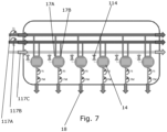
- Fig. 7 schematically illustrates water flow through a controller 6 for a water supply system 1.
- Hot water and cold water are supplied to each flow regulator 14 via a hot water inlet 17A and a cold water inlet 17B.
- a common hot water pipe 117A supplies hot water
- a common cold water supply pipe 117B supplies cold water.
- the hot and cold water is mixed to provide water at a requested temperature and flow.
- the flow regulator 14 comprises regulation elements (see also Figs. 11A and 11B ) and a step motor, as described below in relation to Figs. 10-14 .
- the controller 6 illustrated in Fig. 7 further comprise an additional valve 114 to allow supply of an additional medium to at least one water tap.
- the additional medium can be supplied to each water tap, as an additional valve 114 is provided in communication with each flow regulator 14.
- a common additional medium pipe 117C supplies the additional medium.
- the water and the additional medium are supplied to each water tap via separate outlets 18.
- separate flow meters FM and temperature sensors TS are provided at each outlet 18 to thereby provide the ability of monitoring consumption of water both with regard to flow and temperature.
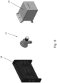
- Fig. 8 illustrates separate parts of the controller 6 illustrated in Fig. 6 in an exploded view.
- Two valves 14 can be attached to the manifold 12 and each of the valves 14 can be covered by a separate housing element 10.
- Figs. 9A-9C illustrate separate parts of the controller 6 illustrated in Fig. 6 during maintenance/repair.
- Fig. 9A illustrates replacement and/or adjustment of components of the valve 14.
- the replacement/adjustment can be performed by opening the housing element 10.
- Fig. 9B illustrates replacement of an entire control element 6' of the controller 6.
- the entire control element 6' can be removed by loosening the four screws 11 and the pipe 5.
- Fig. 9C illustrates replacement of parts of the valve 14, where the valve 14 is first removed from the controller 6 and subsequently repaired.
- Figs. 10A-10C illustrate an embodiment of a flow regulator 14 in the form of a valve.
- the flow regulator 14 comprises a valve house 14A, 14B, two regulation elements 15A, 15B (see also Figs. 11A and 11B ), and a step motor 16.
- the step motor 16 is configured for moving one of the regulations elements 15B relative to the other regulation element 15A. It should be understood that the step motor in another embodiment may be substituted by another type of motor or drive element capable of moving at least one of the regulation elements.
- the inlet to the flow regulator 14 comprises a hot water inlet 17A and a cold water inlet 17B.
- an opening ratio is adjusted to thereby adjust the flow of water and the temperature of the water leaving the flow regulator 14.
- the hot water inlet 17A and the cold water inlet 17B are located at one side of the regulation elements 15A, 15B, whereas the outlet 18 of the flow regulator 14 is located at the opposite side of the regulation elements.
- a mixing chamber 118 is formed at this opposite side of the regulation elements 15A, 15B.
- the outlet 18 is in fluid communication with the mixing chamber 118 to provide water of required flow and temperature at each water tap.
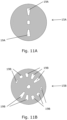
- Figs. 11A-11B illustrate an embodiment of regulation elements 15A, 15B of the flow regulator in Figs. 10A-10C .
- the regulation element 15B is the movable element, whereas the other regulation element 15A is the stationary element.
- the openings 19A in the stationary regulation element 15A are in fluid communication with the hot water inlet 17A and a cold water inlet 17B, respectively.
- the movable regulation element 15B comprises ten openings 19B. Some of the openings 19B are of different size. In the illustrated embodiment, the openings 19B are identical in pairs; i.e. the ten openings 19B are formed so that five different sizes are present.
- the flow through the flow regulator 14 is dependent on the overlap between the openings 19A in the stationary regulation element 15A and the openings 19B in the movable regulation element 15B. The overlap also determined the temperature of the flow of water.
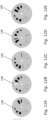
- Figs. 12A-12E illustrate the regulation element 15B of Fig. 11B in different positions. The different positions correspond to different temperature of the flow of water:
- the water flows through the flow regulator via the non-coloured openings in Figs. 12A-12E .
- the dark coloured openings and the shaded openings are openings in the movable regulation element 15B being blocked by the stationary regulation element 15A.
- Flow and water temperature can be varied by providing regulation elements of another size and/or shape, with a different number of openings, with a different size and/or shape of the openings, etc.
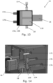
- Fig. 13 schematically illustrates a cross-section of a part of a controller 6 for a water supply system 1.
- the flow regulator 14 comprises two regulation elements 15A, 15B (see also Figs. 11A and 11B ), and a step motor 16.
- the inlet to the flow regulator 14 comprises a hot water inlet 17A and a cold water inlet 17B.
- the hot water inlet 17A and the cold water inlet 17B are located at one side of the regulation elements 15A, 15B, whereas the outlet 18 of the flow regulator 14 is located at the opposite side of the regulation elements.
- a mixing chamber 118 is formed at this opposite side.
- the outlet 18 is in fluid communication with the mixing chamber 118 to provide water of required flow and temperature at each water tap.
- An additional valve 114 is provided to allow supply of an additional medium to at least one water tap. The additional medium is provided via the additional valve 114 to the mixing chamber 118.
- the regulation elements 15A, 15B may be in closed configuration, whereby water is not allowed to flow through the openings 19A, 19B (see Fig. 11A, 11B ) in the regulation elements. Thereby it may be achieved, that the additional medium flows backwards into the hot water and cold water supply.
- Fig. 14 illustrates a cross-section of a part of a controller 6 for a water supply system 1.
- the flow regulator 14 comprises two regulation elements 15A, 15B and a step motor 16.
- the inlet to the flow regulator 14 comprises a hot water inlet 17A and a cold water inlet 17B.
- An additional medium is provided at the inlet 17C.
- the outlet 18 is in fluid communication with the mixing chamber 118 to provide water of required flow and temperature at each water tap.
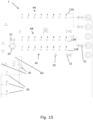
- Fig. 15 schematically illustrates an embodiment of a water supply system 1.
- the upper controller 6A comprises eight manifolds for supply of water to eight different water taps.
- the middle controller 6B comprises eight manifolds for supply of water to eight different water taps in the form of heaters, such as radiators and/or floor heaters.
- the lower controller 6C comprises eight manifolds for the return of water form eight different heaters.
- the flow directions are illustrated by the arrows 30.
- the water supply system 1 further comprises a number of check valves 32 and a pump 34.
- the water supply system further comprises three different reservoirs 36.
- the upper reservoir 36 labelled 1 is for boiling water
- the middle reservoir 36 labelled 2 is for cold water
- the lower reservoir 36 labelled 3 is for cold, sparkling water.
- the three reservoirs 36 i.e. additional supply devices each comprising an additional medium
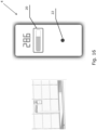
- Fig. 16 illustrates an embodiment of an operation device 4.
- the operation device 4 is mounted at the wall next to water tap 3 in the form of a washbasin.
- the water temperature is displayed, here as 28.6 degrees Celsius.
- the touch panel 20 is for registration of a touch to thereby operate the controller.
- the illustrated operation device 4 comprises a gesture sensor 22 configured for sensing a gesture of a user.
- the gesture sensor 22 may be configured to control operation based on the following gestures: An 'up' gesture may increase the flow, whereas a 'down' gesture may decrease the flow. 'Left' and 'right' gestures may increase and decrease the temperature, respectively. A gesture towards the gesture sensor 22 may turn on and/or turn off water. It should be understood, that the above gestures are meant as examples of gestures only. In an alternative embodiment, 'left' and 'right' gestures may increase and decrease the flow, respectively.
- gestures may also be applicable, such as gestures of different speed/sensitivity or such as circular gestures.
- Fig. 17A and 17B illustrate an alternative embodiment of an operation device 4.
- the operation device 4 comprises a battery 28, a proximity sensor 24, and three distance sensors 26.
- a user can choose between five levels of water flow and ten levels of water temperature. This is done by hovering the hand over the three distance sensors 26. By moving the hand up, down, and from side to side, flow and temperature are controlled.
- the proximity sensor 24 which can be touchless or an on/off button can be used to turn on and off the water tap.
- An LED 28 is integrated in the operation device 4.
- the LED 28 may be used to provide feedback to a user.
- Figs. 18A-18D illustrate an alternative embodiment of an operation device 4.
- the illustrated operation device 4 is of a size and shape which allows the operation device to be built into a fixation 40 for a traditional wall socket.
- the fixation 40 is illustrated in a front-view and from behind in Figs. 18C and 18D.
- Fig. 18A is a front view of the operation device 4, and Fig. 18B illustrated the operation device 4 inserted flush into a wall in the fixation 40.
- the illustrated operation device 4 comprises four press buttons 42 for controlling water flow and water temperature, an LED 28 to provide feedback to a user, and a sensor 24 which can be used to turn on and off the water tap.
- Figs. 19A-19C illustrate an alternative embodiment of an operation device 4.
- the illustrated operation device 4 is likewise of a size and shape which allows the operation device to be built into a fixation 40 for a traditional wall socket.
- the fixation 40 is illustrated in a front-view in Fig. 19C.
- Fig. 19A is a front view of the operation device 4, and Fig. 19B illustrated the operation device 4 inserted flush into a wall in the fixation 40.
- the illustrated operation device 4 comprises four touch sensors 44 for controlling water flow and water temperature by touching the sensors 44, and an LED 28 to provide feedback to a user.
Landscapes
- Engineering & Computer Science (AREA)
- Health & Medical Sciences (AREA)
- Water Supply & Treatment (AREA)
- Public Health (AREA)
- Hydrology & Water Resources (AREA)
- Life Sciences & Earth Sciences (AREA)
- Physics & Mathematics (AREA)
- Chemical & Material Sciences (AREA)
- General Engineering & Computer Science (AREA)
- Mechanical Engineering (AREA)
- Combustion & Propulsion (AREA)
- Thermal Sciences (AREA)
- Automation & Control Theory (AREA)
- General Physics & Mathematics (AREA)
- Fluid Mechanics (AREA)
- Domestic Plumbing Installations (AREA)
- Flow Control (AREA)
- Devices For Dispensing Beverages (AREA)
- Massaging Devices (AREA)
- Catching Or Destruction (AREA)
Claims (11)
- Wasserversorgungssystem (1), das umfasst:- eine zentrale Wasserversorgung (2),- eine Mehrzahl von Wasserhähnen (3);- eine Betriebsvorrichtung (4), die an einem Wasserhahn (3) angeordnet ist,- ein Rohrleitungssystem (5), das die zentrale Wasserversorgung (2) und die Mehrzahl von Wasserhähnen (3) verbindet, wobei das Rohrleitungssystem (5) einen getrennten Strömungsweg von der zentralen Wasserversorgung (2) zu jedem Wasserhahn (3) umfasst; und- eine Steuerung (6) zum individuellen Steuern eines Stroms von Wasser aus der zentralen Wasserversorgung (2) zu der Mehrzahl von Wasserhähnen (3) und zum individuellen Steuern einer Auslasstemperatur des Wasserstroms an einem Auslass der zentralen Wasserversorgung (2); wobei die Steuerung (6) einen Strömungsregler (14) für jeden Wasserhahn (3) umfasst, wobei der Strömungsregler (14) dazu ausgestaltet ist, sowohl den Wasserstrom als auch die Auslasstemperatur des Wasserstroms zu steuern;wobei die Steuerung (6) an der zentralen Wasserversorgung (2) angeordnet ist, und wobei die Steuerung (6) über die Betriebsvorrichtung (4) an dem Wasserhahn (3) betreibbar und dazu ausgestaltet ist, den Wasserstrom und die Auslasstemperatur auf der Grundlage einer empfangenen Bedarfsanforderung von der Betriebsvorrichtung (4) zu steuern.
- Wasserversorgungssystem (1) nach Anspruch 1, wobei die Betriebsvorrichtung (4) dazu ausgestaltet ist, ein elektrisches Bedarfsanforderungssignal zu erzeugen, und wobei die Steuerung (6) dazu ausgestaltet ist, das elektrische Bedarfsanforderungssignal zu empfangen, und dazu ausgestaltet ist, den Wasserstrom und die Auslasstemperatur als Reaktion auf das Bedarfsanforderungssignal zu steuern.
- Wasserversorgungssystem (1) nach einem der vorstehenden Ansprüche, wobei eine Betriebsvorrichtung (4) an jedem Wasserhahn (3) angeordnet ist, und wobei die Betriebsvorrichtung (4) dazu ausgestaltet ist, mit der Steuerung (6) zu kommunizieren, um den Wasserstrom zu dem Wasserhahn (3) zu steuern und die Auslasstemperatur des Wasserstroms aus der zentralen Wasserversorgung (2) zu steuern.
- Wasserversorgungssystem (1) nach einem der vorstehenden Ansprüche, wobei die Betriebsvorrichtung (4) dazu ausgestaltet ist, ein Betriebssignal in Form zumindest eines aus einem Berührungssignal, einem akustischen Signal und einem Gestiksignal zu empfangen, und dazu ausgestaltet ist, die Steuerung (6) auf der Grundlage des empfangenen Signals zu betreiben.
- Wasserversorgungssystem (1) nach einem der vorstehenden Ansprüche, das ferner eine Datenbank umfasst, wobei die Steuerung (6) mit der Datenbank in Kommunikation steht, die eine Mehrzahl von vordefinierten Steuerungsstrategien umfasst, die jeweils einen angefragten Wasserstrom und eine angefragte Temperatur definieren, und wobei die Betriebsvorrichtung (4) dazu ausgestaltet ist, zumindest eine vordefinierte Steuerstrategie auszuwählen.
- Wasserversorgungssystem (1) nach einem der vorstehenden Ansprüche, wobei das Rohrleitungssystem (5) ein Innenrohr und ein Außenrohr umfasst, die coaxial angeordnet sind, wobei das Außenrohr dazu ausgestaltet ist, das Innenrohr zu schützen.
- Wasserversorgungssystem (1) nach einem der vorstehenden Ansprüche, das ferner eine Überwachungseinheit umfasst, wobei die Steuerung (6) dazu ausgestaltet ist, ein Gebrauchssignal an die Überwachungseinheit weiterzuleiten, das den Wasserstrom von der zentralen Wasserversorgung (2) festlegt, und wobei die Überwachungseinheit dazu ausgestaltet ist, das Gebrauchssignal zu speichern.
- Wasserversorgungssystem (1) nach Anspruch 7, wobei die Steuerung (6) ferner dazu ausgestaltet ist, ein Temperatursignal an die Überwachungseinheit weiterzuleiten, das die Temperatur des Wasserstroms von der zentralen Wasserversorgung (2) festlegt, und wobei die Überwachungseinheit dazu ausgestaltet ist, das Temperatursignal zu speichern.
- Wasserversorgungssystem (1) nach einem der vorstehenden Ansprüche, das ferner eine zusätzliche Versorgungsvorrichtung umfasst, wobei die zentrale Wasserversorgung (2) mit der zusätzlichen Versorgungsvorrichtung in Fluidverbindung steht, die ein zusätzliches Medium umfasst, und wobei die Versorgung mit dem zusätzlichen Medium zu zumindest einem Wasserhahn (3) durch die Steuerung (6) gesteuert wird.
- Wasserversorgungssystem (1) nach Anspruch 9, wobei die Steuerung (6) dazu ausgestaltet ist, die Versorgung mit dem Wasserstrom und die Versorgung mit dem zusätzlichen Medium zu zumindest einem Wasserhahn (3) gleichzeitig zu steuern.
- Verfahren zum Steuern eines Wasserversorgungssystems (1) nach einem der vorstehenden Ansprüche, wobei das Verfahren einen Schritt des Betreibens der Steuerung (6) über die Betriebsvorrichtung (4) an dem Wasserhahn (3) umfasst, um den Wasserstrom und die Auslasstemperatur auf der Grundlage einer empfangenen Bedarfsanforderung von der Betriebsvorrichtung (4) zu steuern.
Priority Applications (1)
| Application Number | Priority Date | Filing Date | Title |
|---|---|---|---|
| EP25171685.8A EP4582640A3 (de) | 2020-01-31 | 2021-01-28 | Wasserversorgungssystem |
Applications Claiming Priority (3)
| Application Number | Priority Date | Filing Date | Title |
|---|---|---|---|
| EP20154796 | 2020-01-31 | ||
| EP20201133 | 2020-10-09 | ||
| PCT/EP2021/052022 WO2021152036A1 (en) | 2020-01-31 | 2021-01-28 | A water supply system |
Related Child Applications (1)
| Application Number | Title | Priority Date | Filing Date |
|---|---|---|---|
| EP25171685.8A Division EP4582640A3 (de) | 2020-01-31 | 2021-01-28 | Wasserversorgungssystem |
Publications (3)
| Publication Number | Publication Date |
|---|---|
| EP4097308A1 EP4097308A1 (de) | 2022-12-07 |
| EP4097308C0 EP4097308C0 (de) | 2025-04-23 |
| EP4097308B1 true EP4097308B1 (de) | 2025-04-23 |
Family
ID=74215974
Family Applications (2)
| Application Number | Title | Priority Date | Filing Date |
|---|---|---|---|
| EP21701543.7A Active EP4097308B1 (de) | 2020-01-31 | 2021-01-28 | Wasserversorgungssystem |
| EP25171685.8A Pending EP4582640A3 (de) | 2020-01-31 | 2021-01-28 | Wasserversorgungssystem |
Family Applications After (1)
| Application Number | Title | Priority Date | Filing Date |
|---|---|---|---|
| EP25171685.8A Pending EP4582640A3 (de) | 2020-01-31 | 2021-01-28 | Wasserversorgungssystem |
Country Status (9)
| Country | Link |
|---|---|
| US (1) | US12524028B2 (de) |
| EP (2) | EP4097308B1 (de) |
| JP (1) | JP7640565B2 (de) |
| CN (2) | CN115066530B (de) |
| AU (1) | AU2021215004B2 (de) |
| CA (1) | CA3169620A1 (de) |
| ES (1) | ES3025202T3 (de) |
| PL (1) | PL4097308T3 (de) |
| WO (1) | WO2021152036A1 (de) |
Families Citing this family (1)
| Publication number | Priority date | Publication date | Assignee | Title |
|---|---|---|---|---|
| IT202400010021A1 (it) * | 2024-05-06 | 2025-11-06 | Emanuele Gandellini | Sistema di erogazione di acqua sanitaria in locali di edifici. |
Family Cites Families (38)
| Publication number | Priority date | Publication date | Assignee | Title |
|---|---|---|---|---|
| US2991481A (en) * | 1958-03-17 | 1961-07-11 | Harold M Book | Fluid distribution control system |
| IT1133667B (it) * | 1980-10-02 | 1986-07-09 | Bonato Elettroindustria Spa | Procedimento e apparecchiatura per la distribuzione di acqua fredda o miscelata a diverse utenze |
| GB2172413B (en) | 1985-03-12 | 1988-11-02 | Caradon Mira Ltd | Water supply installation for ablutionary purposes |
| JPH01203842A (ja) | 1988-02-10 | 1989-08-16 | Toto Ltd | 自動給湯装置 |
| US4886207A (en) * | 1988-09-14 | 1989-12-12 | Lee Chang H | Automatic mixing faucet |
| US6250558B1 (en) * | 1999-08-09 | 2001-06-26 | Miguel E. Dogre Cuevas | Shower temperature and pressure control system |
| AT409574B (de) | 2000-03-01 | 2002-09-25 | Vaillant Gmbh | Warmwasseranlage |
| WO2003023155A1 (en) * | 2001-09-13 | 2003-03-20 | Paolo Andreotti | Withdrawable single-pipe sanitary system |
| JP4445884B2 (ja) | 2005-02-28 | 2010-04-07 | 株式会社ノーリツ | 給湯システム |
| CN1821637A (zh) | 2006-01-05 | 2006-08-23 | 崔荀 | 一种陶瓷阀片组件及装有该组件的冷热水混合阀 |
| IT1391761B1 (it) * | 2008-11-11 | 2012-01-27 | Fima Carlo Frattini S P A | Rubinetto elettronico |
| CN201567615U (zh) * | 2009-10-13 | 2010-09-01 | 纪勇 | 一种自动供水装置 |
| US20110088799A1 (en) * | 2009-10-15 | 2011-04-21 | Woo-Chong Jung | Digital faucet system |
| US9085880B2 (en) * | 2010-02-01 | 2015-07-21 | Kohler Co. | Systems and methods for providing a programmable shower interface |
| US9777470B2 (en) * | 2010-02-01 | 2017-10-03 | Kohler Co. | Shower control system with network features |
| CN101893114B (zh) * | 2010-07-14 | 2011-09-07 | 潘兆铿 | 一种带压力平衡装置的混合调节恒温水阀 |
| PL2557365T3 (pl) | 2011-08-09 | 2015-10-30 | Danfoss As | Układ kontrolny rozprowadzania płynu |
| US9062790B2 (en) * | 2012-08-24 | 2015-06-23 | Kohler Co. | System and method to position and retain a sensor in a faucet spout |
| CN102979135A (zh) | 2012-10-30 | 2013-03-20 | 汤红学 | 一种温泉供水系统 |
| CN103193308A (zh) * | 2013-03-29 | 2013-07-10 | 江苏新美星包装机械股份有限公司 | 一种矿物质在线添加装置 |
| KR101501051B1 (ko) * | 2013-04-29 | 2015-03-12 | 설재한 | 욕조의 스마트 수전장치 |
| DK2874039T3 (en) * | 2013-11-19 | 2017-07-17 | Grundfos Holding As | Method of controlling a heat transfer system as well as such a heat transfer system |
| CN104820380B (zh) | 2014-02-02 | 2019-09-24 | 科勒公司 | 淋浴间控制系统 |
| CN111692379B (zh) | 2014-09-16 | 2022-06-10 | 夏立军 | 一种用于处理废料的系统 |
| GB2549209B (en) * | 2014-10-29 | 2020-11-04 | Nec Corp | Tap water management system, tap water management device, tap water management method, and tap water management program recording medium |
| KR20160125117A (ko) * | 2015-04-21 | 2016-10-31 | 엘지전자 주식회사 | 스마트 수도 밸브 시스템 및 그 제어 방법 |
| WO2017046109A1 (en) * | 2015-09-18 | 2017-03-23 | Koninklijke Philips N.V. | Monitoring device for subject behavior monitoring |
| US11620553B2 (en) * | 2016-04-21 | 2023-04-04 | Utopus Insights, Inc. | System and method for forecasting leaks in a fluid-delivery pipeline network |
| CN206320407U (zh) * | 2016-12-29 | 2017-07-11 | 王建续 | 一种医用消毒水龙头 |
| CN206404603U (zh) * | 2016-12-30 | 2017-08-15 | 北京天天一泉净水设备股份有限公司 | 一种碳酸温泉生成机 |
| CN208182681U (zh) * | 2017-05-04 | 2018-12-04 | 童筑林 | 一种向可流动的饮用水中添加矿物质的装置及系统 |
| US10745893B2 (en) * | 2017-07-19 | 2020-08-18 | Google Llc | User friendly systems and devices facilitating water conservation in the smart home |
| US20200224394A1 (en) * | 2017-10-10 | 2020-07-16 | Michael Antonio Mariano | Electronic Water Distribution Center With Electronic Drain Network |
| US10514172B2 (en) | 2018-01-15 | 2019-12-24 | Advanced Conservation Technology Distribution, Inc. | Fluid distribution system |
| US11047761B1 (en) * | 2018-02-08 | 2021-06-29 | Moen Incorporated | Integrated leak detection |
| CN208075095U (zh) | 2018-04-17 | 2018-11-09 | 夏训 | 一种用于家用热水水温控制的智能家居系统 |
| ES2735648B2 (es) * | 2018-06-19 | 2020-05-20 | Sedal S L U | Dispositivo de mezcla de liquidos con control electronico de alta dinamica de regulacion y metodo de funcionamiento del mismo |
| KR102103153B1 (ko) * | 2019-02-25 | 2020-04-22 | 방만혁 | 길이 조절이 가능한 비정척 관 연결 장치 및, 그 연결 장치의 시공방법 |
-
2021
- 2021-01-28 EP EP21701543.7A patent/EP4097308B1/de active Active
- 2021-01-28 JP JP2022546692A patent/JP7640565B2/ja active Active
- 2021-01-28 CA CA3169620A patent/CA3169620A1/en active Pending
- 2021-01-28 CN CN202180011732.9A patent/CN115066530B/zh active Active
- 2021-01-28 WO PCT/EP2021/052022 patent/WO2021152036A1/en not_active Ceased
- 2021-01-28 AU AU2021215004A patent/AU2021215004B2/en active Active
- 2021-01-28 EP EP25171685.8A patent/EP4582640A3/de active Pending
- 2021-01-28 CN CN202511285351.6A patent/CN120889323A/zh active Pending
- 2021-01-28 PL PL21701543.7T patent/PL4097308T3/pl unknown
- 2021-01-28 US US17/795,314 patent/US12524028B2/en active Active
- 2021-01-28 ES ES21701543T patent/ES3025202T3/es active Active
Also Published As
| Publication number | Publication date |
|---|---|
| AU2021215004A1 (en) | 2022-09-08 |
| EP4097308C0 (de) | 2025-04-23 |
| US20230078137A1 (en) | 2023-03-16 |
| ES3025202T3 (en) | 2025-06-06 |
| AU2021215004B2 (en) | 2026-01-22 |
| EP4582640A3 (de) | 2025-10-15 |
| CA3169620A1 (en) | 2021-08-05 |
| CN120889323A (zh) | 2025-11-04 |
| EP4097308A1 (de) | 2022-12-07 |
| CN115066530B (zh) | 2025-09-26 |
| EP4582640A2 (de) | 2025-07-09 |
| US12524028B2 (en) | 2026-01-13 |
| WO2021152036A1 (en) | 2021-08-05 |
| PL4097308T3 (pl) | 2025-08-11 |
| JP7640565B2 (ja) | 2025-03-05 |
| JP2023514983A (ja) | 2023-04-12 |
| CN115066530A (zh) | 2022-09-16 |
| WO2021152036A8 (en) | 2021-09-10 |
Similar Documents
| Publication | Publication Date | Title |
|---|---|---|
| CN102460025B (zh) | 一种带改进控制部件的冷热水供应系统 | |
| CN101133373B (zh) | 对洗浴设备或关于洗浴设备的改进 | |
| US9366015B2 (en) | Method of controlling mixing valve | |
| JP2011519011A (ja) | 温度調節の容易な混合水及び冷温水供給システム | |
| US9268342B2 (en) | Water heater with integral thermal mixing valve assembly and method | |
| US20120192965A1 (en) | Water supply system with recirculation | |
| CN107709675A (zh) | 用于具有水槽下龙头基部和水槽上龙头头部的水槽下装置龙头的控制单元 | |
| CN101495932A (zh) | 自动浴缸填充器 | |
| ITPD20070271A1 (it) | Dispositivo elettronico di miscelazione e di regolazione della portata d' acqua | |
| US20110168266A1 (en) | Closed System Water Conservation Apparatus | |
| CA3059238C (en) | Automated shower water saving device | |
| GB2580659A (en) | Heated fluid control system | |
| US12524028B2 (en) | Water supply system | |
| KR100940256B1 (ko) | 서머밸브를 이용하여 다수의 수전으로 냉수 및 혼합수를 토출하는 온수보일러 및 순간온수기의 온수공급시스템 | |
| KR101542886B1 (ko) | 급탕 설비의 급탕 제어방법 | |
| JP5735311B2 (ja) | ヘッダ流量制御システム | |
| CN101258368A (zh) | 水控制器 | |
| KR101020081B1 (ko) | 냉,온수공급시스템 | |
| KR101515971B1 (ko) | 급탕 설비 | |
| DE102008053879A1 (de) | Elektrische Sanitärarmatur | |
| KR101644563B1 (ko) | 절수 배관 시스템 | |
| KR200426465Y1 (ko) | 급탕온도조절기 | |
| IT202000010210A1 (it) | Sistema di miscelazione e regolazione della portata d'acqua con elettrovalvole ed unita' di controllo e di alimentazione per impianti idraulici sanitari e di riscaldamento monotubo | |
| JP5873322B2 (ja) | ヘッダ制御システム |
Legal Events
| Date | Code | Title | Description |
|---|---|---|---|
| STAA | Information on the status of an ep patent application or granted ep patent |
Free format text: STATUS: UNKNOWN |
|
| STAA | Information on the status of an ep patent application or granted ep patent |
Free format text: STATUS: THE INTERNATIONAL PUBLICATION HAS BEEN MADE |
|
| PUAI | Public reference made under article 153(3) epc to a published international application that has entered the european phase |
Free format text: ORIGINAL CODE: 0009012 |
|
| STAA | Information on the status of an ep patent application or granted ep patent |
Free format text: STATUS: REQUEST FOR EXAMINATION WAS MADE |
|
| 17P | Request for examination filed |
Effective date: 20220831 |
|
| AK | Designated contracting states |
Kind code of ref document: A1 Designated state(s): AL AT BE BG CH CY CZ DE DK EE ES FI FR GB GR HR HU IE IS IT LI LT LU LV MC MK MT NL NO PL PT RO RS SE SI SK SM TR |
|
| DAV | Request for validation of the european patent (deleted) | ||
| DAX | Request for extension of the european patent (deleted) | ||
| STAA | Information on the status of an ep patent application or granted ep patent |
Free format text: STATUS: EXAMINATION IS IN PROGRESS |
|
| 17Q | First examination report despatched |
Effective date: 20240618 |
|
| 17Q | First examination report despatched |
Effective date: 20240626 |
|
| GRAP | Despatch of communication of intention to grant a patent |
Free format text: ORIGINAL CODE: EPIDOSNIGR1 |
|
| STAA | Information on the status of an ep patent application or granted ep patent |
Free format text: STATUS: GRANT OF PATENT IS INTENDED |
|
| INTG | Intention to grant announced |
Effective date: 20241219 |
|
| GRAS | Grant fee paid |
Free format text: ORIGINAL CODE: EPIDOSNIGR3 |
|
| GRAA | (expected) grant |
Free format text: ORIGINAL CODE: 0009210 |
|
| STAA | Information on the status of an ep patent application or granted ep patent |
Free format text: STATUS: THE PATENT HAS BEEN GRANTED |
|
| AK | Designated contracting states |
Kind code of ref document: B1 Designated state(s): AL AT BE BG CH CY CZ DE DK EE ES FI FR GB GR HR HU IE IS IT LI LT LU LV MC MK MT NL NO PL PT RO RS SE SI SK SM TR |
|
| REG | Reference to a national code |
Ref country code: GB Ref legal event code: FG4D |
|
| RIN1 | Information on inventor provided before grant (corrected) |
Inventor name: GELLERT, JIMMI |
|
| REG | Reference to a national code |
Ref country code: CH Ref legal event code: EP |
|
| REG | Reference to a national code |
Ref country code: DE Ref legal event code: R096 Ref document number: 602021029558 Country of ref document: DE |
|
| REG | Reference to a national code |
Ref country code: IE Ref legal event code: FG4D |
|
| REG | Reference to a national code |
Ref country code: ES Ref legal event code: FG2A Ref document number: 3025202 Country of ref document: ES Kind code of ref document: T3 Effective date: 20250606 |
|
| U01 | Request for unitary effect filed |
Effective date: 20250507 |
|
| U07 | Unitary effect registered |
Designated state(s): AT BE BG DE DK EE FI FR IT LT LU LV MT NL PT RO SE SI Effective date: 20250514 |
|
| PG25 | Lapsed in a contracting state [announced via postgrant information from national office to epo] |
Ref country code: GR Free format text: LAPSE BECAUSE OF FAILURE TO SUBMIT A TRANSLATION OF THE DESCRIPTION OR TO PAY THE FEE WITHIN THE PRESCRIBED TIME-LIMIT Effective date: 20250724 |
|
| PG25 | Lapsed in a contracting state [announced via postgrant information from national office to epo] |
Ref country code: HR Free format text: LAPSE BECAUSE OF FAILURE TO SUBMIT A TRANSLATION OF THE DESCRIPTION OR TO PAY THE FEE WITHIN THE PRESCRIBED TIME-LIMIT Effective date: 20250423 |
|
| PG25 | Lapsed in a contracting state [announced via postgrant information from national office to epo] |
Ref country code: RS Free format text: LAPSE BECAUSE OF FAILURE TO SUBMIT A TRANSLATION OF THE DESCRIPTION OR TO PAY THE FEE WITHIN THE PRESCRIBED TIME-LIMIT Effective date: 20250723 |
|
| PG25 | Lapsed in a contracting state [announced via postgrant information from national office to epo] |
Ref country code: IS Free format text: LAPSE BECAUSE OF FAILURE TO SUBMIT A TRANSLATION OF THE DESCRIPTION OR TO PAY THE FEE WITHIN THE PRESCRIBED TIME-LIMIT Effective date: 20250823 |
|
| PG25 | Lapsed in a contracting state [announced via postgrant information from national office to epo] |
Ref country code: SM Free format text: LAPSE BECAUSE OF FAILURE TO SUBMIT A TRANSLATION OF THE DESCRIPTION OR TO PAY THE FEE WITHIN THE PRESCRIBED TIME-LIMIT Effective date: 20250423 |
|
| PG25 | Lapsed in a contracting state [announced via postgrant information from national office to epo] |
Ref country code: CZ Free format text: LAPSE BECAUSE OF FAILURE TO SUBMIT A TRANSLATION OF THE DESCRIPTION OR TO PAY THE FEE WITHIN THE PRESCRIBED TIME-LIMIT Effective date: 20250423 |
|
| PG25 | Lapsed in a contracting state [announced via postgrant information from national office to epo] |
Ref country code: SK Free format text: LAPSE BECAUSE OF FAILURE TO SUBMIT A TRANSLATION OF THE DESCRIPTION OR TO PAY THE FEE WITHIN THE PRESCRIBED TIME-LIMIT Effective date: 20250423 |
|
| REG | Reference to a national code |
Ref country code: CH Ref legal event code: U11 Free format text: ST27 STATUS EVENT CODE: U-0-0-U10-U11 (AS PROVIDED BY THE NATIONAL OFFICE) Effective date: 20260201 |
|
| PLBE | No opposition filed within time limit |
Free format text: ORIGINAL CODE: 0009261 |
|
| STAA | Information on the status of an ep patent application or granted ep patent |
Free format text: STATUS: NO OPPOSITION FILED WITHIN TIME LIMIT |
|
| REG | Reference to a national code |
Ref country code: CH Ref legal event code: L10 Free format text: ST27 STATUS EVENT CODE: U-0-0-L10-L00 (AS PROVIDED BY THE NATIONAL OFFICE) Effective date: 20260304 |
|
| U20 | Renewal fee for the european patent with unitary effect paid |
Year of fee payment: 6 Effective date: 20260202 |
|
| 26N | No opposition filed |
Effective date: 20260126 |
|
| PGFP | Annual fee paid to national office [announced via postgrant information from national office to epo] |
Ref country code: GB Payment date: 20260121 Year of fee payment: 6 |
|
| PGFP | Annual fee paid to national office [announced via postgrant information from national office to epo] |
Ref country code: ES Payment date: 20260204 Year of fee payment: 6 |
|
| PGFP | Annual fee paid to national office [announced via postgrant information from national office to epo] |
Ref country code: NO Payment date: 20260126 Year of fee payment: 6 |
|
| PGFP | Annual fee paid to national office [announced via postgrant information from national office to epo] |
Ref country code: CH Payment date: 20260201 Year of fee payment: 6 |
|
| PGFP | Annual fee paid to national office [announced via postgrant information from national office to epo] |
Ref country code: PL Payment date: 20260102 Year of fee payment: 6 |