EP4100283B1 - Frontschutzformteil für ein kraftfahrzeug mit einer radar- und frontstruktur eines fahrzeugs mit einem solchen schutzformteil - Google Patents
Frontschutzformteil für ein kraftfahrzeug mit einer radar- und frontstruktur eines fahrzeugs mit einem solchen schutzformteil Download PDFInfo
- Publication number
- EP4100283B1 EP4100283B1 EP21701985.0A EP21701985A EP4100283B1 EP 4100283 B1 EP4100283 B1 EP 4100283B1 EP 21701985 A EP21701985 A EP 21701985A EP 4100283 B1 EP4100283 B1 EP 4100283B1
- Authority
- EP
- European Patent Office
- Prior art keywords
- protective moulding
- moulding
- protective
- impact absorbing
- vehicle
- Prior art date
- Legal status (The legal status is an assumption and is not a legal conclusion. Google has not performed a legal analysis and makes no representation as to the accuracy of the status listed.)
- Active
Links
Images



Classifications
-
- B—PERFORMING OPERATIONS; TRANSPORTING
- B60—VEHICLES IN GENERAL
- B60R—VEHICLES, VEHICLE FITTINGS, OR VEHICLE PARTS, NOT OTHERWISE PROVIDED FOR
- B60R19/00—Wheel guards; Radiator guards, e.g. grilles; Obstruction removers; Fittings damping bouncing force in collisions
- B60R19/02—Bumpers, i.e. impact receiving or absorbing members for protecting vehicles or fending off blows from other vehicles or objects
- B60R19/48—Bumpers, i.e. impact receiving or absorbing members for protecting vehicles or fending off blows from other vehicles or objects combined with, or convertible into, other devices or objects, e.g. bumpers combined with road brushes, bumpers convertible into beds
- B60R19/483—Bumpers, i.e. impact receiving or absorbing members for protecting vehicles or fending off blows from other vehicles or objects combined with, or convertible into, other devices or objects, e.g. bumpers combined with road brushes, bumpers convertible into beds with obstacle sensors of electric or electronic type
-
- B—PERFORMING OPERATIONS; TRANSPORTING
- B60—VEHICLES IN GENERAL
- B60R—VEHICLES, VEHICLE FITTINGS, OR VEHICLE PARTS, NOT OTHERWISE PROVIDED FOR
- B60R19/00—Wheel guards; Radiator guards, e.g. grilles; Obstruction removers; Fittings damping bouncing force in collisions
- B60R19/02—Bumpers, i.e. impact receiving or absorbing members for protecting vehicles or fending off blows from other vehicles or objects
- B60R19/18—Bumpers, i.e. impact receiving or absorbing members for protecting vehicles or fending off blows from other vehicles or objects characterised by the cross-section; Means within the bumper to absorb impact
- B60R2019/186—Additional energy absorbing means supported on bumber beams, e.g. cellular structures or material
-
- B—PERFORMING OPERATIONS; TRANSPORTING
- B60—VEHICLES IN GENERAL
- B60R—VEHICLES, VEHICLE FITTINGS, OR VEHICLE PARTS, NOT OTHERWISE PROVIDED FOR
- B60R19/00—Wheel guards; Radiator guards, e.g. grilles; Obstruction removers; Fittings damping bouncing force in collisions
- B60R19/02—Bumpers, i.e. impact receiving or absorbing members for protecting vehicles or fending off blows from other vehicles or objects
- B60R19/18—Bumpers, i.e. impact receiving or absorbing members for protecting vehicles or fending off blows from other vehicles or objects characterised by the cross-section; Means within the bumper to absorb impact
- B60R2019/1886—Bumper fascias and fastening means therefor
Definitions
- the subject of the invention is a front shield of a motor vehicle equipped with a radar as well as a front structure of a vehicle comprising such a shield.
- AEBS radar Advanced Energy Braking System
- ECE42 European regulation ECE42
- this radar can be found in front of the rigid impactor launched at 4km/h provided for in the ECE42 regulations in the case of these small front impacts, in particular when this impactor is positioned in front of the center of the vehicle following the width of this last.
- the invention proposes a front shield of a motor vehicle with the characteristics of claim 1.
- the radar support is located partly in front of the shock absorber in the longitudinal direction and partly below the latter vertically.
- the shock absorber element has two shock absorption stops located on either side of the radar support in the transverse direction, these stops being integral with a lower face of the shock absorber element. shock. This lower face is particularly directed towards the ground when the shield is mounted on the vehicle. It can be parallel or substantially parallel to the transverse and longitudinal directions.
- the shock absorption stops will receive and absorb a front shock on either side of the radar support. Furthermore, the radar support being located in front and then below the shock absorbing element, and in particular at least partly between the stops, a deformation of these elements during a longitudinal front impact will not cause contact between the stops. and radar support, which helps preserve radar support.
- the stops can be arranged symmetrically on either side of the radar support, the latter being located in the center of the shield in the transverse direction.
- the invention also relates to a front structure of a motor vehicle comprising a front shield according to the invention and a front cross member for supporting the shield, the shock absorbing element extending along the front cross member, facing it following a longitudinal direction of the vehicle when the front structure is mounted on the vehicle.
- This arrangement makes it possible to prevent the stops from pivoting relative to the front crossmember during a frontal impact.
- this can be obtained by a position of the stops projecting relative to the shock absorbing element at least in the longitudinal direction of the vehicle, possibly also in the vertical direction of the vehicle, towards the rear of the vehicle and the ground respectively.
- the invention finally relates to a motor vehicle comprising a shield according to the invention or a front structure according to the invention.
- front, rear, upper, lower refer to the front and rear, upper and lower directions of the vehicle, when the front structure and the front shield are mounted on the vehicle.
- the X, Y, Z axes correspond respectively to the longitudinal (front to back), transverse and vertical axis of the vehicle, the latter resting on the ground.
- the vertical direction thus corresponds to the direction of gravity.
- substantially horizontal, longitudinal or vertical we mean an element of which one or more parts defining a direction or a plane form an angle of at most ⁇ 20°, or even at most 10° or at most 5°, with a horizontal, longitudinal or vertical direction/plane.
- substantially parallel or perpendicular we mean an element of which one or more parts defining a direction or a plane forming an angle deviating by at most ⁇ 20°, or even by at most 10° or by at most 5° d 'a direction or a plane parallel or perpendicular.
- FIG. 1 represents a front shield 10 seen from its internal face 10a, the front shield 10 also having an external face 10b visible from outside the vehicle.
- the front shield 10 comprises a shield skin 12, a shock absorber element 14 extending in the transverse direction Y and fixed to the shield skin 12 on the side of the internal face 10a of the shield and a radar support 16 located at the 'front and extending below the shock absorber element 14 and fixed to the internal face 10a of the shield.
- the radar support 16 supports a radar 18, for example an AEBS radar.
- the radar support 16 is here located at the center or near the center of the shield in the transverse direction Y.
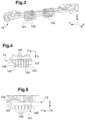
- the shock absorber element 14 has two shock absorption stops 141, 142 located on either side of the radar support 16 in the transverse direction. These stops, otherwise called “stoppers” are integral with a lower face 143 of the shock absorber element, located on the side of the radar support. This lower face 143 extends substantially in the plane of the X and Y directions of the vehicle. In other words, the stops 141, 142 project from the shock absorber element 14 vertically towards the ground.
- the stops can be arranged symmetrically on either side of the radar support 16, for better distribution of shock absorption.
- the stops could advantageously be arranged as close as possible to the radar support in the transverse direction, without however there being a Y-shaped overlap between the stops and the radar support in order to prevent the stops from coming into contact with the radar support during an X-shaped impact.
- each stop 141, 142 projects from a vertical face 144 of the shock absorber element 14 located on a side opposite the shield skin, in other words, this vertical face 144 is directed towards the rear of the vehicle ( see figure 8 ).
- Each stop can thus protrude from the shock absorbing element 14 by a predetermined distance in the longitudinal direction towards the rear of the vehicle. This allows in particular cooperation of each stop with an extreme front crosspiece as described below.
- the shock absorber element 14 can advantageously be made of polymer material, in particular the polymer materials usually used to produce shock absorption elements.
- each stop 141, 142 is made in one piece with the shock absorber element 14, for example by molding a polymer material.
- each stop 141, 142 comprises walls 145 defining ribs extending vertically and perpendicular to the transverse direction and walls 146, 147 defining a housing receiving the ribs and secured to vertical or substantially vertical edges of the ribs.
- Wall 147 is here an extension of a wall of the shock absorber element. The walls 146, 147 thus completely surround the ribs in the example, over at least part of their height (for the wall 147) or over their entire height (for the wall 146), this height being measured vertically.
- These walls 146, 147 here form a housing of generally trapezoidal shape. The invention is however not limited to this shape and a box in the shape of a parallelepiped or the like is possible.
- the housing is open on the side of a lower face opposite the shock absorber element, in other words towards the ground, thus facilitating the production of each of the stops by molding (see Figure 7 ).
- the invention is however not limited to a number of ribs, to the dimensions of the stops, nor to their shape, provided that they allow shock absorption on either side of the radar support.
- the dimensions, shapes and numbers of ribs can be determined by those skilled in the art through simulations for optimal absorption of an X-shaped shock.
- the front shield 10 has a lower part formed by the shield skin 12 and an upper part 13 forming a reinforcement, as visible more clearly figure 2 .
- the shock absorber element 14 is fixed to the shield skin 12, near the upper part 13.
- the radar support 16 is fixed to the lower part 12 and to the part upper 13 of the shield. The invention is, however, not limited to a particular number of parts of the shield.
- the radar support 14 can have at least one upper fixing element 162 and at least one lower fixing element, two, 163, 164, in the example shown.
- the at least one upper fixing element 162 is fixed to the lower part 12 and to the upper part 13 of the shield and the lower fixing elements 163, 164 are fixed only to the lower part 12. This can make it possible to improve the rigidity of the fixings, particularly at the junction of the lower and upper parts of the shield, which is located in an area generally most forward of the shield in X and therefore more deformed in the event of shock.
- the at least one upper fixing element 62 is fixed to the shield skin above the shock absorber element and the at least one lower fixing element is fixed to the bottom of the absorber element of choc.
- the shock absorber element thus extends partly in front of the shock absorber element in X.
- the shock absorber element may present, facing the radar support in the longitudinal direction, a face flat or substantially flat (face perpendicular or substantially perpendicular to the longitudinal direction) and/or a reduced dimension in X. This can further limit the risks of damage to the radar support during an impact.
- the upper fixing element 162 here forms a pierced plate for its attachment to the shield skin 12 and to the upper part 13.
- the lower fixing elements 163, 164 form vertical or substantially vertical pierced lugs, located substantially in the extension of a frame 161 for receiving and fixing the radar 18.
- the latter is here located between the upper 162 and lower fixing elements 163, 164 (see figure 2 ).
- the use of a support having a receiving and fixing part in the form of a frame makes it possible to produce a support having a certain flexibility, which favors its plastic deformation during a small impact and its return to place after the impact. It is however possible to envisage a receiving and fixing part in the form of a plate or the like, although this is not preferred.
- the radar support is made of polymer material, for example ethylene/propylene copolymer, optionally loaded with talc or the like for greater plasticity.
- each lower part 12 and upper 13 of the shield finally has openings 12a, 13a and 13b respectively (see figure 2 ) receiving visible grids 12b, 12c, 13b and 13c figure 1 .
- the presence of grilles is usual and the invention will not be limited by the number and arrangement of the openings and grilles.
- the shield skin 12 and the upper part of the shield 13 are also made of polymer material.
- the front shield 10 described is part of a front structure 20 of a motor vehicle shown figures 7 And 8 .
- This front structure 20 has a front crossmember 22 extending in the transverse direction of the vehicle.
- This front cross member 22 usually forms an extreme front cross member of the vehicle.
- the shock absorber element 14 extends along the front crossmember 22, on the front side thereof and facing the front crossmember 22 in the longitudinal direction X of the vehicle.
- the shock absorbing element 14 is located in the immediate vicinity of the front cross member 22 in -this, which prevents it from moving back further. From then on, the shock absorber element 14 as well as the stops 141, 142 will deform and absorb the shock. The presence of the stops makes it possible to limit the deformation of the elements located between them, here the radar support.
- each stop 141, 142 has an overlap distance D1 in X with the front crosspiece 22 and each stop has an overlap distance D2 in Z with the front crosspiece 22 ( fig. 8 ).
- This particular arrangement makes it possible to avoid rotation of the stops relative to the front crosspiece 22 in the event of an impact, in particular when the lower face 143 of the shock absorbing element 14 (from which the stops project) is located opposite the the crosspiece 22 in the longitudinal direction X, as shown figure 8 .
- the absence of pivoting of the stops will improve the absorption of shock by the stops in the X direction, for better protection of the radar support.
- D1 and D2 overlaps of 10 mm or more are sufficient to prevent the stops from pivoting in the event of a slight impact.
- each stop 141, 142 it would then be sufficient for each stop 141, 142 to be located opposite the front crosspiece 22 over at least part of its length measured in the longitudinal direction X to avoid pivoting of the stops in the event of an impact.
- the important thing to avoid the pivoting of the stops is in fact that in cross section, the stops 141, 142 and the shock absorbing element define an L shape such as that of the figure 8 , this L shape being opposite a corner of the front crosspiece 22.
- a D1 X overlap of 10 mm or more is sufficient to prevent rotation of the stops and improve the shock absorption behavior of the X stops.
- THE figures 6 and 7 show the deformation of the shield resulting from the maximum intrusion of an impactor 30 complying with ECE42 regulations.
- the stops 141, 142 are partly crushed against the front crosspiece 22 without having pivoted.
- the radar support 16 is inclined but intact despite the deformation of the lower part of the shield thanks to the damping provided by the stops.
- the invention thus makes it possible to obtain in a simple manner effective protection of a radar support during a weak X-ray shock.
Landscapes
- Engineering & Computer Science (AREA)
- Mechanical Engineering (AREA)
- Vibration Dampers (AREA)
- Radar Systems Or Details Thereof (AREA)
- Body Structure For Vehicles (AREA)
Claims (9)
- Frontstoßfänger (10) für ein Kraftfahrzeug, aufweisend eine Innenseite (10a) und eine Außenseite (10b) und Quer-, Längs- und vertikale Richtungen, die den jeweiligen Quer-, Längs- und vertikalen Richtungen eines Fahrzeugs entsprechen, wenn der Stoßfänger an diesem montiert ist, wobei der Stoßfänger umfasst:- eine Stoßfängerhaut (12),- ein Stoßabsorberelement (14), das sich entlang der Querrichtung erstreckt und an der Stoßfängerhaut (12) auf der Seite der Innenseite (10a) des Stoßfängers befestigt ist,- eine Radarhalterung (16), die an der Front gelegen ist und sich unter dem Stoßabsorberelement (14) erstreckt, wenn der Stoßfänger an dem Fahrzeug montiert ist, und an der Innenseite des Stoßfängers befestigt ist, wobei die Radarhalterung insbesondere in der Mitte oder in der Nähe der Mitte des Stoßfängers entlang der Querrichtung gelegen ist,
wobei das Stoßabsorberelement (14) zwei Anschläge (141, 142) zur Stoßabsorption aufweist, die beidseits der Radarhalterung (16) entlang der Querrichtung gelegen sind, wobei diese Anschläge mit einer Unterseite (143) des Stoßabsorberelements fest verbunden sind, dadurch gekennzeichnet, dass der Stoßfänger einen unteren Teil (12), der durch die Stoßfängerhaut gebildet wird, und einen oberen Teil (13), der eine Aussteifung bildet, aufweist, wobei das Stoßabsorberelement (14) an der Stoßfängerhaut in der Nähe des oberen Teils (13) befestigt ist und wobei die Radarhalterung (14) an dem unteren Teil und optional an dem oberen Teil des Stoßfängers befestigt ist. - Frontstoßfänger (10) nach Anspruch 1, dadurch gekennzeichnet, dass die Anschläge (141, 142) von einer vertikalen Seite (144) des Stoßabsorberelements vorspringen, die auf einer zur Stoßfängerhaut entgegengesetzten Seite gelegen ist.
- Frontstoßfänger (10) nach Anspruch 1 oder 2, dadurch gekennzeichnet, dass die Anschläge (141, 142) einstückig mit dem Stoßabsorberelement (14) ausgeführt sind.
- Frontstoßfänger (10) nach einem der Ansprüche 1 bis 3, dadurch gekennzeichnet, dass jeder Anschlag (141, 142) Wände (145) umfasst, die Rippen definieren, die sich vertikal und senkrecht zu der Querrichtung erstrecken, und Wände (146, 147), die ein Gehäuse definieren, das die Rippen aufnimmt und mit vertikalen oder im Wesentlichen vertikalen Rändern der Rippen fest verbunden sind, wobei das Gehäuse optional an einer unteren Seite, die zu dem Stoßabsorberelement entgegengesetzt ist, offen ist.
- Frontstoßfänger (10) nach einem der Ansprüche 1 bis 4, dadurch gekennzeichnet, dass die Radarhalterung mindestens ein oberes Befestigungselement (162) und mindestens ein unteres Befestigungselement (163, 164) umfasst, die jeweils an der Stoßfängerhaut (12) befestigt sind, wobei das mindestens eine obere Befestigungselement (162) optional auch an einem oberen Teil des Stoßfängers befestigt ist, wobei die Radarhalterung optional einen Rahmen (161) zur Aufnahme und Befestigung des Radars umfasst, der zwischen den oberen und unteren Befestigungselementen gelegen ist.
- Frontstoßfänger (10) nach einem der Ansprüche 1 bis 5, dadurch gekennzeichnet, dass das Stoßabsorberelement (14), die Radarhalterung (16) und optional der obere Teil des Stoßfängers aus Polymermaterial sind.
- Frontstruktur (20) für ein Kraftfahrzeug, dadurch gekennzeichnet, dass sie einen Frontstoßfänger (10) nach einem der Ansprüche 1 bis 6 und einen Frontquerträger (22) zur Halterung des Stoßfängers umfasst, wobei sich das Stoßabsorberelement entlang des Frontquerträgers erstreckt, gegenüber von diesem entlang einer Längsrichtung des Fahrzeugs, wenn die Frontstruktur an dem Fahrzeug montiert ist.
- Frontstruktur (20) für ein Kraftfahrzeug nach Anspruch 7, dadurch gekennzeichnet, dass jeder Anschlag (141, 142) gelegen ist:- gegenüber dem Frontquerträger (22) über mindestens einen Teil seiner entlang der Längsrichtung gemessenen Länge,- optional gegenüber dem Frontquerträger über mindestens einen Teil seiner vertikal gemessenen Höhe, wenn die Frontstruktur an dem Fahrzeug montiert ist.
- Kraftfahrzeug mit einem Stoßfänger nach einem der Ansprüche 1 bis 6 oder einer Frontstruktur nach Anspruch 7 oder 8.
Applications Claiming Priority (2)
| Application Number | Priority Date | Filing Date | Title |
|---|---|---|---|
| FR2001027A FR3106806B1 (fr) | 2020-02-03 | 2020-02-03 | Bouclier avant de véhicule automobile équipé d’un radar et structure avant de véhicule comprenant un tel bouclier |
| PCT/EP2021/051633 WO2021156090A1 (fr) | 2020-02-03 | 2021-01-25 | Bouclier avant de véhicule automobile équipé d'un radar et structure avant de véhicule comprenant un tel bouclier |
Publications (2)
| Publication Number | Publication Date |
|---|---|
| EP4100283A1 EP4100283A1 (de) | 2022-12-14 |
| EP4100283B1 true EP4100283B1 (de) | 2024-08-07 |
Family
ID=69903685
Family Applications (1)
| Application Number | Title | Priority Date | Filing Date |
|---|---|---|---|
| EP21701985.0A Active EP4100283B1 (de) | 2020-02-03 | 2021-01-25 | Frontschutzformteil für ein kraftfahrzeug mit einer radar- und frontstruktur eines fahrzeugs mit einem solchen schutzformteil |
Country Status (5)
| Country | Link |
|---|---|
| EP (1) | EP4100283B1 (de) |
| JP (1) | JP7688647B2 (de) |
| CN (1) | CN115038617B (de) |
| FR (1) | FR3106806B1 (de) |
| WO (1) | WO2021156090A1 (de) |
Families Citing this family (2)
| Publication number | Priority date | Publication date | Assignee | Title |
|---|---|---|---|---|
| FR3119811B1 (fr) * | 2021-02-17 | 2022-12-30 | Renault Sas | Ensemble comprenant un support de radar, un radôme et un bouclier d’un véhicule automobile |
| FR3148956B1 (fr) | 2023-05-25 | 2025-04-11 | Psa Automobiles Sa | Grille de pare-chocs avant de véhicule automobile avec radar frontal |
Family Cites Families (9)
| Publication number | Priority date | Publication date | Assignee | Title |
|---|---|---|---|---|
| US6634702B1 (en) * | 1999-06-23 | 2003-10-21 | Dynamit Nobel Kunstsoff Gmbh | Front-end module for a motor vehicle |
| DE102005037151A1 (de) | 2005-08-06 | 2007-02-08 | Daimlerchrysler Ag | Stoßfängeranordnung für ein Kraftfahrzeug |
| FR2904956B1 (fr) * | 2006-08-17 | 2009-04-10 | Peugeot Citroen Automobiles Sa | Pare-chocs de vehicule automobile comprenant un capteur et une entretoise formant raidisseur |
| DE102007045001A1 (de) * | 2007-09-20 | 2009-04-02 | Daimler Ag | Anordnung einer Halterung an einem Stoßfänger eines Personenkraftwagens |
| FR2935938B1 (fr) * | 2008-09-18 | 2012-02-03 | Peugeot Citroen Automobiles Sa | Piece de renfort et vehicule comportant une telle piece |
| JP6805942B2 (ja) | 2017-04-06 | 2020-12-23 | トヨタ自動車株式会社 | 車両前部構造 |
| FR3070648A1 (fr) * | 2017-09-04 | 2019-03-08 | Compagnie Plastic Omnium | Piece de structure pour vehicule |
| DE102018004377B4 (de) * | 2018-06-01 | 2025-08-14 | Stellantis Auto Sas | Kraftfahrzeug-Stoßfänger mit Sensor |
| FR3083751B1 (fr) * | 2018-07-10 | 2020-06-12 | Renault S.A.S | Guide d'air en materiau polymere expanse equipe d'elements de maintien sur une traverse extreme avant |
-
2020
- 2020-02-03 FR FR2001027A patent/FR3106806B1/fr active Active
-
2021
- 2021-01-25 WO PCT/EP2021/051633 patent/WO2021156090A1/fr not_active Ceased
- 2021-01-25 JP JP2022544408A patent/JP7688647B2/ja active Active
- 2021-01-25 EP EP21701985.0A patent/EP4100283B1/de active Active
- 2021-01-25 CN CN202180011760.0A patent/CN115038617B/zh active Active
Also Published As
| Publication number | Publication date |
|---|---|
| FR3106806B1 (fr) | 2022-01-07 |
| JP2023511921A (ja) | 2023-03-23 |
| EP4100283A1 (de) | 2022-12-14 |
| WO2021156090A1 (fr) | 2021-08-12 |
| CN115038617B (zh) | 2025-08-12 |
| FR3106806A1 (fr) | 2021-08-06 |
| JP7688647B2 (ja) | 2025-06-04 |
| CN115038617A (zh) | 2022-09-09 |
Similar Documents
| Publication | Publication Date | Title |
|---|---|---|
| EP2135775B1 (de) | Stoßstangenanordnung und entsprechendes Kraftfahrzeug | |
| EP4294679B1 (de) | Anordnung mit einem radarträger, einem radom und einer abschirmung eines kraftfahrzeugs | |
| FR2931417A1 (fr) | Dispositif d'absorption de choc et face avant comportant un tel dispositif | |
| EP3817937B1 (de) | Anordnung eines karosserieunterbaus eines fahrzeugs mit integrierter batterieanordnung und fahrzeug mit einer solchen anordnung | |
| EP3100916B1 (de) | Stossabsorbierende vorrichtung für front- und heckstruktur eines fahrzeugs, und mit dieser vorrichtung ausgestattetes fahrzeug | |
| EP4100283B1 (de) | Frontschutzformteil für ein kraftfahrzeug mit einer radar- und frontstruktur eines fahrzeugs mit einem solchen schutzformteil | |
| EP3765337B1 (de) | Vorrichtung zur befestigung eines sensors an einem fahrzeug sowie montageverfahren | |
| EP1314614A2 (de) | Stossfängeranordnung für Kraftfahrzeuge | |
| EP2135778B1 (de) | Hintere Stoßstange für Nutzfahrzeug | |
| EP4426590B1 (de) | Strukturelle unteranordnung eines stossfängers mit einer stossfängerverstärkung und zwei seitlichen montagekonsolen | |
| EP4263295B1 (de) | Stossfängervorrichtung mit integriertem absorber und fahrzeug mit dieser vorrichtung | |
| EP3820743A1 (de) | Aus einem stück expandiertem polymermaterial mit stossabsorbierenden zonen hergestellte luftführung für ein kraftfahrzeug | |
| FR3153784A1 (fr) | Absorbeur pour système de pare-chocs arrière de véhicule automobile | |
| WO2024105321A1 (fr) | Sous-ensemble de pare-chocs avant pour véhicule automobile | |
| FR3099907A1 (fr) | Déflecteur aérodynamique arrière pour véhicule automobile | |
| EP2165890B1 (de) | Verstärkungsstück und Fahrzeug mit einem solchen Stück | |
| FR3123852A1 (fr) | Ensemble pour véhicule automobile comprenant une poutre de pare-chocs et deux absorbeurs. | |
| EP2142401B1 (de) | Stossfängerquerträger und energieabsorber anordnung | |
| EP4301629B1 (de) | Stossfängerverstärkungsschnittstellenhalterung für ein kraftfahrzeug | |
| EP3350064B1 (de) | Tragstruktur für ein frontendmodul eines kraftfahrzeugs und frontendmodul mit der trägerstruktur | |
| EP2108570B1 (de) | Frontteil eines Fahrzeugs, das mit einer Halterung für einen abgeschrägten Kühlergrill ausgestattet ist | |
| FR3081423A1 (fr) | Vehicule avec dispositif d’absorption a surface d’impact augmentant durant un choc. | |
| FR3070147B1 (fr) | Dispositif de fixation d’un equipement sur un chassis de vehicule automobile ayant une cinematique de choc en rotation | |
| FR3072070B1 (fr) | Partie arriere d’un vehicule adaptee pour amortir un choc arriere qui comporte un puits dans lequel est positionnee une roue de secours | |
| FR3154064A1 (fr) | Déflecteur aéraulique pour véhicule automobile |
Legal Events
| Date | Code | Title | Description |
|---|---|---|---|
| STAA | Information on the status of an ep patent application or granted ep patent |
Free format text: STATUS: UNKNOWN |
|
| STAA | Information on the status of an ep patent application or granted ep patent |
Free format text: STATUS: THE INTERNATIONAL PUBLICATION HAS BEEN MADE |
|
| PUAI | Public reference made under article 153(3) epc to a published international application that has entered the european phase |
Free format text: ORIGINAL CODE: 0009012 |
|
| STAA | Information on the status of an ep patent application or granted ep patent |
Free format text: STATUS: REQUEST FOR EXAMINATION WAS MADE |
|
| 17P | Request for examination filed |
Effective date: 20220801 |
|
| AK | Designated contracting states |
Kind code of ref document: A1 Designated state(s): AL AT BE BG CH CY CZ DE DK EE ES FI FR GB GR HR HU IE IS IT LI LT LU LV MC MK MT NL NO PL PT RO RS SE SI SK SM TR |
|
| DAV | Request for validation of the european patent (deleted) | ||
| DAX | Request for extension of the european patent (deleted) | ||
| STAA | Information on the status of an ep patent application or granted ep patent |
Free format text: STATUS: EXAMINATION IS IN PROGRESS |
|
| 17Q | First examination report despatched |
Effective date: 20230525 |
|
| P01 | Opt-out of the competence of the unified patent court (upc) registered |
Effective date: 20230608 |
|
| GRAP | Despatch of communication of intention to grant a patent |
Free format text: ORIGINAL CODE: EPIDOSNIGR1 |
|
| STAA | Information on the status of an ep patent application or granted ep patent |
Free format text: STATUS: GRANT OF PATENT IS INTENDED |
|
| INTG | Intention to grant announced |
Effective date: 20240304 |
|
| GRAS | Grant fee paid |
Free format text: ORIGINAL CODE: EPIDOSNIGR3 |
|
| GRAA | (expected) grant |
Free format text: ORIGINAL CODE: 0009210 |
|
| STAA | Information on the status of an ep patent application or granted ep patent |
Free format text: STATUS: THE PATENT HAS BEEN GRANTED |
|
| AK | Designated contracting states |
Kind code of ref document: B1 Designated state(s): AL AT BE BG CH CY CZ DE DK EE ES FI FR GB GR HR HU IE IS IT LI LT LU LV MC MK MT NL NO PL PT RO RS SE SI SK SM TR |
|
| REG | Reference to a national code |
Ref country code: GB Ref legal event code: FG4D Free format text: NOT ENGLISH |
|
| REG | Reference to a national code |
Ref country code: CH Ref legal event code: EP |
|
| REG | Reference to a national code |
Ref country code: IE Ref legal event code: FG4D Free format text: LANGUAGE OF EP DOCUMENT: FRENCH |
|
| REG | Reference to a national code |
Ref country code: DE Ref legal event code: R096 Ref document number: 602021016798 Country of ref document: DE |
|
| REG | Reference to a national code |
Ref country code: LT Ref legal event code: MG9D |
|
| REG | Reference to a national code |
Ref country code: NL Ref legal event code: MP Effective date: 20240807 |
|
| PG25 | Lapsed in a contracting state [announced via postgrant information from national office to epo] |
Ref country code: NO Free format text: LAPSE BECAUSE OF FAILURE TO SUBMIT A TRANSLATION OF THE DESCRIPTION OR TO PAY THE FEE WITHIN THE PRESCRIBED TIME-LIMIT Effective date: 20241107 |
|
| REG | Reference to a national code |
Ref country code: AT Ref legal event code: MK05 Ref document number: 1710584 Country of ref document: AT Kind code of ref document: T Effective date: 20240807 |
|
| PG25 | Lapsed in a contracting state [announced via postgrant information from national office to epo] |
Ref country code: PT Free format text: LAPSE BECAUSE OF FAILURE TO SUBMIT A TRANSLATION OF THE DESCRIPTION OR TO PAY THE FEE WITHIN THE PRESCRIBED TIME-LIMIT Effective date: 20241209 Ref country code: NL Free format text: LAPSE BECAUSE OF FAILURE TO SUBMIT A TRANSLATION OF THE DESCRIPTION OR TO PAY THE FEE WITHIN THE PRESCRIBED TIME-LIMIT Effective date: 20240807 Ref country code: FI Free format text: LAPSE BECAUSE OF FAILURE TO SUBMIT A TRANSLATION OF THE DESCRIPTION OR TO PAY THE FEE WITHIN THE PRESCRIBED TIME-LIMIT Effective date: 20240807 Ref country code: GR Free format text: LAPSE BECAUSE OF FAILURE TO SUBMIT A TRANSLATION OF THE DESCRIPTION OR TO PAY THE FEE WITHIN THE PRESCRIBED TIME-LIMIT Effective date: 20241108 Ref country code: PL Free format text: LAPSE BECAUSE OF FAILURE TO SUBMIT A TRANSLATION OF THE DESCRIPTION OR TO PAY THE FEE WITHIN THE PRESCRIBED TIME-LIMIT Effective date: 20240807 |
|
| PG25 | Lapsed in a contracting state [announced via postgrant information from national office to epo] |
Ref country code: BG Free format text: LAPSE BECAUSE OF FAILURE TO SUBMIT A TRANSLATION OF THE DESCRIPTION OR TO PAY THE FEE WITHIN THE PRESCRIBED TIME-LIMIT Effective date: 20240807 |
|
| PG25 | Lapsed in a contracting state [announced via postgrant information from national office to epo] |
Ref country code: LV Free format text: LAPSE BECAUSE OF FAILURE TO SUBMIT A TRANSLATION OF THE DESCRIPTION OR TO PAY THE FEE WITHIN THE PRESCRIBED TIME-LIMIT Effective date: 20240807 |
|
| PG25 | Lapsed in a contracting state [announced via postgrant information from national office to epo] |
Ref country code: IS Free format text: LAPSE BECAUSE OF FAILURE TO SUBMIT A TRANSLATION OF THE DESCRIPTION OR TO PAY THE FEE WITHIN THE PRESCRIBED TIME-LIMIT Effective date: 20241207 Ref country code: AT Free format text: LAPSE BECAUSE OF FAILURE TO SUBMIT A TRANSLATION OF THE DESCRIPTION OR TO PAY THE FEE WITHIN THE PRESCRIBED TIME-LIMIT Effective date: 20240807 |
|
| PG25 | Lapsed in a contracting state [announced via postgrant information from national office to epo] |
Ref country code: HR Free format text: LAPSE BECAUSE OF FAILURE TO SUBMIT A TRANSLATION OF THE DESCRIPTION OR TO PAY THE FEE WITHIN THE PRESCRIBED TIME-LIMIT Effective date: 20240807 |
|
| PG25 | Lapsed in a contracting state [announced via postgrant information from national office to epo] |
Ref country code: RS Free format text: LAPSE BECAUSE OF FAILURE TO SUBMIT A TRANSLATION OF THE DESCRIPTION OR TO PAY THE FEE WITHIN THE PRESCRIBED TIME-LIMIT Effective date: 20241107 Ref country code: ES Free format text: LAPSE BECAUSE OF FAILURE TO SUBMIT A TRANSLATION OF THE DESCRIPTION OR TO PAY THE FEE WITHIN THE PRESCRIBED TIME-LIMIT Effective date: 20240807 |
|
| PG25 | Lapsed in a contracting state [announced via postgrant information from national office to epo] |
Ref country code: RS Free format text: LAPSE BECAUSE OF FAILURE TO SUBMIT A TRANSLATION OF THE DESCRIPTION OR TO PAY THE FEE WITHIN THE PRESCRIBED TIME-LIMIT Effective date: 20241107 Ref country code: PT Free format text: LAPSE BECAUSE OF FAILURE TO SUBMIT A TRANSLATION OF THE DESCRIPTION OR TO PAY THE FEE WITHIN THE PRESCRIBED TIME-LIMIT Effective date: 20241209 Ref country code: PL Free format text: LAPSE BECAUSE OF FAILURE TO SUBMIT A TRANSLATION OF THE DESCRIPTION OR TO PAY THE FEE WITHIN THE PRESCRIBED TIME-LIMIT Effective date: 20240807 Ref country code: NO Free format text: LAPSE BECAUSE OF FAILURE TO SUBMIT A TRANSLATION OF THE DESCRIPTION OR TO PAY THE FEE WITHIN THE PRESCRIBED TIME-LIMIT Effective date: 20241107 Ref country code: NL Free format text: LAPSE BECAUSE OF FAILURE TO SUBMIT A TRANSLATION OF THE DESCRIPTION OR TO PAY THE FEE WITHIN THE PRESCRIBED TIME-LIMIT Effective date: 20240807 Ref country code: LV Free format text: LAPSE BECAUSE OF FAILURE TO SUBMIT A TRANSLATION OF THE DESCRIPTION OR TO PAY THE FEE WITHIN THE PRESCRIBED TIME-LIMIT Effective date: 20240807 Ref country code: IS Free format text: LAPSE BECAUSE OF FAILURE TO SUBMIT A TRANSLATION OF THE DESCRIPTION OR TO PAY THE FEE WITHIN THE PRESCRIBED TIME-LIMIT Effective date: 20241207 Ref country code: HR Free format text: LAPSE BECAUSE OF FAILURE TO SUBMIT A TRANSLATION OF THE DESCRIPTION OR TO PAY THE FEE WITHIN THE PRESCRIBED TIME-LIMIT Effective date: 20240807 Ref country code: GR Free format text: LAPSE BECAUSE OF FAILURE TO SUBMIT A TRANSLATION OF THE DESCRIPTION OR TO PAY THE FEE WITHIN THE PRESCRIBED TIME-LIMIT Effective date: 20241108 Ref country code: FI Free format text: LAPSE BECAUSE OF FAILURE TO SUBMIT A TRANSLATION OF THE DESCRIPTION OR TO PAY THE FEE WITHIN THE PRESCRIBED TIME-LIMIT Effective date: 20240807 Ref country code: ES Free format text: LAPSE BECAUSE OF FAILURE TO SUBMIT A TRANSLATION OF THE DESCRIPTION OR TO PAY THE FEE WITHIN THE PRESCRIBED TIME-LIMIT Effective date: 20240807 Ref country code: BG Free format text: LAPSE BECAUSE OF FAILURE TO SUBMIT A TRANSLATION OF THE DESCRIPTION OR TO PAY THE FEE WITHIN THE PRESCRIBED TIME-LIMIT Effective date: 20240807 Ref country code: AT Free format text: LAPSE BECAUSE OF FAILURE TO SUBMIT A TRANSLATION OF THE DESCRIPTION OR TO PAY THE FEE WITHIN THE PRESCRIBED TIME-LIMIT Effective date: 20240807 |
|
| PG25 | Lapsed in a contracting state [announced via postgrant information from national office to epo] |
Ref country code: DK Free format text: LAPSE BECAUSE OF FAILURE TO SUBMIT A TRANSLATION OF THE DESCRIPTION OR TO PAY THE FEE WITHIN THE PRESCRIBED TIME-LIMIT Effective date: 20240807 Ref country code: SM Free format text: LAPSE BECAUSE OF FAILURE TO SUBMIT A TRANSLATION OF THE DESCRIPTION OR TO PAY THE FEE WITHIN THE PRESCRIBED TIME-LIMIT Effective date: 20240807 |
|
| PG25 | Lapsed in a contracting state [announced via postgrant information from national office to epo] |
Ref country code: EE Free format text: LAPSE BECAUSE OF FAILURE TO SUBMIT A TRANSLATION OF THE DESCRIPTION OR TO PAY THE FEE WITHIN THE PRESCRIBED TIME-LIMIT Effective date: 20240807 |
|
| PG25 | Lapsed in a contracting state [announced via postgrant information from national office to epo] |
Ref country code: CZ Free format text: LAPSE BECAUSE OF FAILURE TO SUBMIT A TRANSLATION OF THE DESCRIPTION OR TO PAY THE FEE WITHIN THE PRESCRIBED TIME-LIMIT Effective date: 20240807 |
|
| PG25 | Lapsed in a contracting state [announced via postgrant information from national office to epo] |
Ref country code: SK Free format text: LAPSE BECAUSE OF FAILURE TO SUBMIT A TRANSLATION OF THE DESCRIPTION OR TO PAY THE FEE WITHIN THE PRESCRIBED TIME-LIMIT Effective date: 20240807 |
|
| REG | Reference to a national code |
Ref country code: DE Ref legal event code: R097 Ref document number: 602021016798 Country of ref document: DE |
|
| PLBE | No opposition filed within time limit |
Free format text: ORIGINAL CODE: 0009261 |
|
| STAA | Information on the status of an ep patent application or granted ep patent |
Free format text: STATUS: NO OPPOSITION FILED WITHIN TIME LIMIT |
|
| 26N | No opposition filed |
Effective date: 20250508 |
|
| REG | Reference to a national code |
Ref country code: CH Ref legal event code: PL |
|
| PG25 | Lapsed in a contracting state [announced via postgrant information from national office to epo] |
Ref country code: SE Free format text: LAPSE BECAUSE OF FAILURE TO SUBMIT A TRANSLATION OF THE DESCRIPTION OR TO PAY THE FEE WITHIN THE PRESCRIBED TIME-LIMIT Effective date: 20240807 |
|
| PG25 | Lapsed in a contracting state [announced via postgrant information from national office to epo] |
Ref country code: LU Free format text: LAPSE BECAUSE OF NON-PAYMENT OF DUE FEES Effective date: 20250125 Ref country code: MC Free format text: LAPSE BECAUSE OF FAILURE TO SUBMIT A TRANSLATION OF THE DESCRIPTION OR TO PAY THE FEE WITHIN THE PRESCRIBED TIME-LIMIT Effective date: 20240807 |
|
| PG25 | Lapsed in a contracting state [announced via postgrant information from national office to epo] |
Ref country code: BE Free format text: LAPSE BECAUSE OF NON-PAYMENT OF DUE FEES Effective date: 20250131 |
|
| PG25 | Lapsed in a contracting state [announced via postgrant information from national office to epo] |
Ref country code: CH Free format text: LAPSE BECAUSE OF NON-PAYMENT OF DUE FEES Effective date: 20250131 |
|
| REG | Reference to a national code |
Ref country code: BE Ref legal event code: MM Effective date: 20250131 |
|
| PG25 | Lapsed in a contracting state [announced via postgrant information from national office to epo] |
Ref country code: IE Free format text: LAPSE BECAUSE OF NON-PAYMENT OF DUE FEES Effective date: 20250125 |
|
| PG25 | Lapsed in a contracting state [announced via postgrant information from national office to epo] |
Ref country code: IT Free format text: LAPSE BECAUSE OF FAILURE TO SUBMIT A TRANSLATION OF THE DESCRIPTION OR TO PAY THE FEE WITHIN THE PRESCRIBED TIME-LIMIT Effective date: 20240807 |
|
| PGFP | Annual fee paid to national office [announced via postgrant information from national office to epo] |
Ref country code: GB Payment date: 20260123 Year of fee payment: 6 |
|
| PGFP | Annual fee paid to national office [announced via postgrant information from national office to epo] |
Ref country code: DE Payment date: 20260121 Year of fee payment: 6 |
|
| PG25 | Lapsed in a contracting state [announced via postgrant information from national office to epo] |
Ref country code: RO Free format text: LAPSE BECAUSE OF FAILURE TO SUBMIT A TRANSLATION OF THE DESCRIPTION OR TO PAY THE FEE WITHIN THE PRESCRIBED TIME-LIMIT Effective date: 20240807 |
|
| PGFP | Annual fee paid to national office [announced via postgrant information from national office to epo] |
Ref country code: FR Payment date: 20260123 Year of fee payment: 6 |