EP4426590B1 - Strukturelle unteranordnung eines stossfängers mit einer stossfängerverstärkung und zwei seitlichen montagekonsolen - Google Patents
Strukturelle unteranordnung eines stossfängers mit einer stossfängerverstärkung und zwei seitlichen montagekonsolen Download PDFInfo
- Publication number
- EP4426590B1 EP4426590B1 EP22802205.9A EP22802205A EP4426590B1 EP 4426590 B1 EP4426590 B1 EP 4426590B1 EP 22802205 A EP22802205 A EP 22802205A EP 4426590 B1 EP4426590 B1 EP 4426590B1
- Authority
- EP
- European Patent Office
- Prior art keywords
- vertical
- lateral
- oblong
- vertical wall
- bracket
- Prior art date
- Legal status (The legal status is an assumption and is not a legal conclusion. Google has not performed a legal analysis and makes no representation as to the accuracy of the status listed.)
- Active
Links
Images

Classifications
-
- B—PERFORMING OPERATIONS; TRANSPORTING
- B60—VEHICLES IN GENERAL
- B60R—VEHICLES, VEHICLE FITTINGS, OR VEHICLE PARTS, NOT OTHERWISE PROVIDED FOR
- B60R19/00—Wheel guards; Radiator guards, e.g. grilles; Obstruction removers; Fittings damping bouncing force in collisions
- B60R19/02—Bumpers, i.e. impact receiving or absorbing members for protecting vehicles or fending off blows from other vehicles or objects
- B60R19/18—Bumpers, i.e. impact receiving or absorbing members for protecting vehicles or fending off blows from other vehicles or objects characterised by the cross-section; Means within the bumper to absorb impact
-
- B—PERFORMING OPERATIONS; TRANSPORTING
- B60—VEHICLES IN GENERAL
- B60R—VEHICLES, VEHICLE FITTINGS, OR VEHICLE PARTS, NOT OTHERWISE PROVIDED FOR
- B60R19/00—Wheel guards; Radiator guards, e.g. grilles; Obstruction removers; Fittings damping bouncing force in collisions
- B60R19/02—Bumpers, i.e. impact receiving or absorbing members for protecting vehicles or fending off blows from other vehicles or objects
- B60R19/18—Bumpers, i.e. impact receiving or absorbing members for protecting vehicles or fending off blows from other vehicles or objects characterised by the cross-section; Means within the bumper to absorb impact
- B60R2019/1886—Bumper fascias and fastening means therefor
-
- B—PERFORMING OPERATIONS; TRANSPORTING
- B60—VEHICLES IN GENERAL
- B60R—VEHICLES, VEHICLE FITTINGS, OR VEHICLE PARTS, NOT OTHERWISE PROVIDED FOR
- B60R19/00—Wheel guards; Radiator guards, e.g. grilles; Obstruction removers; Fittings damping bouncing force in collisions
- B60R19/02—Bumpers, i.e. impact receiving or absorbing members for protecting vehicles or fending off blows from other vehicles or objects
- B60R19/24—Arrangements for mounting bumpers on vehicles
- B60R2019/245—Arrangements for mounting bumpers on vehicles with adjusting means to compensate manufacturing tolerances, e.g. between bumper and energy absorbers
Definitions
- the present invention relates generally to the problem of fixing the attachment of a motor vehicle bumper or a support frame for such a bumper to the beam of a bumper reinforcement. It relates in particular to a structural bumper subassembly comprising a bumper reinforcement and at least one fixing bracket.
- the front of vehicles must comply with very strict regulations in the event of frontal impacts aimed at ensuring the protection of vehicle occupants while limiting the aggressiveness of this vehicle towards other road users and in particular pedestrians in order to reduce the risk of serious injuries to the legs of these pedestrians.
- motor vehicles are equipped at the front with at least one bumper reinforcement.
- such a bumper reinforcement typically comprises a hollow metal beam extending transversely as well as two metal lateral absorbers each secured to an end portion corresponding side of the beam and intended to be fixed either to the front ends of the front stretchers (for the upper track bumper reinforcements) or to the front ends of the cradle extensions (for the lower track bumper reinforcements).
- Lateral fixing brackets are conventionally fixedly attached to the two lateral portions of the beam of this bumper reinforcement in order to allow the bumper support frame (or the bumper itself) and the vehicle's front headlights to be screwed onto them.
- These side brackets are generally factory-mounted and adjusted to ensure clearances and flushness of the elements on the front of the vehicle.
- Such a lateral fixing bracket conventionally comprises a first vertical wall intended to be fixed against a corresponding lateral portion of the front face of the beam, as well as a second horizontal wall extending from the upper edge of the first wall perpendicular to the latter, this second wall being intended to overhang the beam and comprising at least one orifice so as to allow the fixing by screwing of the support frame of the bumper (or directly of the bumper) as well as of a front headlight of the vehicle.
- the first vertical wall has two oblong vertical holes allowing pre-assembly of the bracket by means of two screws passing through them and partially screwing into nuts set in circular holes made on the beam so as to allow a certain vertical movement of the bracket before its final fixing by the complete screwing of these screws.
- the document FR 3 063 262 A1 offers a side fixing bracket whose first wall vertical has a single oblong vertical hole, this bracket also having two tabs projecting horizontally from this first wall above said hole and on the same side as the second wall.
- These two tabs are arranged so as to rest on top of the beam after pre-assembly of the bracket so as to prevent any rotation of this bracket around a longitudinal axis before its final fixing.
- Such an arrangement which corresponds to the preamble of claim 1, however has the disadvantage of limiting the possibilities of vertical adjustment of the lateral fixing bracket after its pre-assembly because the tabs resting on the top of the beam prevent it from being lowered.
- the second horizontal wall thus always remains away from the top of the beam, which can prevent the projector from being fixed to the latter later.
- the present invention therefore aims to improve the situation.
- a structural subassembly of a bumper for a motor vehicle comprising a bumper reinforcement comprising a beam and two lateral fixing brackets each comprising a first vertical wall attached against the front face of a corresponding lateral portion of said beam as well as a second horizontal wall extending from the upper edge of said first vertical wall overhanging said beam, said first vertical wall having an oblong vertical hole positioned opposite a respective circular orifice formed on a said corresponding lateral portion of said beam, said oblong vertical hole and said circular orifice being crossed by a screw partially screwed into a nut so as to ensure the pre-holding of said lateral fixing bracket against said beam while allowing a certain vertical movement of this lateral fixing bracket before its final fixing by the complete screwing of said screw, each said lateral fixing bracket also comprising an element projecting from said first vertical wall on the same side as said second horizontal wall; characterized in that said projecting element of each lateral fixing bracket passes through a respective oblong vertical light provided on
- the invention makes it possible to avoid any rotation of the pre-mounted side fixing brackets while improving their vertical adjustment possibilities, in particular by making it possible to position their second horizontal wall as close as possible to the beam so as to ensure the fixing of the side projectors on these brackets.
- the invention also relates, in a second aspect, to a motor vehicle comprising such a structural bumper subassembly.
- front and rear will be used to define the relative position of one element in relation to another according to the general direction of movement of the vehicle.
- FIG. 1 represents a structural subassembly of a front bumper 1 for a motor vehicle according to the invention comprising a low track type bumper reinforcement 10, intended to be attached to the front ends of the lateral cradle extensions of the vehicle structure.
- This bumper reinforcement 10 comprises a hollow metal beam 11 extending in a substantially transverse direction, as well as two metal lateral absorbers 12 each secured to a corresponding lateral end portion of the beam 11, these absorbers 12 being intended to be fixed to the front ends of the two lateral cradle extensions, not shown, of the structure of the motor vehicle.
- the beam 11 is designed to transmit to the lateral absorbers 12 the forces undergone during an impact with the front of the vehicle. It may include internal metal reinforcement plates extending transversely and intended to improve its mechanical strength.
- the two lateral absorbers (or "crash boxes" according to the English term) 12 are designed, in the event of a repairable impact, to crush and thus absorb the energy of this impact so as to avoid any deterioration of these lateral cradle extensions.
- the bumper reinforcement 10 also comprises two interface plates 13 each rigidly fixed to the rear end of a respective lateral absorber 12 and provided to cooperate with two other corresponding interface plates fixed to the front ends of the two lateral cradle extensions of the structure of the motor vehicle.
- the front bumper structural subassembly 1 also comprises two lateral fixing brackets 20 each produced by folding from a sheet of metal sheet (advantageously in an aluminum alloy) previously cut and intended to be fixed on the two lateral portions of the beam 11 of this bumper reinforcement 10 in order to allow the bumper support frame (or the bumper directly) as well as the front headlights of the vehicle to be secured there by screwing.
- each lateral fixing bracket 20 comprises a first vertical wall 21 attached against the front face of a corresponding lateral portion of the beam 11, as well as a second horizontal wall 22 extending from the upper edge of the first vertical wall 21 perpendicular to the latter.
- this second horizontal wall 22 comprises in its central zone a circular orifice 23 on the periphery of which a nut 24 is fitted, so as to allow the fixing by screwing of the support frame of the bumper (or directly of the bumper) as well as of a front headlight of the vehicle.
- This second horizontal wall 22 also advantageously comprises at least one rectangular orifice 25 intended to be crossed by an indexing pin coming from the support frame of the bumper (or directly from the bumper) or from the front headlight of the vehicle so as to ensure its pre-maintenance.
- the second horizontal wall 22 preferably has two rectangular orifices 25 arranged laterally on either side and symmetrically with respect to the circular orifice 23.
- the first vertical wall 21 has, in its lower part, an oblong vertical hole 26 positioned opposite a respective circular orifice 14 provided on a corresponding lateral portion of the beam 11 and on the periphery of which a crimped nut 15 is fitted (see Figure 2 ).
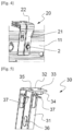
- a screw 2 passing through this oblong hole 26 as well as this circular orifice 14 and being partially screwed into the nut 15 ensures the pre-holding of the lateral fixing bracket 20 against the beam 11 while allowing a certain vertical movement of this bracket 20 before its final fixing by the complete screwing of this screw 2, as illustrated in the Figure 4 .
- Each lateral fixing bracket 20 also comprises a tab 27 projecting horizontally from the first vertical wall 21 above the level of the oblong hole 26 and on the same side as the second horizontal wall 22.
- this tongue 27 the width of which is advantageously between 5 and 7 mm, passes through a respective oblong vertical light 16 arranged on a corresponding lateral portion of the beam 11 near a circular orifice 14 (see Figure 2 ).
- the oblong vertical hole 26 of each bracket 20 and the oblong vertical slot 16 formed in the corresponding lateral portion of the beam 11 extend over an identical height preferably between 15 and 25 mm, the latter being further configured so that the arrival at the bottom (respectively top) stop of the screw 2 against the lower (respectively top) edge of the hole 26 corresponds to the arrival at the bottom (respectively top) stop of the tab 27 against the lower (respectively top) edge of the slot 16.
- the oblong slot 16 provided in each lateral portion of the beam 11 has a width slightly greater than that of the tab 27 of a lateral fixing bracket 20, this difference in width being for example between 1 and 2 mm.
- the first vertical wall 21 advantageously comprises at least one stiffening rib 28 extending vertically over its entire height, preferably between the tab 27 and the oblong vertical hole 26.
- each lateral fixing bracket can be replaced by a boss projecting from the first vertical wall on the same side as the second horizontal wall and passing through an oblong vertical slot provided on a corresponding lateral portion of the beam.
- the front bumper structural subassembly 1 may also include a central fixing bracket 30 produced by folding from a sheet of metal sheet (advantageously in an aluminum alloy) previously cut and intended to be fixed on the central portion of the beam 11 of this bumper reinforcement 10 in order to allow the bumper support frame (or the bumper directly) to be secured there by screwing in order to avoid its weakening when its mass is significant (case of vehicles having for example a width greater than the average).
- a central fixing bracket 30 produced by folding from a sheet of metal sheet (advantageously in an aluminum alloy) previously cut and intended to be fixed on the central portion of the beam 11 of this bumper reinforcement 10 in order to allow the bumper support frame (or the bumper directly) to be secured there by screwing in order to avoid its weakening when its mass is significant (case of vehicles having for example a width greater than the average).
- this central fixing bracket 30 comprises a first vertical wall 31 attached against the front face of the central portion of the beam 11, as well as a second horizontal wall 32 extending from the upper edge of the first vertical wall 31 perpendicular to the latter.
- this second horizontal wall 32 comprises a circular orifice 33 on the periphery of which a nut 34 is fitted, so as to allow the support frame of the bumper (or directly of the bumper) to be fixed by screwing.
- This second horizontal wall 32 also advantageously comprises at least one rectangular orifice 35 intended to be crossed by an indexing pin coming from the support frame of the bumper (or directly from the bumper) of the vehicle so as to ensure its pre-maintenance.
- the first vertical wall 31 has, in its lower part, an oblong vertical hole 36 positioned opposite a respective circular orifice (not visible) provided on the central portion of the beam 11 and on the periphery of which is implanted a crimped nut (also not visible).
- a screw 3 passing through this oblong hole 36 as well as this circular orifice and being partially screwed into this nut ensures the pre-holding of the central fixing bracket 30 against the beam 11 while allowing a certain vertical movement of this bracket 30 before its final fixing by the complete screwing of this screw 3.
- the central fixing bracket 30 also comprises two tabs 37 projecting horizontally from the first vertical wall 31 above the level of the oblong hole 36 and on the same side as the second horizontal wall 32.
- this different way of ensuring the anti-rotation of this central bracket 30 limits its possibilities of vertical adjustment by imposing a minimum spacing between the top of the beam 11 and the second horizontal wall 32, this choice makes it possible to avoid having to weaken the beam 11 in its central portion most sensitive to frontal impacts by making an oblong vertical hole there.
- the front bumper structural subassembly 1 may be devoid of such a central fixing bracket.
Landscapes
- Engineering & Computer Science (AREA)
- Mechanical Engineering (AREA)
- Body Structure For Vehicles (AREA)
Claims (10)
- Kraftfahrzeug- Bauuntergruppe (1) mit einer Stoßfängerverstärkung (10), die einen Balken (11) und zwei seitliche Befestigungswinkel (20) aufweist, von denen jeder eine erste vertikale Wand (21), die an der Vorderseite eines entsprechenden Seitenabschnitts des Balkens (11) angebracht ist, und eine zweite horizontale Wand (22) aufweist, die sich von der Oberkante der ersten vertikalen Wand (21) über dem Balken (11) erstreckt, wobei die erste vertikale Wand (21) ein vertikales Langloch aufweist (26), die gegenüber einer entsprechenden kreisförmigen Öffnung (14) an einem entsprechenden seitlichen Abschnitt des Balkens (11) angeordnet ist, wobei das vertikale Langloch (26) und die kreisförmige Öffnung (14) von einer Schraube (2) durchsetzt sind, die teilweise in eine Mutter (15) eingeschraubt ist, sodass der seitliche Befestigungswinkel (20) an dem Balken (11) vorgehalten wird, während gleichzeitig ein gewisses vertikales Auslenken des seitlichen Befestigungswinkels (20) vor dessen endgültiger Befestigung durch vollständiges Einschrauben der Schraube (2) ermöglicht wird, Seitenbefestigungswinkel (20), der außerdem ein Element (27) aufweist, das von der ersten vertikalen Wand (21) auf der gleichen Seite wie die zweite horizontale Wand (22) vorsteht;
das Merkmal ist, dass das vorspringende Element (27) jedes seitlichen Befestigungswinkels (20) durch ein jeweiliges längliches vertikales Lumen (16) verläuft, dass an einem entsprechenden seitlichen Abschnitt des Balkens (11) in der Nähe einer kreisförmigen Öffnung (14) ausgebildet ist. - Bauuntergruppe (1) nach Anspruch 1, dadurch gekennzeichnet, dass sich das vertikale Langloch (26) jedes seitlichen Befestigungswinkels (20) und des vertikalen Lichts (16) in dem entsprechenden seitlichen Abschnitt des Balkens (11) über eine identische Höhe erstrecken, wobei die letzteren (26, 16) ferner so konfiguriert sind, dass die niedrige (bzw. hohe) Anschlagbewegung einer Schraube (2) gegen die untere (bzw. obere) Kante des Lochs (26) der unteren (bzw. hohen) Anschlagbewegung entspricht des vorspringenden Elements (27) an der unteren (bzw. oberen) Kante der Öffnung (16).
- Bauuntergruppe (1) nach Anspruch 2, dadurch gekennzeichnet, dass die Höhe zwischen 15 und 25 mm liegt.
- Bauuntergruppe (1) nach einem der Ansprüche 1 bis 3, dadurch gekennzeichnet, dass das vorspringende Element durch eine Zunge (27) gebildet ist.
- Bauuntergruppe (1) nach Anspruch 4, dadurch gekennzeichnet, dass das längliche Lumen (16) in jedem Seitenabschnitt des Balkens (11) eine Breite aufweist, die 1 bis 2 mm größer ist als die der Zunge (27) eines seitlichen Befestigungswinkels (20).
- Bauuntergruppe (1) nach einem der Ansprüche 4 oder 5, dadurch gekennzeichnet, dass die Zunge (27) jedes seitlichen Befestigungswinkels (20) durch Schneiden und Falten in seiner ersten vertikalen Wand (21) hergestellt ist.
- Bauuntergruppe (1) nach einem der Ansprüche 4 bis 6, dadurch gekennzeichnet, dass die Zunge (27) und das vertikale Langloch (26) jedes seitlichen Befestigungswinkels (20) seitlich voneinander versetzt sind.
- Bauuntergruppe (1) nach einem der Ansprüche 1 bis 7, dadurch gekennzeichnet, dass die erste vertikale Wand (21) jedes seitlichen Befestigungswinkels (20) mindestens eine Versteifungsrippe (28) aufweist, die sich vertikal über ihre gesamte Höhe erstreckt.
- Bauuntergruppe (1) nach einem der Ansprüche 1 bis 8, dadurch gekennzeichnet, dass sie einen zentralen Befestigungswinkel (30) aufweist, der eine erste vertikale Wand (31), die gegen die Vorderseite des zentralen Abschnitts des Balkens (11) angebracht ist, sowie eine zweite horizontale Wand (32) aufweist, die sich von der Oberkante der ersten vertikalen Wand (31) über dem Balken (11) erstreckt, wobei die erste vertikale Wand (31) dieses zentralen Befestigungswinkels (30) ein vertikales Langloch (36) aufweist gegenüber einer entsprechenden kreisförmigen Öffnung am Mittelteil des Balkens (11) angeordnet ist, wobei das vertikale Langloch (36) und die kreisförmige Öffnung von einer Schraube (3) durchsetzt sind, die teilweise in eine Mutter eingeschraubt ist, um das Vorhalten des zentralen Befestigungswinkels (30) gegen den Balken (11) zu gewährleisten, während gleichzeitig ein gewisses vertikales Auslenken des zentralen Befestigungswinkels (30) vor dessen endgültiger Befestigung durch vollständiges Einschrauben der Schraube (3) möglich ist, wobei der zentrale Befestigungswinkel (30) auch zwei vorstehende Zungen (37) aufweist Horizontal von der ersten vertikalen Wand (31) auf derselben Seite wie die zweite horizontale Wand (32) und auf der Oberseite des Balkens (11) aufliegend.
- Kraftfahrzeug mit einer strukturellen Bauuntergruppe (1) nach einem der Ansprüche 1 bis 9.
Applications Claiming Priority (2)
| Application Number | Priority Date | Filing Date | Title |
|---|---|---|---|
| FR2111773A FR3128918B1 (fr) | 2021-11-05 | 2021-11-05 | Sous-ensemble structurel de pare-chocs comportant un renfort de pare-chocs et deux équerres de fixation latérales |
| PCT/FR2022/051907 WO2023079223A1 (fr) | 2021-11-05 | 2022-10-11 | Sous-ensemble structurel de pare-chocs comportant un renfort de pare-chocs et deux équerres de fixation latérales |
Publications (2)
| Publication Number | Publication Date |
|---|---|
| EP4426590A1 EP4426590A1 (de) | 2024-09-11 |
| EP4426590B1 true EP4426590B1 (de) | 2025-06-18 |
Family
ID=80122508
Family Applications (1)
| Application Number | Title | Priority Date | Filing Date |
|---|---|---|---|
| EP22802205.9A Active EP4426590B1 (de) | 2021-11-05 | 2022-10-11 | Strukturelle unteranordnung eines stossfängers mit einer stossfängerverstärkung und zwei seitlichen montagekonsolen |
Country Status (4)
| Country | Link |
|---|---|
| EP (1) | EP4426590B1 (de) |
| CN (1) | CN118201814A (de) |
| FR (1) | FR3128918B1 (de) |
| WO (1) | WO2023079223A1 (de) |
Families Citing this family (2)
| Publication number | Priority date | Publication date | Assignee | Title |
|---|---|---|---|---|
| FR3150487A1 (fr) * | 2023-06-28 | 2025-01-03 | Psa Automobiles Sa | Vehicule avec systeme d’absorption de chocs avant comprenant des absorbeurs lateraux |
| FR3152455A1 (fr) * | 2023-08-30 | 2025-03-07 | Psa Automobiles Sa | Véhicule automobile dont le renfort de peau de pare-chocs est maintenu et/ou fixé sur les projecteurs avant |
Family Cites Families (5)
| Publication number | Priority date | Publication date | Assignee | Title |
|---|---|---|---|---|
| GB1372694A (en) | 1970-10-22 | 1974-11-06 | Iws Nominee Co Ltd | Textile finishing |
| DE102009029811B4 (de) * | 2009-06-18 | 2015-04-02 | Hbpo Gmbh | Frontendmodul |
| FR3063262B1 (fr) | 2017-02-24 | 2019-04-05 | Peugeot Citroen Automobiles Sa | Dispositif de fixation d’un pare-chocs sur une poutre de pare-chocs de vehicule automobile |
| DE102017109887B4 (de) * | 2017-05-09 | 2024-05-29 | Dr. Ing. H.C. F. Porsche Aktiengesellschaft | Fahrzeugheck eines Kraftfahrzeuges |
| FR3104509B1 (fr) * | 2019-12-11 | 2022-05-06 | Psa Automobiles Sa | Véhicule automobile comportant une armature de pare-chocs |
-
2021
- 2021-11-05 FR FR2111773A patent/FR3128918B1/fr active Active
-
2022
- 2022-10-11 EP EP22802205.9A patent/EP4426590B1/de active Active
- 2022-10-11 CN CN202280073532.0A patent/CN118201814A/zh active Pending
- 2022-10-11 WO PCT/FR2022/051907 patent/WO2023079223A1/fr not_active Ceased
Also Published As
| Publication number | Publication date |
|---|---|
| FR3128918B1 (fr) | 2023-09-29 |
| WO2023079223A1 (fr) | 2023-05-11 |
| EP4426590A1 (de) | 2024-09-11 |
| CN118201814A (zh) | 2024-06-14 |
| FR3128918A1 (fr) | 2023-05-12 |
Similar Documents
| Publication | Publication Date | Title |
|---|---|---|
| EP4426590B1 (de) | Strukturelle unteranordnung eines stossfängers mit einer stossfängerverstärkung und zwei seitlichen montagekonsolen | |
| EP2744698B1 (de) | Kraftfahrzeugkarosserie mit einer versteifungsvorrichtung | |
| EP4077105A1 (de) | Aufbau eines kraftfahrzeug-hinterteils, das mit seitenelementen und längselementen ausgerüstet ist | |
| FR2931417A1 (fr) | Dispositif d'absorption de choc et face avant comportant un tel dispositif | |
| EP3820743B1 (de) | Aus einem stück expandiertem polymermaterial mit stossabsorbierenden zonen hergestellte luftführung für ein kraftfahrzeug | |
| EP4100283B1 (de) | Frontschutzformteil für ein kraftfahrzeug mit einer radar- und frontstruktur eines fahrzeugs mit einem solchen schutzformteil | |
| FR3138106A1 (fr) | Soubassement de caisse pour véhicule hybride ou électrique doté de longerons latéraux renforcés | |
| EP2763885B1 (de) | Querträgeranordnung eines kraftfahrzeugarmaturenbretts und kraftfahrzeug mit einer solchen anordnung | |
| WO2008061824A1 (fr) | Ensemble d'absorption de chocs pour vehicule automobile et face avant correspondante | |
| EP4359287B1 (de) | Strukturanordnung für die frontseite eines kraftfahrzeugs | |
| EP4301629B1 (de) | Stossfängerverstärkungsschnittstellenhalterung für ein kraftfahrzeug | |
| FR2911824A1 (fr) | Ensemble d'absorption de chocs pour projecteur de vehicule automobile | |
| FR3139786A1 (fr) | extension de longeronnet pour véhicule automobile | |
| EP2139726B1 (de) | Stossdämpfungssystem für ein motorfahrzeug | |
| EP4341131B1 (de) | Absorptionsvorrichtung mit spannungsarmen schweissnähten für landfahrzeuge | |
| EP4377159B1 (de) | Kraftfahrzeug mit einer einen frontstossfänger aufweisenden karosseriestruktur | |
| EP4001060B1 (de) | Frontstruktur eines kraftfahrzeugs mit frontalaufprallsteuerung mit geringer abdeckung | |
| WO2025202549A1 (fr) | Structure avant de véhicule automobile et véhicule automobile comportant une telle structure avant | |
| EP0289397B1 (de) | Stossstange für Kraftfahrzeug und damit ausgerüstetes Fahrzeug | |
| EP4347321A1 (de) | Halterung zur befestigung zweier fahrzeugvorrichtungen | |
| FR3131717A1 (fr) | Boîtier de projecteur pour véhicule automobile pourvu d’une rampe de guidage | |
| EP1675758A1 (de) | Vorgeformtes chassis-element zur abdämpfung eines fussgängeraufpralls | |
| FR3152479A1 (fr) | Ensemble de passage de roue pour véhicule automobile et véhicule automobile comprenant un tel ensemble | |
| WO2026017526A1 (fr) | Berceau avant de véhicule automobile | |
| WO2023227838A1 (fr) | Structure de caisse de véhicule automobile à déformation contrôlée de l'arc pavillon en cas de choc frontal |
Legal Events
| Date | Code | Title | Description |
|---|---|---|---|
| STAA | Information on the status of an ep patent application or granted ep patent |
Free format text: STATUS: UNKNOWN |
|
| STAA | Information on the status of an ep patent application or granted ep patent |
Free format text: STATUS: THE INTERNATIONAL PUBLICATION HAS BEEN MADE |
|
| PUAI | Public reference made under article 153(3) epc to a published international application that has entered the european phase |
Free format text: ORIGINAL CODE: 0009012 |
|
| STAA | Information on the status of an ep patent application or granted ep patent |
Free format text: STATUS: REQUEST FOR EXAMINATION WAS MADE |
|
| 17P | Request for examination filed |
Effective date: 20240503 |
|
| AK | Designated contracting states |
Kind code of ref document: A1 Designated state(s): AL AT BE BG CH CY CZ DE DK EE ES FI FR GB GR HR HU IE IS IT LI LT LU LV MC ME MK MT NL NO PL PT RO RS SE SI SK SM TR |
|
| DAV | Request for validation of the european patent (deleted) | ||
| DAX | Request for extension of the european patent (deleted) | ||
| GRAP | Despatch of communication of intention to grant a patent |
Free format text: ORIGINAL CODE: EPIDOSNIGR1 |
|
| STAA | Information on the status of an ep patent application or granted ep patent |
Free format text: STATUS: GRANT OF PATENT IS INTENDED |
|
| INTG | Intention to grant announced |
Effective date: 20250213 |
|
| GRAS | Grant fee paid |
Free format text: ORIGINAL CODE: EPIDOSNIGR3 |
|
| GRAA | (expected) grant |
Free format text: ORIGINAL CODE: 0009210 |
|
| STAA | Information on the status of an ep patent application or granted ep patent |
Free format text: STATUS: THE PATENT HAS BEEN GRANTED |
|
| AK | Designated contracting states |
Kind code of ref document: B1 Designated state(s): AL AT BE BG CH CY CZ DE DK EE ES FI FR GB GR HR HU IE IS IT LI LT LU LV MC ME MK MT NL NO PL PT RO RS SE SI SK SM TR |
|
| REG | Reference to a national code |
Ref country code: GB Ref legal event code: FG4D Free format text: NOT ENGLISH |
|
| REG | Reference to a national code |
Ref country code: CH Ref legal event code: EP |
|
| REG | Reference to a national code |
Ref country code: DE Ref legal event code: R096 Ref document number: 602022016202 Country of ref document: DE |
|
| REG | Reference to a national code |
Ref country code: DE Ref legal event code: R084 Ref document number: 602022016202 Country of ref document: DE |
|
| REG | Reference to a national code |
Ref country code: CH Ref legal event code: EP |
|
| REG | Reference to a national code |
Ref country code: IE Ref legal event code: FG4D Free format text: LANGUAGE OF EP DOCUMENT: FRENCH |
|
| PG25 | Lapsed in a contracting state [announced via postgrant information from national office to epo] |
Ref country code: FI Free format text: LAPSE BECAUSE OF FAILURE TO SUBMIT A TRANSLATION OF THE DESCRIPTION OR TO PAY THE FEE WITHIN THE PRESCRIBED TIME-LIMIT Effective date: 20250618 |
|
| REG | Reference to a national code |
Ref country code: LT Ref legal event code: MG9D |
|
| PG25 | Lapsed in a contracting state [announced via postgrant information from national office to epo] |
Ref country code: NO Free format text: LAPSE BECAUSE OF FAILURE TO SUBMIT A TRANSLATION OF THE DESCRIPTION OR TO PAY THE FEE WITHIN THE PRESCRIBED TIME-LIMIT Effective date: 20250918 Ref country code: GR Free format text: LAPSE BECAUSE OF FAILURE TO SUBMIT A TRANSLATION OF THE DESCRIPTION OR TO PAY THE FEE WITHIN THE PRESCRIBED TIME-LIMIT Effective date: 20250919 |
|
| PG25 | Lapsed in a contracting state [announced via postgrant information from national office to epo] |
Ref country code: BG Free format text: LAPSE BECAUSE OF FAILURE TO SUBMIT A TRANSLATION OF THE DESCRIPTION OR TO PAY THE FEE WITHIN THE PRESCRIBED TIME-LIMIT Effective date: 20250618 |
|
| PG25 | Lapsed in a contracting state [announced via postgrant information from national office to epo] |
Ref country code: HR Free format text: LAPSE BECAUSE OF FAILURE TO SUBMIT A TRANSLATION OF THE DESCRIPTION OR TO PAY THE FEE WITHIN THE PRESCRIBED TIME-LIMIT Effective date: 20250618 |
|
| PGFP | Annual fee paid to national office [announced via postgrant information from national office to epo] |
Ref country code: FR Payment date: 20250924 Year of fee payment: 4 |
|
| PG25 | Lapsed in a contracting state [announced via postgrant information from national office to epo] |
Ref country code: RS Free format text: LAPSE BECAUSE OF FAILURE TO SUBMIT A TRANSLATION OF THE DESCRIPTION OR TO PAY THE FEE WITHIN THE PRESCRIBED TIME-LIMIT Effective date: 20250918 |
|
| REG | Reference to a national code |
Ref country code: NL Ref legal event code: MP Effective date: 20250618 |
|
| PG25 | Lapsed in a contracting state [announced via postgrant information from national office to epo] |
Ref country code: LV Free format text: LAPSE BECAUSE OF FAILURE TO SUBMIT A TRANSLATION OF THE DESCRIPTION OR TO PAY THE FEE WITHIN THE PRESCRIBED TIME-LIMIT Effective date: 20250618 |
|
| PG25 | Lapsed in a contracting state [announced via postgrant information from national office to epo] |
Ref country code: NL Free format text: LAPSE BECAUSE OF FAILURE TO SUBMIT A TRANSLATION OF THE DESCRIPTION OR TO PAY THE FEE WITHIN THE PRESCRIBED TIME-LIMIT Effective date: 20250618 |
|
| PG25 | Lapsed in a contracting state [announced via postgrant information from national office to epo] |
Ref country code: PT Free format text: LAPSE BECAUSE OF FAILURE TO SUBMIT A TRANSLATION OF THE DESCRIPTION OR TO PAY THE FEE WITHIN THE PRESCRIBED TIME-LIMIT Effective date: 20251020 |
|
| REG | Reference to a national code |
Ref country code: AT Ref legal event code: MK05 Ref document number: 1803930 Country of ref document: AT Kind code of ref document: T Effective date: 20250618 |
|
| PG25 | Lapsed in a contracting state [announced via postgrant information from national office to epo] |
Ref country code: IS Free format text: LAPSE BECAUSE OF FAILURE TO SUBMIT A TRANSLATION OF THE DESCRIPTION OR TO PAY THE FEE WITHIN THE PRESCRIBED TIME-LIMIT Effective date: 20251018 |
|
| PGFP | Annual fee paid to national office [announced via postgrant information from national office to epo] |
Ref country code: DE Payment date: 20250923 Year of fee payment: 4 |
|
| PG25 | Lapsed in a contracting state [announced via postgrant information from national office to epo] |
Ref country code: AT Free format text: LAPSE BECAUSE OF FAILURE TO SUBMIT A TRANSLATION OF THE DESCRIPTION OR TO PAY THE FEE WITHIN THE PRESCRIBED TIME-LIMIT Effective date: 20250618 Ref country code: SM Free format text: LAPSE BECAUSE OF FAILURE TO SUBMIT A TRANSLATION OF THE DESCRIPTION OR TO PAY THE FEE WITHIN THE PRESCRIBED TIME-LIMIT Effective date: 20250618 |
|
| PG25 | Lapsed in a contracting state [announced via postgrant information from national office to epo] |
Ref country code: CZ Free format text: LAPSE BECAUSE OF FAILURE TO SUBMIT A TRANSLATION OF THE DESCRIPTION OR TO PAY THE FEE WITHIN THE PRESCRIBED TIME-LIMIT Effective date: 20250618 |
|
| PG25 | Lapsed in a contracting state [announced via postgrant information from national office to epo] |
Ref country code: PL Free format text: LAPSE BECAUSE OF FAILURE TO SUBMIT A TRANSLATION OF THE DESCRIPTION OR TO PAY THE FEE WITHIN THE PRESCRIBED TIME-LIMIT Effective date: 20250618 |
|
| PG25 | Lapsed in a contracting state [announced via postgrant information from national office to epo] |
Ref country code: EE Free format text: LAPSE BECAUSE OF FAILURE TO SUBMIT A TRANSLATION OF THE DESCRIPTION OR TO PAY THE FEE WITHIN THE PRESCRIBED TIME-LIMIT Effective date: 20250618 |
|
| PG25 | Lapsed in a contracting state [announced via postgrant information from national office to epo] |
Ref country code: SK Free format text: LAPSE BECAUSE OF FAILURE TO SUBMIT A TRANSLATION OF THE DESCRIPTION OR TO PAY THE FEE WITHIN THE PRESCRIBED TIME-LIMIT Effective date: 20250618 |
|
| PG25 | Lapsed in a contracting state [announced via postgrant information from national office to epo] |
Ref country code: ES Free format text: LAPSE BECAUSE OF FAILURE TO SUBMIT A TRANSLATION OF THE DESCRIPTION OR TO PAY THE FEE WITHIN THE PRESCRIBED TIME-LIMIT Effective date: 20250618 |
|
| PG25 | Lapsed in a contracting state [announced via postgrant information from national office to epo] |
Ref country code: RO Free format text: LAPSE BECAUSE OF FAILURE TO SUBMIT A TRANSLATION OF THE DESCRIPTION OR TO PAY THE FEE WITHIN THE PRESCRIBED TIME-LIMIT Effective date: 20250618 |
|
| PG25 | Lapsed in a contracting state [announced via postgrant information from national office to epo] |
Ref country code: DK Free format text: LAPSE BECAUSE OF FAILURE TO SUBMIT A TRANSLATION OF THE DESCRIPTION OR TO PAY THE FEE WITHIN THE PRESCRIBED TIME-LIMIT Effective date: 20250618 |
|
| PG25 | Lapsed in a contracting state [announced via postgrant information from national office to epo] |
Ref country code: IT Free format text: LAPSE BECAUSE OF FAILURE TO SUBMIT A TRANSLATION OF THE DESCRIPTION OR TO PAY THE FEE WITHIN THE PRESCRIBED TIME-LIMIT Effective date: 20250618 |
|
| PLBE | No opposition filed within time limit |
Free format text: ORIGINAL CODE: 0009261 |
|
| STAA | Information on the status of an ep patent application or granted ep patent |
Free format text: STATUS: NO OPPOSITION FILED WITHIN TIME LIMIT |
|
| REG | Reference to a national code |
Ref country code: CH Ref legal event code: L10 Free format text: ST27 STATUS EVENT CODE: U-0-0-L10-L00 (AS PROVIDED BY THE NATIONAL OFFICE) Effective date: 20260430 |