EP4101584A1 - Dispositif de préhension d'éléments oblongs de fixation à partir d'un entrepôt désordonné - Google Patents
Dispositif de préhension d'éléments oblongs de fixation à partir d'un entrepôt désordonné Download PDFInfo
- Publication number
- EP4101584A1 EP4101584A1 EP22177228.8A EP22177228A EP4101584A1 EP 4101584 A1 EP4101584 A1 EP 4101584A1 EP 22177228 A EP22177228 A EP 22177228A EP 4101584 A1 EP4101584 A1 EP 4101584A1
- Authority
- EP
- European Patent Office
- Prior art keywords
- gripping
- elements
- elongate
- gripping elements
- disordered
- Prior art date
- Legal status (The legal status is an assumption and is not a legal conclusion. Google has not performed a legal analysis and makes no representation as to the accuracy of the status listed.)
- Pending
Links
Images
Classifications
-
- B—PERFORMING OPERATIONS; TRANSPORTING
- B23—MACHINE TOOLS; METAL-WORKING NOT OTHERWISE PROVIDED FOR
- B23Q—DETAILS, COMPONENTS, OR ACCESSORIES FOR MACHINE TOOLS, e.g. ARRANGEMENTS FOR COPYING OR CONTROLLING; MACHINE TOOLS IN GENERAL CHARACTERISED BY THE CONSTRUCTION OF PARTICULAR DETAILS OR COMPONENTS; COMBINATIONS OR ASSOCIATIONS OF METAL-WORKING MACHINES, NOT DIRECTED TO A PARTICULAR RESULT
- B23Q7/00—Arrangements for handling work specially combined with or arranged in, or specially adapted for use in connection with, machine tools, e.g. for conveying, loading, positioning, discharging, sorting
- B23Q7/04—Arrangements for handling work specially combined with or arranged in, or specially adapted for use in connection with, machine tools, e.g. for conveying, loading, positioning, discharging, sorting by means of grippers
-
- B—PERFORMING OPERATIONS; TRANSPORTING
- B23—MACHINE TOOLS; METAL-WORKING NOT OTHERWISE PROVIDED FOR
- B23Q—DETAILS, COMPONENTS, OR ACCESSORIES FOR MACHINE TOOLS, e.g. ARRANGEMENTS FOR COPYING OR CONTROLLING; MACHINE TOOLS IN GENERAL CHARACTERISED BY THE CONSTRUCTION OF PARTICULAR DETAILS OR COMPONENTS; COMBINATIONS OR ASSOCIATIONS OF METAL-WORKING MACHINES, NOT DIRECTED TO A PARTICULAR RESULT
- B23Q17/00—Arrangements for observing, indicating or measuring on machine tools
- B23Q17/24—Arrangements for observing, indicating or measuring on machine tools using optics or electromagnetic waves
- B23Q17/248—Arrangements for observing, indicating or measuring on machine tools using optics or electromagnetic waves using special electromagnetic means or methods
- B23Q17/249—Arrangements for observing, indicating or measuring on machine tools using optics or electromagnetic waves using special electromagnetic means or methods using image analysis, e.g. for radar, infrared or array camera images
-
- B—PERFORMING OPERATIONS; TRANSPORTING
- B65—CONVEYING; PACKING; STORING; HANDLING THIN OR FILAMENTARY MATERIAL
- B65G—TRANSPORT OR STORAGE DEVICES, e.g. CONVEYORS FOR LOADING OR TIPPING, SHOP CONVEYOR SYSTEMS OR PNEUMATIC TUBE CONVEYORS
- B65G47/00—Article or material-handling devices associated with conveyors; Methods employing such devices
- B65G47/74—Feeding, transfer, or discharging devices of particular kinds or types
- B65G47/90—Devices for picking-up and depositing articles or materials
-
- B—PERFORMING OPERATIONS; TRANSPORTING
- B25—HAND TOOLS; PORTABLE POWER-DRIVEN TOOLS; MANIPULATORS
- B25J—MANIPULATORS; CHAMBERS PROVIDED WITH MANIPULATION DEVICES
- B25J9/00—Program-controlled manipulators
- B25J9/16—Program controls
- B25J9/1612—Program controls characterised by the hand, wrist, grip control
Definitions
- the present invention relates to a device for picking up elongate fasteners from a disordered store according to the preamble of claim 1.
- Tool magazines are already known ( DE 10 2009 016 372 A1 , DE 10 2015 121 287 A1 ) in which elongated fasteners are sorted and stored with a defined position and orientation for automated further processing.
- the elongated fasteners are screws, bolts or rivets. These are guided directly from the position in the tool magazine by means of appropriate processing tools in such a way that these elongate fastening elements are mounted in the process.
- tool magazines are loaded "by hand” in that the elongate fastening elements are gripped by a worker and individually inserted into the tool magazine at the respective receiving position with the correct orientation.
- the present invention is based on the object of simplifying the equipping of a tool magazine.
- the device has a gripping device which has two elongate gripping elements and a controllable actuating mechanism for the automated actuation of the two gripping elements.
- the two gripping elements can thus be opened and closed via the actuating mechanism in automated operation.
- the device has a camera system and a device for image evaluation. The position and the orientation of the elongate fastening elements in the disordered store can be recognized with the device for image evaluation.
- the device also has a regulating or control device with control means for controlling a positioning unit for the gripping device and control means for controlling the opening and closing of the two gripping elements depending on the detected position and orientation of the elongated fasteners.
- the two gripping elements each have a gripping area. The gripping areas are moved towards one another when the two gripping elements are closed, so that in the closed position they grip an elongate fastening element located in the gripping area in a non-positive manner,
- This configuration results in a number of advantages.
- One advantage is that the tool magazine can be loaded in automated operation with a sufficiently short cycle time.
- the short cycle time is essentially due to the fact that exactly one of the elongated fastening elements is gripped with the gripping device during a gripping process with a high degree of certainty.
- this elongate fastener is gripped in a defined position and orientation relative to the two gripping elements. This enables quick and safe placement in the tool magazine at the correct position and with the orientation direction.
- the two gripping elements can be opened and closed by moving the two gripping elements away from one another or towards one another with a linear movement in the sense of a parallel displacement. Instead of this linear movement, the two gripping elements can also be opened and closed with a tong-like movement in the sense of the rotary movement of the tong arms during opening and closing.
- the interaction of the features of claim 1 can be explained as follows.
- the position and the orientation of the elongate fastening elements in the unordered store are recognized by the camera system and the device for image evaluation.
- the regulation or control device with the control means for the positioning of the gripping device and the controllable actuating mechanism for controlled the opening and closing of the two gripping elements. This means that the gripping device is quickly aligned to grip an elongate fastener.
- the control is advantageously carried out in such a way that not only the position and orientation of the elongate fastening elements are recognized.
- an assessment is made immediately as to which of the elongate fastening elements is sufficiently exposed so that this elongate fastening element can be gripped.
- the gripping device is then positioned in relation to this elongate fastening element.
- a “tilt signal” can be sent by the device for image evaluation.
- a mixing device is then started as a function of this canting signal.
- the mixing device can be a stirring arm, for example, which stirs the disordered bearing in order to solve this canting of the elongate fastening elements.
- the random storage storage box
- the problem can arise that the elongate fastening elements continue to "settle" and tilt further.
- the mixing device it is also possible, as the mixing device, to position an electromagnet that can be switched on and off above the storage container for the elongate fastening elements.
- the solenoid When the solenoid is energized, the elongate fasteners are lifted out of the storage bin. After the electromagnet is switched off, the elongate fasteners fall back into the storage container. This also makes it possible to solve a canting of the elongate fastening elements.
- the two gripping members of the gripping device are opened sufficiently prior to "dipping" into the disordered store to allow the elongate fastener to fit between the two gripping members when the two gripping members are slid over the fastener.
- This "immersion” does not necessarily mean that the gripping element is moved from above with the gripping elements pointing downwards.
- it may also make sense to align the two gripping elements essentially horizontally (possibly directed slightly downwards) and move them in a horizontal direction over the to push to gripping elongated fastener.
- Such a sequence of movements can be useful if the elongate fastening element to be gripped lies in the disordered store in such a way that its longitudinal axis is oriented essentially vertically. Especially when the elongate fastening element to be gripped lies essentially vertically in the disordered storage area, a sequence of movements can also be useful in which the gripping device is aligned over the elongate fastening element to be gripped in such a way that the semicircular recesses of the two gripping elements are just above the elongated fastener are located.
- the direction of movement of the gripping element thus depends on the orientation of the elongate fastener to be gripped.
- the gripping device is closed when the elongate fastening element is in the area of the semicircular recesses of the two gripping elements.
- the design of the gripping area of the two gripping elements advantageously ensures that several elongated fastening elements are only rarely gripped at the same time. If the gripping device is opened just far enough for the elongate fastening element to be gripped to fit between the two gripping elements, it is largely avoided that further elongate fastening elements are pushed between the two gripping elements before the gripping device is closed.
- the gripping elements In addition to the gripping area, the gripping elements also have a push-off surface. This forms an edge at the front end of the respective gripping element, in that this disengagement surface meets the gripping area there.
- the semicircular recess in the gripping elements results in a target position for the elongated fastening element to be gripped.
- this target position is defined both with regard to the position of the elongate fastening element in the gripping device and with regard to the orientation of the elongate fastening element to be gripped relative to the orientation of the gripping elements.
- the elongate fastening element can be easily attached to the intended position and with the specified orientation in the tool magazine can be inserted.
- the elongate fastening element is oriented such that its longitudinal direction is oriented to the longitudinal direction of the two gripping elements.
- the camera system and the device for image evaluation detect whether the elongate fastening element is correctly oriented relative to the momentary orientation of the gripping element. If the elongate fastening element is, for example, a screw with the head at the top, the gripping device must first be rotated 180 degrees about its longitudinal axis so that the screw is inserted into the tool magazine with the correct orientation.
- the semi-circular recess in the gripping elements thus serves not only to prevent several elongate fastening elements from being gripped at the same time.
- These semi-circular recesses in the two gripping elements also give the elongate fastener a well-defined orientation relative to the gripping device when gripped. This facilitates insertion into the tool magazine.
- the constantly differentiable course of the displacement surface from the front edge of the gripping element brings with it the advantage that when the gripping device "dips" into the disordered storage of the elongated fastening elements in the longitudinal direction of the gripping elements, elongated fastening elements that are next to the elongated fastening element to be gripped be pushed to the side and thus do not interfere with the gripping process. If the progression of the release surface could not be continuously differentiated, an elongate fastening element could get caught due to the "crack" in the progression of the surface.
- the two gripping elements can advantageously also have an anti-slip design in the gripping area.
- the surface of the gripping elements can be profiled in the gripping areas and/or have a coating.
- the profiling of the surface can consist, for example, in parallel lines or a grid pattern being engraved into the surface in the gripping area.
- the coating can consist of applying a material to the surface in the gripping area that has a high coefficient of friction ⁇ .
- a material can be rubber, for example. It is also possible to apply a corresponding material and to provide the surface of the material with the profiling.
- the gripping area of the two gripping elements also has a semicircular recess whose longitudinal axis is oriented parallel to the longitudinal direction of the gripping element.
- This recess according to claim 2 intersects the recess according to the description of claim 1 at a right angle. It is therefore two semi-cylinders that lie inside each other.
- the gripping device can be moved in such a way that an elongate fastening element to be gripped is inserted between the two gripping elements in such a way that the gripping device and thus also the two gripping elements are pushed over the elongate fastening element in their longitudinal direction.
- the two gripping members When the two gripping members are slid far enough over the elongate fastener, the two gripping members can be closed.
- the continuously differentiable course of the disengagement surface is convex when the disengagement surface is viewed from above.
- the round recess in the gripping area according to claim 1 can advantageously be arranged close to the front edge of the gripping element.
- the device further comprises a mixing device for carrying out a mixing process in the disordered storage of the elongate fastening elements.
- such a mixing device can also be usefully used when the elongate fastening elements are to be gripped with a differently configured gripping device.
- the aim of the mixing device is to solve tilting of the elongated fastening elements in the disordered storage/storage container. It is obvious that this measure is independent of how the elongate fastening elements are subsequently gripped by a gripping device. It is therefore reserved to file a divisional application with a claim wording that is based solely on the mixing device (i.e. independent of the gripping device otherwise) and a corresponding method claim that relates to the operation of this mixing device.
- the mixing device can, for example, be activated at certain time intervals in order to mix the elongate fastening elements in the storage container.
- the mixing device can also be set in motion according to claim 5 depending on a control signal from the device for image evaluation if the image evaluation shows that the elongate fastening elements are tilted in the disordered store.
- the mixing device can also be set in motion, for example, if the gripping device, after the start of a gripping process, requires a period of time which is above a threshold value before it can grip an elongate fastening element. Recognizing such a period of time can also be a measure that it makes sense to mix up the disordered storage of the elongate fastening elements.
- the mixing device can consist of an electromagnet, for example.
- This electromagnet can be switched on and off.
- the electromagnet is like that movable that this is in a rest position on the side or below the disordered camp. From there, the electromagnet can be moved into a working position in which the electromagnet is arranged above the disordered bearing. In the rest position, the electromagnet is positioned so as not to impede movements of the gripping device when manipulating the elongate fasteners.
- the electromagnet is moved from the rest position to the working position. In the working position, the electromagnet is switched on. This causes the elongate fasteners in the disordered store to be attracted by the electromagnet and lifted out of the disordered store. The electromagnet is then switched off again. The elongate fasteners then fall back from the electromagnet (with a "new" arrangement) into the disordered store. Statistically, the elongate fasteners then have less order in the disordered store than before and are therefore easier to grip individually. The electromagnet is moved back to its rest position.
- the transition from the rest position to the working position and vice versa can be realized by a circular movement of the electromagnet or by a linear displacement of the electromagnet.
- the mixing device can be a vibrating device, for example.
- this shaking device causes not only a shaking movement in the horizontal direction, but also in the vertical direction. In the case of a shaking movement only in the horizontal direction, it could happen that the elongate fastening elements become even more tilted. If the shaking movement takes place, for example by the disordered bearing being moved abruptly in the vertical direction, the elongate fastening elements are shaken up in such a way that canting between these elongate fastening elements is loosened.
- the elongate fasteners lie in a new arrangement in the disordered store after the shaking process.
- the random storage consists, for example, of a basket that is placed on a suitable vibrating plate. About the movement of the vibrating plate the movement of the elongate fasteners in the disordered store can be triggered in terms of mixing.
- a further alternative configuration of a mixing device consists, for example, in a stirring arm.
- a stirring arm in turn has a rest position and a working position. It is also important here that the agitator arm does not impede the movements of the gripping device in its rest position. In its working position, the agitator arm plunges into the disordered stock. Mixing takes place by moving the agitator arm in the disordered storage area.
- the movement of the mixing arm to carry out the mixing process can be a longitudinal movement, a circular movement or a tilting movement.
- the agitator arm can be moved from the rest position to the working position by means of a linear movement or by means of a tilting movement. Accordingly, the rabble arm is also moved back from the working position to the rest position.
- the remaining elongate fastening elements can advantageously be gripped with less susceptibility to errors.
- the camera system and the device for image evaluation can be used to detect whether the elongate fastening elements are badly tilted in the disordered storage. It can also be recognized whether the elongate fastening elements may be in an unfavorable arrangement relative to one another, so that they can only be gripped poorly with the gripping device. Also in this case--in which the elongate fastening elements do not necessarily have to be canted--it can be useful to carry out thorough mixing.
- This assessment can be made by the control signal for executing a mixing process.
- the mixing device is activated as a function of the control signal to carry out a mixing process in the sense of mixing the storage space
- the camera system and the device for image evaluation can be used to detect whether the elongate fastening elements in the disordered store are severely tilted.
- This evaluation can be carried out by a control signal for triggering a mixing process.
- the device advantageously has a mixing device which can be controlled as a function of the control signal in the sense of mixing the storage space.
- the remaining elongate fastening elements can advantageously be gripped with less susceptibility to errors.
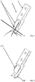
- FIG 1 shows a first embodiment of a gripping element 1.
- This gripping element 1 has two bores in a mounting area 2, which are not provided with reference numbers.
- the gripping element 1 is fastened to a holding element by means of these bores.
- the holding element can be driven, so that a movement of the holding element also moves the gripping element 1 connected to it.
- a gripping area 3 of the gripping element 1 is designated by the reference number 3 .
- this gripping area 3 two semicircular recesses 4 and 5 are shown in the illustrated embodiment.
- the longitudinal axis of the semicircular recess 4 is oriented perpendicularly to the longitudinal axis of the gripping element 1.
- a black line is drawn in the recess 4, which symbolizes the direction of an elongate fastening element that is gripped by this elongate fastening element lying in the semicircular recess 4.
- the longitudinal axis of the semicircular recess 5 is oriented parallel to the longitudinal axis of the gripping element 1.
- a black line is also drawn in the recess 5, which symbolizes the direction of an elongate fastening element that is gripped by this elongate fastening element lying in the semicircular recess 5.
- This push-off surface 6 can be continuously differentiated and runs in such a way that it is oriented away from the gripping area 3 starting from the lower edge of the gripping element 1 .
- This course of the release surface 6 ensures that elongate fastening elements that are adjacent to the elongate fastening element to be gripped are pushed away to the side. In a plan view of the displacement surface 6, this is convexly curved.
- a gripping device has two of the gripping elements 1 as shown in FIG figure 1 on. These are arranged relative to one another in such a way that the two gripping areas 3 interact when the two gripping elements are moved towards each other. This is done with the control of the actuating mechanism for opening and closing the two gripping elements 1.
- the lines 4 and 5 in the representation of figure 1 are only symbolic representations of the orientation of the respective fasteners when gripped.
- the elongate fasteners are cylindrical in the areas where they are gripped.
- the fastening elements have such a radius that the semicircular recesses 4, 5 in the gripping elements 1 are filled to such an extent that the elongate fastening elements are frictionally engaged when the two corresponding gripping elements 1 are pushed together in one direction, in the direction of the surface normal to the gripping areas 3 be grabbed.
- the gripping device consisting of the two corresponding gripping elements 1 can be moved with the positioning unit for the gripping device in such a way that the elongate fastening element is moved to a receiving location in a receiving magazine for several of the fastening elements, so that when the Gripping device, the elongate fastener is placed in the corresponding receiving space in the receiving magazine.
- FIG figure 2 shows another embodiment of a gripping element 1.
- This gripping element 1 is constructed essentially the same as the gripping element in the representation of FIG figure 1 . It can be seen that in the gripping area 3 in the recess 4 the surface has been profiled 202 . A profiling 201 of the surface was also carried out in the recess 5 .
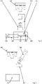
- figure 3 12 shows a mixing device 301 in its working position with a mechanism for moving the mixing device 301 from the working position to the rest position.
- the mechanism for moving the mixing device 301 from the working position to the rest position consists of a hydraulic or pneumatic cylinder 302 which is rotatably mounted at one end (303).
- the piston rod 304 is extended in the position shown.
- a lever system 305, 306 can be seen, which is rotatably mounted at point 307.
- the two rods 305 and 306 of the lever system are fixed to each other so that the angle between the rods 305 and 306 does not change. If the cylinder 302 is controlled in such a way that the piston rod 304 is retracted, the position of the rod 305 changes because the end of the piston rod 304 is articulated on the rod 305 so that it can rotate at point 308 .
- the mixing device 301 is an electromagnet.
- the electromagnet When the electromagnet is switched on, the elongate fasteners are attracted and lifted out of the reservoir. After switching off the electromagnet, the fasteners fall back into the reservoir. The fastening elements then lie in a different arrangement to one another in the reservoir than before they were lifted out by means of the electromagnet.
- FIG. 3 Another camera system 309 can be seen.
- This camera system captures the storage container for the fastening elements.
- the images from the cameras can be evaluated to position a gripping device for gripping a particular elongate fastener from the storage bin.
- the images from the cameras can also be evaluated.
- This assessment may include a criterion as to whether the elongate fasteners are canted relative to each other.
- the assessment can also include whether the fastening elements are positioned relative to one another in such a way that a comparatively complex movement sequence has to be implemented in order to be able to grip an individual fastening element.
- a mixing process can be started.
- the mixing device is first moved into the working position. Then the solenoid is energized to lift the fasteners out of the hopper. The electromagnet is then switched off again so that the fastening elements fall back into the storage container. The mixing device is then moved back into its rest position.
- figure 4 shows a representation of the mixing device 401 in its rest position.
- a hydraulic or pneumatic cylinder 402 can be seen with the piston rod retracted.
- the piston rod of the cylinder 402 is extended.
- the mixing device 401 is lowered obliquely downwards as a result of this linear movement.
- the mixing device is located above the storage container 403, the mixing device 401 has reached the working position.
- the mixing device 401 is again an electromagnet. Mixing takes place again by switching the electromagnet on and then switching it off.
- the piston rod of the cylinder 402 is then retracted again.
- the mixing device 401 is lifted obliquely upwards and thus moved away to the side.
- unimpeded access of the gripping device to the storage container 403 is again possible.
Landscapes
- Engineering & Computer Science (AREA)
- Mechanical Engineering (AREA)
- Physics & Mathematics (AREA)
- Computer Vision & Pattern Recognition (AREA)
- Radar, Positioning & Navigation (AREA)
- Remote Sensing (AREA)
- Electromagnetism (AREA)
- Optics & Photonics (AREA)
- Manipulator (AREA)
- Warehouses Or Storage Devices (AREA)
Applications Claiming Priority (1)
| Application Number | Priority Date | Filing Date | Title |
|---|---|---|---|
| DE202021103093.3U DE202021103093U1 (de) | 2021-06-08 | 2021-06-08 | Vorrichtung zum Greifen länglicher Befestigungselemente aus einem ungeordneten Lager |
Publications (1)
| Publication Number | Publication Date |
|---|---|
| EP4101584A1 true EP4101584A1 (fr) | 2022-12-14 |
Family
ID=82217781
Family Applications (1)
| Application Number | Title | Priority Date | Filing Date |
|---|---|---|---|
| EP22177228.8A Pending EP4101584A1 (fr) | 2021-06-08 | 2022-06-03 | Dispositif de préhension d'éléments oblongs de fixation à partir d'un entrepôt désordonné |
Country Status (2)
| Country | Link |
|---|---|
| EP (1) | EP4101584A1 (fr) |
| DE (1) | DE202021103093U1 (fr) |
Citations (6)
| Publication number | Priority date | Publication date | Assignee | Title |
|---|---|---|---|---|
| EP0951968A2 (fr) * | 1998-04-21 | 1999-10-27 | Fanuc Ltd | Appareil de prise d'objets |
| DE102009016372A1 (de) | 2009-04-07 | 2010-10-21 | Dürr Assembly Products GmbH | Vorrichtung und Verfahren zum automatischen Verbinden zweier Werkstücke |
| CN104057459A (zh) * | 2014-06-25 | 2014-09-24 | 上海发那科机器人有限公司 | 一种机器人智能分拣工件的装置及方法 |
| DE102015121287A1 (de) | 2015-12-07 | 2017-06-08 | Dürr Assembly Products GmbH | Vorrichtung zum automatisierten An- und Abkoppeln eines Werkzeugaufsatzes sowie Verfahren zum automatisierten Verbinden wenigstens zweier Werkstücke |
| JP2019107739A (ja) * | 2017-12-19 | 2019-07-04 | ミネベアミツミ株式会社 | 電動グリッパ装置 |
| WO2020021643A1 (fr) * | 2018-07-24 | 2020-01-30 | 株式会社Fuji | Système de sélection et procédé de sélection d'effecteur terminal |
Family Cites Families (4)
| Publication number | Priority date | Publication date | Assignee | Title |
|---|---|---|---|---|
| DE10213127C1 (de) | 2002-03-23 | 2003-06-05 | Guenther Zimmer | Parallelgreifvorrichtung mit paarweise beweglichen Schlitten |
| WO2009101835A1 (fr) | 2008-02-12 | 2009-08-20 | Honda Motor Co., Ltd. | Dispositif et procédé de montage de tableau de bord de véhicule |
| DE102010037883B4 (de) | 2010-09-30 | 2017-08-10 | Langenstein & Schemann Gmbh | Handhabungsgerät zum Handhaben eines Werkstücks |
| JP5507595B2 (ja) | 2012-02-17 | 2014-05-28 | ファナック株式会社 | ロボットを用いた物品組付け装置 |
-
2021
- 2021-06-08 DE DE202021103093.3U patent/DE202021103093U1/de active Active
-
2022
- 2022-06-03 EP EP22177228.8A patent/EP4101584A1/fr active Pending
Patent Citations (6)
| Publication number | Priority date | Publication date | Assignee | Title |
|---|---|---|---|---|
| EP0951968A2 (fr) * | 1998-04-21 | 1999-10-27 | Fanuc Ltd | Appareil de prise d'objets |
| DE102009016372A1 (de) | 2009-04-07 | 2010-10-21 | Dürr Assembly Products GmbH | Vorrichtung und Verfahren zum automatischen Verbinden zweier Werkstücke |
| CN104057459A (zh) * | 2014-06-25 | 2014-09-24 | 上海发那科机器人有限公司 | 一种机器人智能分拣工件的装置及方法 |
| DE102015121287A1 (de) | 2015-12-07 | 2017-06-08 | Dürr Assembly Products GmbH | Vorrichtung zum automatisierten An- und Abkoppeln eines Werkzeugaufsatzes sowie Verfahren zum automatisierten Verbinden wenigstens zweier Werkstücke |
| JP2019107739A (ja) * | 2017-12-19 | 2019-07-04 | ミネベアミツミ株式会社 | 電動グリッパ装置 |
| WO2020021643A1 (fr) * | 2018-07-24 | 2020-01-30 | 株式会社Fuji | Système de sélection et procédé de sélection d'effecteur terminal |
Non-Patent Citations (1)
| Title |
|---|
| ZHAO JIE ET AL: "Assembly of randomly placed parts realized by using only one robot arm with a general parallel-jaw gripper", 2020 IEEE INTERNATIONAL CONFERENCE ON ROBOTICS AND AUTOMATION (ICRA), IEEE, 31 May 2020 (2020-05-31), pages 5024 - 5030, XP033826731, DOI: 10.1109/ICRA40945.2020.9197396 * |
Also Published As
| Publication number | Publication date |
|---|---|
| DE202021103093U1 (de) | 2022-06-10 |
Similar Documents
| Publication | Publication Date | Title |
|---|---|---|
| DE2727919C2 (de) | Transportgreifer | |
| WO2007012593A1 (fr) | Changeur de capsules de soudage par point | |
| EP3664959B1 (fr) | Procédé et dispositif de fourniture de vis | |
| DE3605099A1 (de) | Vorrichtung zum auswechseln der elektrodenkappen einer roboter-punktschweisszange | |
| EP4101584A1 (fr) | Dispositif de préhension d'éléments oblongs de fixation à partir d'un entrepôt désordonné | |
| DE3816593C2 (fr) | ||
| DE202005020205U1 (de) | Zuführeinrichtung für mechanische Bauteile | |
| DE4010638C2 (fr) | ||
| DE1932411A1 (de) | Vorrichtung zum automatischen Anbringen von Schrauben,Muttern u.dgl. | |
| DE2540644C3 (de) | Längenveränderbare Stange, insbesondere Erdungsstange oder Betätigungsstange für elektrotechnische Einrichtungen | |
| DE3021357C2 (de) | Elastisches Verbindungsglied zwischen einem Arm und einer Magnethaltevorrichtung eines Handhabungsgerätes | |
| CH493261A (de) | Einrichtung zum Ein- und Ausbauen zylindrischer Filterpatronen aus einem Filterbehälter | |
| AT505365B1 (de) | Greifgerät für das maschinelle fassen von teilen aus einer ungeordneten schüttung | |
| DE4017290C2 (fr) | ||
| DE69201469T2 (de) | Verfahren und Vorrichtung zum automatischen Einsetzen von zwei Halb-Kogeln in der konischen Aussparung eines Federtellers. | |
| DE2211386A1 (de) | Greifwerkzeug | |
| DE1531205C3 (de) | Greifer für Rundholzblöcke od. dgl | |
| DE2119602C3 (de) | Vorrichtung zur Zuführung von Lagersteinen bei Steinsetzmaschinen | |
| EP2014602A1 (fr) | Dispositif et procédé pour la saisie mécanique de bûches de bois | |
| DE4100359C2 (de) | Vorrichtung zum Ein- und Auslagern eines Behälters aus einem bzw. in ein Regal | |
| DE1603924C (de) | Vorrichtung zum Einschrauben von Schrauben in Werkstücke u. dgl | |
| DE69691C (de) | Werkzeug zum Auswechseln der Zündhütchen an Patronenhülsen | |
| DE1603924A1 (de) | Vorrichtung zum Einschrauben von Schrauben in Werkstuecke u.dgl. | |
| DE4100360C2 (de) | Vorrichtung zum Ein- und Auslagern eines Behälters aus einem bzw. in ein Regal | |
| DE1294283B (de) | Hublader mit zweiarmigem Greifer fuer Faesser |
Legal Events
| Date | Code | Title | Description |
|---|---|---|---|
| PUAI | Public reference made under article 153(3) epc to a published international application that has entered the european phase |
Free format text: ORIGINAL CODE: 0009012 |
|
| STAA | Information on the status of an ep patent application or granted ep patent |
Free format text: STATUS: THE APPLICATION HAS BEEN PUBLISHED |
|
| AK | Designated contracting states |
Kind code of ref document: A1 Designated state(s): AL AT BE BG CH CY CZ DE DK EE ES FI FR GB GR HR HU IE IS IT LI LT LU LV MC MK MT NL NO PL PT RO RS SE SI SK SM TR |
|
| STAA | Information on the status of an ep patent application or granted ep patent |
Free format text: STATUS: REQUEST FOR EXAMINATION WAS MADE |
|
| 17P | Request for examination filed |
Effective date: 20230531 |
|
| RBV | Designated contracting states (corrected) |
Designated state(s): AL AT BE BG CH CY CZ DE DK EE ES FI FR GB GR HR HU IE IS IT LI LT LU LV MC MK MT NL NO PL PT RO RS SE SI SK SM TR |
|
| P01 | Opt-out of the competence of the unified patent court (upc) registered |
Effective date: 20230606 |