EP4101593B1 - Nagelspitzenführungswerkzeug für nagelmaschine - Google Patents
Nagelspitzenführungswerkzeug für nagelmaschine Download PDFInfo
- Publication number
- EP4101593B1 EP4101593B1 EP21751417.3A EP21751417A EP4101593B1 EP 4101593 B1 EP4101593 B1 EP 4101593B1 EP 21751417 A EP21751417 A EP 21751417A EP 4101593 B1 EP4101593 B1 EP 4101593B1
- Authority
- EP
- European Patent Office
- Prior art keywords
- nail
- funnel
- nailing machine
- guide
- shaped container
- Prior art date
- Legal status (The legal status is an assumption and is not a legal conclusion. Google has not performed a legal analysis and makes no representation as to the accuracy of the status listed.)
- Active
Links
Images


Classifications
-
- B—PERFORMING OPERATIONS; TRANSPORTING
- B25—HAND TOOLS; PORTABLE POWER-DRIVEN TOOLS; MANIPULATORS
- B25C—HAND-HELD NAILING OR STAPLING TOOLS; MANUALLY OPERATED PORTABLE STAPLING TOOLS
- B25C3/00—Portable devices for holding and guiding nails; Nail dispensers
- B25C3/002—Portable devices for holding and guiding nails; Nail dispensers nail dispensers with provision for holding and guiding nails
-
- B—PERFORMING OPERATIONS; TRANSPORTING
- B25—HAND TOOLS; PORTABLE POWER-DRIVEN TOOLS; MANIPULATORS
- B25C—HAND-HELD NAILING OR STAPLING TOOLS; MANUALLY OPERATED PORTABLE STAPLING TOOLS
- B25C1/00—Hand-held nailing tools; Nail feeding devices
- B25C1/04—Hand-held nailing tools; Nail feeding devices operated by fluid pressure, e.g. by air pressure
- B25C1/047—Mechanical details
-
- B—PERFORMING OPERATIONS; TRANSPORTING
- B25—HAND TOOLS; PORTABLE POWER-DRIVEN TOOLS; MANIPULATORS
- B25C—HAND-HELD NAILING OR STAPLING TOOLS; MANUALLY OPERATED PORTABLE STAPLING TOOLS
- B25C1/00—Hand-held nailing tools; Nail feeding devices
- B25C1/08—Hand-held nailing tools; Nail feeding devices operated by combustion pressure
- B25C1/10—Hand-held nailing tools; Nail feeding devices operated by combustion pressure generated by detonation of a cartridge
- B25C1/18—Details and accessories, e.g. splinter guards, spall minimisers
- B25C1/188—Arrangements at the forward end of the barrel, e.g. splinter guards, spall minimisers, safety arrangements, silencers, bolt retainers
-
- B—PERFORMING OPERATIONS; TRANSPORTING
- B25—HAND TOOLS; PORTABLE POWER-DRIVEN TOOLS; MANIPULATORS
- B25C—HAND-HELD NAILING OR STAPLING TOOLS; MANUALLY OPERATED PORTABLE STAPLING TOOLS
- B25C7/00—Accessories for nailing or stapling tools, e.g. supports
Definitions
- Nailing machines are widely used in which a driver (striking rod) connected to a piston that is driven by compressed air is used to drive out a nail in an injection port.
- a plurality of nails to be driven out are stored in a connected state in a magazine provided at a lower portion of the nailing machine, and the nails are sent one by one into a nose and driven out sequentially.
- the guide mechanism described in PTL 2 has a feature that a ratchet member formed of an inclined surface that guides the tip of the nail into an injection port and a guide surface that guides the tip of the nail shaft to the center of the injection port is provided to be biased such that the guide surface protrudes into the injection port, a guide protrusion that can be inserted into a lower nail hole of a metal fitting for construction such as reinforcing hardware, as a mounting material, is formed to face downward, and the tip portion of the nail can be driven along the guide protrusion.
- the nailing machine described in PTL 1 has a problem that it is structurally large and a correction cannot be made depending on a tilting direction of the nail.
- the guide mechanism described in PTL 2 has a problem that the structure of the injection port is complicated and it tends to be large in terms of a device.
- many proposals have been made. However, they have advantages and disadvantages, and there are still practical problems.
- the present invention has an object to provide a guide device which is structurally simple and can reliably correct an inclination of a nail.
- the portion protruding into the prepared hole acts as a nail tip dummy, so that the member can be easily mounted by inserting the dummy portion 23 into the prepared hole 20 and then driving the nail, and on the contrary, if the lower end portion of the guide piece is located at the same level as or above the lower end portion of the funnel-shaped container member, nailing to a generally used flat mounting material can become easy (refer to Figs. 1 and 2 ).
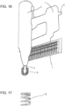
- the nail tip guide tool 8 of the present invention can be easily mounted to various nailing machines by screwing ( Fig. 16 ), as is clear from the sectional view of Fig. 3 , and also when mounting the metal reinforcing hardware 19 as a mounting material for reinforcing a structure that is often used in construction, it is possible to easily and efficiently perform work by using the guide piece type ( Fig. 2 ) described above. Further, by using the nail tip guide tool (8) having the cross-sectional shape in Fig. 1 , there is obtained a convenient effect that various types of nails can be straight and correctly nailed, without bending, into a base material to which a mounting material of a generally used material capable of being nailed is nailed.
- Fig. 16 is an overall diagram showing an outline of a nailing machine, and a nailing machine 1 has a body portion 3 provided at a front portion of a grip portion 2 that is connected to an air supply source, and a piston that is operated by compressed air and a driver member (striking rod) 4 for striking are provided in the interior of the body portion 3.
- a nose portion 5 forming a passage for a nail that is driven is provided at a lower portion of the body portion 3, and a supply port for supplying the nail, which is a driven material, is provided in a side portion of the nose portion 5.
- Nails 6 are stored in a magazine 7 as an aggregate of the nails connected one by one, and when the nail is moved into the nose, in a state where the connected nails are disconnected and separated one by one, the nail is driven into a mounting material through an injection port below the nose portion.
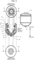
- Figs. 3 to 8 show "Example 1", and in a case where the mounting material made of a wood-based material, which is generally frequently used, is to be nailed to a base structural material or the like, a "nail tip guide tool 8" is mounted to an end portion of the nose portion 5 through a lid member 10 of a funnel-shaped container member forming the nail tip guide tool 8.
- a funnel-shaped container member 9 is joined to the lid member 10 of the funnel-shaped container member by a screw thread 26 provided at an upper end portion thereof and is mounted as the nail tip guide tool 8 by screwing it to a screw thread portion 11 provided at an outer peripheral portion of a lower end of the nose portion 5, as shown in Fig. 3 and the like. If the funnel-shaped container member 9 is made detachable in this manner, since it can be removed from this portion as needed, it is convenient for replacement or repair of a main body of the "nail tip guide tool", a guide piece, or the like.
- An inclined bottom surface portion 12 inclined downward is provided at a bottom portion of the funnel-shaped container member 9.
- the angle of the inclined bottom surface is approximately 45°, and the angle of the outer inclined surface is also set to 45°.
- An opening portion 13 that serves as a nail passage is provided at the central portion of the bottom portion of the funnel-shaped container member 9. The opening portion 13 is formed to be slightly larger than the diameter of a nail head.
- a nail tip guide piece 14 is placed on the funnel-shaped container member 9.
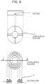
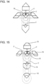
- the four guide pieces 14 each having a fan shape when viewed in plan view ( Fig. 3 ) are provided, the upper surface thereof is pressed by a torus-shaped press board 16 connected to the lid member 10 of the funnel-shaped container member through a coil spring 15, each guide piece 14 is movably supported in a state where the inclined bottom surface of the funnel-shaped container member 9 and the inclined lower end surface of the guide piece 14 are in close contact with each other, a recessed rail L ( Fig. 9 ) provided on the lower surface of the press board 16 and a protrusion portion F ( Fig. 15 ) on the upper surface of the guide piece 14 are slidably fitted to each other, and the four guide pieces are in a gathered state on the circumference.
- a mortar-shaped guide recess portion 17 is formed at the central portion of the upper surface of the aggregate of the four guide pieces that are in a gathered state on the circumference, and in the case of Example 1, at the central portion of the recess portion, a narrow round hole 24 having a diameter smaller than the shaft diameter of the nail 6 to be driven is provided to penetrate to the lower surface of the aggregate of the guide pieces 14.
- the through-hole 24 has the effect of making it easier for the tip of the nail 6 to be interposed in a case where the tip of the nail 6 driven in a tilted posture from the nose 5 slides to the center of the mortar shape along the inclined surface of the mortar shape and also has the good effect that in a case where the nail shaft or a nail head 21 tries to push and expand the four guide pieces 14 to the right and left after that, the dimension to be expanded is reduced by the dimension of the hole diameter.
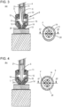
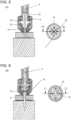
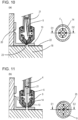
- the lower end portion of the guide piece 14 protrudes downward through the opening portion 13 of the bottom surface portion of the funnel-shaped container member. Then, a conical protrusion portion 23 of the guide piece 14 is fitted into a round hole 20 of an L-shaped reinforcing metal fitting 19 for reinforcing the mounting of a structural material 18 and positioned, and the nail 6 is driven and fixed by the nailing machine (refer to Figs. 10 to 13 ).
- the tip of the nail 6 is sharp, there is an advantage that the nail 6 can easily enter the central portion of the aggregate of the plurality of guide pieces. However, if the tip of the nail 6 is not so sharp, it does not matter. If the nail 6 continues to be pushed in by the driver member 4 in this state, the nail 6 enters the mounting material through the opening portion 13 and is driven until the flanged nail head 21 is eventually flush with the surface of the reinforcing metal fitting 19 (c of Fig. 12 ).
Landscapes
- Engineering & Computer Science (AREA)
- Mechanical Engineering (AREA)
- Physics & Mathematics (AREA)
- Fluid Mechanics (AREA)
- Chemical & Material Sciences (AREA)
- Combustion & Propulsion (AREA)
- Portable Nailing Machines And Staplers (AREA)
Claims (6)
- Nagelspitzenführungswerkzeug einer Nagelmaschine, das verwendet wird, indem es an einem Spitzenabschnitt eines Nasenabschnitts (5) montiert ist, der einen Durchgang zum Austreiben verschiedener Nägel (6) aus einer Luftnagelmaschine (1) bildet, wobei das Nagelspitzenführungswerkzeug (8) folgende Merkmale aufweist:ein Führungsstück, das derart geformt ist, dass, wenn eine Mehrzahl von Führungsstücken (14) an einem mittleren Abschnitt einer geneigten Bodenoberfläche (12) eines trichterförmigen Behälterelements (9) zusammengefasst ist, ein mörserförmiger Aussparungsabschnitt (17) an einem mittleren Abschnitt einer oberen Oberfläche einer Ansammlung der Mehrzahl von Führungsstücken (14) gebildet ist,ein Deckelelement (10) des trichterförmigen Behälterelements (9) und das trichterförmige Behälterelement (9) sind durch Schraubengewinde (26) miteinander verbunden, die an dem Deckelelement (10) und dem trichterförmigen Behälterelement (9) vorgesehen sind,die Nagelmaschine (1) und das Nagelspitzenführungswerkzeug (8) sind durch ein Schraubengewinde (11) miteinander verbunden, das an dem Deckelelement (10) des trichterförmigen Behälterelements (9) vorgesehen ist, um einem Schraubengewinde zu entsprechen, das an einem Außenumfangsabschnitt einer Spitze des Nasenabschnitts (5) der Nagelmaschine (1) vorgesehen ist,eine Spitze eines Nagels (6), der in einer geneigten Stellung aus dem Nasenabschnitt (5) getrieben wird, ist zu einem mittleren Abschnitt des mörserförmigen Aussparungsabschnitts (17) führbar, undder Nagel (6) kann an einer Position des mittleren Abschnitts des mörserförmigen Aussparungsabschnitts (17) weiter eingedrückt werden, so dass die Mehrzahl von Führungsstücken (14) nach rechts und links gedrückt und erweitert wird und einen Nagelschaftabschnitt des getriebenen Nagels (6) ergreift und umgibt, um die Stellung des Nagels (6) zu begradigen,wobei das Nagelspitzenführungswerkzeug gekennzeichnet ist durch:einen Vorsprungsabschnitt (F), der an einem Außenumfangsabschnitt einer oberen Oberfläche des Führungsstücks (14) vorgesehen ist und in eine ausgesparte Schiene (L) eingepasst ist, die radial an einer unteren Oberfläche einer torusförmigen Pressplatte (16) vorgesehen ist,eine Schraubenfeder (15), die Dehnungselastizität aufweist, ist sowohl in eine kreisförmige Nut (Y) zum Aufnehmen der Schraubenfeder (15), die an einer oberen Oberfläche der torusförmigen Pressplatte (16) vorgesehen ist, als auch eine kreisförmige Nut (P) zum Aufnehmen der Schraubenfeder (15), die an einer unteren Oberfläche des Deckelelements (10) des trichterförmigen Behälterelements (9) vorgesehen ist, eingepasst.
- Nagelspitzenführungswerkzeug einer Nagelmaschine gemäß Anspruch 1, bei dem ein Neigungswinkel des geneigten Bodenoberflächenabschnitts (12) des trichterförmigen Behälterelements (9) ungefähr 45° beträgt und die Anzahl der Mehrzahl von Führungsstücken (14) 3 beträgt.
- Nagelspitzenführungswerkzeug einer Nagelmaschine gemäß Anspruch 1 oder 2, bei dem ein Durchgangsloch (24), das einen Durchmesser aufweist, der kleiner als ein Schaftdurchmesser des zu verwendenden Nagels (6) ist, von einem Bodenabschnitt einer Mitte des mörserförmigen Aussparungsabschnitts (17), der durch Zusammenfassen der Mehrzahl von Führungsstücken (14) gebildet ist, in Richtung des mittleren Abschnitts zu unteren Endabschnitten der Mehrzahl von Führungsstücken (14) vorgesehen ist.
- Nagelspitzenführungswerkzeug einer Nagelmaschine gemäß einem der Ansprüche 1 bis 3, bei dem in einem Zustand, in dem die Führungsstücke (14) in einer Mitte zusammengefasst sind, untere Endabschnitte der zusammengefassten Führungsstücke (14) eine konische Form bilden und ein konischer Abschnitt (23) von einem unteren Endabschnitt des trichterförmigen Behälterelements (9) vorsteht.
- Nagelspitzenführungswerkzeug einer Nagelmaschine gemäß einem der Ansprüche 1 bis 3, bei dem in einem Zustand, in dem die Führungsstücke (14) in einer Mitte zusammengefasst sind, untere Endabschnitte der zusammengefassten Führungsstücke (14) auf einer gleichen Ebene wie oder höher als ein unterer Endabschnitt des trichterförmigen Behälterelements (9) angeordnet sind.
- Nagelmaschine (1) mit einem Nagelspitzenführungswerkzeug (8), bei der das Nagelspitzenführungswerkzeug (8) gemäß einem der Ansprüche 1 bis 5 an einem Nasenabschnitt einer Luftnagelmaschine montiert ist, wobei die Nagelmaschine (1) und das Nagelspitzenführungswerkzeug (8) durch ein Schraubengewinde (11) miteinander verbunden sind, das an dem Deckelelement (10) des trichterförmigen Behälterelements (9) vorgesehen ist, um einem Schraubengewinde zu entsprechen, das an einem Außenumfangsabschnitt einer Spitze des Nasenabschnitts (5) der Nagelmaschine (1) vorgesehen ist.
Applications Claiming Priority (2)
| Application Number | Priority Date | Filing Date | Title |
|---|---|---|---|
| JP2020032346 | 2020-02-08 | ||
| PCT/JP2021/005387 WO2021157747A1 (ja) | 2020-02-08 | 2021-02-05 | 釘打ち機用の釘先ガイド具 |
Publications (3)
| Publication Number | Publication Date |
|---|---|
| EP4101593A1 EP4101593A1 (de) | 2022-12-14 |
| EP4101593A4 EP4101593A4 (de) | 2024-05-01 |
| EP4101593B1 true EP4101593B1 (de) | 2025-07-09 |
Family
ID=77200684
Family Applications (1)
| Application Number | Title | Priority Date | Filing Date |
|---|---|---|---|
| EP21751417.3A Active EP4101593B1 (de) | 2020-02-08 | 2021-02-05 | Nagelspitzenführungswerkzeug für nagelmaschine |
Country Status (5)
| Country | Link |
|---|---|
| US (1) | US12023791B2 (de) |
| EP (1) | EP4101593B1 (de) |
| JP (1) | JP7316503B2 (de) |
| CN (1) | CN115379928B (de) |
| WO (1) | WO2021157747A1 (de) |
Families Citing this family (1)
| Publication number | Priority date | Publication date | Assignee | Title |
|---|---|---|---|---|
| DE102023135936A1 (de) * | 2023-12-20 | 2025-06-26 | Peri Se | Nagelführung und Nagelsystem |
Family Cites Families (15)
| Publication number | Priority date | Publication date | Assignee | Title |
|---|---|---|---|---|
| JPS4834981U (de) | 1971-08-26 | 1973-04-26 | ||
| JPS5179783U (de) | 1974-12-20 | 1976-06-24 | ||
| GB1603826A (en) * | 1977-05-20 | 1981-12-02 | Fisco Products Ltd | Nozzle assmbly for a nail guilding tool |
| CH683679A5 (de) * | 1991-08-14 | 1994-04-29 | Aerosmith Ag | Führungsvorrichtung an Nagelgeräten. |
| JPH06339874A (ja) | 1993-04-09 | 1994-12-13 | Hitachi Koki Co Ltd | 打込機 |
| JP3655173B2 (ja) | 2000-06-29 | 2005-06-02 | 株式会社マキタ | 釘打機 |
| JP3901506B2 (ja) * | 2001-12-20 | 2007-04-04 | マックス株式会社 | 釘打機における打ち込みガイド装置 |
| US6789718B2 (en) | 2002-09-17 | 2004-09-14 | Stanley Fastening Systems, L.P. | Nail placement device |
| JP4348995B2 (ja) | 2003-05-08 | 2009-10-21 | マックス株式会社 | 釘打機における釘の打出し案内機構 |
| JP4877470B2 (ja) * | 2005-09-22 | 2012-02-15 | マックス株式会社 | ガス燃焼式打込み工具のコンタクト打ち防止機構 |
| JP5055775B2 (ja) * | 2006-02-03 | 2012-10-24 | マックス株式会社 | 釘打機 |
| JP5340812B2 (ja) | 2009-06-05 | 2013-11-13 | 株式会社マキタ | 打ち込み工具 |
| DE202011000093U1 (de) * | 2010-01-15 | 2011-06-01 | Chervon Ltd., Hong Kong | Schnellspannmechanismus für elektrischen Hammer |
| CN203510371U (zh) * | 2013-10-11 | 2014-04-02 | 夏则荣 | 一种木托盘打钉装置 |
| CN209615789U (zh) * | 2018-11-02 | 2019-11-12 | 黄国达 | 一种防偏自动送钉机构 |
-
2021
- 2021-02-05 JP JP2021576212A patent/JP7316503B2/ja active Active
- 2021-02-05 EP EP21751417.3A patent/EP4101593B1/de active Active
- 2021-02-05 US US17/796,964 patent/US12023791B2/en active Active
- 2021-02-05 CN CN202180026918.1A patent/CN115379928B/zh active Active
- 2021-02-05 WO PCT/JP2021/005387 patent/WO2021157747A1/ja not_active Ceased
Also Published As
| Publication number | Publication date |
|---|---|
| JP7316503B2 (ja) | 2023-07-28 |
| WO2021157747A1 (ja) | 2021-08-12 |
| US12023791B2 (en) | 2024-07-02 |
| CN115379928A (zh) | 2022-11-22 |
| CN115379928B (zh) | 2025-01-21 |
| EP4101593A4 (de) | 2024-05-01 |
| US20230056376A1 (en) | 2023-02-23 |
| JPWO2021157747A1 (de) | 2021-08-12 |
| EP4101593A1 (de) | 2022-12-14 |
Similar Documents
| Publication | Publication Date | Title |
|---|---|---|
| US20070130757A1 (en) | Multiple connector compression tool and method | |
| US6481612B1 (en) | Fastening device delivery tool with perpendicular ram driven by a repeatable arcuate force member | |
| EP4101593B1 (de) | Nagelspitzenführungswerkzeug für nagelmaschine | |
| US6641021B2 (en) | Magazine rail system for fastener-driving tool | |
| JP2002066950A5 (de) | ||
| US20070278276A1 (en) | Nailing Tool with Displacable Discharge Tube | |
| EP1951479A1 (de) | Mehrfach-schlag-drucklufthandwerkzeug zum einsetzen von t-muttern | |
| JP5612798B1 (ja) | 釘打設補助具 | |
| EP1623798B1 (de) | Nagelmaschine | |
| TW592909B (en) | Punching guide device in nailing machine | |
| JP5218330B2 (ja) | 衝撃工具 | |
| EP0065952B1 (de) | Anordnung an geräten zum mechanischen nageln | |
| JP2007168007A (ja) | フロア施工用釘打機 | |
| JPS6216290Y2 (de) | ||
| JP2002283253A (ja) | 釘打機 | |
| JPH075985Y2 (ja) | 釘打ち機 | |
| JPH0546851Y2 (de) | ||
| JP2016078200A (ja) | 打ち込み工具 | |
| KR100866634B1 (ko) | 타카핀의 휨 방지구조를 갖는 타카장치의 블레이드 | |
| JPH04125575U (ja) | 釘打機における釘の案内装置 | |
| JPS5821661Y2 (ja) | 自動釘打機の打込ガイド | |
| JPH0633677U (ja) | ファスナ引抜き機 | |
| JP3558878B2 (ja) | 釘打機 | |
| JP2018199188A (ja) | 有頭部品の供給組立装置 | |
| JPH04300170A (ja) | 自動釘打機 |
Legal Events
| Date | Code | Title | Description |
|---|---|---|---|
| STAA | Information on the status of an ep patent application or granted ep patent |
Free format text: STATUS: THE INTERNATIONAL PUBLICATION HAS BEEN MADE |
|
| PUAI | Public reference made under article 153(3) epc to a published international application that has entered the european phase |
Free format text: ORIGINAL CODE: 0009012 |
|
| STAA | Information on the status of an ep patent application or granted ep patent |
Free format text: STATUS: REQUEST FOR EXAMINATION WAS MADE |
|
| 17P | Request for examination filed |
Effective date: 20220805 |
|
| AK | Designated contracting states |
Kind code of ref document: A1 Designated state(s): AL AT BE BG CH CY CZ DE DK EE ES FI FR GB GR HR HU IE IS IT LI LT LU LV MC MK MT NL NO PL PT RO RS SE SI SK SM TR |
|
| DAV | Request for validation of the european patent (deleted) | ||
| DAX | Request for extension of the european patent (deleted) | ||
| A4 | Supplementary search report drawn up and despatched |
Effective date: 20240403 |
|
| RIC1 | Information provided on ipc code assigned before grant |
Ipc: B25C 1/18 20060101ALI20240326BHEP Ipc: B25C 1/04 20060101ALI20240326BHEP Ipc: B25C 7/00 20060101AFI20240326BHEP |
|
| RIC1 | Information provided on ipc code assigned before grant |
Ipc: B25C 1/18 20060101ALI20241211BHEP Ipc: B25C 1/04 20060101ALI20241211BHEP Ipc: B25C 7/00 20060101AFI20241211BHEP |
|
| GRAP | Despatch of communication of intention to grant a patent |
Free format text: ORIGINAL CODE: EPIDOSNIGR1 |
|
| STAA | Information on the status of an ep patent application or granted ep patent |
Free format text: STATUS: GRANT OF PATENT IS INTENDED |
|
| INTG | Intention to grant announced |
Effective date: 20250117 |
|
| GRAS | Grant fee paid |
Free format text: ORIGINAL CODE: EPIDOSNIGR3 |
|
| GRAA | (expected) grant |
Free format text: ORIGINAL CODE: 0009210 |
|
| STAA | Information on the status of an ep patent application or granted ep patent |
Free format text: STATUS: THE PATENT HAS BEEN GRANTED |
|
| AK | Designated contracting states |
Kind code of ref document: B1 Designated state(s): AL AT BE BG CH CY CZ DE DK EE ES FI FR GB GR HR HU IE IS IT LI LT LU LV MC MK MT NL NO PL PT RO RS SE SI SK SM TR |
|
| REG | Reference to a national code |
Ref country code: GB Ref legal event code: FG4D |
|
| REG | Reference to a national code |
Ref country code: CH Ref legal event code: EP |
|
| REG | Reference to a national code |
Ref country code: IE Ref legal event code: FG4D |
|
| REG | Reference to a national code |
Ref country code: DE Ref legal event code: R096 Ref document number: 602021033817 Country of ref document: DE |
|
| REG | Reference to a national code |
Ref country code: NL Ref legal event code: MP Effective date: 20250709 |
|
| PG25 | Lapsed in a contracting state [announced via postgrant information from national office to epo] |
Ref country code: PT Free format text: LAPSE BECAUSE OF FAILURE TO SUBMIT A TRANSLATION OF THE DESCRIPTION OR TO PAY THE FEE WITHIN THE PRESCRIBED TIME-LIMIT Effective date: 20251110 |
|
| PG25 | Lapsed in a contracting state [announced via postgrant information from national office to epo] |
Ref country code: NL Free format text: LAPSE BECAUSE OF FAILURE TO SUBMIT A TRANSLATION OF THE DESCRIPTION OR TO PAY THE FEE WITHIN THE PRESCRIBED TIME-LIMIT Effective date: 20250709 |
|
| REG | Reference to a national code |
Ref country code: AT Ref legal event code: MK05 Ref document number: 1811425 Country of ref document: AT Kind code of ref document: T Effective date: 20250709 |
|
| PG25 | Lapsed in a contracting state [announced via postgrant information from national office to epo] |
Ref country code: IS Free format text: LAPSE BECAUSE OF FAILURE TO SUBMIT A TRANSLATION OF THE DESCRIPTION OR TO PAY THE FEE WITHIN THE PRESCRIBED TIME-LIMIT Effective date: 20251109 |
|
| PG25 | Lapsed in a contracting state [announced via postgrant information from national office to epo] |
Ref country code: NO Free format text: LAPSE BECAUSE OF FAILURE TO SUBMIT A TRANSLATION OF THE DESCRIPTION OR TO PAY THE FEE WITHIN THE PRESCRIBED TIME-LIMIT Effective date: 20251009 |
|
| REG | Reference to a national code |
Ref country code: LT Ref legal event code: MG9D |
|
| PG25 | Lapsed in a contracting state [announced via postgrant information from national office to epo] |
Ref country code: AT Free format text: LAPSE BECAUSE OF FAILURE TO SUBMIT A TRANSLATION OF THE DESCRIPTION OR TO PAY THE FEE WITHIN THE PRESCRIBED TIME-LIMIT Effective date: 20250709 |
|
| PG25 | Lapsed in a contracting state [announced via postgrant information from national office to epo] |
Ref country code: FI Free format text: LAPSE BECAUSE OF FAILURE TO SUBMIT A TRANSLATION OF THE DESCRIPTION OR TO PAY THE FEE WITHIN THE PRESCRIBED TIME-LIMIT Effective date: 20250709 |
|
| PG25 | Lapsed in a contracting state [announced via postgrant information from national office to epo] |
Ref country code: HR Free format text: LAPSE BECAUSE OF FAILURE TO SUBMIT A TRANSLATION OF THE DESCRIPTION OR TO PAY THE FEE WITHIN THE PRESCRIBED TIME-LIMIT Effective date: 20250709 |
|
| PG25 | Lapsed in a contracting state [announced via postgrant information from national office to epo] |
Ref country code: GR Free format text: LAPSE BECAUSE OF FAILURE TO SUBMIT A TRANSLATION OF THE DESCRIPTION OR TO PAY THE FEE WITHIN THE PRESCRIBED TIME-LIMIT Effective date: 20251010 |
|
| PG25 | Lapsed in a contracting state [announced via postgrant information from national office to epo] |
Ref country code: SE Free format text: LAPSE BECAUSE OF FAILURE TO SUBMIT A TRANSLATION OF THE DESCRIPTION OR TO PAY THE FEE WITHIN THE PRESCRIBED TIME-LIMIT Effective date: 20250709 |
|
| PG25 | Lapsed in a contracting state [announced via postgrant information from national office to epo] |
Ref country code: LV Free format text: LAPSE BECAUSE OF FAILURE TO SUBMIT A TRANSLATION OF THE DESCRIPTION OR TO PAY THE FEE WITHIN THE PRESCRIBED TIME-LIMIT Effective date: 20250709 |
|
| PG25 | Lapsed in a contracting state [announced via postgrant information from national office to epo] |
Ref country code: BG Free format text: LAPSE BECAUSE OF FAILURE TO SUBMIT A TRANSLATION OF THE DESCRIPTION OR TO PAY THE FEE WITHIN THE PRESCRIBED TIME-LIMIT Effective date: 20250709 Ref country code: PL Free format text: LAPSE BECAUSE OF FAILURE TO SUBMIT A TRANSLATION OF THE DESCRIPTION OR TO PAY THE FEE WITHIN THE PRESCRIBED TIME-LIMIT Effective date: 20250709 |
|
| PG25 | Lapsed in a contracting state [announced via postgrant information from national office to epo] |
Ref country code: RS Free format text: LAPSE BECAUSE OF FAILURE TO SUBMIT A TRANSLATION OF THE DESCRIPTION OR TO PAY THE FEE WITHIN THE PRESCRIBED TIME-LIMIT Effective date: 20251009 |
|
| PG25 | Lapsed in a contracting state [announced via postgrant information from national office to epo] |
Ref country code: ES Free format text: LAPSE BECAUSE OF FAILURE TO SUBMIT A TRANSLATION OF THE DESCRIPTION OR TO PAY THE FEE WITHIN THE PRESCRIBED TIME-LIMIT Effective date: 20250709 |
|
| PG25 | Lapsed in a contracting state [announced via postgrant information from national office to epo] |
Ref country code: SM Free format text: LAPSE BECAUSE OF FAILURE TO SUBMIT A TRANSLATION OF THE DESCRIPTION OR TO PAY THE FEE WITHIN THE PRESCRIBED TIME-LIMIT Effective date: 20250709 |
|
| PG25 | Lapsed in a contracting state [announced via postgrant information from national office to epo] |
Ref country code: DK Free format text: LAPSE BECAUSE OF FAILURE TO SUBMIT A TRANSLATION OF THE DESCRIPTION OR TO PAY THE FEE WITHIN THE PRESCRIBED TIME-LIMIT Effective date: 20250709 |
|
| PGFP | Annual fee paid to national office [announced via postgrant information from national office to epo] |
Ref country code: DE Payment date: 20260202 Year of fee payment: 6 |
|
| PGFP | Annual fee paid to national office [announced via postgrant information from national office to epo] |
Ref country code: IT Payment date: 20260227 Year of fee payment: 6 |
|
| PG25 | Lapsed in a contracting state [announced via postgrant information from national office to epo] |
Ref country code: CZ Free format text: LAPSE BECAUSE OF FAILURE TO SUBMIT A TRANSLATION OF THE DESCRIPTION OR TO PAY THE FEE WITHIN THE PRESCRIBED TIME-LIMIT Effective date: 20250709 |
|
| PG25 | Lapsed in a contracting state [announced via postgrant information from national office to epo] |
Ref country code: SK Free format text: LAPSE BECAUSE OF FAILURE TO SUBMIT A TRANSLATION OF THE DESCRIPTION OR TO PAY THE FEE WITHIN THE PRESCRIBED TIME-LIMIT Effective date: 20250709 Ref country code: EE Free format text: LAPSE BECAUSE OF FAILURE TO SUBMIT A TRANSLATION OF THE DESCRIPTION OR TO PAY THE FEE WITHIN THE PRESCRIBED TIME-LIMIT Effective date: 20250709 |