EP4101712B1 - Dispositif de commande de véhicule, support d'informations non transitoire et système de commande de véhicule - Google Patents
Dispositif de commande de véhicule, support d'informations non transitoire et système de commande de véhicule Download PDFInfo
- Publication number
- EP4101712B1 EP4101712B1 EP22176685.0A EP22176685A EP4101712B1 EP 4101712 B1 EP4101712 B1 EP 4101712B1 EP 22176685 A EP22176685 A EP 22176685A EP 4101712 B1 EP4101712 B1 EP 4101712B1
- Authority
- EP
- European Patent Office
- Prior art keywords
- vehicle
- zone
- geofencing
- motor
- drive
- Prior art date
- Legal status (The legal status is an assumption and is not a legal conclusion. Google has not performed a legal analysis and makes no representation as to the accuracy of the status listed.)
- Active
Links
Images


Classifications
-
- B—PERFORMING OPERATIONS; TRANSPORTING
- B60—VEHICLES IN GENERAL
- B60W—CONJOINT CONTROL OF VEHICLE SUB-UNITS OF DIFFERENT TYPE OR DIFFERENT FUNCTION; CONTROL SYSTEMS SPECIALLY ADAPTED FOR HYBRID VEHICLES; ROAD VEHICLE DRIVE CONTROL SYSTEMS FOR PURPOSES NOT RELATED TO THE CONTROL OF A PARTICULAR SUB-UNIT
- B60W20/00—Control systems specially adapted for hybrid vehicles
- B60W20/40—Controlling the engagement or disengagement of prime movers, e.g. for transition between prime movers
-
- B—PERFORMING OPERATIONS; TRANSPORTING
- B60—VEHICLES IN GENERAL
- B60W—CONJOINT CONTROL OF VEHICLE SUB-UNITS OF DIFFERENT TYPE OR DIFFERENT FUNCTION; CONTROL SYSTEMS SPECIALLY ADAPTED FOR HYBRID VEHICLES; ROAD VEHICLE DRIVE CONTROL SYSTEMS FOR PURPOSES NOT RELATED TO THE CONTROL OF A PARTICULAR SUB-UNIT
- B60W40/00—Estimation or calculation of non-directly measurable driving parameters for road vehicle drive control systems not related to the control of a particular sub unit, e.g. by using mathematical models
- B60W40/02—Estimation or calculation of non-directly measurable driving parameters for road vehicle drive control systems not related to the control of a particular sub unit, e.g. by using mathematical models related to ambient conditions
- B60W40/06—Road conditions
- B60W40/068—Road friction coefficient
-
- B—PERFORMING OPERATIONS; TRANSPORTING
- B60—VEHICLES IN GENERAL
- B60W—CONJOINT CONTROL OF VEHICLE SUB-UNITS OF DIFFERENT TYPE OR DIFFERENT FUNCTION; CONTROL SYSTEMS SPECIALLY ADAPTED FOR HYBRID VEHICLES; ROAD VEHICLE DRIVE CONTROL SYSTEMS FOR PURPOSES NOT RELATED TO THE CONTROL OF A PARTICULAR SUB-UNIT
- B60W10/00—Conjoint control of vehicle sub-units of different type or different function
- B60W10/04—Conjoint control of vehicle sub-units of different type or different function including control of propulsion units
- B60W10/06—Conjoint control of vehicle sub-units of different type or different function including control of propulsion units including control of combustion engines
-
- B—PERFORMING OPERATIONS; TRANSPORTING
- B60—VEHICLES IN GENERAL
- B60W—CONJOINT CONTROL OF VEHICLE SUB-UNITS OF DIFFERENT TYPE OR DIFFERENT FUNCTION; CONTROL SYSTEMS SPECIALLY ADAPTED FOR HYBRID VEHICLES; ROAD VEHICLE DRIVE CONTROL SYSTEMS FOR PURPOSES NOT RELATED TO THE CONTROL OF A PARTICULAR SUB-UNIT
- B60W10/00—Conjoint control of vehicle sub-units of different type or different function
- B60W10/04—Conjoint control of vehicle sub-units of different type or different function including control of propulsion units
- B60W10/08—Conjoint control of vehicle sub-units of different type or different function including control of propulsion units including control of electric propulsion units, e.g. motors or generators
-
- B—PERFORMING OPERATIONS; TRANSPORTING
- B60—VEHICLES IN GENERAL
- B60W—CONJOINT CONTROL OF VEHICLE SUB-UNITS OF DIFFERENT TYPE OR DIFFERENT FUNCTION; CONTROL SYSTEMS SPECIALLY ADAPTED FOR HYBRID VEHICLES; ROAD VEHICLE DRIVE CONTROL SYSTEMS FOR PURPOSES NOT RELATED TO THE CONTROL OF A PARTICULAR SUB-UNIT
- B60W20/00—Control systems specially adapted for hybrid vehicles
- B60W20/10—Controlling the power contribution of each of the prime movers to meet required power demand
- B60W20/12—Controlling the power contribution of each of the prime movers to meet required power demand using control strategies taking into account route information
-
- B—PERFORMING OPERATIONS; TRANSPORTING
- B60—VEHICLES IN GENERAL
- B60W—CONJOINT CONTROL OF VEHICLE SUB-UNITS OF DIFFERENT TYPE OR DIFFERENT FUNCTION; CONTROL SYSTEMS SPECIALLY ADAPTED FOR HYBRID VEHICLES; ROAD VEHICLE DRIVE CONTROL SYSTEMS FOR PURPOSES NOT RELATED TO THE CONTROL OF A PARTICULAR SUB-UNIT
- B60W30/00—Purposes of road vehicle drive control systems not related to the control of a particular sub-unit, e.g. of systems using conjoint control of vehicle sub-units
- B60W30/02—Control of vehicle driving stability
-
- B—PERFORMING OPERATIONS; TRANSPORTING
- B60—VEHICLES IN GENERAL
- B60W—CONJOINT CONTROL OF VEHICLE SUB-UNITS OF DIFFERENT TYPE OR DIFFERENT FUNCTION; CONTROL SYSTEMS SPECIALLY ADAPTED FOR HYBRID VEHICLES; ROAD VEHICLE DRIVE CONTROL SYSTEMS FOR PURPOSES NOT RELATED TO THE CONTROL OF A PARTICULAR SUB-UNIT
- B60W30/00—Purposes of road vehicle drive control systems not related to the control of a particular sub-unit, e.g. of systems using conjoint control of vehicle sub-units
- B60W30/18—Propelling the vehicle
- B60W30/18172—Preventing, or responsive to skidding of wheels
-
- B—PERFORMING OPERATIONS; TRANSPORTING
- B60—VEHICLES IN GENERAL
- B60W—CONJOINT CONTROL OF VEHICLE SUB-UNITS OF DIFFERENT TYPE OR DIFFERENT FUNCTION; CONTROL SYSTEMS SPECIALLY ADAPTED FOR HYBRID VEHICLES; ROAD VEHICLE DRIVE CONTROL SYSTEMS FOR PURPOSES NOT RELATED TO THE CONTROL OF A PARTICULAR SUB-UNIT
- B60W40/00—Estimation or calculation of non-directly measurable driving parameters for road vehicle drive control systems not related to the control of a particular sub unit, e.g. by using mathematical models
- B60W40/02—Estimation or calculation of non-directly measurable driving parameters for road vehicle drive control systems not related to the control of a particular sub unit, e.g. by using mathematical models related to ambient conditions
- B60W40/06—Road conditions
- B60W40/064—Degree of grip
-
- B—PERFORMING OPERATIONS; TRANSPORTING
- B60—VEHICLES IN GENERAL
- B60W—CONJOINT CONTROL OF VEHICLE SUB-UNITS OF DIFFERENT TYPE OR DIFFERENT FUNCTION; CONTROL SYSTEMS SPECIALLY ADAPTED FOR HYBRID VEHICLES; ROAD VEHICLE DRIVE CONTROL SYSTEMS FOR PURPOSES NOT RELATED TO THE CONTROL OF A PARTICULAR SUB-UNIT
- B60W50/00—Details of control systems for road vehicle drive control not related to the control of a particular sub-unit, e.g. process diagnostic or vehicle driver interfaces
- B60W50/08—Interaction between the driver and the control system
- B60W50/082—Selecting or switching between different modes of propelling
-
- H—ELECTRICITY
- H04—ELECTRIC COMMUNICATION TECHNIQUE
- H04W—WIRELESS COMMUNICATION NETWORKS
- H04W4/00—Services specially adapted for wireless communication networks; Facilities therefor
- H04W4/02—Services making use of location information
- H04W4/021—Services related to particular areas, e.g. point of interest [POI] services, venue services or geofences
-
- B—PERFORMING OPERATIONS; TRANSPORTING
- B60—VEHICLES IN GENERAL
- B60W—CONJOINT CONTROL OF VEHICLE SUB-UNITS OF DIFFERENT TYPE OR DIFFERENT FUNCTION; CONTROL SYSTEMS SPECIALLY ADAPTED FOR HYBRID VEHICLES; ROAD VEHICLE DRIVE CONTROL SYSTEMS FOR PURPOSES NOT RELATED TO THE CONTROL OF A PARTICULAR SUB-UNIT
- B60W2520/00—Input parameters relating to overall vehicle dynamics
- B60W2520/26—Wheel slip
-
- B—PERFORMING OPERATIONS; TRANSPORTING
- B60—VEHICLES IN GENERAL
- B60W—CONJOINT CONTROL OF VEHICLE SUB-UNITS OF DIFFERENT TYPE OR DIFFERENT FUNCTION; CONTROL SYSTEMS SPECIALLY ADAPTED FOR HYBRID VEHICLES; ROAD VEHICLE DRIVE CONTROL SYSTEMS FOR PURPOSES NOT RELATED TO THE CONTROL OF A PARTICULAR SUB-UNIT
- B60W2552/00—Input parameters relating to infrastructure
- B60W2552/40—Coefficient of friction
-
- B—PERFORMING OPERATIONS; TRANSPORTING
- B60—VEHICLES IN GENERAL
- B60W—CONJOINT CONTROL OF VEHICLE SUB-UNITS OF DIFFERENT TYPE OR DIFFERENT FUNCTION; CONTROL SYSTEMS SPECIALLY ADAPTED FOR HYBRID VEHICLES; ROAD VEHICLE DRIVE CONTROL SYSTEMS FOR PURPOSES NOT RELATED TO THE CONTROL OF A PARTICULAR SUB-UNIT
- B60W2555/00—Input parameters relating to exterior conditions, not covered by groups B60W2552/00, B60W2554/00
- B60W2555/20—Ambient conditions, e.g. wind or rain
-
- B—PERFORMING OPERATIONS; TRANSPORTING
- B60—VEHICLES IN GENERAL
- B60W—CONJOINT CONTROL OF VEHICLE SUB-UNITS OF DIFFERENT TYPE OR DIFFERENT FUNCTION; CONTROL SYSTEMS SPECIALLY ADAPTED FOR HYBRID VEHICLES; ROAD VEHICLE DRIVE CONTROL SYSTEMS FOR PURPOSES NOT RELATED TO THE CONTROL OF A PARTICULAR SUB-UNIT
- B60W2555/00—Input parameters relating to exterior conditions, not covered by groups B60W2552/00, B60W2554/00
- B60W2555/60—Traffic rules, e.g. speed limits or right of way
-
- Y—GENERAL TAGGING OF NEW TECHNOLOGICAL DEVELOPMENTS; GENERAL TAGGING OF CROSS-SECTIONAL TECHNOLOGIES SPANNING OVER SEVERAL SECTIONS OF THE IPC; TECHNICAL SUBJECTS COVERED BY FORMER USPC CROSS-REFERENCE ART COLLECTIONS [XRACs] AND DIGESTS
- Y02—TECHNOLOGIES OR APPLICATIONS FOR MITIGATION OR ADAPTATION AGAINST CLIMATE CHANGE
- Y02T—CLIMATE CHANGE MITIGATION TECHNOLOGIES RELATED TO TRANSPORTATION
- Y02T10/00—Road transport of goods or passengers
- Y02T10/60—Other road transportation technologies with climate change mitigation effect
- Y02T10/62—Hybrid vehicles
Definitions
- the present invention relates to a vehicle control device, a non-transitory storage medium, and a vehicle control system.
- JP 7-75210 A discloses that, in order to restrain the influence of exhaust gas, the internal combustion engine of a vehicle is stopped and the vehicle travels by the power of a motor using a battery in an air pollution reduction enhanced area. As described above, it is known to set a geofencing zone that restricts the power of travel to solely the battery in order to restrain the adverse effect on the environment.
- EP 2 689 982 A1 discusses a method of operating hybrid vehicles.
- drive by the internal combustion engine is switched to drive by the motor, for example, when the vehicle moves from the outside of the zone to the inside of the zone.
- the drive mode is switched in a case where the road surface is in a slip-prone state, such as in rainy weather, there is a probability that the vehicle slips.
- the present invention provides a vehicle control device, a non-transitory storage medium, and a vehicle control system capable of restraining the slip of a vehicle when drive by an internal combustion engine is switched to drive by a motor.
- a first aspect of the present invention relates to a vehicle control device configured to control switching of a drive mode of a vehicle including an internal combustion engine and a motor.
- the vehicle control device includes a processor configured to switch, in a case where a road surface of a perimeter of a geofencing zone is a road surface on which there is a high probability that the vehicle slips, in a movement route from an outside of the geofencing zone to an inside of the geofencing zone, the drive mode of the vehicle to drive by the motor in a state in which there is a low probability that the vehicle slips, outside the geofencing zone.
- the geofencing zone is set by a virtual perimeter in which travel of the vehicle is restricted to travel by a power of the motor.
- the processor is configured to switch the drive mode of the vehicle to the drive by the motor at a position where is outside the geofencing zone and where there is a low probability that the vehicle slips.
- the processor may be configured to switch the drive mode of the vehicle to the drive by the motor at a position outside the geofencing zone and closest to the geofencing zone, out of positions where there is a low probability that the vehicle slips.
- the processor may be configured to switch the drive mode of the vehicle to the drive by the motor while the vehicle is stopped at a position outside the geofencing zone.
- the processor may be configured to control a switching position to the drive by the motor in the vehicle to a position where there is a low probability that the vehicle slips, in a case where a travel route is set in the vehicle and the travel route passes through the geofencing zone.
- the processor may be configured to determine whether or not a road surface on the travel route is the road surface on which there is the high probability that the vehicle slips, based on the travel route set in the vehicle and road surface information acquired in the vehicle.
- the road surface information may be based on at least one of an amount of rainfall, an amount of wiper operation, and road alignment.
- a second aspect of the present invention relates to a non-transitory storage medium storing instructions that are executable by a processor of a vehicle control device that is configured to control switching of a drive mode of a vehicle including an internal combustion engine and a motor, the instructions causing the processor to perform the following functions.
- the functions include switching, in a case where a road surface of a perimeter of a geofencing zone is a road surface on which there is a high probability that the vehicle slips, in a movement route from an outside of the geofencing zone to an inside of the geofencing zone, the drive mode of the vehicle to drive by the motor in a state in which there is a low probability that the vehicle slips, outside the geofencing zone.
- the geofencing zone is set by a virtual perimeter in which travel of the vehicle is restricted to travel by a power of the motor.
- the drive mode of the vehicle is switched to the drive by the motor at a position where is outside the geofencing zone and where there is a low probability that the vehicle slips.
- the drive mode of the vehicle in the switching to the drive by the motor, may be switched to the drive by the motor at a position outside the geofencing zone and closest to the geofencing zone, out of positions where there is a low probability that the vehicle slips.
- the drive mode of the vehicle may be switched to the drive by the motor while the vehicle is stopped at a position outside the geofencing zone.
- a switching position to the drive by the motor in the vehicle may be controlled to a position where there is a low probability that the vehicle slips, in a case where a travel route is set in the vehicle and the travel route passes through the geofencing zone.
- the functions may further include determining whether or not a road surface on the travel route is the road surface on which there is the high probability that the vehicle slips, based on the travel route set in the vehicle and road surface information acquired in the vehicle.
- a third aspect of the present invention relates to a vehicle control system.
- the vehicle control system includes a vehicle and a vehicle control device.
- the vehicle includes an internal combustion engine and a motor.
- the vehicle control device includes a processor.
- the processor is configured to switch, in a case where a road surface of a perimeter of a geofencing zone is a road surface on which there is a high probability that the vehicle slips, in a movement route from an outside of the geofencing zone to an inside of the geofencing zone, the drive mode of the vehicle to drive by the motor in a state in which there is a low probability that the vehicle slips, outside the geofencing zone.
- the geofencing zone is set by a virtual perimeter in which travel of the vehicle is restricted to travel by a power of the motor.
- the processor is configured to switch the drive mode of the vehicle to the drive by the motor at a position where is outside the geofencing zone and where there is a low probability that the vehicle slips.
- the processor may be configured to switch the drive mode of the vehicle to the drive by the motor at a position outside the geofencing zone and closest to the geofencing zone, out of positions where there is a low probability that the vehicle slips.
- the processor may be configured to switch the drive mode of the vehicle to the drive by the motor while the vehicle is stopped at a position outside the geofencing zone.
- the processor may be configured to control a switching position to the drive by the motor in the vehicle to a position where there is a low probability that the vehicle slips, in a case where a travel route is set in the vehicle and the travel route passes through the geofencing zone.
- the processor may be configured to determine whether or not a road surface on the travel route is the road surface on which there is the high probability that the vehicle slips, based on the travel route set in the vehicle and road surface information acquired in the vehicle.
- the road surface information may be based on at least one of an amount of rainfall, an amount of wiper operation, and road alignment.
- FIG. 1 is a diagram schematically showing a control system according to Embodiment 1.
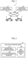
- FIG. 2 is a block diagram illustrating the configuration of a road surface information server according to Embodiment 1.
- FIG. 3 is a block diagram illustrating the configuration of a vehicle according to Embodiment 1.
- a control system 1 according to Embodiment 1 includes a road surface information server 2, a vehicle 3, and a zone setting information server 4.
- the road surface information server 2 is a server that acquires and outputs, for example, meteorological information disclosed by the Meteorological Agency or a business operator engaged in meteorological services.
- the vehicle 3 is a vehicle capable of traveling solely by the power of a motor (capable of EV traveling), such as a plug-in hybrid electric vehicle or a range extender vehicle. Further, the vehicle 3 is a vehicle capable of charging electric power from an external power source and supplying electric power to the outside.
- the road surface information server 2, the vehicle 3, and the zone setting information server 4 can perform information communication via a network NW.
- the network NW is formed of, for example, the network of the Internet or the like.
- the road surface information server 2 can transmit and receive information to and from a plurality of the vehicles 3.
- the road surface information server 2 includes a meteorological information receiver 21, a road surface information creation unit 22, and a road surface information transmitter 23.
- the meteorological information receiver 21 receives meteorological information related to the weather.
- the meteorological information includes weather for each area, rain cloud movements, and forecasts thereof.
- the road surface information creation unit 22 creates road surface information based on, for example, meteorological information.
- the road surface information is, for example, information indicating the state of the road surface for each area, and includes information indicating the high or low probability of slipping for each position of the road surface.
- the probability of slipping on the road surface can be determined based on whether or not the road surface is wet from the amount of rainfall or the amount of snowfall.
- whether or not the road surface is wet can be determined based on the amount of wiper operation of the vehicle 3 and the position information of the vehicle 3.
- whether or not the road surface is a slip-prone road surface may be determined with reference to road alignment, such as a sharp curve, or the past slip information, or can also be determined using a combination of the information.
- the road surface information transmitter 23 sends the created road surface information.
- the road surface information transmitter 23 transmits the road surface information to the vehicle 3 in the corresponding area via the network NW. Further, the road surface information transmitter 23 sends the latest road surface information every time the road surface information is updated to the latest information.
- the vehicle 3 is an electrified vehicle including a motor 11 for travel, an engine 12, a battery 13, a charger 14, a vehicle-side connector 15, and an inverter 16.
- the motor 11 is a power source for travel. Further, the engine 12 can rotate the motor 11. That is, the motor 11 can generate electric power by the power of the engine 12. In a case where the motor 11 generates electric power by the engine 12, the battery 13 can be charged with the electric power generated by the motor 11. The motor 11 is electrically connected to the battery 13 via the inverter 16.
- the vehicle 3 is a plug-in hybrid electric vehicle including the charger 14 that charges the battery 13 with electric power from the outside and the vehicle-side connector 15.
- the battery 13 is an electric power storage device that stores electric power to be supplied to the motor 11 and that also stores electric power supplied from an external power source.
- the battery 13 is conductively connected to the vehicle-side connector 15 via the charger 14.
- the charger 14 charges the battery 13 with electric power from the outside.
- the charger 14 includes various relay units.
- the relay units of the charger 14 are opened, whereby the battery 13 and the vehicle-side connector 15 can be electrically disconnected.
- the relay units of the charger 14 are closed, and the battery 13 and the vehicle-side connector 15 are electrically connected.
- the vehicle-side connector 15 can be connected to an external connector, such as a charging connector of a charging station.
- the vehicle 3 includes a global positioning system (GPS) receiver 31, a communication unit 32, a controller 33, a human machine interface (HMI) 34, a powertrain 35, and a storage unit 36.
- GPS global positioning system
- HMI human machine interface
- the GPS receiver 31 receives radio waves (signals) from GPS satellites.
- the communication unit 32 transmits and receives information to and from the zone setting information server 4.
- the communication unit 32 receives a control instruction transmitted from the zone setting information server 4. Further, the communication unit 32 transmits position information indicating the current position of the vehicle 3 to the road surface information server 2.
- the controller 33 includes a processor having hardware, such as a central processing unit (CPU), and a storage unit, such as a random access memory (RAM) and a read only memory (ROM).
- the controller 33 has a position information acquisition unit 33a, a switching controller 33b, an engine controller 33c, an HMI controller 33d, and a powertrain controller 33e.
- the position information acquisition unit 33a acquires current position information based on the signal received by the GPS receiver 31.
- the switching controller 33b controls the switching timing between an HV mode in which the vehicle 3 travels using a combination of the engine 12 and the motor 11 and an EV mode in which the vehicle 3 travels using solely the motor 11, based on the road surface information and the geofencing zone.
- the engine controller 33c controls the engine 12. For example, in a case where a drive prohibition instruction of the engine 12 is received, the engine controller 33c executes prohibition control for prohibiting the drive of the engine 12. Alternatively, in a case where a drive permission instruction of the engine 12 is received, the engine controller 33c executes permission control for permitting the drive of the engine 12.
- the HMI controller 33d controls the HMI 34.
- the HMI 34 is formed of, for example, a car navigation device.
- the HMI 34 is an in-vehicle device that functions as a notification unit which notifies a driver of information and that also functions as an operation unit which receives an operation from the driver.
- the HMI 34 notifies the driver of information such as that the vehicle 3 is in a controlled state in which the drive of the engine 12 is permitted or that the vehicle 3 is in a controlled state in which the drive of the engine 12 is prohibited, under the control of the HMI controller 33d.
- the powertrain controller 33e controls the powertrain 35.
- the powertrain 35 is a power transmission device that transmits power output from the motor 11 or the engine 12 to the drive wheels.
- the powertrain 35 includes an automatic transmission and the like. Therefore, the powertrain controller 33e executes shift control for controlling the shift stage of the automatic transmission.
- the storage unit 36 is formed using a computer-readable recording medium, and stores various programs and various data in a writable and readable manner.
- the recording medium has a storage medium, such as a hard disk, a semiconductor memory, an optical disk, a flash memory, and a magnetic disk, and a drive device for the storage medium.
- the storage unit 36 stores programs of various applications and an operating system (OS) needed for the controller 33 to control the operation of each unit of the vehicle 3 in an integrated manner.
- OS operating system
- controller 33 controls the motor 11 by controlling the inverter 16.
- switching control is performed by the controller 33. Furthermore, for the relay unit of the charger 14, open/close control is performed by the controller 33. That is, the controller 33 executes charge control for charging the battery 13 with electric power from the outside, and also executes discharge control for supplying the electric power stored in the battery 13 to the outside. Further, the controller 33 executes various control related to the vehicle 3.
- the zone setting information server 4 outputs the setting information of the geofencing zone.
- the information of the area where the geofencing zone is set is set as map information and coordinate information.
- a virtual fence (virtual perimeter) called geofencing is set in a predetermined area (geofencing zone).
- the geofencing zone is set for a specific area, such as an urban area.
- specific vehicle control is executed for the vehicle 3 located in the geofencing zone.
- the vehicle control includes drive control for prohibiting engine drive so that the vehicle travels solely by the motor (EV travel).
- FIG. 4 is a diagram illustrating the geofencing zone. For example, the drive prohibition instruction for the engine 12 is transmitted to the vehicle 3 located in the geofencing zone R G shown in FIG. 4 .
- FIG. 5 is a flowchart showing an example of vehicle control processing according to Embodiment 1. In FIG. 5 , description is made assuming that a route to enter the inside of the geofencing zone from the outside of the geofencing zone is set.
- the controller 33 determines whether or not the geofencing zone is included in the route, based on the travel route set by the HMI 34 and the position information of the geofencing zone acquired from the zone setting information server 4 (step S101).
- the controller 33 ends the HV/EV switching control in a case where the geofencing zone is not included in the route (step S101: No).
- the controller 33 proceeds to step S102 in a case where the geofencing zone is included in the route (step S101: Yes).
- step S102 the switching controller 33b determines whether or not there is a high probability of slipping on the road surface at the perimeter of the geofencing zone.
- the switching controller 33b determines whether or not there is a high probability of slipping at the perimeter between the inside of the geofencing zone and the outside of the geofencing zone, particularly a region near the perimeter including the perimeter through which the travel route passes, based on the road surface information and the geofencing zone.
- step S102 determines that there is a low probability of slipping on the road surface at the perimeter of the geofencing zone (step S102: No)
- the switching controller 33b proceeds to step S106.
- step S102 determines that there is a high probability of slipping on the road surface at the perimeter of the geofencing zone (step S102: Yes)
- the switching controller 33b proceeds to step S103.
- the switching controller 33b sets a position (HV/EV switching position) where the HV mode and the EV mode are switched.
- the switching controller 33b sets, for example, a position where there is a low probability of slipping on the road surface in the route and which is closest to the geofencing zone to the HV/EV switching position, based on the road surface information.
- the HV/EV switching position is not limited to the position on the map, and may be, for example, an intersection at the timing at which the vehicle 3 is stopped.
- step S104 determines whether or not the vehicle 3 has reached the HV/EV switching position set in step S103 (step S104).
- the controller 33 determines whether or not the vehicle 3 has reached the HV/EV switching position by referring to the position information acquired by the position information acquisition unit 33a. In a case where the controller 33 determines that the vehicle 3 has not reached the HV/EV switching position (step S104: No), the controller 33 repeats the confirmation that the vehicle 3 has reached the HV/EV switching position. On the other hand, in a case where the controller 33 determines that the vehicle 3 has reached the HV/EV switching position (step S104: Yes), the controller 33 proceeds to step S105.
- step S105 the switching controller 33b switches the HV mode to the EV mode at the HV/EV switching position.
- the HV/EV switching processing is executed at a position outside the geofencing zone and closest to the geofencing zone, where there is a low probability of slipping on the road surface.
- step S106 the switching controller 33b performs normal HV/EV switching.
- the switching processing from the HV mode to the EV mode is executed at the perimeter between the inside of the geofencing zone and the outside of the geofencing zone.
- Embodiment 1 described above in a case where there is a high probability of slipping on the road surface in the HV/EV switching from the outside of the geofencing zone to the inside of the geofencing zone, the HV/EV switching is performed at a position outside the geofencing zone, where there is a low probability of slipping on the road surface. According to Embodiment 1, since the HV/EV switching is executed at a position where the road surface is not wet, it is possible to restrain the slip of the vehicle caused by the change in torque when the drive by the internal combustion engine (engine 12) is switched to the drive by the motor (motor 11).
- FIG. 6 is a diagram schematically showing a control system according to Embodiment 2.
- FIG. 7 is a block diagram illustrating the configuration of the control system according to Embodiment 2.
- a control system 1A according to Embodiment 2 includes a vehicle 3A instead of the vehicle 3 with respect to the configuration of the control system 1 according to Embodiment 1, and further includes a vehicle management server 5.
- parts different from Embodiment 1 (configurations and processing contents of the vehicle 3A and the vehicle management server 5) will be described.
- the control system 1A includes the road surface information server 2, the vehicle 3A, the zone setting information server 4, and the vehicle management server 5.
- the vehicle 3A has a configuration in which a controller 33A having no switching controller 33b is provided, with respect to the configuration of the vehicle 3.
- the vehicle management server 5 is a server installed in a vehicle management center.
- the vehicle management center monitors the position information of the vehicle 3A in real time, for a plurality of vehicles 3A.
- the road surface information server 2 and the vehicle management server 5 can perform information communication via the network NW.
- the network NW is formed of, for example, the network of the Internet or the like. Further, the vehicle 3A and the vehicle management server 5 can perform wireless communication via the network NW.
- the vehicle management server 5 includes a position information receiver 51, a road surface information receiver 52, a storage unit 53, a controller 54, and an instruction transmitter 55.
- the position information receiver 51 receives current position information transmitted from the vehicle 3A.
- the vehicle management server 5 can receive the position information of the vehicle 3A transmitted from each of the vehicles 3A by the position information receiver 51.
- the road surface information receiver 52 receives disaster area information transmitted from the road surface information server 2.
- the road surface information receiver 52 can communicate with the road surface information transmitter 23 via the network NW.
- the storage unit 53 stores various information for managing the vehicle 3A.
- the storage unit 53 stores information regarding an area in which a geofencing zone is set.
- the geofencing information is pre-stored information.
- the storage unit 53 has a position information database 53a.
- the position information database 53a stores the position information of the vehicle 3A.
- the position information regarding the vehicles 3A is stored in the position information database 53a in real time, based on the position information received by the position information receiver 51. That is, the position information stored in the position information database 53a is updated to the latest position information at any time.
- the controller 54 includes a processor having hardware, such as a CPU. Further, the controller 54 has a switching controller 54a.
- the controller 54 specifies the vehicle 3A located in the geofencing zone. For example, the controller 54 specifies the vehicle 3A located in the geofencing zone based on the geofencing information stored in the storage unit 36 and the position information stored in the position information database 53a. The controller 54 executes specific vehicle control (control program) for the specified vehicle 3A.
- the instruction transmitter 55 transmits a control instruction for executing the specific vehicle control to the vehicle 3A.
- Examples of the control instruction for a target vehicle includes an instruction for prohibiting the drive of the engine 12 inside the geofencing zone (engine drive prohibition instruction) or an instruction for permitting the drive of the engine 12 outside the geofencing zone (engine drive permission instruction), and HV/EV switching control.
- the vehicle management server 5 acquires road surface information from the road surface information server 2, and the switching controller 54a performs the timing control of HV/EV switching for the vehicle 3A located inside or outside the geofencing zone. Specifically, the switching controller 54a executes the processing shown in FIG. 5 for each vehicle 3A, and outputs an HV/EV switching instruction to each vehicle 3A.
- Embodiment 2 described above in a case where there is a high probability of slipping on the road surface in the HV/EV switching from the outside of the geofencing zone to the inside of the geofencing zone, the HV/EV switching is performed at a position outside the geofencing zone, where there is low probability of slipping on the road surface. According to Embodiment 2, since the HV/EV switching is executed at a position where the road surface is not wet, it is possible to restrain the slip of the vehicle caused by the change in torque when the drive by the internal combustion engine (engine 12) is switched to the drive by the motor (motor 11).
- the switching controller 54a since the switching controller 54a collectively provides instructions of the HV/EV switching control for the vehicles 3A, it is not needed for each vehicle 3Ato execute the processing for the HV/EV switching control. Therefore, it is possible to reduce the processing load of the vehicle 3A and restrain the battery 13 of the vehicle 3A from running low.
- the road surface information server 2 can detect meteorological information based on information posted on a posting site or the like on the Internet or information sent by a public institution, such as a local government. For example, in a case where information posted on a posting site or the like on the Internet is used, the road surface information server 2 detects the information via the network NW. Specifically, a configuration may be adopted in which information indicating rainfall is detected based on a word posted on a social networking service (SNS) on the Internet or a word frequently tweeted on Twitter (registered trademark) on a certain day.
- SNS social networking service
- the HMI 34 is not limited to the car navigation device, and may be a device that functions as a notification unit capable of transmitting information by the driver's sight, hearing, or perception.
- the HMI 34 may be a voice device, such as an audio, capable of providing notification by voice, or a device that generates vibration in the driver's seat of the vehicle 3.
- a program capable of executing the processing method by the control system can be recorded on a recording medium readable by a computer or other machines or devices (hereinafter, referred to as a computer or the like).
- the program on the recording medium is read to and executed on the computer or the like, whereby the computer or the like functions as a controller of each device of the control system.
- the recording medium that is readable by the computer or the like refers to a non-transitory recording medium on which information, such as data or programs, can be accumulated by an electrical, magnetic, optical, mechanical, or chemical action and can be read through the computer or the like.
- examples of recording mediums that are removable from the computer or the like include a flexible disk, a magneto-optical disk, a CD-ROM, a CD-R/W, a digital versatile disk (DVD), a Blu-ray (registered trademark) disc (BD), a digital audio tape (DAT), a magnetic tape, and a memory card, such as a flash memory.
- Examples of recording mediums that are fixed in the computer or the like include a hard disk and a ROM.
- an SSD is available as a recording medium that is removable from the computer or the like or as a recording medium that is fixed in the computer or the like.
- a "unit” can be replaced with a “circuit” or the like.
- the communication unit can be replaced with a communication circuit.
- the program that is executed by each device of the control system may be provided by storing the program on a computer connected to a network, such as the Internet, and downloading the program by way of the network.
Landscapes
- Engineering & Computer Science (AREA)
- Transportation (AREA)
- Mechanical Engineering (AREA)
- Automation & Control Theory (AREA)
- Chemical & Material Sciences (AREA)
- Combustion & Propulsion (AREA)
- Mathematical Physics (AREA)
- Physics & Mathematics (AREA)
- Computer Networks & Wireless Communication (AREA)
- Signal Processing (AREA)
- Human Computer Interaction (AREA)
- Electric Propulsion And Braking For Vehicles (AREA)
- Hybrid Electric Vehicles (AREA)
Claims (12)
- Dispositif de commande de véhicule configuré pour commander la commutation d'un mode de conduite d'un véhicule (3 ; 3A) comportant un moteur à combustion interne et un moteur électrique (11), le dispositif de commande de véhicule étant configuré pour commuter, dans le cas où une surface routière d'un périmètre d'une zone de gardiennage virtuel est une surface routière présentant un risque élevé de dérapage du véhicule (3 ; 3A), sur un itinéraire allant de l'extérieur de la zone de gardiennage virtuel vers l'intérieur de la zone de gardiennage virtuel, le mode de conduite du véhicule (3 ; 3A) sur une conduite au moyen du moteur électrique (11) lorsqu'il y a un faible risque de dérapage du véhicule (3 ; 3A), en dehors de la zone de gardiennage virtuel, la zone de gardiennage virtuel étant définie par un périmètre virtuel dans lequel le déplacement du véhicule (3 ; 3A) est limité à un déplacement par la puissance du moteur électrique (11), le processeur étant configuré pour commuter le mode de conduite du véhicule (3 ; 3A) sur la conduite au moyen du moteur électrique (11) à une position située en dehors de la zone de gardiennage virtuel et présentant un faible risque de dérapage du véhicule (3 ; 3A).
- Dispositif de commande de véhicule selon la revendication 1, dans lequel le processeur est configuré pour commuter le mode de conduite du véhicule (3 ; 3A) sur la conduite au moyen du moteur électrique (11) à une position qui est en dehors de la zone de gardiennage virtuel et qui est la plus proche de la zone de gardiennage virtuel parmi des positions présentant le faible risque de dérapage du véhicule (3 ; 3A).
- Dispositif de commande de véhicule selon la revendication 1, dans lequel le processeur est configuré pour commuter le mode de conduite du véhicule (3 ; 3A) sur la conduite au moyen du moteur électrique (11) alors que le véhicule (3 ; 3A) est arrêté à une position qui est en dehors de la zone de gardiennage virtuel.
- Dispositif de commande de véhicule selon la revendication 1, dans lequel le processeur est configuré pour commander une position de commutation sur la conduite au moyen du moteur électrique (11) dans le véhicule (3 ; 3A) sur une position présentant le faible risque de dérapage du véhicule (3 ; 3A), dans le cas où un itinéraire est défini dans le véhicule (3 ; 3A) et où le trajet traverse la zone de gardiennage virtuel.
- Dispositif de commande de véhicule selon la revendication 4, dans lequel le processeur est configuré pour déterminer si une surface routière sur l'itinéraire correspond ou non à la surface routière présentant le risque élevé de dérapage du véhicule (3 ; 3A), sur la base de l'itinéraire défini dans le véhicule (3 ; 3A) et d'informations sur la surface routière acquises dans le véhicule (3 ; 3A).
- Dispositif de commande de véhicule selon la revendication 5, dans lequel les informations sur la surface routière sont basées sur une quantité de précipitations et/ou une fréquence de fonctionnement des essuie-glaces et/ou un tracé routier.
- Support de stockage non transitoire stockant des instructions exécutables par un processeur d'un dispositif de commande de véhicule qui est configuré pour commander la commutation d'un mode de conduite d'un véhicule (3 ; 3A) comportant un moteur à combustion interne et un moteur électrique (11), les instructions amenant le processeur à exécuter des fonctions comprenant la commutation, dans le cas où une surface routière d'un périmètre d'une zone de gardiennage virtuel est une surface routière présentant un risque élevé de dérapage du véhicule (3 ; 3A), sur un itinéraire allant de l'extérieur de la zone de gardiennage virtuel vers l'intérieur de la zone de gardiennage virtuel, du mode de conduite du véhicule (3 ; 3A) sur une conduite au moyen du moteur électrique (11) lorsqu'il y a un faible risque de dérapage du véhicule (3 ; 3A), en dehors de la zone de gardiennage virtuel, la zone de gardiennage virtuel étant définie par un périmètre virtuel dans lequel le déplacement du véhicule (3 ; 3A) est limité à un déplacement par la puissance du moteur électrique (11), lors de la commutation sur la conduite au moyen du moteur électrique (11), le mode de conduite du véhicule (3 ; 3A) étant commuté sur la conduite au moyen du moteur électrique (11) à une position située en dehors de la zone de gardiennage virtuel et présentant le faible risque de dérapage du véhicule (3 ; 3A).
- Support de stockage non transitoire selon la revendication 7, dans lequel, lors de la commutation sur la conduite au moyen du moteur électrique (11), le mode de conduite du véhicule (3 ; 3A) est commuté sur la conduite au moyen du moteur électrique (11) à une position qui est en dehors de la zone de gardiennage virtuel et qui est la plus proche de la zone de gardiennage virtuel parmi des positions présentant le faible risque de dérapage du véhicule (3 ; 3A).
- Support de stockage non transitoire selon la revendication 7, dans lequel, lors de la commutation sur la conduite au moyen du moteur électrique (11), le mode de conduite du véhicule (3 ; 3A) est commuté sur la conduite au moyen du moteur électrique (11) alors que le véhicule (3 ; 3A) est arrêté à une position qui est en dehors de la zone de gardiennage virtuel.
- Support de stockage non transitoire selon la revendication 7, dans lequel, lors de la commutation sur la conduite au moyen du moteur électrique (11), une position de commutation sur la conduite au moyen du moteur électrique (11) dans le véhicule (3 ; 3A) est commandée sur une position présentant le faible risque de dérapage du véhicule (3 ; 3A), dans le cas où un itinéraire est défini dans le véhicule (3 ; 3A) et où l'itinéraire traverse la zone de gardiennage virtuel.
- Support de stockage non transitoire selon la revendication 10, dans lequel les fonctions comprennent en outre la détermination si une surface routière sur l'itinéraire correspond ou non à la surface routière présentant le risque élevé de dérapage du véhicule (3 ; 3A), sur la base de l'itinéraire défini dans le véhicule (3 ; 3A) et d'informations sur la surface routière acquises dans le véhicule (3 ; 3A).
- Système de commande de véhicule, comprenant :un véhicule (3 ; 3A) comportant un moteur à combustion interne et un moteur électrique (11) ; etun dispositif de commande de véhicule selon l'une quelconque des revendications 1 à 6.
Applications Claiming Priority (1)
| Application Number | Priority Date | Filing Date | Title |
|---|---|---|---|
| JP2021095350A JP2022187356A (ja) | 2021-06-07 | 2021-06-07 | 車両制御装置、車両制御プログラム及び車両制御システム |
Publications (2)
| Publication Number | Publication Date |
|---|---|
| EP4101712A1 EP4101712A1 (fr) | 2022-12-14 |
| EP4101712B1 true EP4101712B1 (fr) | 2024-02-14 |
Family
ID=81877740
Family Applications (1)
| Application Number | Title | Priority Date | Filing Date |
|---|---|---|---|
| EP22176685.0A Active EP4101712B1 (fr) | 2021-06-07 | 2022-06-01 | Dispositif de commande de véhicule, support d'informations non transitoire et système de commande de véhicule |
Country Status (4)
| Country | Link |
|---|---|
| US (1) | US11807244B2 (fr) |
| EP (1) | EP4101712B1 (fr) |
| JP (1) | JP2022187356A (fr) |
| CN (1) | CN115503686B (fr) |
Families Citing this family (1)
| Publication number | Priority date | Publication date | Assignee | Title |
|---|---|---|---|---|
| US20250388223A1 (en) * | 2024-06-21 | 2025-12-25 | Ford Global Technologies, Llc | Systems and methods to adjust vehicle parameters in a geofenced area |
Family Cites Families (27)
| Publication number | Priority date | Publication date | Assignee | Title |
|---|---|---|---|---|
| US4702341A (en) * | 1985-12-13 | 1987-10-27 | Toyota Jidosha Kabushiki Kaisha | Four wheel drive vehicle slippage control device and method limiting center differential action according to input torque supplied thereto |
| JP3092403B2 (ja) | 1993-09-06 | 2000-09-25 | 三菱自動車工業株式会社 | ハイブリッド電気自動車 |
| JP3386530B2 (ja) * | 1993-10-04 | 2003-03-17 | 株式会社エクォス・リサーチ | ハイブリッド型車両 |
| JPH0820323A (ja) * | 1994-07-07 | 1996-01-23 | Mazda Motor Corp | 車両のアンチスキッドブレーキ装置 |
| JP4331905B2 (ja) * | 2001-09-28 | 2009-09-16 | パイオニア株式会社 | ハイブリッドカー、及びハイブリッドカーの制御方法 |
| JP3610970B2 (ja) * | 2002-08-30 | 2005-01-19 | 日産自動車株式会社 | 四輪駆動車両の駆動力制御装置 |
| EP1466775A3 (fr) * | 2003-04-10 | 2010-09-15 | Nissan Motor Company Limited | Dispositif et méthode de commande de force d'entraînement pour véhicule |
| JP2006130946A (ja) * | 2004-11-02 | 2006-05-25 | Toyota Motor Corp | 自動車および交通システム |
| JP4685655B2 (ja) * | 2006-02-15 | 2011-05-18 | トヨタ自動車株式会社 | 電動車両の制御装置 |
| EP2070788B1 (fr) * | 2006-09-28 | 2013-01-09 | Toyota Jidosha Kabushiki Kaisha | Dispositif de commande de vehicule |
| JP4915233B2 (ja) * | 2006-12-20 | 2012-04-11 | 日産自動車株式会社 | ハイブリッド車両の制御装置 |
| JP5170007B2 (ja) * | 2009-06-15 | 2013-03-27 | 株式会社デンソー | 内燃機関の自動停止始動制御装置 |
| JP5211002B2 (ja) * | 2009-09-15 | 2013-06-12 | 日立オートモティブシステムズ株式会社 | 駆動制御装置 |
| KR101447844B1 (ko) * | 2010-10-21 | 2014-10-13 | 닛산 지도우샤 가부시키가이샤 | 차량의 구동력 제어 장치 |
| JP2013052693A (ja) * | 2011-08-31 | 2013-03-21 | Aisin Aw Co Ltd | 車両制御装置、車両制御方法、及び車両制御プログラム |
| EP2689982B1 (fr) * | 2012-07-26 | 2017-11-08 | Fujitsu Limited | Procédé d'entraînement de véhicules hybrides |
| US9352737B2 (en) * | 2012-10-08 | 2016-05-31 | Ford Global Technologies, Llc | Method and system for operating a hybrid powertrain |
| JP5677406B2 (ja) * | 2012-12-26 | 2015-02-25 | 本田技研工業株式会社 | 内燃機関の自動停止始動制御装置 |
| CN104527642A (zh) * | 2014-12-31 | 2015-04-22 | 江苏大学 | 基于场景多样性识别的自动泊车系统及其方法 |
| JP6435946B2 (ja) * | 2015-03-24 | 2018-12-12 | 株式会社ジェイテクト | 四輪駆動車及び四輪駆動車の制御装置 |
| DE102017206125A1 (de) * | 2017-04-10 | 2018-10-11 | Robert Bosch Gmbh | Verfahren und Vorrichtung zum Erstellen und Bereitstellen einer Karte |
| JP6969225B2 (ja) * | 2017-08-25 | 2021-11-24 | 株式会社ジェイテクト | 4輪駆動車及び4輪駆動車の制御方法 |
| JP2019215779A (ja) * | 2018-06-14 | 2019-12-19 | ロベルト・ボッシュ・ゲゼルシャフト・ミト・ベシュレンクテル・ハフツングRobert Bosch Gmbh | 車両の走行支援システム |
| JP7135735B2 (ja) * | 2018-10-31 | 2022-09-13 | トヨタ自動車株式会社 | 通信制御装置、通信システム、通信制御装置が行う方法 |
| JP6964060B2 (ja) * | 2018-11-20 | 2021-11-10 | 本田技研工業株式会社 | 車両制御システム |
| JP2021037819A (ja) * | 2019-09-02 | 2021-03-11 | 本田技研工業株式会社 | 車両制御装置 |
| JP7440377B2 (ja) * | 2020-08-24 | 2024-02-28 | 株式会社Subaru | 車両制御システム |
-
2021
- 2021-06-07 JP JP2021095350A patent/JP2022187356A/ja active Pending
-
2022
- 2022-06-01 EP EP22176685.0A patent/EP4101712B1/fr active Active
- 2022-06-01 US US17/829,367 patent/US11807244B2/en active Active
- 2022-06-02 CN CN202210622013.7A patent/CN115503686B/zh active Active
Also Published As
| Publication number | Publication date |
|---|---|
| US11807244B2 (en) | 2023-11-07 |
| US20220388517A1 (en) | 2022-12-08 |
| CN115503686B (zh) | 2026-02-27 |
| CN115503686A (zh) | 2022-12-23 |
| EP4101712A1 (fr) | 2022-12-14 |
| JP2022187356A (ja) | 2022-12-19 |
Similar Documents
| Publication | Publication Date | Title |
|---|---|---|
| CN111984282B (zh) | 软件更新装置、服务器装置及软件更新方法 | |
| US11307043B2 (en) | Vehicle energy management | |
| US20200004269A1 (en) | Traveling assistance device, traveling assistance management device, methods of same devices, and traveling assistance system | |
| US10479297B2 (en) | Control apparatus, program updating method, and computer program | |
| US8838385B2 (en) | Method and apparatus for vehicle routing | |
| US20190263271A1 (en) | Execution of charge session swap based on charging priority | |
| CN110320904A (zh) | 控制装置、非暂时性记录介质、以及控制方法 | |
| JP2019074853A (ja) | 車載通信装置、通信制御方法、及び車両 | |
| CN114078287A (zh) | 操作具有至少一个牵引电池驱动的牵引马达的传动系的机动车辆的方法 | |
| US20190272164A1 (en) | Software management system and software management method | |
| US10507799B1 (en) | Vehicle location tracking | |
| CN114390644B (zh) | 通信控制装置、通信控制方法和非暂态性存储介质 | |
| CN114937351B (zh) | 车队控制方法、装置、存储介质、芯片、电子设备及车辆 | |
| EP4101712B1 (fr) | Dispositif de commande de véhicule, support d'informations non transitoire et système de commande de véhicule | |
| JP2019144655A (ja) | 車載装置及びプローブデータの送信方法 | |
| WO2012132014A1 (fr) | Dispositif de calcul, système de calcul, terminal et procédé de calcul | |
| JP7585994B2 (ja) | 車両制御方法 | |
| JP2024062799A (ja) | 車載装置 | |
| CN114827108A (zh) | 车辆升级方法、装置、存储介质、芯片及车辆 | |
| US11985583B2 (en) | Communication control apparatus, communication control method, and non-transitory storage medium with communicability information updating | |
| US20240210205A1 (en) | Communication device and vehicle | |
| JP7669813B2 (ja) | 充電制御装置、充電制御プログラム及び充電制御システム | |
| JP7468425B2 (ja) | ライドシェアシステム及びライドシェア方法 | |
| JP2025119994A (ja) | 給電支援装置 | |
| CN120340284A (zh) | 运行管理装置和MaaS提供方法 |
Legal Events
| Date | Code | Title | Description |
|---|---|---|---|
| PUAI | Public reference made under article 153(3) epc to a published international application that has entered the european phase |
Free format text: ORIGINAL CODE: 0009012 |
|
| STAA | Information on the status of an ep patent application or granted ep patent |
Free format text: STATUS: REQUEST FOR EXAMINATION WAS MADE |
|
| 17P | Request for examination filed |
Effective date: 20220617 |
|
| AK | Designated contracting states |
Kind code of ref document: A1 Designated state(s): AL AT BE BG CH CY CZ DE DK EE ES FI FR GB GR HR HU IE IS IT LI LT LU LV MC MK MT NL NO PL PT RO RS SE SI SK SM TR |
|
| GRAP | Despatch of communication of intention to grant a patent |
Free format text: ORIGINAL CODE: EPIDOSNIGR1 |
|
| STAA | Information on the status of an ep patent application or granted ep patent |
Free format text: STATUS: GRANT OF PATENT IS INTENDED |
|
| INTG | Intention to grant announced |
Effective date: 20230926 |
|
| GRAS | Grant fee paid |
Free format text: ORIGINAL CODE: EPIDOSNIGR3 |
|
| GRAA | (expected) grant |
Free format text: ORIGINAL CODE: 0009210 |
|
| STAA | Information on the status of an ep patent application or granted ep patent |
Free format text: STATUS: THE PATENT HAS BEEN GRANTED |
|
| AK | Designated contracting states |
Kind code of ref document: B1 Designated state(s): AL AT BE BG CH CY CZ DE DK EE ES FI FR GB GR HR HU IE IS IT LI LT LU LV MC MK MT NL NO PL PT RO RS SE SI SK SM TR |
|
| REG | Reference to a national code |
Ref country code: GB Ref legal event code: FG4D |
|
| REG | Reference to a national code |
Ref country code: CH Ref legal event code: EP |
|
| REG | Reference to a national code |
Ref country code: DE Ref legal event code: R096 Ref document number: 602022001926 Country of ref document: DE |
|
| REG | Reference to a national code |
Ref country code: IE Ref legal event code: FG4D |
|
| P01 | Opt-out of the competence of the unified patent court (upc) registered |
Effective date: 20240419 |
|
| REG | Reference to a national code |
Ref country code: LT Ref legal event code: MG9D |
|
| REG | Reference to a national code |
Ref country code: DE Ref legal event code: R084 Ref document number: 602022001926 Country of ref document: DE |
|
| REG | Reference to a national code |
Ref country code: NL Ref legal event code: MP Effective date: 20240214 |
|
| PG25 | Lapsed in a contracting state [announced via postgrant information from national office to epo] |
Ref country code: IS Free format text: LAPSE BECAUSE OF FAILURE TO SUBMIT A TRANSLATION OF THE DESCRIPTION OR TO PAY THE FEE WITHIN THE PRESCRIBED TIME-LIMIT Effective date: 20240614 |
|
| PG25 | Lapsed in a contracting state [announced via postgrant information from national office to epo] |
Ref country code: LT Free format text: LAPSE BECAUSE OF FAILURE TO SUBMIT A TRANSLATION OF THE DESCRIPTION OR TO PAY THE FEE WITHIN THE PRESCRIBED TIME-LIMIT Effective date: 20240214 |
|
| PG25 | Lapsed in a contracting state [announced via postgrant information from national office to epo] |
Ref country code: GR Free format text: LAPSE BECAUSE OF FAILURE TO SUBMIT A TRANSLATION OF THE DESCRIPTION OR TO PAY THE FEE WITHIN THE PRESCRIBED TIME-LIMIT Effective date: 20240515 |
|
| REG | Reference to a national code |
Ref country code: AT Ref legal event code: MK05 Ref document number: 1656803 Country of ref document: AT Kind code of ref document: T Effective date: 20240214 |
|
| PG25 | Lapsed in a contracting state [announced via postgrant information from national office to epo] |
Ref country code: HR Free format text: LAPSE BECAUSE OF FAILURE TO SUBMIT A TRANSLATION OF THE DESCRIPTION OR TO PAY THE FEE WITHIN THE PRESCRIBED TIME-LIMIT Effective date: 20240214 Ref country code: RS Free format text: LAPSE BECAUSE OF FAILURE TO SUBMIT A TRANSLATION OF THE DESCRIPTION OR TO PAY THE FEE WITHIN THE PRESCRIBED TIME-LIMIT Effective date: 20240514 Ref country code: NL Free format text: LAPSE BECAUSE OF FAILURE TO SUBMIT A TRANSLATION OF THE DESCRIPTION OR TO PAY THE FEE WITHIN THE PRESCRIBED TIME-LIMIT Effective date: 20240214 |
|
| PG25 | Lapsed in a contracting state [announced via postgrant information from national office to epo] |
Ref country code: ES Free format text: LAPSE BECAUSE OF FAILURE TO SUBMIT A TRANSLATION OF THE DESCRIPTION OR TO PAY THE FEE WITHIN THE PRESCRIBED TIME-LIMIT Effective date: 20240214 |
|
| PG25 | Lapsed in a contracting state [announced via postgrant information from national office to epo] |
Ref country code: AT Free format text: LAPSE BECAUSE OF FAILURE TO SUBMIT A TRANSLATION OF THE DESCRIPTION OR TO PAY THE FEE WITHIN THE PRESCRIBED TIME-LIMIT Effective date: 20240214 |
|
| PG25 | Lapsed in a contracting state [announced via postgrant information from national office to epo] |
Ref country code: RS Free format text: LAPSE BECAUSE OF FAILURE TO SUBMIT A TRANSLATION OF THE DESCRIPTION OR TO PAY THE FEE WITHIN THE PRESCRIBED TIME-LIMIT Effective date: 20240514 Ref country code: NO Free format text: LAPSE BECAUSE OF FAILURE TO SUBMIT A TRANSLATION OF THE DESCRIPTION OR TO PAY THE FEE WITHIN THE PRESCRIBED TIME-LIMIT Effective date: 20240514 Ref country code: NL Free format text: LAPSE BECAUSE OF FAILURE TO SUBMIT A TRANSLATION OF THE DESCRIPTION OR TO PAY THE FEE WITHIN THE PRESCRIBED TIME-LIMIT Effective date: 20240214 Ref country code: LT Free format text: LAPSE BECAUSE OF FAILURE TO SUBMIT A TRANSLATION OF THE DESCRIPTION OR TO PAY THE FEE WITHIN THE PRESCRIBED TIME-LIMIT Effective date: 20240214 Ref country code: IS Free format text: LAPSE BECAUSE OF FAILURE TO SUBMIT A TRANSLATION OF THE DESCRIPTION OR TO PAY THE FEE WITHIN THE PRESCRIBED TIME-LIMIT Effective date: 20240614 Ref country code: HR Free format text: LAPSE BECAUSE OF FAILURE TO SUBMIT A TRANSLATION OF THE DESCRIPTION OR TO PAY THE FEE WITHIN THE PRESCRIBED TIME-LIMIT Effective date: 20240214 Ref country code: GR Free format text: LAPSE BECAUSE OF FAILURE TO SUBMIT A TRANSLATION OF THE DESCRIPTION OR TO PAY THE FEE WITHIN THE PRESCRIBED TIME-LIMIT Effective date: 20240515 Ref country code: FI Free format text: LAPSE BECAUSE OF FAILURE TO SUBMIT A TRANSLATION OF THE DESCRIPTION OR TO PAY THE FEE WITHIN THE PRESCRIBED TIME-LIMIT Effective date: 20240214 Ref country code: ES Free format text: LAPSE BECAUSE OF FAILURE TO SUBMIT A TRANSLATION OF THE DESCRIPTION OR TO PAY THE FEE WITHIN THE PRESCRIBED TIME-LIMIT Effective date: 20240214 Ref country code: BG Free format text: LAPSE BECAUSE OF FAILURE TO SUBMIT A TRANSLATION OF THE DESCRIPTION OR TO PAY THE FEE WITHIN THE PRESCRIBED TIME-LIMIT Effective date: 20240214 Ref country code: AT Free format text: LAPSE BECAUSE OF FAILURE TO SUBMIT A TRANSLATION OF THE DESCRIPTION OR TO PAY THE FEE WITHIN THE PRESCRIBED TIME-LIMIT Effective date: 20240214 |
|
| PG25 | Lapsed in a contracting state [announced via postgrant information from national office to epo] |
Ref country code: PL Free format text: LAPSE BECAUSE OF FAILURE TO SUBMIT A TRANSLATION OF THE DESCRIPTION OR TO PAY THE FEE WITHIN THE PRESCRIBED TIME-LIMIT Effective date: 20240214 Ref country code: PT Free format text: LAPSE BECAUSE OF FAILURE TO SUBMIT A TRANSLATION OF THE DESCRIPTION OR TO PAY THE FEE WITHIN THE PRESCRIBED TIME-LIMIT Effective date: 20240614 |
|
| PG25 | Lapsed in a contracting state [announced via postgrant information from national office to epo] |
Ref country code: SE Free format text: LAPSE BECAUSE OF FAILURE TO SUBMIT A TRANSLATION OF THE DESCRIPTION OR TO PAY THE FEE WITHIN THE PRESCRIBED TIME-LIMIT Effective date: 20240214 Ref country code: PT Free format text: LAPSE BECAUSE OF FAILURE TO SUBMIT A TRANSLATION OF THE DESCRIPTION OR TO PAY THE FEE WITHIN THE PRESCRIBED TIME-LIMIT Effective date: 20240614 Ref country code: PL Free format text: LAPSE BECAUSE OF FAILURE TO SUBMIT A TRANSLATION OF THE DESCRIPTION OR TO PAY THE FEE WITHIN THE PRESCRIBED TIME-LIMIT Effective date: 20240214 Ref country code: LV Free format text: LAPSE BECAUSE OF FAILURE TO SUBMIT A TRANSLATION OF THE DESCRIPTION OR TO PAY THE FEE WITHIN THE PRESCRIBED TIME-LIMIT Effective date: 20240214 |
|
| PG25 | Lapsed in a contracting state [announced via postgrant information from national office to epo] |
Ref country code: DK Free format text: LAPSE BECAUSE OF FAILURE TO SUBMIT A TRANSLATION OF THE DESCRIPTION OR TO PAY THE FEE WITHIN THE PRESCRIBED TIME-LIMIT Effective date: 20240214 |
|
| PG25 | Lapsed in a contracting state [announced via postgrant information from national office to epo] |
Ref country code: SM Free format text: LAPSE BECAUSE OF FAILURE TO SUBMIT A TRANSLATION OF THE DESCRIPTION OR TO PAY THE FEE WITHIN THE PRESCRIBED TIME-LIMIT Effective date: 20240214 |
|
| PG25 | Lapsed in a contracting state [announced via postgrant information from national office to epo] |
Ref country code: EE Free format text: LAPSE BECAUSE OF FAILURE TO SUBMIT A TRANSLATION OF THE DESCRIPTION OR TO PAY THE FEE WITHIN THE PRESCRIBED TIME-LIMIT Effective date: 20240214 Ref country code: CZ Free format text: LAPSE BECAUSE OF FAILURE TO SUBMIT A TRANSLATION OF THE DESCRIPTION OR TO PAY THE FEE WITHIN THE PRESCRIBED TIME-LIMIT Effective date: 20240214 |
|
| PG25 | Lapsed in a contracting state [announced via postgrant information from national office to epo] |
Ref country code: SK Free format text: LAPSE BECAUSE OF FAILURE TO SUBMIT A TRANSLATION OF THE DESCRIPTION OR TO PAY THE FEE WITHIN THE PRESCRIBED TIME-LIMIT Effective date: 20240214 |
|
| PG25 | Lapsed in a contracting state [announced via postgrant information from national office to epo] |
Ref country code: SM Free format text: LAPSE BECAUSE OF FAILURE TO SUBMIT A TRANSLATION OF THE DESCRIPTION OR TO PAY THE FEE WITHIN THE PRESCRIBED TIME-LIMIT Effective date: 20240214 Ref country code: SK Free format text: LAPSE BECAUSE OF FAILURE TO SUBMIT A TRANSLATION OF THE DESCRIPTION OR TO PAY THE FEE WITHIN THE PRESCRIBED TIME-LIMIT Effective date: 20240214 Ref country code: RO Free format text: LAPSE BECAUSE OF FAILURE TO SUBMIT A TRANSLATION OF THE DESCRIPTION OR TO PAY THE FEE WITHIN THE PRESCRIBED TIME-LIMIT Effective date: 20240214 Ref country code: EE Free format text: LAPSE BECAUSE OF FAILURE TO SUBMIT A TRANSLATION OF THE DESCRIPTION OR TO PAY THE FEE WITHIN THE PRESCRIBED TIME-LIMIT Effective date: 20240214 Ref country code: DK Free format text: LAPSE BECAUSE OF FAILURE TO SUBMIT A TRANSLATION OF THE DESCRIPTION OR TO PAY THE FEE WITHIN THE PRESCRIBED TIME-LIMIT Effective date: 20240214 Ref country code: CZ Free format text: LAPSE BECAUSE OF FAILURE TO SUBMIT A TRANSLATION OF THE DESCRIPTION OR TO PAY THE FEE WITHIN THE PRESCRIBED TIME-LIMIT Effective date: 20240214 |
|
| REG | Reference to a national code |
Ref country code: DE Ref legal event code: R097 Ref document number: 602022001926 Country of ref document: DE |
|
| PG25 | Lapsed in a contracting state [announced via postgrant information from national office to epo] |
Ref country code: IT Free format text: LAPSE BECAUSE OF FAILURE TO SUBMIT A TRANSLATION OF THE DESCRIPTION OR TO PAY THE FEE WITHIN THE PRESCRIBED TIME-LIMIT Effective date: 20240214 |
|
| PLBE | No opposition filed within time limit |
Free format text: ORIGINAL CODE: 0009261 |
|
| STAA | Information on the status of an ep patent application or granted ep patent |
Free format text: STATUS: NO OPPOSITION FILED WITHIN TIME LIMIT |
|
| PG25 | Lapsed in a contracting state [announced via postgrant information from national office to epo] |
Ref country code: IT Free format text: LAPSE BECAUSE OF FAILURE TO SUBMIT A TRANSLATION OF THE DESCRIPTION OR TO PAY THE FEE WITHIN THE PRESCRIBED TIME-LIMIT Effective date: 20240214 |
|
| 26N | No opposition filed |
Effective date: 20241115 |
|
| PG25 | Lapsed in a contracting state [announced via postgrant information from national office to epo] |
Ref country code: MC Free format text: LAPSE BECAUSE OF FAILURE TO SUBMIT A TRANSLATION OF THE DESCRIPTION OR TO PAY THE FEE WITHIN THE PRESCRIBED TIME-LIMIT Effective date: 20240214 |
|
| PG25 | Lapsed in a contracting state [announced via postgrant information from national office to epo] |
Ref country code: LU Free format text: LAPSE BECAUSE OF NON-PAYMENT OF DUE FEES Effective date: 20240601 |
|
| PG25 | Lapsed in a contracting state [announced via postgrant information from national office to epo] |
Ref country code: IE Free format text: LAPSE BECAUSE OF NON-PAYMENT OF DUE FEES Effective date: 20240601 |
|
| PG25 | Lapsed in a contracting state [announced via postgrant information from national office to epo] |
Ref country code: SI Free format text: LAPSE BECAUSE OF FAILURE TO SUBMIT A TRANSLATION OF THE DESCRIPTION OR TO PAY THE FEE WITHIN THE PRESCRIBED TIME-LIMIT Effective date: 20240214 Ref country code: BE Free format text: LAPSE BECAUSE OF NON-PAYMENT OF DUE FEES Effective date: 20240630 |
|
| PG25 | Lapsed in a contracting state [announced via postgrant information from national office to epo] |
Ref country code: FR Free format text: LAPSE BECAUSE OF NON-PAYMENT OF DUE FEES Effective date: 20240630 |
|
| REG | Reference to a national code |
Ref country code: BE Ref legal event code: MM Effective date: 20240630 |
|
| PGFP | Annual fee paid to national office [announced via postgrant information from national office to epo] |
Ref country code: DE Payment date: 20250402 Year of fee payment: 4 |
|
| PG25 | Lapsed in a contracting state [announced via postgrant information from national office to epo] |
Ref country code: CY Free format text: LAPSE BECAUSE OF FAILURE TO SUBMIT A TRANSLATION OF THE DESCRIPTION OR TO PAY THE FEE WITHIN THE PRESCRIBED TIME-LIMIT; INVALID AB INITIO Effective date: 20220601 |
|
| REG | Reference to a national code |
Ref country code: CH Ref legal event code: H13 Free format text: ST27 STATUS EVENT CODE: U-0-0-H10-H13 (AS PROVIDED BY THE NATIONAL OFFICE) Effective date: 20260127 |
|
| PG25 | Lapsed in a contracting state [announced via postgrant information from national office to epo] |
Ref country code: HU Free format text: LAPSE BECAUSE OF FAILURE TO SUBMIT A TRANSLATION OF THE DESCRIPTION OR TO PAY THE FEE WITHIN THE PRESCRIBED TIME-LIMIT; INVALID AB INITIO Effective date: 20220601 |
|
| PG25 | Lapsed in a contracting state [announced via postgrant information from national office to epo] |
Ref country code: CH Free format text: LAPSE BECAUSE OF NON-PAYMENT OF DUE FEES Effective date: 20250630 |