EP4102004B1 - Dispositif de protection pour une enveloppe de bâtiment - Google Patents
Dispositif de protection pour une enveloppe de bâtiment Download PDFInfo
- Publication number
- EP4102004B1 EP4102004B1 EP22176285.9A EP22176285A EP4102004B1 EP 4102004 B1 EP4102004 B1 EP 4102004B1 EP 22176285 A EP22176285 A EP 22176285A EP 4102004 B1 EP4102004 B1 EP 4102004B1
- Authority
- EP
- European Patent Office
- Prior art keywords
- protection device
- inner body
- cover
- profile
- outer body
- Prior art date
- Legal status (The legal status is an assumption and is not a legal conclusion. Google has not performed a legal analysis and makes no representation as to the accuracy of the status listed.)
- Active
Links
Images


Classifications
-
- A—HUMAN NECESSITIES
- A01—AGRICULTURE; FORESTRY; ANIMAL HUSBANDRY; HUNTING; TRAPPING; FISHING
- A01M—CATCHING, TRAPPING OR SCARING OF ANIMALS; APPARATUS FOR THE DESTRUCTION OF NOXIOUS ANIMALS OR NOXIOUS PLANTS
- A01M29/00—Scaring or repelling devices, e.g. bird-scaring apparatus
- A01M29/30—Scaring or repelling devices, e.g. bird-scaring apparatus preventing or obstructing access or passage, e.g. by means of barriers, spikes, cords, obstacles or sprinkled water
-
- E—FIXED CONSTRUCTIONS
- E04—BUILDING
- E04D—ROOF COVERINGS; SKY-LIGHTS; GUTTERS; ROOF-WORKING TOOLS
- E04D13/00—Special arrangements or devices in connection with roof coverings; Protection against birds; Roof drainage ; Sky-lights
- E04D13/004—Protection against birds, mice or the like
Definitions
- the present invention relates to a protective device for a building envelope according to patent claim 1 and the use of this protective device for a building envelope according to patent claim 11.
- Building envelopes such as roofs and facades ideally have a long lifespan and require little to no maintenance. Accordingly, they are not checked for years and damage that is invisible from the outside beneath the outermost layer of the building envelope can occur unnoticed and, after some time, lead to significant consequential damage.
- Animals such as martens and birds that penetrate through small openings of 3 cm or more in diameter at the edges and transitions of the building envelope can cause significant damage to the insulation layer underneath and even to the structure or construction of the building envelope.
- Noise from the movement of the animals or smells from decaying prey and faeces can represent further undesirable disturbances.
- a device which is attached to the edges of roofs in order to make openings impassable for animals.
- Angled prongs which are designed to be springy and elastic are attached to a strip-shaped support surface. The elasticity of the prongs allows them to be pressed down even in a small opening without lifting the roof, and on the other hand the animals that have already entered are not prevented from leaving the roof.
- a mesh wire is used to prevent birds and small animals from pecking, gnawing and biting at parts of the roof structure, thereby causing damage or gaining access to the interior of the roof.
- US2020103A , US2020103A and US2035862A disclose sealing strips for building envelopes comprising a shell, a malleable outer body and a stiffer inner body, the shell enclosing the outer body and the outer body surrounding the inner body.
- the US4081647A discloses a similar sealing strip for a microwave oven. It is from the US9867367B2 and from the US2019242181A1 It is known to use a filling of steel fibers or steel wool in sealing strips to keep out rodents.
- the present invention now has the object of providing a protective device for a building envelope which is easy and flexible to install, efficiently prevents animals from entering the interior of the building envelope and is durable over a long period of time.
- the protective device according to the invention for a building envelope comprises an easily deformable outer body 1 and a stiffer inner body 2 ( Figures 1a-d ).
- the outer body 1 is completely or partially covered by a cover 11 and the inner body 2 is completely or partially surrounded by the covered outer body 1.
- the outer body 1 comprises an easily deformable wool made of metal or plastic and forms a deformable cushion around the inner body 2.
- the cover 11 consists of a flexible grid, mesh or fabric made of metal. It is connected to the inner body 2 and serves to attach the outer body 1 around the inner body 2.
- the outer body 1 is arranged around the entire circumference of the inner body 2, and the whole is completely covered by the casing 11.
- the outer body 1 is arranged only on one side of the inner body 2, the cover 11 completely enveloping the exposed side of the outer body 1 and being connected to the inner body 2 in such a way that the outer body 1 is held thereon.
- the inner body 2 is preferably a strip of rigid but deformable material, preferably of metal such as lead ( Figure 1c ).
- the inner body 2 is a lead strip with a thickness of about 0.5 mm to 0.8 mm, a height h of 30 up to 100 mm and any length, which can be several meters and can be shortened to the required length by the user.
- the inner body 2 can also be completely or partially painted or coated. It is advantageous if the inner body 2 has a tab 21 at one or both of its ends, which are not surrounded by the outer body 1 ( Figure 1d ). If the protective device does not consist of a single part, but of several
- the tabs 21 are inserted between the outer body 1 and the inner body 2 of the next part of the protective device. This prevents gaps between two parts of the protective device placed next to each other, so that animals have no chance of slipping between them.
- the inner body 2 has cuts or it consists of several parts that are flexibly connected to each other. The inner body 2 is thus more flexible because it is easier to bend along the cuts or along two adjacent parts.
- Typical tiled roofs have small openings O through which animals such as martens or birds can slip. These openings are located between the tiles Z and the eaves at the bottom of the roof ( Figure 2a ) and between the tiles Z and valley flashings at the side edge of the roof ( Figure 2c ).
- the protective device D according to the invention can be inserted between the tiles Z and the underlying roof structure and serves to plug these openings O ( Figures 2b and 2d ).
- the inner body 2 is preferably in the form of a strip, the length of which is adapted to the corresponding edge of the roof.
- the height h of the inner body 2 is preferably at least a little larger than the diameter of the openings to be closed, so that the protective device can be easily bent, inserted and clamped.
- the inner body 2 is preferably a strip of uniform height h, which is bent more or less depending on the diameter of the openings ( Figure 3a-b ). Thanks to its deformability, the inner body 2 can be manually adapted to the shape of the roof edge, thus completely filling even openings of different sizes and extensions between the tiles Z and the underlying structure ( Figures 2b and 2d ). It is important for the inner body 2 that it can be manually deformed by a craftsman, either directly by hand or with a hand tool, but not by small animals such as martens or birds.
- the metal or plastic wool contained in the outer body 1 forms a cushion around the inner body 2, which adapts even better to the shape of the roof edge and ensures that the openings to be closed are completely plugged without having to deform the inner body 2 too precisely to the roof edge.
- the cover 11, consisting of a flexible grid, braid or fabric, also serves to protect the outer body 1 from pecking, gnawing and biting by the animals to be repelled. In particular, it prevents an opening from being created by pulling on the device, since either the grid deforms or the wool underneath is held back by the enveloping grid.
- a cover 11 made of Metal mesh or fabric is particularly advantageous because animals cannot gnaw on the metal threads, they are uncomfortable for the animals and can even easily injure them if they are pulled or gnawed too hard. Due to the great length of the threads used, they cannot be pulled out and pulling on a thread only makes the mesh tighter anyway.
- a circular knit fabric made of copper is used as the cover 11.
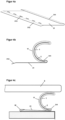
- the protective device is provided with a holder 3, which serves for easy positioning and mounting of the protective device on the edge of the roof ( Figure 4a ).
- the holder 3 comprises a first profile 31, which has a fold 311 on one edge.
- the first profile 31 is made of plastic or metal, in particular stainless steel, and preferably has the same length as the inner body 2 attached to it.
- an edge of the inner body 2 is inserted into the fold 311 and firmly clamped therein by pressing the fold 311 in ( Figure 4b ).
- the edge of the first profile 31 opposite the cover 311 is inserted into an existing water fold W attached to the roof ( Figure 4c ).
- the edge of the first profile 31 opposite the fold 311 has a bend 312.
- the first profile 31 can have openings 313 which serve to screw or nail the protective device.
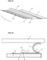
- the holder 3 also comprises a second profile 32, wherein the two profiles 31, 32 are connected to one another in parallel along their longitudinal direction ( Figure 5a ).
- the fold (311) is located on the edge of the first profile (31) opposite the second profile (32).
- the profiles 31, 32 are firmly connected to one another, preferably welded or riveted together, in particular they can be connected to one another by spot welding the second profile 32 onto the first profile 31.
- the second profile 32 is also made of plastic or metal, in particular stainless steel, and preferably has the same length as the inner body 2.
- the second profile 32 forms a raised web 321, which serves to bridge a water fold W on the edge of the roof and is obtained by bending or repeatedly folding the second profile 32 ( Figure 5b ).
- the end of the first profile 31 opposite the fold 311 to below the raised web 321 of the second profile 32 and into the water fold W.
- the second profile 32 may also have openings 322 for screwing or nailing the protection device to the roof structure.
- the protection device is dimensioned so that the inner and outer bodies 1, 2 are bent and clamped between the support 3 and the tiles Z in order to completely plug any passage between the tiles and the structure located underneath.
- An alternative fastening method is to attach an adhesive device, for example an adhesive tape or several adhesive dots, to the bracket 3.
- This fastening method is also possible for the protective device without a bracket, in which case the adhesive device is attached directly to the cover 11.
- the protective device can be easily attached anywhere, in particular around a roof window, or in other places where fastening with screws or nails is not possible or desired.
Landscapes
- Life Sciences & Earth Sciences (AREA)
- Engineering & Computer Science (AREA)
- Zoology (AREA)
- Insects & Arthropods (AREA)
- Pest Control & Pesticides (AREA)
- Wood Science & Technology (AREA)
- Birds (AREA)
- Environmental Sciences (AREA)
- Architecture (AREA)
- Civil Engineering (AREA)
- Structural Engineering (AREA)
- Catching Or Destruction (AREA)
- Building Environments (AREA)
Claims (11)
- Dispositif de protection pour enveloppe de bâtiment comprenant un corps extérieur malléable (1) et un corps intérieur plus rigide (2), oùle corps extérieur (1) est entièrement ou partiellement recouvert d'une enveloppe (11),le corps intérieur (2) est entièrement ou partiellement entouré par le corps extérieur (1), etl'enveloppe (11) est constituée d'une grille flexible, d'un tressage ou d'un tissu, elle est reliée au corps intérieur (2) et elle maintient le corps extérieur (1) autour du corps intérieur (2),caractérisé en ce quele corps extérieur (1) comprend une laine malléable en métal ou en plastique qui forme un coussin malléable autour du corps intérieur (2) et en ce que l'enveloppe (11) est constituée d'un tressage ou tissu métallique.
- Dispositif de protection selon la revendication 1,
caractérisé en ce que
le corps extérieur (1) comprend de la laine d'acier. - Dispositif de protection selon la revendication 1,
caractérisé en ce que
le corps interne (2) est une bande de matériau rigide mais déformable manuellement. - Dispositif de protection selon la revendication 1,
caractérisé en ce que
l'enveloppe (11) est constituée d'un tissu à maille circulaire en cuivre. - Dispositif de protection selon la revendication 1,
caractérisé par
un support (3) comprenant un premier profilé (31) qui présente un repli (311) sur un bord. - Dispositif de protection selon la revendication 5,
caractérisé en ce que
un bord du corps interne (2) est inséré dans le repli (311) et y est fermement serré par pincement du repli (311). - Dispositif de protection selon la revendication 5,
caractérisé en ce quele support (3) comprend un deuxième profilé (32) qui forme un pont surélevé (321),les premier et deuxième profilés (31, 32) étant reliés parallèlement l'un à l'autre le long de leur direction longitudinale. - Dispositif de protection selon la revendication 7,
caractérisé en ce que
l'extrémité du premier profilé (31) opposée au repli (311) s'étend au-dessous du pont surélevé (321) du deuxième profilé (32). - Dispositif de protection selon la revendication 1,
caractérisé en ce que
un dispositif adhésif est fixé sur l'enveloppe (11), grâce auquel le dispositif de protection peut être fixé à n'importe quel endroit de l'enveloppe du bâtiment. - Dispositif de protection selon la revendication 5,
caractérisé en ce que
un dispositif adhésif est fixé sur le support (3), grâce auquel le dispositif de protection peut être fixé à n'importe quel endroit de l'enveloppe du bâtiment. - Utilisation du dispositif de protection selon l'une des revendications précédentes,
caractérisé en ce que
le dispositif de protection est utilisé en bordure d'un toit de tuiles pour boucher les ouvertures (O) entre les tuiles (Z) et la structure sous-jacente.
Applications Claiming Priority (1)
| Application Number | Priority Date | Filing Date | Title |
|---|---|---|---|
| CH000686/2021A CH718723B1 (de) | 2021-06-11 | 2021-06-11 | Schutzvorrichtung für eine Gebäudehülle |
Publications (3)
| Publication Number | Publication Date |
|---|---|
| EP4102004A1 EP4102004A1 (fr) | 2022-12-14 |
| EP4102004C0 EP4102004C0 (fr) | 2024-11-06 |
| EP4102004B1 true EP4102004B1 (fr) | 2024-11-06 |
Family
ID=82214203
Family Applications (1)
| Application Number | Title | Priority Date | Filing Date |
|---|---|---|---|
| EP22176285.9A Active EP4102004B1 (fr) | 2021-06-11 | 2022-05-31 | Dispositif de protection pour une enveloppe de bâtiment |
Country Status (2)
| Country | Link |
|---|---|
| EP (1) | EP4102004B1 (fr) |
| CH (1) | CH718723B1 (fr) |
Family Cites Families (10)
| Publication number | Priority date | Publication date | Assignee | Title |
|---|---|---|---|---|
| US2035862A (en) * | 1934-11-19 | 1936-03-31 | Reginald B Calcutt | Weather strip |
| US2020103A (en) * | 1935-08-09 | 1935-11-05 | Reginald B Calcutt | Weather strip |
| US2459120A (en) * | 1942-03-23 | 1949-01-11 | Bridgeport Fabrics Inc | Method of making weather strips |
| US4081647A (en) * | 1976-05-10 | 1978-03-28 | Roper Corporation | Energy seal for a microwave oven |
| DE4404150C1 (de) * | 1994-02-10 | 1995-05-24 | Braas Gmbh | Lüftungsband |
| DE102008059134A1 (de) | 2008-11-26 | 2010-05-27 | Georg Meyer | Schutzvorrichtung |
| DE202012005768U1 (de) | 2012-06-06 | 2012-07-09 | Ralf Sattler | Schutzgitterdraht zum Fernhalten von Vögeln und Kleintieren im Dachbereich |
| US9867367B2 (en) * | 2013-03-06 | 2018-01-16 | Global Material Technologies, Incorporated | Entryway seals and vermin barrier |
| AU2016259406B2 (en) * | 2015-11-20 | 2022-05-12 | Fleet Building Services (Hampshire) Ltd | Roof edge seal and barrier devices and their manufacture |
| US20190242181A1 (en) * | 2018-02-08 | 2019-08-08 | Joan Clark | Pest Barrier Assembly |
-
2021
- 2021-06-11 CH CH000686/2021A patent/CH718723B1/de unknown
-
2022
- 2022-05-31 EP EP22176285.9A patent/EP4102004B1/fr active Active
Also Published As
| Publication number | Publication date |
|---|---|
| CH718723B1 (de) | 2024-07-15 |
| EP4102004A1 (fr) | 2022-12-14 |
| EP4102004C0 (fr) | 2024-11-06 |
| CH718723A2 (de) | 2022-12-15 |
Similar Documents
| Publication | Publication Date | Title |
|---|---|---|
| EP2096229B1 (fr) | Espaceur pour système d'enduit épais | |
| EP3040488B1 (fr) | Caniveau | |
| EP4368019A1 (fr) | Dispositif pour repousser des animaux, en particulier des oiseaux, de préférence des pigeons | |
| EP4102004B1 (fr) | Dispositif de protection pour une enveloppe de bâtiment | |
| DE102011117699A1 (de) | Befestigungsprofil, Verbindungselement und System für Lüftungsprofile für hinterlüftete Fassaden von Gebäuden | |
| DE202011003239U1 (de) | Schnee- und/oder Eisfangvorrichtung | |
| EP1135566B1 (fr) | Dispositif de fixation d'un tuyau de protection contre les feuillages, destine a etre place dans une gouttiere de toiture | |
| DE102013101207A1 (de) | Ablaufvorrichtung | |
| DE102008059134A1 (de) | Schutzvorrichtung | |
| DE29521345U1 (de) | Randabdeckungsprofil | |
| AT402833B (de) | Vorrichtung zur befestigung von firstabdeckungen am dachfirst einer dacheindeckung | |
| DE19726921C1 (de) | Schutzvorrichtung für Dachrinnen zur Verhinderung eines Laubeinfalles | |
| EP4331359A1 (fr) | Dispositif de verrouillage d'accès à un toit de bâtiment pour animaux | |
| DE19950472C1 (de) | Befestigungsvorrichtung für Laubschutzrohre | |
| DE202010010610U1 (de) | Lüftungsgitter | |
| EP4358716B1 (fr) | Dispositif de protection contre les oiseaux et agencement | |
| AT13022U1 (de) | Rinnenbürste | |
| CH451466A (de) | Vorrichtung zur Dachdurchführung von Entlüftungsrohren | |
| DE202008003318U1 (de) | Einrichtung zur Montage auf einem Dachfirst | |
| DE202022002419U1 (de) | Vorrichtung zur Abwehr von Tieren, insbesondere Vögeln, vorzugsweise von Tauben | |
| DE9210841U1 (de) | Luftdurchlässiges Schutzelement | |
| DE9420272U1 (de) | Abschirmung zur Verhinderung der Verstopfung von Regenrinnen | |
| DE102024002858A1 (de) | Vorrichtung zur Abwehr von Tieren, insbesondere von Vögeln, vorzugsweise von Tauben | |
| DE29918452U1 (de) | Befestigungsvorrichtung für Laubschutzrohre | |
| DE102019204684A1 (de) | Dachkonstruktion für Nutz- und/oder Wohngebäude und Verfahren zum Installieren einer Dachkonstruktion |
Legal Events
| Date | Code | Title | Description |
|---|---|---|---|
| PUAI | Public reference made under article 153(3) epc to a published international application that has entered the european phase |
Free format text: ORIGINAL CODE: 0009012 |
|
| STAA | Information on the status of an ep patent application or granted ep patent |
Free format text: STATUS: THE APPLICATION HAS BEEN PUBLISHED |
|
| AK | Designated contracting states |
Kind code of ref document: A1 Designated state(s): AL AT BE BG CH CY CZ DE DK EE ES FI FR GB GR HR HU IE IS IT LI LT LU LV MC MK MT NL NO PL PT RO RS SE SI SK SM TR |
|
| STAA | Information on the status of an ep patent application or granted ep patent |
Free format text: STATUS: REQUEST FOR EXAMINATION WAS MADE |
|
| 17P | Request for examination filed |
Effective date: 20230323 |
|
| RBV | Designated contracting states (corrected) |
Designated state(s): AL AT BE BG CH CY CZ DE DK EE ES FI FR GB GR HR HU IE IS IT LI LT LU LV MC MK MT NL NO PL PT RO RS SE SI SK SM TR |
|
| GRAP | Despatch of communication of intention to grant a patent |
Free format text: ORIGINAL CODE: EPIDOSNIGR1 |
|
| STAA | Information on the status of an ep patent application or granted ep patent |
Free format text: STATUS: GRANT OF PATENT IS INTENDED |
|
| RIC1 | Information provided on ipc code assigned before grant |
Ipc: A01M 29/30 20110101ALI20240510BHEP Ipc: E04D 13/00 20060101AFI20240510BHEP |
|
| INTG | Intention to grant announced |
Effective date: 20240531 |
|
| GRAS | Grant fee paid |
Free format text: ORIGINAL CODE: EPIDOSNIGR3 |
|
| GRAA | (expected) grant |
Free format text: ORIGINAL CODE: 0009210 |
|
| STAA | Information on the status of an ep patent application or granted ep patent |
Free format text: STATUS: THE PATENT HAS BEEN GRANTED |
|
| AK | Designated contracting states |
Kind code of ref document: B1 Designated state(s): AL AT BE BG CH CY CZ DE DK EE ES FI FR GB GR HR HU IE IS IT LI LT LU LV MC MK MT NL NO PL PT RO RS SE SI SK SM TR |
|
| REG | Reference to a national code |
Ref country code: GB Ref legal event code: FG4D Free format text: NOT ENGLISH |
|
| REG | Reference to a national code |
Ref country code: CH Ref legal event code: EP |
|
| REG | Reference to a national code |
Ref country code: DE Ref legal event code: R096 Ref document number: 502022002055 Country of ref document: DE |
|
| REG | Reference to a national code |
Ref country code: IE Ref legal event code: FG4D Free format text: LANGUAGE OF EP DOCUMENT: GERMAN |
|
| U01 | Request for unitary effect filed |
Effective date: 20241112 |
|
| U07 | Unitary effect registered |
Designated state(s): AT BE BG DE DK EE FI FR IT LT LU LV MT NL PT RO SE SI Effective date: 20241120 |
|
| PG25 | Lapsed in a contracting state [announced via postgrant information from national office to epo] |
Ref country code: IS Free format text: LAPSE BECAUSE OF FAILURE TO SUBMIT A TRANSLATION OF THE DESCRIPTION OR TO PAY THE FEE WITHIN THE PRESCRIBED TIME-LIMIT Effective date: 20250306 Ref country code: HR Free format text: LAPSE BECAUSE OF FAILURE TO SUBMIT A TRANSLATION OF THE DESCRIPTION OR TO PAY THE FEE WITHIN THE PRESCRIBED TIME-LIMIT Effective date: 20241106 |
|
| PG25 | Lapsed in a contracting state [announced via postgrant information from national office to epo] |
Ref country code: ES Free format text: LAPSE BECAUSE OF FAILURE TO SUBMIT A TRANSLATION OF THE DESCRIPTION OR TO PAY THE FEE WITHIN THE PRESCRIBED TIME-LIMIT Effective date: 20241106 |
|
| PG25 | Lapsed in a contracting state [announced via postgrant information from national office to epo] |
Ref country code: NO Free format text: LAPSE BECAUSE OF FAILURE TO SUBMIT A TRANSLATION OF THE DESCRIPTION OR TO PAY THE FEE WITHIN THE PRESCRIBED TIME-LIMIT Effective date: 20250206 |
|
| PG25 | Lapsed in a contracting state [announced via postgrant information from national office to epo] |
Ref country code: GR Free format text: LAPSE BECAUSE OF FAILURE TO SUBMIT A TRANSLATION OF THE DESCRIPTION OR TO PAY THE FEE WITHIN THE PRESCRIBED TIME-LIMIT Effective date: 20250207 |
|
| PG25 | Lapsed in a contracting state [announced via postgrant information from national office to epo] |
Ref country code: PL Free format text: LAPSE BECAUSE OF FAILURE TO SUBMIT A TRANSLATION OF THE DESCRIPTION OR TO PAY THE FEE WITHIN THE PRESCRIBED TIME-LIMIT Effective date: 20241106 |
|
| PG25 | Lapsed in a contracting state [announced via postgrant information from national office to epo] |
Ref country code: RS Free format text: LAPSE BECAUSE OF FAILURE TO SUBMIT A TRANSLATION OF THE DESCRIPTION OR TO PAY THE FEE WITHIN THE PRESCRIBED TIME-LIMIT Effective date: 20250206 |
|
| U20 | Renewal fee for the european patent with unitary effect paid |
Year of fee payment: 4 Effective date: 20250506 |
|
| PG25 | Lapsed in a contracting state [announced via postgrant information from national office to epo] |
Ref country code: SM Free format text: LAPSE BECAUSE OF FAILURE TO SUBMIT A TRANSLATION OF THE DESCRIPTION OR TO PAY THE FEE WITHIN THE PRESCRIBED TIME-LIMIT Effective date: 20241106 |
|
| PG25 | Lapsed in a contracting state [announced via postgrant information from national office to epo] |
Ref country code: SK Free format text: LAPSE BECAUSE OF FAILURE TO SUBMIT A TRANSLATION OF THE DESCRIPTION OR TO PAY THE FEE WITHIN THE PRESCRIBED TIME-LIMIT Effective date: 20241106 |
|
| PG25 | Lapsed in a contracting state [announced via postgrant information from national office to epo] |
Ref country code: CZ Free format text: LAPSE BECAUSE OF FAILURE TO SUBMIT A TRANSLATION OF THE DESCRIPTION OR TO PAY THE FEE WITHIN THE PRESCRIBED TIME-LIMIT Effective date: 20241106 |
|
| PLBE | No opposition filed within time limit |
Free format text: ORIGINAL CODE: 0009261 |
|
| STAA | Information on the status of an ep patent application or granted ep patent |
Free format text: STATUS: NO OPPOSITION FILED WITHIN TIME LIMIT |
|
| 26N | No opposition filed |
Effective date: 20250807 |
|
| PGFP | Annual fee paid to national office [announced via postgrant information from national office to epo] |
Ref country code: CH Payment date: 20250805 Year of fee payment: 4 |
|
| PG25 | Lapsed in a contracting state [announced via postgrant information from national office to epo] |
Ref country code: MC Free format text: LAPSE BECAUSE OF FAILURE TO SUBMIT A TRANSLATION OF THE DESCRIPTION OR TO PAY THE FEE WITHIN THE PRESCRIBED TIME-LIMIT Effective date: 20241106 |
|
| PG25 | Lapsed in a contracting state [announced via postgrant information from national office to epo] |
Ref country code: IE Free format text: LAPSE BECAUSE OF NON-PAYMENT OF DUE FEES Effective date: 20250531 |