EP4102020A1 - Keil mit einstellbarer dicke - Google Patents
Keil mit einstellbarer dicke Download PDFInfo
- Publication number
- EP4102020A1 EP4102020A1 EP21178466.5A EP21178466A EP4102020A1 EP 4102020 A1 EP4102020 A1 EP 4102020A1 EP 21178466 A EP21178466 A EP 21178466A EP 4102020 A1 EP4102020 A1 EP 4102020A1
- Authority
- EP
- European Patent Office
- Prior art keywords
- wall
- wedge
- sliding element
- removable
- sliding
- Prior art date
- Legal status (The legal status is an assumption and is not a legal conclusion. Google has not performed a legal analysis and makes no representation as to the accuracy of the status listed.)
- Withdrawn
Links
Images




Classifications
-
- E—FIXED CONSTRUCTIONS
- E04—BUILDING
- E04F—FINISHING WORK ON BUILDINGS, e.g. STAIRS, FLOORS
- E04F21/00—Implements for finishing work on buildings
- E04F21/0007—Implements for finishing work on buildings for mounting doors, windows or frames; their fitting
- E04F21/0015—Implements for finishing work on buildings for mounting doors, windows or frames; their fitting for mounting frames
-
- E—FIXED CONSTRUCTIONS
- E06—DOORS, WINDOWS, SHUTTERS, OR ROLLER BLINDS IN GENERAL; LADDERS
- E06B—FIXED OR MOVABLE CLOSURES FOR OPENINGS IN BUILDINGS, VEHICLES, FENCES OR LIKE ENCLOSURES IN GENERAL, e.g. DOORS, WINDOWS, BLINDS, GATES
- E06B1/00—Border constructions of openings in walls, floors, or ceilings; Frames to be rigidly mounted in such openings
- E06B1/56—Fastening frames to the border of openings or to similar contiguous frames
- E06B1/60—Fastening frames to the border of openings or to similar contiguous frames by mechanical means, e.g. anchoring means
- E06B1/6069—Separate spacer means acting exclusively in the plane of the opening; Shims; Wedges; Tightening of a complete frame inside a wall opening
Definitions
- the present invention relates to a wedge whose thickness is adjustable by a user.
- the document KR20110134578A describes a shim of variable thickness for controlling the horizontal of a door frame under construction.
- horizontal plates can be moved away from each other by moving lifting elements apart with the aid of a screw.
- a problem with this known device is that one of the horizontal plates must rest on a flat surface, otherwise the various parts of the device separate, and it can therefore only be used for a vertical thickness adjustment.
- An object of the present invention is to provide an adjustable shim that can be used to adjust a vertical thickness or a horizontal thickness.
- the wedge according to the invention operates as follows.
- the user actuates the actuator device, which moves the slider in the first direction.
- the movement of the sliding element generates a push or a pull on the mobile element, which moves in the second direction. Since the movable element passes through the opening, it then moves away from or approaches the bottom wall of the box.
- the thickness of the wedge given by the distance between the bottom wall of the box and the outer wall of the movable element, can be adjusted by actuating the actuator device
- the box prevents the movements of the sliding element and of the movable element in the third direction during their respective movements, it is possible to adjust a horizontal thickness by placing the wedge so that the third direction is vertical.
- the front of the wedge is the side of the wedge facing the user actuating the actuator device.
- the wedge can be made to be light enough to fit between two vertical surfaces, and inexpensive enough to be disposable.
- a wedge according to the invention can be offered in several models of different lengths since different lengths (in the first direction) make it possible to obtain different thickness ranges (in the second direction).
- the sliding element comprises a rear wall which is oblique with respect to the first and second directions
- the mobile element comprises a front wall which is oblique with respect to the first and second directions and configured to slide on the rear wall of the sliding element.
- the obliqueness allows the forward-backward movement in the first direction of the sliding element to cause movement of the movable element in the second direction.
- the driving of the movable element by the sliding element could be achieved in another way while remaining within the scope of the invention.
- the sliding element and the movable element are locked relative to each other in the third direction by a locking mechanism located on the sliding element and/or the movable element. This makes it possible to reduce the risks of a relative movement of the mobile element with respect to the sliding element in the third direction.
- the locking mechanism comprises a projecting plate located on the sliding element and perpendicular to the third direction, and a slot located on the movable element and arranged to receive, at least partially, the plaque.
- the slot extends in the first direction so that the plate can move in the slot when the actuator device is actuated.
- the blocking mechanism could be reversed, with a plate located on the movable element and the slot on the sliding element.
- the actuator device comprises a front hole passing through the front wall, and a rod passing through the front hole and having a first end intended to push and/or pull the sliding element and a second end, located outside the case, and intended to be actuated by the user.
- a first end intended to push and/or pull the sliding element
- a second end located outside the case, and intended to be actuated by the user.
- the actuator device can be arranged otherwise. It could, for example, include a self-locking mechanism allowing only the thickness to be increased and not to be reduced.
- the rod comprises a thread corresponding to the front hole, and in which the length of the housing is greater than or equal to the sum of the length of the sliding element and the length of the thread.
- the difference between the length of the box (that is to say its internal length) and the length of the sliding element is the maximum amplitude of the displacement of the sliding element in the first direction.
- This maximum amplitude of movement is equal to or greater than the length of the thread prevents the user from pushing the rod too far into the box, which could push the sliding element against the rear wall, with a risk of causing the sliding element to come out of the case or of breaking the wedge.
- the box comprises fixing elements making it possible to attach the rear wall to a first surface or to a second surface outside the wedge.
- the case may include adhesive to bond the rear wall to the exterior surface, and/or holes in the rear wall and/or tabs to screw the rear wall against the first surface.
- the wedge comprises a retaining mechanism configured to retain the movable element and the sliding element at least partially in the housing in the absence of actuation of the actuator device, and to allow a displacement of the sliding element in the first direction and displacement of the movable element in the second direction during actuation of the actuator device.
- the various elements remain together before actuating the wedge.
- the retaining mechanism comprises teeth located on a first wall and a second wall of the case, and recesses located on a first wall and a second wall of the movable element, and provided for receive the teeth; the first and second walls of the casing and the first and second walls of the mobile element being perpendicular to the third direction; the wedge being configured so that the teeth move apart when the movable element is moved by the sliding element.
- the teeth are on the internal face of the first and second walls of the case.
- the movable element comprises a main element configured to be moved by the sliding element, and a first removable element configured to be removably fixed to the main element and to increase the thickness of the movable element in the second direction.
- the external wall of the mobile element can then be a support wall for the main element if the removable element is not present, or a support wall for the removable element if it is present.
- the thickness adjustment can then be made in two combinable ways: at least one removable element provides a thickness, which can be varied (by omitting the first removable element, by attaching an additional removable element to it and/or by replacing it with a removable replacement element) and the movement of the mobile element provides another thickness, which can also be varied (by activating the device actuator).
- the variation in thickness originating from the movement of the movable element allows finer adjustment than the variation in thickness originating from the removable element.
- the removable attachment between the main element and the first removable element comprises a tenon and a mortise.
- the tenon and the mortise preferentially extend along the first direction. They are preferably provided for sliding in the first direction and blocking in the second and third directions. This makes it possible to slide the first removable element on the main element when the casing, the sliding element and the main element are already in the space between the first and second surfaces.
- the wedge comprises an additional removable element configured to be removably fixed to the first removable element and to increase the thickness of the mobile element in the second direction. It is thus possible to superimpose removable elements in order to obtain a great thickness.
- the invention also relates to an assembly comprising the wedge comprising the main element and the first removable element, and at least one replacement removable element configured to be fixed to the main element in place of the first removable element, the removable replacement and the first removable element having different thicknesses.
- the assembly thus comprises a set of at least two removable elements. This makes it possible to give a wide range of possible thicknesses.
- the invention also relates to a kit comprising a wedge and a holding element comprising two clamps fixed to a rigid rod and configured to hold the two vertical uprights of a door at a fixed distance from each other.
- the housing is fixed relative to the first surface during actuation of the actuator device. It can for example be fixed to the first surface.
- the first surface is for example on a door jamb, frame, frame, and the second surface on a wall.
- the first surface is for example any element requiring precise and easy mounting.
- the method can be carried out for several wedges, for example, two wedges for each vertical upright, and optionally one wedge for the horizontal upright.
- the establishment of a frame may require the use of at least four or five wedges.
- the rods of the actuator devices can be broken or removed, so as not to protrude forward from the door jambs.
- a foam can then be dispensed between the frame and the wall. The wedges will then be embedded in the foam.
- the first removable element can be attached to the main element while the housing is still outside the space between the surfaces, or when the housing is already in the space between the surfaces.
- first and second are used only to differentiate the different elements and do not imply an order between these elements.
- the figure 1 schematically illustrates a door frame 300 wedged into the hole in a wall by four wedges 100.
- the door frame 300 comprises two vertical uprights 301 and a horizontal upright.
- the vertical uprights 301 are held at a distance from each other by means of two holding elements 200 comprising two clamps or jaws 201 fixed to a rigid rod 202.
- the wedges 100 are located in a space 310 between the frame 300 and the wall.
- the wedges 100 according to the invention comprise a casing 10, a sliding element 20, a movable element 30, and an actuator device. Possible embodiments of these elements are described with reference to the following figures with reference to a first 101, a second 102 and a third 103 directions, which are mutually perpendicular.
- the adjustable thickness thanks to the wedge 100 is the extent of the wedge 100 along the second direction 102.
- the figure 2 illustrates a possible embodiment of the box 10. It preferably comprises a front wall 15 and a rear wall 16 perpendicular to the first direction 101, a bottom wall 13 perpendicular to the second direction 102, an opening 11 in a plane perpendicular to the second direction 102, and a first wall 17 and a second wall 18 perpendicular to the third direction 103.
- the side 14 of the case opposite the bottom wall 13 can be present and crossed by the opening 11, or be absent.
- the front wall 15 and the rear wall 16 are spaced apart by a length 12 along the first direction 101.
- the front wall 15 is traversed by a front hole 51, preferably threaded, forming part of a possible embodiment of the actuator device.
- the box 10 may include at least one fixing hole 60, located in the bottom wall 13 and/or in the lugs 61.
- the holes 60 in the lugs 61 are preferred to the holes 60 in the bottom wall 13 because the placement of the latter requires removing the sliding element 20 and the movable element 30.
- the length 12 of the box 10 is preferably between 4 cm and 15 cm.
- the width of the box 10 is preferably between 2 cm and 4 cm.
- the thickness of the box 10 is preferably between 2 cm and 4 cm.
- the figures 3a and 3b illustrate a possible embodiment of the sliding element 20. It preferably comprises a front wall 25 perpendicular to the first direction 101, a bottom wall 23 perpendicular to the second direction 102, and a first wall and a second wall 28 perpendicular to the third direction 103. It also comprises a rear wall 26 oblique with respect to the first 101 and second 102 directions, so that it has a thickness, in the second direction 102, greater at the front than at the rear .
- the sliding element 20 is configured to be, at least partly, in the box 10, so that its first wall slides along the first direction 101 against the first wall 17 of the box 10, and is locked in the third direction. 103 by the first wall 17 of the box 10; that its second wall 28 slides in the first direction 101 against the second wall 18 of the box 10 and is blocked in the third direction 103 by the second wall 18 of the box 10; and in that its bottom wall 23 slides in the first direction 101 against the bottom wall 13 of the box 10 and is blocked in the second direction 102 by the bottom wall 13 of the box 10.
- the length 22 of the sliding element 20, in the first direction 101, is less than the length 12 of the box 10. It can preferably slide in the box between a first position in which its front wall 25 is blocked by the front wall 15 of the box 10, and a second position in which the end of its rear wall 26 is blocked by the rear wall 16 of the box 10.
- the thickness of the sliding element 20, according to the second direction 102 is preferably equal to or less than the thickness of the case 10.
- the width of the sliding element 20, according to the third direction 103 is preferably less than equal to the inside width of the box 10.
- the sliding element 20 may comprise a plate 71 projecting from the rear wall 26.
- the plate 71 is arranged to engage movably along the first direction 101 and the second direction 102, in a slot 72 of the element. mobile 30, thus forming a blocking mechanism blocking the sliding element 20 and the mobile element 30 in the third direction 103.
- Sliding member 20 may include a recess 52 aligned with front hole 51 and forming part of one possible embodiment of the actuator device.
- the figure 4 illustrates a possible embodiment of the movable element 30. It preferably comprises a rear wall 36 (visible figure 9 ) perpendicular to the first direction 101, a bottom wall 33 perpendicular to the second direction 102, and a first wall 37 (visible figure 9 ) and a second wall 38 perpendicular to the third direction 103. It also comprises a front wall 35 oblique with respect to the first 101 and second 102 directions, so that it has a thickness, in the second direction 102, greater at the back than in front. It also includes a support wall 34 opposite the bottom wall 13 of the box 10 and located outside the box 10. It can also include an additional wall 39, making the junction between the front wall 35 and the support wall 34. It can also include a flat slot 72 extending along the first 101 and the second 102 directions. The length, along the first direction 101, of the bottom wall 33 is preferably smaller than or equal to the amplitude of movement of the movable element 20 along the first direction 101.
- the movable element 30 is configured to be engaged in the box 10, so that its first wall slides in the second direction 102 against the first wall 17 of the box 10, and is blocked in the third direction 103 by the first wall 17 of case 10; that its second wall 38 slides in the second direction 102 against the second wall 18 of the box 10 and is blocked in the third direction 103 by the second wall 18 of the box 10; and that its rear wall 36 slides along the second direction 102 against the rear wall 16 of the box 10 and is blocked in the first direction 101 by the rear wall 16 of the box 10.
- the figure 5 illustrates a rod 53 forming part of a possible embodiment of the actuator device.
- the rod 53 is provided to pass through the hole 51 and so that its thread 56 fits into the thread of the hole 51.
- Its first end 54 is located in the box 10 and is intended to push and/or pull the sliding element 20.
- Its second end 55, opposite the first end 54 in the first direction 101, is located on the other side of the front wall 15 and is intended to be actuated by the user.
- the first end 54 can for example be received in the recess 52 and/or be fixed to the sliding element 20. It preferably comprises a recess 58 followed by a widening 59 so that the widening is located in the recess. 52 and can pull the sliding element 20 towards the front wall 15.
- the second end 55 is preferably arranged to be able to be turned by hand, without a screwdriver, for example thanks to a T-shape.
- the second end 55 is preferably arranged to be able to be broken, so as to reduce the length of the wedge 100 according to the first direction 101.
- the length 57 of the thread 56 of the rod 53 is less than or equal to the difference 107 between the length 12 of the housing 10 and the length 22 of the sliding element 20 (visible figure 6a ).
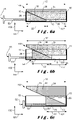
- the figures 6a to 6c illustrates a mode of operation of a wedge 100 according to one embodiment of the invention.
- the wedge 100 as shown in figure 6a , is placed in a space 310 between a first 302 and a second 303 surfaces which face each other in the second direction 102, so that the second end 55 of the rod 53 is towards the user.
- the figures 6b and 6c illustrate what happens when the user moves the rod 53 along the first direction 101, from front to back.
- the first end 54 of the rod 53 pushes the sliding element 20 along the first direction 101, from front to rear.
- the rear wall 26 of the sliding element 20 pushes the front wall 35 of the movable element 30.
- the front wall 35 of the movable element 30 slides against the rear wall 26 of the sliding element 20, and the movable element 30 moves in the second direction 102, away from the wall of the bottom 13.
- Its bearing wall 34 (or 84 or 94 as described below), which forms its outer wall, can then move closer to the second surface 303. If the user lets go of the rod 53, the movable element 30 remains in place. If the user moves the rod 53 from the back to the front, the movable element 30 can move closer to the bottom wall 13 so as to reduce the thickness of the wedge 100.
- the figures 7a to 7c illustrates a mode of operation of a wedge 100 according to another embodiment of the invention.
- the sliding element 20 comprises an additional wall 29, making the junction between the rear wall 26 and the bottom wall 23 and able to abut against the rear wall 16 of the box 10.
- the additional wall 29 can be perpendicular to the first direction 101.
- the embodiment of the figures 7a to 7c allows better stability of the wedge than the embodiment of the figures 6a to 6c , in particular at the maximum position illustrated in figure 6c and 7c .
- the slope of the rear wall 26 being lower in the embodiment of the figures 7a to 7c that in the embodiment of figures 6a to 6c , the latter allows greater variability in the thickness of the wedge 100.
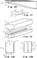
- the figure 8 is another illustration of the sliding element 20 of the figures 7a to 7c .
- the figure 9 illustrates another possible embodiment of the movable element 30, in which the movable element 30 comprises a main element 80 in contact with the sliding element 20, and a first removable element 90 which can be removably attached to the main element 80.
- the main element 80 comprises a bearing wall 84, perpendicular to the second direction 102, which forms the outer wall of the wedge 100 if the first removable element 90 is absent.
- the first removable element 90 comprises a bearing wall 94, perpendicular to the second direction 102, and which forms the outer wall of the wedge 100 if the first removable element 90 is present. It also includes a bottom wall 93 opposite the support wall 94 and in contact with the main element 80.
- the removable attachment between the main element 80 and the first removable element 90 comprises a mortise 81 and a tenon 91, respectively located on the support wall 84 of the main element 80 and on the bottom wall 93 of the first removable element 90, or vice versa.
- the mortise 81 and tenon 91 preferably have a parallelogram shape in a plane perpendicular to the first direction 101.
- An assembly according to the invention can comprise several removable elements, among which the first removable element and other removable elements that can be put in its place and have different thicknesses, in the second direction 102 .
- the figure 10 illustrates a variant of the main element 80. It could for example be suitable for the embodiment of the wedge 100 illustrated in figures 7a to 7c .
- the figures 11 and 12 illustrate that removable elements can also be provided to attach to each other.
- the first removable element 90 can for example be as illustrated in figures 11 and 12 and include a tenon 91 on the bottom wall 93 and a mortise 92 on the support wall 94.
- the mortise 92 makes it possible to fix an additional removable element 99.
- the first removable element 90 and the additional removable element 99 can be of same thickness or different thicknesses.
- Each removable element preferably has a thickness of between 0.5 cm and 4 cm.
- the figures 13a and 13b illustrate an example of housing 10 and main element 80 in an embodiment of the invention comprising a retaining mechanism.
- the retaining mechanism makes it possible to fix the movable element 30 and the sliding element 20 to the box 10 in the absence of actuation of the actuator device, and allows a displacement of the sliding element 20 according to the first direction 101 and a displacement of the movable element 30 in the second direction 102 during actuation of the actuator device.
- the retaining mechanism may for example comprise teeth 41 on the internal faces of the first 17 and the second 18 walls of the case 10, and recesses, for example slots, 42 in the external faces of the first 37 and the second 38 walls of the movable element 30.
- the teeth 41 are in the recesses 42, which blocks the movable element 30 in the second direction 102.
- the sliding element 20 partly located between the movable element 30 and the bottom wall 13 in the second direction, it is also blocked.
- the actuator device moves the sliding element 20 from front to rear, the pressure exerted by the movable element 30 to move away from the bottom wall causes the teeth 41 to move apart, and therefore allows movement along the second direction 102.
- Rod 53 is preferably metallic.
- the other elements of the wedge 100 are preferably made of polymer (for example PVC), of wood and/or of metal.
- the box 10 can be a bent sheet.
- the bottom wall of the boxes is fixed to the first surface 302, which is the outer surface of the vertical uprights 301, and the outer wall 94 of the first removable element 90 is against the second surface 303, which is the surface of the wall.
- the attachment could be reversed while remaining within the scope of the invention.
- the user can place the wedges 100, and, in order to adjust the verticality of the vertical uprights, adjust the thicknesses of the wedges 100 by replacing the first removable element 90 with a replacement element and/or by adding an additional removable element 99 and /or by actuating the actuator device. Then he breaks or removes rod 53 and injects foam into space 310.
- a shim could also be placed in the gap between the lintel and the horizontal jamb of the door and so as to adjust the horizontality of the horizontal jamb.
- the invention relates to a wedge 100 whose thickness can be adjusted using an actuator device.
- An actuation of the actuator device causes a movement of a sliding element 20 in a housing 10 and in a first direction 101.
- the displacement of the sliding element 20 causes a displacement, in a second direction 102, of a movable element 30, thus increasing the distance between an outer wall 34, 84, 94 of the movable element 34 and a wall of bottom 13 of case 10, and therefore the thickness of shim 100.
Landscapes
- Engineering & Computer Science (AREA)
- Architecture (AREA)
- Civil Engineering (AREA)
- Structural Engineering (AREA)
- Mechanical Engineering (AREA)
- Transmission Devices (AREA)
- Power-Operated Mechanisms For Wings (AREA)
- Conveying And Assembling Of Building Elements In Situ (AREA)
- Standing Axle, Rod, Or Tube Structures Coupled By Welding, Adhesion, Or Deposition (AREA)
- Door And Window Frames Mounted To Openings (AREA)
- Telephone Set Structure (AREA)
Priority Applications (8)
| Application Number | Priority Date | Filing Date | Title |
|---|---|---|---|
| EP21178466.5A EP4102020A1 (de) | 2021-06-09 | 2021-06-09 | Keil mit einstellbarer dicke |
| CA3221114A CA3221114A1 (fr) | 2021-06-09 | 2022-06-07 | Cale d'epaisseur ajustable |
| BE20225438A BE1029045B1 (fr) | 2021-06-09 | 2022-06-07 | Cale d'épaisseur ajustable |
| EP22740297.1A EP4352332B1 (de) | 2021-06-09 | 2022-06-07 | Keil mit einstellbarer dicke |
| PCT/EP2022/065416 WO2022258626A1 (fr) | 2021-06-09 | 2022-06-07 | Cale d'épaisseur ajustable |
| US18/568,181 US20240151096A1 (en) | 2021-06-09 | 2022-06-07 | Shim with adjustable thickness |
| JP2023575978A JP2024521960A (ja) | 2021-06-09 | 2022-06-07 | 調整可能な厚さを有するシム |
| CN202280040514.2A CN117460875A (zh) | 2021-06-09 | 2022-06-07 | 厚度可调的垫块 |
Applications Claiming Priority (1)
| Application Number | Priority Date | Filing Date | Title |
|---|---|---|---|
| EP21178466.5A EP4102020A1 (de) | 2021-06-09 | 2021-06-09 | Keil mit einstellbarer dicke |
Publications (1)
| Publication Number | Publication Date |
|---|---|
| EP4102020A1 true EP4102020A1 (de) | 2022-12-14 |
Family
ID=76355364
Family Applications (2)
| Application Number | Title | Priority Date | Filing Date |
|---|---|---|---|
| EP21178466.5A Withdrawn EP4102020A1 (de) | 2021-06-09 | 2021-06-09 | Keil mit einstellbarer dicke |
| EP22740297.1A Active EP4352332B1 (de) | 2021-06-09 | 2022-06-07 | Keil mit einstellbarer dicke |
Family Applications After (1)
| Application Number | Title | Priority Date | Filing Date |
|---|---|---|---|
| EP22740297.1A Active EP4352332B1 (de) | 2021-06-09 | 2022-06-07 | Keil mit einstellbarer dicke |
Country Status (7)
| Country | Link |
|---|---|
| US (1) | US20240151096A1 (de) |
| EP (2) | EP4102020A1 (de) |
| JP (1) | JP2024521960A (de) |
| CN (1) | CN117460875A (de) |
| BE (1) | BE1029045B1 (de) |
| CA (1) | CA3221114A1 (de) |
| WO (1) | WO2022258626A1 (de) |
Families Citing this family (1)
| Publication number | Priority date | Publication date | Assignee | Title |
|---|---|---|---|---|
| WO2025052250A1 (en) * | 2023-09-04 | 2025-03-13 | Wilton Dave | A shim assembly |
Citations (4)
| Publication number | Priority date | Publication date | Assignee | Title |
|---|---|---|---|---|
| DE102006012390A1 (de) * | 2006-03-17 | 2007-09-20 | PHI Technik für Fenster und Türen GmbH | Keilvorrichtung |
| KR20110134578A (ko) | 2010-06-09 | 2011-12-15 | 주육환 | 시공시에 문틀의 수평을 조절하는 장치 |
| CN102620120A (zh) * | 2012-04-20 | 2012-08-01 | 大连华根机械有限公司 | 可调式垫铁装置 |
| WO2020011846A1 (de) * | 2018-07-12 | 2020-01-16 | Konold Härtsfelder Holzindustrie GmbH | Abstandshalter zur einstellung eines sollabstandes zwischen zwei komponenten und verfahren zur ausrichtung zweier komponenten zueinander |
Family Cites Families (46)
| Publication number | Priority date | Publication date | Assignee | Title |
|---|---|---|---|---|
| US464921A (en) * | 1891-12-08 | Warren ii | ||
| US875775A (en) * | 1907-08-29 | 1908-01-07 | Edwin Burhorn | Floor. |
| US1045984A (en) * | 1911-10-10 | 1912-12-03 | Charles W King | Wedge mechanism. |
| US2651814A (en) * | 1952-05-22 | 1953-09-15 | Jr Lawson L Lester | Doorframe |
| US2819037A (en) * | 1955-10-12 | 1958-01-07 | Norman M Wilkin | Leveling device |
| US3171632A (en) * | 1963-06-07 | 1965-03-02 | Sidney M Jines | Leveling device |
| US3306562A (en) * | 1965-02-15 | 1967-02-28 | J Paul A Bellefleur | Self-aligning machine levelers |
| DE1509901A1 (de) * | 1965-07-27 | 1969-07-10 | Schuermann & Co Heinz | Klotzung fuer Scheiben und Fuellungen in Fenster- und Tuerfluegeln |
| CH518771A (de) * | 1970-05-30 | 1972-02-15 | Waldrich Werkzeugmasch | Ausrichtvorrichtung für Werkstücke auf Werkzeugmaschinentischen |
| US3836118A (en) * | 1973-09-20 | 1974-09-17 | Usm Corp | Adjustable work support assembly |
| DK144280C (da) * | 1976-03-19 | 1982-07-05 | K Jensen | Opklodsningskile |
| US4354770A (en) * | 1980-05-19 | 1982-10-19 | The United States Of America As Represented By The Secretary Of The Navy | Wedge assembly |
| US4436268A (en) * | 1981-07-20 | 1984-03-13 | Schriever Frederick G | Self-aligning load leveling device |
| DE3502959C2 (de) * | 1985-01-30 | 1994-09-15 | Boegle Kg Wilhelm | Keil zur Anwendung an Lattenunterkonstruktionen von Wandungsverkleidungen |
| US4713922A (en) * | 1986-09-10 | 1987-12-22 | Ingold John P | Frame mounting structure for a housing opening and method therefore |
| US4829727A (en) * | 1986-12-31 | 1989-05-16 | Pressteel, Inc. | Method and apparatus for preparing a frame for installation in a door opening |
| US4805358A (en) * | 1987-04-27 | 1989-02-21 | H. H. Robertson Company | Electrical trench assembly |
| US4776548A (en) * | 1987-07-20 | 1988-10-11 | Bezenek Barry C | Leveling device |
| US4790515A (en) * | 1987-07-27 | 1988-12-13 | Silvano Pocci | Force multiplier useful as a lifting device |
| US5090664A (en) * | 1991-04-10 | 1992-02-25 | General Electric Company | Combination jack and roller for precision movement of heavy loads |
| US5427349A (en) * | 1992-04-13 | 1995-06-27 | Reo Hydraulic Pierce & Form, Inc. | Adjustable base assembly |
| CA2137407C (en) * | 1994-12-06 | 2002-04-30 | Ricci, Fernando | Shimming device for level adjustment of frame mounted in a wall opening |
| US5584464A (en) * | 1995-02-15 | 1996-12-17 | Unisorb Inc. | Quick adjustment heavy duty machinery mount |
| US6702246B1 (en) * | 1995-05-23 | 2004-03-09 | Frederick G. Schriever | Machine leveler |
| US5775036A (en) * | 1996-04-15 | 1998-07-07 | Stanley, Sr.; Jesse M. | Alignment of objects |
| US5655343A (en) * | 1996-07-09 | 1997-08-12 | Fred Seals Construction, Inc. | Apparatus and method for an adjustable shim for doors and windows |
| DE19821078C1 (de) * | 1998-05-12 | 1999-11-11 | Falk Naumann | Vorrichtung zum Verklotzen von Fenster- und Türelementen |
| US6018916A (en) * | 1998-09-15 | 2000-02-01 | Henry; Mark | Door and window shim |
| US6233901B1 (en) * | 1999-11-08 | 2001-05-22 | John R. Kurfees | Door frame installation kit |
| PL195181B1 (pl) * | 2001-03-30 | 2007-08-31 | Marcin Tasiemski | Klin montażowy |
| DE10148261C1 (de) * | 2001-09-28 | 2003-07-03 | Juergen Goroncy | Verstellbares Distanzstück |
| US20030145531A1 (en) * | 2002-02-05 | 2003-08-07 | Bruce Holder | Apparatus & method for shimming surfaces |
| EP1709277A1 (de) * | 2004-01-13 | 2006-10-11 | Itools APS | Abstandsstück |
| US7703727B2 (en) * | 2004-07-21 | 2010-04-27 | Selness Jerry N | Universal adjustable spacer assembly |
| US20060283130A1 (en) * | 2005-06-07 | 2006-12-21 | William Andrews | Structural members with gripping features and joining arrangements therefor |
| US7784751B1 (en) * | 2007-05-01 | 2010-08-31 | Focus 12 Inc. | Stabilizing device, along with modular configurations incorporating the same |
| DK176854B1 (da) * | 2007-08-16 | 2009-12-14 | Junckers Ind As F | Kilesæt, især til brug ved opklodsning af gulvströer |
| US7905465B1 (en) * | 2009-05-14 | 2011-03-15 | Softway Industrial Solutions, Llc | Shimless aligner |
| US8813437B1 (en) * | 2013-05-13 | 2014-08-26 | Charles J. Spofford | Integral shim-pack with an adjustment pull tang |
| DE102013105257B4 (de) * | 2013-05-23 | 2022-12-08 | Tobias Kniegl | Doppelkeil zum Rahmensetzen |
| US8925258B1 (en) * | 2014-01-27 | 2015-01-06 | Gregory Header | Wall and door panel adjustment device |
| US20150289649A1 (en) * | 2014-04-15 | 2015-10-15 | Denis Perrin | Interlocking Stabilizing Device |
| US11795756B2 (en) * | 2021-05-20 | 2023-10-24 | Denis Friezner | Adjustable shim assembly |
| DK181205B1 (en) * | 2021-09-27 | 2023-04-27 | Tillex V/Kim Tillegreen | Wedge, wedge system and method for bricking up building elements |
| US20230304352A1 (en) * | 2022-03-22 | 2023-09-28 | Denis Friezner | Adjustable Shim Assembly |
| US11933098B1 (en) * | 2023-03-20 | 2024-03-19 | Pella Corporation | Fenestration unit with interior installation features and associated systems and methods |
-
2021
- 2021-06-09 EP EP21178466.5A patent/EP4102020A1/de not_active Withdrawn
-
2022
- 2022-06-07 CN CN202280040514.2A patent/CN117460875A/zh active Pending
- 2022-06-07 BE BE20225438A patent/BE1029045B1/fr active IP Right Grant
- 2022-06-07 WO PCT/EP2022/065416 patent/WO2022258626A1/fr not_active Ceased
- 2022-06-07 CA CA3221114A patent/CA3221114A1/fr active Pending
- 2022-06-07 US US18/568,181 patent/US20240151096A1/en not_active Abandoned
- 2022-06-07 JP JP2023575978A patent/JP2024521960A/ja active Pending
- 2022-06-07 EP EP22740297.1A patent/EP4352332B1/de active Active
Patent Citations (4)
| Publication number | Priority date | Publication date | Assignee | Title |
|---|---|---|---|---|
| DE102006012390A1 (de) * | 2006-03-17 | 2007-09-20 | PHI Technik für Fenster und Türen GmbH | Keilvorrichtung |
| KR20110134578A (ko) | 2010-06-09 | 2011-12-15 | 주육환 | 시공시에 문틀의 수평을 조절하는 장치 |
| CN102620120A (zh) * | 2012-04-20 | 2012-08-01 | 大连华根机械有限公司 | 可调式垫铁装置 |
| WO2020011846A1 (de) * | 2018-07-12 | 2020-01-16 | Konold Härtsfelder Holzindustrie GmbH | Abstandshalter zur einstellung eines sollabstandes zwischen zwei komponenten und verfahren zur ausrichtung zweier komponenten zueinander |
Also Published As
| Publication number | Publication date |
|---|---|
| EP4352332A1 (de) | 2024-04-17 |
| US20240151096A1 (en) | 2024-05-09 |
| BE1029045B1 (fr) | 2023-06-16 |
| EP4352332B1 (de) | 2025-09-17 |
| WO2022258626A1 (fr) | 2022-12-15 |
| CN117460875A (zh) | 2024-01-26 |
| CA3221114A1 (fr) | 2022-12-15 |
| EP4352332C0 (de) | 2025-09-17 |
| JP2024521960A (ja) | 2024-06-04 |
| BE1029045A1 (fr) | 2022-08-19 |
Similar Documents
| Publication | Publication Date | Title |
|---|---|---|
| FR2638654A1 (fr) | Fixation de securite pour ski | |
| EP2636815B1 (de) | Bügel zum Befestigen eines Handlaufs eines Geländers auf einem Pfosten | |
| WO2018215699A1 (fr) | Joint de dilatation a renovation facilitee pour systeme de coffrage de dalles de beton | |
| BE1029045B1 (fr) | Cale d'épaisseur ajustable | |
| WO2006095058A1 (fr) | Outil de coupe pour decouper une plaque | |
| FR2900176A1 (fr) | Structure de soutien d'un coffrage de dalle ou analogue | |
| EP2980331B1 (de) | Vorrichtung zum befestigen von glaspaneelen, die eine brüstung bilden | |
| EP2138638A1 (de) | Grundanker mit Vorrichtung zur Verspreizung im Erdreich | |
| EP4190998A1 (de) | Vorrichtung zum halten eines flügels | |
| EP0559988A1 (de) | Einrichtung zum Befestigen eines Führungsschuhs auf dem unteren Teil einer Aufzugsschiebetür | |
| FR2937987A1 (fr) | Dispositif de fixation d'une suspente pour faux-plafond. | |
| EP3483339A1 (de) | Betonierfugenausbildung in der bodenplatte mit einfacherer reparierung | |
| FR2986542A1 (fr) | Pieu d'ancrage | |
| FR3029550A1 (fr) | Dispositif de montage provisoire d'elements sur une poutre de structure de batiment | |
| EP2527191B1 (de) | Verankerungssystem zum Verankern eines Sitzes am Boden | |
| FR3063510A1 (fr) | Dispositif de pivot pour une porte | |
| FR2607548A3 (fr) | Cale d'entretoisement notamment pour le montage des batis de fenetres et analogues | |
| EP3130507B1 (de) | Befestigungssystem und -schiene | |
| FR3016381A1 (fr) | Bras lateraux pour banche de coffrage. | |
| FR2989337A1 (fr) | Dispositif de support d'une charge pour une camionnette a plateau decouvert, et camionnette pourvue d'un tel dispositif de support | |
| EP4717634A1 (de) | Vorrichtung zur befestigung einer förderrolle | |
| FR3065188B1 (fr) | Dispositif de maintien d'un panneau sur un vehicule pour le transport dudit panneau | |
| FR2922232A1 (fr) | Element pour fixer une lisse d'une glissiere de securite sur un support | |
| WO2013150208A1 (fr) | Boitier de commande interne d'ouverture de porte | |
| BE1013360A6 (fr) | Support de coffrage pour un escalier en beton. |
Legal Events
| Date | Code | Title | Description |
|---|---|---|---|
| STAA | Information on the status of an ep patent application or granted ep patent |
Free format text: STATUS: EXAMINATION IS IN PROGRESS |
|
| PUAI | Public reference made under article 153(3) epc to a published international application that has entered the european phase |
Free format text: ORIGINAL CODE: 0009012 |
|
| 17P | Request for examination filed |
Effective date: 20220210 |
|
| AK | Designated contracting states |
Kind code of ref document: A1 Designated state(s): AL AT BE BG CH CY CZ DE DK EE ES FI FR GB GR HR HU IE IS IT LI LT LU LV MC MK MT NL NO PL PT RO RS SE SI SK SM TR |
|
| STAA | Information on the status of an ep patent application or granted ep patent |
Free format text: STATUS: THE APPLICATION IS DEEMED TO BE WITHDRAWN |
|
| 18D | Application deemed to be withdrawn |
Effective date: 20230503 |