EP4102202A2 - Élément récepteur - Google Patents
Élément récepteur Download PDFInfo
- Publication number
- EP4102202A2 EP4102202A2 EP22177140.5A EP22177140A EP4102202A2 EP 4102202 A2 EP4102202 A2 EP 4102202A2 EP 22177140 A EP22177140 A EP 22177140A EP 4102202 A2 EP4102202 A2 EP 4102202A2
- Authority
- EP
- European Patent Office
- Prior art keywords
- pressure
- shock wave
- longitudinal axis
- determined
- section
- Prior art date
- Legal status (The legal status is an assumption and is not a legal conclusion. Google has not performed a legal analysis and makes no representation as to the accuracy of the status listed.)
- Pending
Links
Images


Classifications
-
- G—PHYSICS
- G01—MEASURING; TESTING
- G01L—MEASURING FORCE, STRESS, TORQUE, WORK, MECHANICAL POWER, MECHANICAL EFFICIENCY, OR FLUID PRESSURE
- G01L23/00—Devices or apparatus for measuring or indicating or recording rapid changes, such as oscillations, in the pressure of steam, gas, or liquid; Indicators for determining work or energy of steam, internal-combustion, or other fluid-pressure engines from the condition of the working fluid
-
- G—PHYSICS
- G01—MEASURING; TESTING
- G01L—MEASURING FORCE, STRESS, TORQUE, WORK, MECHANICAL POWER, MECHANICAL EFFICIENCY, OR FLUID PRESSURE
- G01L23/00—Devices or apparatus for measuring or indicating or recording rapid changes, such as oscillations, in the pressure of steam, gas, or liquid; Indicators for determining work or energy of steam, internal-combustion, or other fluid-pressure engines from the condition of the working fluid
- G01L23/08—Devices or apparatus for measuring or indicating or recording rapid changes, such as oscillations, in the pressure of steam, gas, or liquid; Indicators for determining work or energy of steam, internal-combustion, or other fluid-pressure engines from the condition of the working fluid operated electrically
- G01L23/10—Devices or apparatus for measuring or indicating or recording rapid changes, such as oscillations, in the pressure of steam, gas, or liquid; Indicators for determining work or energy of steam, internal-combustion, or other fluid-pressure engines from the condition of the working fluid operated electrically by pressure-sensitive members of the piezoelectric type
-
- G—PHYSICS
- G01—MEASURING; TESTING
- G01F—MEASURING VOLUME, VOLUME FLOW, MASS FLOW OR LIQUID LEVEL; METERING BY VOLUME
- G01F1/00—Measuring the volume flow or mass flow of fluid or fluent solid material wherein the fluid passes through a meter in a continuous flow
- G01F1/66—Measuring the volume flow or mass flow of fluid or fluent solid material wherein the fluid passes through a meter in a continuous flow by measuring frequency, phase shift or propagation time of electromagnetic or other waves, e.g. using ultrasonic flowmeters
- G01F1/667—Arrangements of transducers for ultrasonic flowmeters; Circuits for operating ultrasonic flowmeters
-
- G—PHYSICS
- G01—MEASURING; TESTING
- G01F—MEASURING VOLUME, VOLUME FLOW, MASS FLOW OR LIQUID LEVEL; METERING BY VOLUME
- G01F1/00—Measuring the volume flow or mass flow of fluid or fluent solid material wherein the fluid passes through a meter in a continuous flow
- G01F1/66—Measuring the volume flow or mass flow of fluid or fluent solid material wherein the fluid passes through a meter in a continuous flow by measuring frequency, phase shift or propagation time of electromagnetic or other waves, e.g. using ultrasonic flowmeters
- G01F1/662—Constructional details
-
- G—PHYSICS
- G01—MEASURING; TESTING
- G01H—MEASUREMENT OF MECHANICAL VIBRATIONS OR ULTRASONIC, SONIC OR INFRASONIC WAVES
- G01H5/00—Measuring propagation velocity of ultrasonic, sonic or infrasonic waves, e.g. of pressure waves
-
- G—PHYSICS
- G01—MEASURING; TESTING
- G01P—MEASURING LINEAR OR ANGULAR SPEED, ACCELERATION, DECELERATION, OR SHOCK; INDICATING PRESENCE, ABSENCE, OR DIRECTION, OF MOVEMENT
- G01P15/00—Measuring acceleration; Measuring deceleration; Measuring shock, i.e. sudden change of acceleration
-
- G—PHYSICS
- G01—MEASURING; TESTING
- G01P—MEASURING LINEAR OR ANGULAR SPEED, ACCELERATION, DECELERATION, OR SHOCK; INDICATING PRESENCE, ABSENCE, OR DIRECTION, OF MOVEMENT
- G01P3/00—Measuring linear or angular speed; Measuring differences of linear or angular speeds
Definitions
- the invention relates to a recording element for determining the physical properties of a shock wave in a fluid and a method for determining the physical properties of a shock wave in a fluid.
- a shock wave or a pressure wave can propagate in a medium, for example a fluid.
- a fluid is a gas or a liquid.
- shock wave is used to represent pressure waves or shock waves.
- Shock waves occur in many situations.
- a sudden expansion in a fluid is associated with a shock wave propagating from the point of expansion.
- An expansion can be given, for example, by a fluid escaping quickly from an opening; for example when a piston moves in a cylinder.
- a shock wave can be triggered by a rapid movement of a solid body, for example a rapid emptying of a fluid-filled space or the filling of a previously largely empty space through an outlet.
- An explosion can also be an expansion in a fluid.
- an implosion in a fluid is associated with a propagating shock wave.
- Shock waves can propagate unhindered in space. Shock waves can also propagate in a directed manner, for example within an axis in a hollow cylinder.
- the shock wave has a shock wave front that propagates through the fluid.
- the shock wave front after an explosion shows an increase in pressure compared to the untouched fluid.
- the shock wave front after an implosion shows a pressure drop compared to the untouched fluid.
- a shock wave can be determined as a transient pressure at a fixed location.
- transient is always understood as temporally transient.
- a transient pressure is therefore a pressure as a function of time.
- a shock wave propagating over the location can be detected as a pressure increase to a maximum pressure, followed by a pressure drop.
- a shock wave has several physical properties.
- a shock wave has a maximum pressure.
- a shock wave exhibits a pressure increase over time as an increase from the pressure of the pristine fluid to a maximum pressure.
- a shock wave has a wave front.
- the wavefront is defined at a position at a time when the pressure rise has an inflection point.
- An alternative definition of the wavefront is defined at a position at a time when the pressure reaches half the height between the pristine fluid pressure and the maximum pressure.
- the shock wave has a decay time defined at a position at a time when the pressure has dropped from the maximum pressure to a specified fraction of the maximum pressure.
- the shock wave has a Shock wave velocity at which the shock wave front moves through the fluid.
- the shock wave has a shock wave acceleration. In general, the speed of the shock wave front decreases as the distance traveled increases. The shock wave acceleration is therefore mostly negative. However, it is pointed out that a positive shock wave acceleration is explicitly included in the following.
- the US2799788A discloses a pickup element for determining the transient pressure of a shock wave.
- the receiving element has a body configured along a longitudinal axis with a nose section and a measuring section.
- the transducer is aligned with its longitudinal axis perpendicular to the shock wave front.
- the nose section is arranged adjacent to the measuring section and tapers along the longitudinal axis to a nose end. In this way, turbulence and/or distortions of the shock wave front are avoided. Turbulence or distortions would cause a local change in pressure, and the transient pressure of the shock wave would not be correctly determined.
- a pressure transducer is arranged in the measuring section, which has a pressure-sensitive pressure transducer surface transverse to the longitudinal axis.
- the transverse pressure also known as transverse transition pressure, is equal to the transient pressure of the shock wave, except for a proportionality factor.
- the disadvantage here is that neither the shock wave speed nor the shock wave acceleration can be determined.
- the object of the invention is therefore to provide a sensor with which both the transient pressure of a shock wave and the shock wave acceleration and the Shock wave velocity can be determined easily and efficiently.
- the invention relates to a recording element 1 for determining a transverse transition pressure of a shock wave in a fluid, comprising a body configured along a longitudinal axis; which body has a nose portion; which body has a measuring portion; the nose portion being located adjacent to the sensing portion; wherein the nose section tapers from the measuring section along the longitudinal axis to a nose end; wherein the measuring section has at least three pressure transducers; wherein a pressure transducer has a pressure sensitive pressure transducer surface; wherein the pressure transducer surface of each of the at least three pressure transducers is arranged parallel to the longitudinal axis; and wherein the at least three pressure transducers are spaced from each other along the longitudinal axis.
- the receiving element is arranged with the longitudinal axis parallel to the expected direction of propagation of the shock wave.
- the body has a nose portion which is positioned to face the shock wave.
- the nose portion is configured to gradually compress the shock wave to allow distortion of the shock wave and associated local disturbance of the pressure of the shock wave due to gradual compression as the moving fluid of the shock wave flows around the receiving member to be minimized will.
- the pickup element is adapted to measure transverse transient pressure of a shock wave without undue distortion.
- At least three pressure transducers arranged along the longitudinal axis it is easily possible to determine several physical properties of a shock wave with just one recording element by determining at least three transient pressures independently of one another as pressure signals.
- the spacing of the pressure transducers along the longitudinal axis is known.
- the at least three transient pressure signals are determined at a distance from one another at the positions of the pressure pickup surfaces of the pressure pickups along the direction of propagation of the shock wave.
- the temporal position of the shock wave front is determined from an increase in each pressure signal.
- the time difference between the at least three shock wave fronts is determined. So from the runtime, i.e. the time difference between the determination of the shock wave front by each of the three pressure sensors, a shock wave speed can be determined.
- a shock wave acceleration can also be determined from the time difference between the at least three shock wave fronts and the known distance of the pressure sensor surfaces along the longitudinal axis.
- the recording element comprises a body 2 configured along a longitudinal axis X.
- the body 2 has a nose section 3.
- the body 2 has a measuring section 4 .
- the nose section 3 is arranged next to the measuring section 4 . Starting from the measuring section 4, the nose section 3 tapers along the longitudinal axis X to a nose end 31.
- This shape of the receiving element and specifically the nose section 3 is advantageous since impacting shock waves are gradually compressed as the flow passes around the receiving element. Turbulence and distortions of the shock wave are thus avoided.
- the measuring section 4 has at least three pressure sensors 5a, 5b, 5c.
- Each of the at least three pressure sensors 5a, 5b, 5c has a pressure-sensitive pressure sensor surface 6.
- a pressure acting on the pressure sensor surface 6 is determined by the pressure sensor 5a, 5b, 5c.
- the pressure pickup surface 6 of each of the at least three pressure pickups 5a, 5b, 5c is arranged parallel to the longitudinal axis X.
- the pressure determined during the movement of the shock wave 9 along the longitudinal axis X of the receiving element 1 is therefore the transverse pressure, also called transient transverse pressure or transverse transition pressure.
- the at least three pressure transducers 5a, 5b, 5c are spaced apart from one another along the longitudinal axis X.
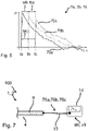
- Each of the at least three pressure sensors 5a, 5b, 5c is preferably set up to determine a transient pressure 7a, 7b, 7c acting on the respective pressure sensor surface 6 and to provide it as a pressure signal 70a, 70b, 70c.
- a schematic representation of determined pressure signals 70a, 70b, 70c is in Figure 5 shown.
- the at least three pressure signals 70a, 70b, 70c are used for further analysis of the physical properties of the shock wave 9.
- Each of the at least three pressure sensors 5a, 5b, 5c is particularly preferably set up to apply a transient pressure 7a, 7b, 7c acting on the respective pressure sensor surface 6 determine and in addition each of the at least three pressure sensors 5a, 5b, 5c is set up to determine an acceleration 8a, 8b, 8c of the respective pressure sensor 5a, 5b, 5c independently of the pressure 7a, 7b, 7c acting on the pressure sensor surface 6.
- the receiving element 1 has an electronics unit 11, as shown in FIG 6 shown.
- the electronics unit 11 is arranged in the measuring section 4 .
- the electronics unit 11 generates a difference between the determined transient pressure 7a, 7b, 7c and a proportion of the determined acceleration as a pressure signal 70a, 70b, 70c and provides the pressure signal 70a, 70b, 70c.
- This is advantageous since a pressure sensor 5a, 5b, 5c, which is exposed to a shock wave 9, is often accelerated.
- acceleration can act on a pressure transducer 5a, 5b, 5c, since individual components of the pressure transducer or the measuring element itself act as a seismic mass and exert a force on the measuring element during acceleration. An acceleration of the pressure sensor 5a, 5b, 5c can thus generate a signal which could be misinterpreted as a pressure signal 70a, 70b, 70c.
- the pressure sensor 5a, 5b, 5c is advantageously set up to detect an acceleration 8a, 8b, 8c and to compensate for a signal caused thereby.
- an electronics unit 11 is an electrically conductive connection between two conductors. Acceleration compensation of a pressure sensor and how it works is described, for example, in EP0902267A2 or WO06131015A2 described.
- the nose section 3 is designed to be largely rotationally symmetrical to the longitudinal axis X.
- a length of the nose section along the longitudinal axis X is at least three times greater than the largest diameter of the Nose section in a section perpendicular to the longitudinal axis X.
- the nose section 3 is according to FIG 1 and 3 made conical.
- the nose section 3 has a cross section in the form of an ogive in a section parallel to the longitudinal axis X, as shown in FIG 2 shown.
- This shape is known in the field of flying or floating bodies, which should have as little resistance as possible when moving through a fluid.
- the term ogive is understood to mean a pointed, streamlined body of revolution.
- the measuring section 4 is designed largely in the shape of a cylinder along the longitudinal axis X.
- the measuring section 4 thus adjoins the nose section 3 seamlessly and without any projections. This is advantageous since turbulence or distortion of the shock wave 9 can occur in the area of projections.
- the body 2 has a flat 12 .
- the flattening 12 has the shape of a chord 121, as in FIG figure 4 shown.
- the flat 12 is planar and extends at least partially along the longitudinal axis X and is spaced from the longitudinal axis X, as shown in FIG figure 2 shown.
- the respective pressure transducer surfaces 6 of the at least three pressure transducers 5a, 5b, 5c are arranged parallel to the flattening 12. This has the advantage that the body 2 does not have any projections in the area of the measuring section 3 . This is advantageous since turbulence or distortion of the shock wave 9 can occur in the area of projections.
- the pressure pickup surfaces 6 of the at least three pressure pickups 5a, 5b, 5c are level with the flattening.
- the pressure transducer surfaces 6 of the at least three pressure transducers 5a, 5b, 5c are arranged set back from the flattening 12 in the direction of the longitudinal axis X.
- the body 2 has no projections in the area of the measuring section 3 . This is advantageous since turbulence or distortion of the shock wave 9 can occur in the area of projections.
- moving the pressure-receiving surface back in the longitudinal X-axis direction provides protection of the pressure-receiving surface because the pressure-receiving surface is subjected to fewer shear forces in the longitudinal X-axis direction.
- the pressure-receiving surface is coated with a flexible protective layer.
- a flexible protective layer is, for example, a vinyl layer.
- the vinyl layer can be opaque. This is particularly advantageous when the pressure-receiving surface is designed as a thin-walled membrane. A thickness of less than 0.2 mm is understood to be thin-walled.
- the flexible protective layer protects the pressure measuring element located behind the membrane from environmental influences, such as excessive heat radiation. For example, if the shock wave is accompanied by an electromagnetic wave, for example in the infrared range, the electromagnetic wave can generate a signal in the pressure measuring element, which could be interpreted erroneously as a pressure signal. A flexible protective layer can minimize this problem.
- each of the at least three pressure sensors 5a, 5b, 5c has at least one piezoelectric pressure measuring element 17; which pressure measuring element 17 is in operative connection with the pressure pickup surface 6 .
- the pressure measuring element 17 is operatively connected to the pressure sensor surface when a pressure acting on the pressure sensor surface is transmitted to the pressure measuring element 17 and the pressure measuring element is thus set up to detect the pressure as a physical variable.
- Piezoelectric pressure sensing elements are made from piezoelectric materials.
- piezoelectric material is quartz, langasite (La 3 Ga 5 SiO 14 ), gallium orthophosphate (GaPO 4 ), lithium niobate (LiNbO 3 ), lithium tantalate (Li-TaO 3 ), berlinite (AlPO 4 ), topaz, tourmaline group minerals and lead titanate ( PbTiO3 ).
- quartz is particularly preferred. Quartz is robust and comparatively cheap. When a force acts on a surface, piezoelectric materials generate piezoelectric charges that can be detected as a charge signal in a charge amplifier.
- Piezoelectric materials are popular in measurement technology because they have a high natural frequency and can therefore also detect rapid changes in force up to the natural frequency of the crystal. They are therefore advantageous for fast processes, such as determining the transient pressure 7a, 7b, 7c of shock waves in fluids.
- a typical natural frequency of a pressure sensor 5a, 5b, 5c with a piezoelectric pressure measuring element 17 is up to 300 kHz.
- Each of the at least three pressure sensors 5a, 5b, 5c has at least one piezoelectric acceleration measuring element 15.
- the acceleration measuring element 15 is set up to determine an acceleration 8a, 8b, 8c of the pressure sensor 1 independently of the transient pressure 7a, 7b, 7c acting on the respective pressure sensor surface 6 .
- a signal of the pressure measuring element caused by an acceleration 8a, 8b, 8c can be compensated for.
- piezoelectric acceleration elements are characterized by the advantages described above.
- the nose section 3 is advantageously streamlined.
- the nose section 3 is set up to gradually compress a shock wave 9 impinging on the nose section 3 as it moves along the longitudinal axis X. FIG. As a result, distortions or turbulence of the shock wave 9 are advantageously avoided.
- the body 2 is made of a metal or a metal alloy. Metals and metal alloys have a high resistance. The receiving element 1 is therefore more resistant to damage from the shock wave 9.
- a receiving element 1 can also have the features of various described embodiments.
- the shape of the nose section 3 can easily be combined with the selection of the pressure measuring element.
- a recording element 1 is used to determine physical properties of a shock wave 9 .
- the longitudinal axis X of the receiving element 1 is aligned largely parallel to a propagation direction W of the shock wave 9 .
- the end of the nose section 31 points counter to the propagation direction W of the shock wave 9.
- the recording element 1 determines at least three transient pressures 7a, 7b, 7c and makes them available as a pressure signal 70a, 70b, 70c.
- Providing a signal is understood to mean that the provided signal is available for further use.
- Providing also includes storing the signal on an electronic memory and loading the signal from this memory.
- Providing also includes the possibility of displaying the signal on a display.
- a recording unit compares 14 the three provided pressure signals 70a, 70b, 70c.
- Recording unit 14 uses the time sequence (ta, tb, tc) of the at least three pressure signals 70a, 70b, 70c to determine at least one shock wave velocity v9 and provides this.
- a shock wave speed v9 ist is determined from the quotient of the distance covered and the time elapsed, with the distance between two pressure sensor surfaces 6 of two pressure sensors 5a, 5b, 5c and the elapsed time as the time difference of the shock wave front 91 determined at the corresponding pressure sensors 5a, 5b, 5c.
- a recording unit 14 is in 7 shown.
- the recording unit 14 uses the time sequence ta, tb, tc of the impingement of the shock wave front 91 on the at least three pressure sensors 5a.5b.5c to determine a shock wave acceleration a9. From the three pressure signals 70a, 70b, 70c, the shock wave acceleration a9 is determined and made available. First, the speed v9 of the shock wave 9 between a first pressure sensor 5a and a second pressure sensor 5b is determined as described above. Then the speed v9 of the shock wave is determined between a second pressure sensor 5b and a third pressure sensor 5c. The acceleration a9 of the shock wave 9 can be determined from the change in the two determined speeds v9. Acceleration a9 can be positive or negative. A negative acceleration a9 is known as deceleration.
- a pickup arrangement 100 comprises a pickup element 1, a cable 13 and a pickup unit 14.
- the cable 13 connects the pickup element 1 to the pickup unit 14 in an electrically conductive manner.
- Pressure signals 70a, 70b, 70c that are provided are transmitted from the receiving element 1 to the receiving unit 14 via the cable 13 .
- the recording element 1 is set up to detect the at least three pressure signals 70a, 70b, 70c.
- the recording unit 14 is also set up to compare the at least three pressure signals 70a, 70b, 70c.
- a method for determining physical properties of a shock wave 9 includes determining at least three transient pressures 7a, 7b, 7c as pressure signals 70a, 70b, 70c.
- the at least three transient pressure signals 70a, 70b, 70c are determined at positions Xa, Xb, Xc along the propagation direction W of the shock wave 9 at a distance from one another.
- the temporal position ta, tb, tc of a shock wave front 91 is determined from an increase in each pressure signal 70a, 70b, 70c.
- the time difference tab,tac,tbc between the at least three shock wave fronts is determined.
- the time difference tab,tac,tbc is the time difference between the impact of the shock wave front 91 on one of the three positions Xa,Xb,Xc and the impact of the shock wave front 91 on another of the three positions Xb,Xc,Xa.
- a speed v9 of the shock wave 9, also called shock wave speed v9, is determined from the time difference tab,tac,tbc between the at least three determined shock wave fronts 91.
- a shock wave acceleration a9 is determined from the time difference tab,tac,tbc between the at least three shock wave fronts 91.
- shock wave acceleration a9 and the shock wave velocity v9 together with the already known determination of the transient pressure enable a comprehensive characterization of the shock wave.
- the at least three pressure signals 70a, 70b, 70c are preferably determined and provided with a recording element 1.
- the longitudinal axis of the receiving element 1 is arranged parallel to a propagation direction W of the shock wave 9, as already described.
- the shock wave front 9 can be determined in various ways. In one embodiment of the method, the shock wave front 91 is determined at the point in time at which an increasing transient pressure 7a, 7b, 7c of the pressure signal 70a, 70b, 70c is half of the maximum pressure signal 70a, 70b, 70c. In a further embodiment of the method, the shock wave front 9 is determined at the point in time at which an increasing transient pressure 7a, 7b, 7c has a turning point. Both the speed v9 and the acceleration a9 of the shock wave 9 can be determined by means of both embodiments.
- the electronics unit 11 is as in 6 shown additionally designed as a charge amplifier. This has the advantage that piezoelectric charges do not have to be conducted to an external recording unit 14 via a cable 13 . When conducting electrical charges, there are high insulation requirements of at least 10 ⁇ 10 ohms for the cable 13. If the electronic unit 11 has a charge amplifier, a long cable can easily be selected. This simplifies a pickup arrangement 100 since the pickup unit 14 can be placed at a safe distance from the shock wave 9 .
- a pick-up element 1 is adapted to detect pressures of up to 1000 psi or about 69 bar.
- the receptacle 1 is designed to withstand pressures of up to 5000 psi or approximately 350 bar without damage.
Landscapes
- Physics & Mathematics (AREA)
- General Physics & Mathematics (AREA)
- Electromagnetism (AREA)
- Fluid Mechanics (AREA)
- Chemical & Material Sciences (AREA)
- Engineering & Computer Science (AREA)
- Combustion & Propulsion (AREA)
- Measuring Fluid Pressure (AREA)
Applications Claiming Priority (1)
| Application Number | Priority Date | Filing Date | Title |
|---|---|---|---|
| EP21179157 | 2021-06-11 |
Publications (2)
| Publication Number | Publication Date |
|---|---|
| EP4102202A2 true EP4102202A2 (fr) | 2022-12-14 |
| EP4102202A3 EP4102202A3 (fr) | 2023-01-18 |
Family
ID=76444272
Family Applications (1)
| Application Number | Title | Priority Date | Filing Date |
|---|---|---|---|
| EP22177140.5A Pending EP4102202A3 (fr) | 2021-06-11 | 2022-06-03 | Élément récepteur |
Country Status (3)
| Country | Link |
|---|---|
| US (1) | US12422289B2 (fr) |
| EP (1) | EP4102202A3 (fr) |
| CN (1) | CN115468700B (fr) |
Citations (3)
| Publication number | Priority date | Publication date | Assignee | Title |
|---|---|---|---|---|
| US2799788A (en) | 1954-11-16 | 1957-07-16 | James W Fitzgerald | Piezoelectric blast gages |
| EP0902267A2 (fr) | 1997-09-15 | 1999-03-17 | K.K. Holding Ag | Capteur de pression à compensation des effets d'accélération |
| WO2006131015A2 (fr) | 2005-06-10 | 2006-12-14 | Kistler Holding Ag | Capteur de pression a compensation d'acceleration active et passive |
Family Cites Families (15)
| Publication number | Priority date | Publication date | Assignee | Title |
|---|---|---|---|---|
| US3290645A (en) * | 1964-02-13 | 1966-12-06 | Whitehall Electronics Corp | Method and underwater streamer apparatus for improving the fidelity of recorded seismic signals |
| US4932003A (en) | 1982-05-19 | 1990-06-05 | Exxon Production Research Company | Acoustic quadrupole shear wave logging device |
| DE3584722D1 (de) * | 1984-12-28 | 1992-01-02 | Schlumberger Ltd | Verfahren und vorrichtung zur untersuchung in einem bohrloch mit akustischen dipolscherwellen. |
| US5349853A (en) * | 1992-12-30 | 1994-09-27 | Oehler Kenneth L | Apparatus and method for measuring and calculating exterior and interior ballistics |
| RU2130597C1 (ru) * | 1996-10-01 | 1999-05-20 | Селетков Сергей Григорьевич | Устройство и способ селеткова для определения давления и скорости движения ударных волн, скорости звука в среде их распространения и направления на звуковой источник |
| RU2262088C2 (ru) * | 2002-08-26 | 2005-10-10 | Российский федеральный ядерный центр - Всероссийский научно-исследовательский институт экспериментальной физики - РФЯЦ-ВНИИЭФ | Датчик ударных волн |
| GB2428089B (en) * | 2005-07-05 | 2008-11-05 | Schlumberger Holdings | Borehole seismic acquisition system using pressure gradient sensors |
| CN202339240U (zh) | 2011-10-26 | 2012-07-18 | 北京理工北阳爆破工程技术有限责任公司 | 多点式压电压力传感器 |
| CN102854335A (zh) | 2012-09-20 | 2013-01-02 | 西北工业大学 | 一种弹丸速度及加速度的测量方法及装置 |
| CN104406728A (zh) * | 2014-11-25 | 2015-03-11 | 北京理工大学 | 测量水下爆炸近场冲击波压力的锰铜压力传感器及装置 |
| CN105758576B (zh) | 2016-03-01 | 2019-03-12 | 北京理工大学 | 一种双敏感元件笔杆式自由场压力传感器 |
| CN108061812B (zh) | 2017-12-01 | 2023-07-14 | 西安工业大学 | 一种弹丸速度的激光测速系统及其方法 |
| CN110672241B (zh) * | 2019-09-02 | 2022-03-22 | 南京理工大学 | 一种冲击波压力传感器 |
| CN111307343B (zh) | 2019-11-21 | 2021-07-30 | 中北大学 | 一种消除压力传感器加速度效应和温度效应的装置 |
| CN112254591B (zh) | 2020-10-21 | 2021-09-07 | 中国科学院力学研究所 | 一种气体爆轰驱动超高速发射的测试装置 |
-
2022
- 2022-06-03 EP EP22177140.5A patent/EP4102202A3/fr active Pending
- 2022-06-08 US US17/835,151 patent/US12422289B2/en active Active
- 2022-06-10 CN CN202210655860.3A patent/CN115468700B/zh active Active
Patent Citations (3)
| Publication number | Priority date | Publication date | Assignee | Title |
|---|---|---|---|---|
| US2799788A (en) | 1954-11-16 | 1957-07-16 | James W Fitzgerald | Piezoelectric blast gages |
| EP0902267A2 (fr) | 1997-09-15 | 1999-03-17 | K.K. Holding Ag | Capteur de pression à compensation des effets d'accélération |
| WO2006131015A2 (fr) | 2005-06-10 | 2006-12-14 | Kistler Holding Ag | Capteur de pression a compensation d'acceleration active et passive |
Also Published As
| Publication number | Publication date |
|---|---|
| US12422289B2 (en) | 2025-09-23 |
| CN115468700B (zh) | 2025-09-12 |
| CN115468700A (zh) | 2022-12-13 |
| EP4102202A3 (fr) | 2023-01-18 |
| US20220397436A1 (en) | 2022-12-15 |
Similar Documents
| Publication | Publication Date | Title |
|---|---|---|
| EP0065511A1 (fr) | Instrument de mesure avec un élément de détection piézoélectrique | |
| DE102007014161B4 (de) | Vorrichtung und Verfahren zur Lastmessung an Lagern von Bauwerken | |
| EP1608939B1 (fr) | Dispositif permettant de determiner et/ou de surveiller le debit volumetrique et/ou massique d'un milieu | |
| DE102015110711A1 (de) | MEMS Sensor zu Messung mindestens einer Messgröße eines strömenden Fluids | |
| DE60129966T2 (de) | Kollisionsprüfungsvorrichtung | |
| EP2546616A1 (fr) | Appareil de mesure de débit à vortex, capteur de pression pour appareil de mesure de débit à vortex et procédé de fabrication dýun tel capteur de pression | |
| DE2145198C3 (de) | Druckrezeptor | |
| EP2554964A2 (fr) | Dispositif de mesure de la pression et de la température | |
| DE3729409C2 (fr) | ||
| EP4177575A1 (fr) | Détection de pression au moyen d'un transducteur ultrasonore piézocéramique | |
| DE102020100675A1 (de) | Kapazitiver Drucksensor mit Temperaturerfassung | |
| DE2231491C3 (de) | Druckmeßumformer | |
| DE102016011256A1 (de) | Verfahren zur Durchflussbestimmung eines strömenden Mediums | |
| DE3719842A1 (de) | Druckmesseinrichtung | |
| Chalupnik et al. | Dynamic deformation of metals under high hydrostatic pressure: Authors describe a method that can be used to investigate the static and dynamic behavior of materials subjected to hydrostatic confining pressures in the range of zero to 100,000 psi | |
| EP3196601B1 (fr) | Convertisseur d'ultrasons | |
| DE19605923C2 (de) | Durchflußmesser | |
| CH387980A (de) | Druckimpulsmessvorrichtung | |
| DE102011081544A1 (de) | Messverfahren und Messvorrichtung zur Druckbestimmung von Flüssigkeiten | |
| DE3130363C2 (fr) | ||
| CN115468700B (zh) | 传感元件 | |
| DE102023203256B4 (de) | Messsonde | |
| DE102005051785A1 (de) | Vorrichtung und Verfahren zur verwirbelungsfreien Messung der Flussgeschwindigkeit und/oder Durchflussmenge eines Fluids | |
| DE19861186B4 (de) | Duchflussmessvorrichtung | |
| DE102016109520A1 (de) | Verfahren und Vorrichtung zur Ermittlung einer Kenngröße für die Auswirkung von Kavitationen |
Legal Events
| Date | Code | Title | Description |
|---|---|---|---|
| PUAI | Public reference made under article 153(3) epc to a published international application that has entered the european phase |
Free format text: ORIGINAL CODE: 0009012 |
|
| STAA | Information on the status of an ep patent application or granted ep patent |
Free format text: STATUS: THE APPLICATION HAS BEEN PUBLISHED |
|
| AK | Designated contracting states |
Kind code of ref document: A2 Designated state(s): AL AT BE BG CH CY CZ DE DK EE ES FI FR GB GR HR HU IE IS IT LI LT LU LV MC MK MT NL NO PL PT RO RS SE SI SK SM TR |
|
| PUAL | Search report despatched |
Free format text: ORIGINAL CODE: 0009013 |
|
| AK | Designated contracting states |
Kind code of ref document: A3 Designated state(s): AL AT BE BG CH CY CZ DE DK EE ES FI FR GB GR HR HU IE IS IT LI LT LU LV MC MK MT NL NO PL PT RO RS SE SI SK SM TR |
|
| RIC1 | Information provided on ipc code assigned before grant |
Ipc: G01V 1/00 20060101ALI20221215BHEP Ipc: G01L 23/10 20060101AFI20221215BHEP |
|
| STAA | Information on the status of an ep patent application or granted ep patent |
Free format text: STATUS: REQUEST FOR EXAMINATION WAS MADE |
|
| 17P | Request for examination filed |
Effective date: 20230623 |
|
| RBV | Designated contracting states (corrected) |
Designated state(s): AL AT BE BG CH CY CZ DE DK EE ES FI FR GB GR HR HU IE IS IT LI LT LU LV MC MK MT NL NO PL PT RO RS SE SI SK SM TR |
|
| STAA | Information on the status of an ep patent application or granted ep patent |
Free format text: STATUS: EXAMINATION IS IN PROGRESS |
|
| 17Q | First examination report despatched |
Effective date: 20231214 |