EP4102486A2 - Procédé de commande d'un mouvement de vol d'un aéronef, ainsi qu'aéronef - Google Patents
Procédé de commande d'un mouvement de vol d'un aéronef, ainsi qu'aéronef Download PDFInfo
- Publication number
- EP4102486A2 EP4102486A2 EP22176484.8A EP22176484A EP4102486A2 EP 4102486 A2 EP4102486 A2 EP 4102486A2 EP 22176484 A EP22176484 A EP 22176484A EP 4102486 A2 EP4102486 A2 EP 4102486A2
- Authority
- EP
- European Patent Office
- Prior art keywords
- aircraft
- flight
- image
- camera
- image data
- Prior art date
- Legal status (The legal status is an assumption and is not a legal conclusion. Google has not performed a legal analysis and makes no representation as to the accuracy of the status listed.)
- Granted
Links
Images

Classifications
-
- G—PHYSICS
- G08—SIGNALLING
- G08G—TRAFFIC CONTROL SYSTEMS
- G08G5/00—Traffic control systems for aircraft
- G08G5/80—Anti-collision systems
-
- G—PHYSICS
- G05—CONTROLLING; REGULATING
- G05D—SYSTEMS FOR CONTROLLING OR REGULATING NON-ELECTRIC VARIABLES
- G05D1/00—Control of position, course, altitude or attitude of land, water, air or space vehicles, e.g. using automatic pilots
- G05D1/10—Simultaneous control of position or course in three dimensions
- G05D1/101—Simultaneous control of position or course in three dimensions specially adapted for aircraft
- G05D1/106—Change initiated in response to external conditions, e.g. avoidance of elevated terrain or of no-fly zones
-
- G—PHYSICS
- G05—CONTROLLING; REGULATING
- G05D—SYSTEMS FOR CONTROLLING OR REGULATING NON-ELECTRIC VARIABLES
- G05D1/00—Control of position, course, altitude or attitude of land, water, air or space vehicles, e.g. using automatic pilots
- G05D1/0094—Control of position, course, altitude or attitude of land, water, air or space vehicles, e.g. using automatic pilots involving pointing a payload, e.g. camera, weapon, sensor, towards a fixed or moving target
-
- G—PHYSICS
- G05—CONTROLLING; REGULATING
- G05D—SYSTEMS FOR CONTROLLING OR REGULATING NON-ELECTRIC VARIABLES
- G05D1/00—Control of position, course, altitude or attitude of land, water, air or space vehicles, e.g. using automatic pilots
- G05D1/60—Intended control result
- G05D1/617—Safety or protection, e.g. defining protection zones around obstacles or avoiding hazards
- G05D1/621—Safety or protection, e.g. defining protection zones around obstacles or avoiding hazards responding to weather conditions, e.g. storms or wind shear
-
- G—PHYSICS
- G05—CONTROLLING; REGULATING
- G05D—SYSTEMS FOR CONTROLLING OR REGULATING NON-ELECTRIC VARIABLES
- G05D1/00—Control of position, course, altitude or attitude of land, water, air or space vehicles, e.g. using automatic pilots
- G05D1/60—Intended control result
- G05D1/656—Interaction with payloads or external entities
- G05D1/689—Pointing payloads towards fixed or moving targets
-
- G—PHYSICS
- G06—COMPUTING OR CALCULATING; COUNTING
- G06T—IMAGE DATA PROCESSING OR GENERATION, IN GENERAL
- G06T7/00—Image analysis
- G06T7/70—Determining position or orientation of objects or cameras
- G06T7/73—Determining position or orientation of objects or cameras using feature-based methods
-
- G—PHYSICS
- G08—SIGNALLING
- G08G—TRAFFIC CONTROL SYSTEMS
- G08G5/00—Traffic control systems for aircraft
- G08G5/20—Arrangements for acquiring, generating, sharing or displaying traffic information
- G08G5/21—Arrangements for acquiring, generating, sharing or displaying traffic information located onboard the aircraft
-
- G—PHYSICS
- G08—SIGNALLING
- G08G—TRAFFIC CONTROL SYSTEMS
- G08G5/00—Traffic control systems for aircraft
- G08G5/50—Navigation or guidance aids
- G08G5/55—Navigation or guidance aids for a single aircraft
-
- G—PHYSICS
- G08—SIGNALLING
- G08G—TRAFFIC CONTROL SYSTEMS
- G08G5/00—Traffic control systems for aircraft
- G08G5/70—Arrangements for monitoring traffic-related situations or conditions
- G08G5/72—Arrangements for monitoring traffic-related situations or conditions for monitoring traffic
- G08G5/723—Arrangements for monitoring traffic-related situations or conditions for monitoring traffic from the aircraft
-
- B—PERFORMING OPERATIONS; TRANSPORTING
- B64—AIRCRAFT; AVIATION; COSMONAUTICS
- B64U—UNMANNED AERIAL VEHICLES [UAV]; EQUIPMENT THEREFOR
- B64U2101/00—UAVs specially adapted for particular uses or applications
- B64U2101/30—UAVs specially adapted for particular uses or applications for imaging, photography or videography
-
- B—PERFORMING OPERATIONS; TRANSPORTING
- B64—AIRCRAFT; AVIATION; COSMONAUTICS
- B64U—UNMANNED AERIAL VEHICLES [UAV]; EQUIPMENT THEREFOR
- B64U2201/00—UAVs characterised by their flight controls
- B64U2201/10—UAVs characterised by their flight controls autonomous, i.e. by navigating independently from ground or air stations, e.g. by using inertial navigation systems [INS]
-
- G—PHYSICS
- G06—COMPUTING OR CALCULATING; COUNTING
- G06T—IMAGE DATA PROCESSING OR GENERATION, IN GENERAL
- G06T2207/00—Indexing scheme for image analysis or image enhancement
- G06T2207/10—Image acquisition modality
- G06T2207/10032—Satellite or aerial image; Remote sensing
-
- G—PHYSICS
- G06—COMPUTING OR CALCULATING; COUNTING
- G06T—IMAGE DATA PROCESSING OR GENERATION, IN GENERAL
- G06T2207/00—Indexing scheme for image analysis or image enhancement
- G06T2207/20—Special algorithmic details
- G06T2207/20084—Artificial neural networks [ANN]
-
- G—PHYSICS
- G06—COMPUTING OR CALCULATING; COUNTING
- G06T—IMAGE DATA PROCESSING OR GENERATION, IN GENERAL
- G06T2207/00—Indexing scheme for image analysis or image enhancement
- G06T2207/30—Subject of image; Context of image processing
- G06T2207/30248—Vehicle exterior or interior
- G06T2207/30252—Vehicle exterior; Vicinity of vehicle
- G06T2207/30261—Obstacle
-
- G—PHYSICS
- G08—SIGNALLING
- G08G—TRAFFIC CONTROL SYSTEMS
- G08G5/00—Traffic control systems for aircraft
- G08G5/50—Navigation or guidance aids
- G08G5/57—Navigation or guidance aids for unmanned aircraft
Definitions
- the invention relates to a method for controlling a flight movement of an aircraft and an aircraft.
- Aircraft are known as both manned and unmanned aircraft.
- the flight movement of the aircraft is controlled with the aid of a control device which provides control signals in order to control drive devices and rudders, for example.
- a control device which provides control signals in order to control drive devices and rudders, for example.
- it is known, when determining the control signals for the flight movement of the aircraft to take into account sensor signals from a sensor device which indicate environmental parameters for the area surrounding the aircraft, and to carry out the flight movement as a function of such sensor signals.
- the object of the invention is to specify a method for controlling a flight movement of an aircraft and an aircraft that enable efficient and safe control of the flight movement.
- a method for controlling a flight movement of an aircraft which has the following: Acquisition of first image data by means of a first camera device, which is arranged on an aircraft and set up to observe an environment of the aircraft when flying, the first image data display first series of first camera images; Acquisition of second image data by means of a second camera device, which is arranged on an aircraft and set up to observe the surroundings of the aircraft when flying, the first image data displaying a second sequence of second camera images; and processing the first and second image data by means of an evaluation device, the following being provided: pre-processing of the first and second image data, measurement image data displaying at least one camera measurement image being determined from the first and second image data; Running a redundant image analysis for the at least one camera measurement image, wherein the at least a camera measurement image is analyzed in separate image analyzes using a first image analysis based on artificial intelligence and a second image analysis that is carried out without artificial intelligence; determining object parameters for a location of a flight obstacle in the vicinity of the aircraft if the first image
- an aircraft which has the following: a sensor device which has a first and a second camera device; an evaluation device which has one or more processors; and a control device that is set up to control a flight movement of the aircraft.
- the aircraft is set up for the following: capturing first image data using a first camera device, which is arranged on an aircraft and set up to observe an environment of the aircraft when flying, the first image data displaying a first sequence of first camera images; Acquisition of second image data by means of a second camera device, which is arranged on an aircraft and set up to observe the surroundings of the aircraft when flying, the first image data displaying a second sequence of second camera images; and processing the first and second image data by means of an evaluation device, the following being provided: pre-processing of the first and second image data, measurement image data displaying at least one camera measurement image being determined from the first and second image data; Carrying out a redundant image analysis for the at least one camera measurement image, the at least one camera measurement image being analyzed in separate image analyzes using a
- the proposed technology provides for several camera devices in the aircraft, which capture respective image data for the environment of the aircraft during the flight movement, with the image data each displaying a sequence of camera images.
- a redundant image analysis is provided for the evaluation of the image data by means of the evaluation device, which works with an image analysis based on artificial intelligence and an image analysis not based on artificial intelligence (free of it), so that independent image analyzes are used to check whether the captured image data represents a flight obstacle for show the flight movement of the aircraft.
- Object parameters are determined for the location of such a flight obstacle if the image analysis not based on artificial intelligence confirms a result of the image analysis based on artificial intelligence to the effect that the analyzed image data indicate at least one flight obstacle.
- the redundant image analysis for the previously recorded image data with the two image analyzes carried out independently of one another increases the security for a correct determination of flight obstacles and the subsequent collision avoidance.
- Both an image analysis based on artificial intelligence and a classic image analysis are used independently of one another for the evaluation of the image data recorded with a plurality of camera devices.
- At least one object parameter from the following group can be determined: distance of the flight obstacle from the aircraft, direction of the flight obstacle in relation to the aircraft, size of the flight obstacle, moving flight obstacle, stationary flight obstacle, orientation of a flight movement of the flight obstacle, current Speed of flight movement of the flight obstacle and a predicted flight path of the flight obstacle for a forecast period.
- Determining the object parameters can also include the following: the control device providing flight movement data which indicate the flight movement of the aircraft; and determining the object parameters for the location of the flight obstacle in the area surrounding the aircraft, taking into account the flight movement data.
- the flight movement data can in particular characterize a current flight movement of the aircraft, for example with regard to speed and/or direction in space. The consideration the flight movement data optimizes the determination of the object parameters for the flight obstacle to avoid a collision by determining them as a function of or taking into account the flight movement data.
- a movement for the flight obstacle can be determined by means of an optical flow.
- An optical flow shows, for example, a movement path for one or more image pixels in the at least one camera measurement image and can thus show a movement for any image pixels assigned to a flight obstacle, which is an indication of the flight obstacle that is moving.
- an optical flow of an image sequence is understood to be a vector field of a speed of one or more image pixels projected into the image plane in the observed space (environment). The optical flow is thus a representation of movement information in the context of image analysis.
- one or more of the following characteristic values for the flight obstacle can be determined using an analysis algorithm based on artificial intelligence: height of the flight obstacle, width of the flight obstacle and confidence value for determining the flying object in the at least one camera measurement image.
- an analysis algorithm based on artificial intelligence it can be provided that a frame or a box around the flight obstacle in the at least one camera measurement image is determined by means of the analysis algorithm used, whereby an image area of the at least one camera measurement image is determined in which the flight obstacle is present with a certain probability is.
- the frame can be determined in such a way that it shows the outer limits of the flight obstacle in the at least one camera measurement image, from which the height and/or width of the flight obstacle can be determined.
- a neural network can be used in the image analysis using the analysis algorithm based on artificial intelligence, for example in combination with a determination of an optical flow using the analysis algorithm not based on artificial intelligence.
- the previously trained neural network processes the image data directly in the image analysis based on artificial intelligence.
- Various layers of the neural network can be run through until characteristic values in image coordinates (pixel coordinates, frame size, object class and confidence value) are ultimately estimated directly.
- the object parameters such as the distance of the flight obstacle from the aircraft, the direction of the flight obstacle in relation to the aircraft, and the size of the aircraft can be determined using the camera parameters (calibration) from the characteristic values of the neural network and the specific object class.
- edge filters such as Sobel filters through to optical flow methods that are based on simple geometric methods can be used as methods that are not based on artificial intelligence.
- a three-dimensional movement path for the flight obstacle in the surrounding area can be determined from positions of the flight obstacle that follow one another over time, for example the flight of another aircraft.
- Execution of a visual analysis for the first/second camera device during the pre-processing of the first and the second image data it being determined here whether a respective detection field of view (camera field of view) of the first/second camera device is free of a field of view blockage. In this way it is ensured that the detection or detection field of view for the camera devices is not blocked in each case, so that the image data is detected with sufficient certainty in order to then carry out an image analysis that satisfies the security requirements.
- the control device receives information about whether and, if so, to what extent the detection field of view of one or more camera devices is blocked, for example due to dirt.
- Safety measures can then be taken. For example, provision can be made to exclude the image data from the image data analysis from a camera device whose detection field of view is partially blocked.
- the control device can check the field of view characteristics and control the flight movement of the aircraft emergency landing control signals accordingly if the field of view characteristics indicate an extent of blockage of the detection field of view for the first camera device and/or the second camera device, which exceeds a threshold value, the emergency landing control signals being set up to indicate an emergency landing of the to effect aircraft.
- exceeding the threshold indicates a situation in which a safe controller of the flight movement is potentially no longer given based on the captured image data, which is why the emergency landing is initiated.
- the configurations explained above in connection with the method for controlling the flight movement of the aircraft can be provided accordingly in connection with the aircraft.
- the aircraft can be a manned or unmanned aircraft.
- the camera device and the evaluation device can be accommodated together in a sensor module or device, which is mounted on the aircraft as a detachable overall unit.
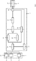
- FIG. 1 shows a schematic representation of an arrangement of functional components for use in controlling a flight movement of an aircraft with a sensor device 1 and an evaluation device 2, which is set up to evaluate image data captured by the sensor device 1 in order to determine object parameters for a stationary (not moving) or a moving object to determine a moving, for example flying flight obstacle, so that based on this a control device 3 of the aircraft can control the flight movement of the aircraft in such a way that a collision with the flight obstacle is avoided, for example with other aircraft in the airspace, but also with stationary flight obstacles on the ground arranged, such as chimneys or towers.
- the sensor device 1 comprises according to 2 several camera devices 1.1, . . . , 1.n, each of which is set up to observe the surroundings of the aircraft during its flight movement and to capture the respective image data that display a sequence of camera images.
- the camera devices 1.1, ..., 1.n can, for example, one or more of the following camera types: thermal imaging camera, visual camera, infrared camera, multispectral camera and event-based camera (event camera).
- the event camera uses neuromorphic visual sensors. Instead of delivering an image sequence with a constant frequency (photographic camera), event cameras (only) send information from the pixels (image data) where the brightness has changed significantly. Such pixel-by-pixel changes are also referred to as events, which are provided with a time stamp with microsecond precision and are then immediately transmitted asynchronously. Since only non-redundant information is transmitted, event cameras are energy-efficient and able to capture very fast movements. In doing so, they directly tackle the trade-off between energy requirements and latency. In addition, event cameras can be used that have a dynamic range of around 140 dB, for example (compared to standard cameras with typically around 60 dB), because each pixel is independent.
- the image data recorded in a step 20 are transmitted from the sensor device 1 to the evaluation device 2, where the camera images are processed.
- the image data is pre-processed (step 21).
- measurement image data are determined from the image data, which display at least one camera measurement image. This means that a fusion of the different image data (camera images) is carried out.
- Raw data are combined to form the at least one camera measurement image. Provision can be made for multiple camera measurement images to be generated from the image data.
- the evaluation device 2 carries out a redundant image analysis for the measured image data, which display the at least one camera image, by means of further data processing.
- a first image analysis step 22
- the at least one camera measurement image is analyzed using an analysis algorithm based on artificial intelligence.
- the image analysis is carried out using a neural network, for example a CNN ( “Convolutional Neural Network” ) or a visual transformer.
- a neural network for example a CNN ( “Convolutional Neural Network” ) or a visual transformer.
- the pixel data are processed directly as RGB values by the neural network and changed using different layers.
- the output of the neural network is directly the characteristic values in image coordinates.
- the neural network was previously trained using training data.
- the at least one camera measurement image is analyzed in a second image analysis (step 23), the second image analysis being carried out using a classic analysis algorithm which is free of artificial intelligence.
- Both image analyzes carried out independently of one another for the at least one camera measurement image serve to check whether the at least one camera measurement image indicates a flight obstacle for the aircraft, so that there is a potential risk of collision.
- step 24 the results of the two image analyzes are combined.
- a subsequent determination of object parameters for the flight obstacle (step 25) only takes place if, when the results of the image analyzes are combined, it is determined that a flight obstacle predicted by the second image analysis (based on artificial intelligence) is also predicted by the first image analysis (not based on artificial intelligence). Intelligence-based) image analysis is determined. Only if the second image analysis confirms the result of the first image analysis, to the effect that the existence of a flight obstacle is determined in the at least one camera measurement image, are object parameters then determined for the flight obstacle, which indicate a location of the flight obstacle in the vicinity of the aircraft.
- the object parameters for the flight obstacle can include one or more of the following parameters: distance of the flight obstacle to the aircraft, direction of the flight obstacle in relation to the aircraft, moving/still flight obstacle and orientation of a flight movement of the flight obstacle.
- a three-dimensional movement path for the flight obstacle in the vicinity of the aircraft can also be determined if the redundant image analysis reveals the existence of the flight obstacle in the captured image data.
- step 27 The object parameters for the flight obstacle are then provided and transmitted at an interface in step 26 for transmission to the control device 3 of the aircraft, whereupon the aircraft is controlled by the control device 3 in a collision-avoiding manner (step 27).
- step 27 is optionally provided in the exemplary embodiment shown, before determining the object parameters and/or before transmitting the object parameters to the control device 3, a visual analysis for one or more of the camera devices 1.1, . .., 1.n to perform.
- the view analysis it is checked whether a respectively assigned detection field of view of the camera devices 1.1, ..., 1.n is possibly at least partially blocked. If the detection field of view is blocked, the associated camera device may no longer be able to reliably fulfill its sensor task.
- field of view characteristics are generated and transmitted to the control device 3, the field of view characteristics indicating whether and, if so, to what extent the detection field of view of one or more of the camera devices 1.1, . . . , 1.n is blocked. If the extent of a blockage for at least one detection field of view exceeds a threshold value, the control device 3 can initiate an emergency landing of the aircraft.
- a system status e.g. power supply and/or utilization of a processor unit
- the current runtime of the artificial intelligence and/or a time synchronization of the camera devices 1.1, ..., 1.n are continuously monitored, whether individually or in groups, e.g regular time intervals.
- control device 3 Based on the object parameters received from the evaluation device 2, the control device 3 then controls the aircraft in such a way that a collision with the detected obstacle to flight is avoided.
Landscapes
- Engineering & Computer Science (AREA)
- Physics & Mathematics (AREA)
- General Physics & Mathematics (AREA)
- Aviation & Aerospace Engineering (AREA)
- Radar, Positioning & Navigation (AREA)
- Remote Sensing (AREA)
- Automation & Control Theory (AREA)
- Computer Vision & Pattern Recognition (AREA)
- Theoretical Computer Science (AREA)
- Traffic Control Systems (AREA)
Applications Claiming Priority (1)
| Application Number | Priority Date | Filing Date | Title |
|---|---|---|---|
| DE102021115139.2A DE102021115139B4 (de) | 2021-06-11 | 2021-06-11 | Verfahren zum Steuern einer Flugbewegung eines Fluggeräts sowie Fluggerät |
Publications (4)
| Publication Number | Publication Date |
|---|---|
| EP4102486A2 true EP4102486A2 (fr) | 2022-12-14 |
| EP4102486A3 EP4102486A3 (fr) | 2023-01-25 |
| EP4102486C0 EP4102486C0 (fr) | 2025-04-16 |
| EP4102486B1 EP4102486B1 (fr) | 2025-04-16 |
Family
ID=81878023
Family Applications (1)
| Application Number | Title | Priority Date | Filing Date |
|---|---|---|---|
| EP22176484.8A Active EP4102486B1 (fr) | 2021-06-11 | 2022-05-31 | Procédé de commande d'un mouvement de vol d'un aéronef, ainsi qu'aéronef |
Country Status (3)
| Country | Link |
|---|---|
| US (1) | US12197235B2 (fr) |
| EP (1) | EP4102486B1 (fr) |
| DE (1) | DE102021115139B4 (fr) |
Cited By (1)
| Publication number | Priority date | Publication date | Assignee | Title |
|---|---|---|---|---|
| US20250349218A1 (en) * | 2024-05-09 | 2025-11-13 | Honeywell International Inc. | System and method for autonomous taxiing |
Families Citing this family (2)
| Publication number | Priority date | Publication date | Assignee | Title |
|---|---|---|---|---|
| US12406348B2 (en) * | 2023-06-16 | 2025-09-02 | Rtx Corporation | Neuromorphic foreign object detection |
| DE102024103085A1 (de) | 2024-02-05 | 2025-08-07 | Rheinmetall Electronics Gmbh | Kamera-Vorrichtung mit Bildstabilisierung, Plattform mit Kamera-Vorrichtung und Verfahren zum Betreiben einer Kamera-Vorrichtung |
Family Cites Families (12)
| Publication number | Priority date | Publication date | Assignee | Title |
|---|---|---|---|---|
| GB9325243D0 (en) * | 1993-12-09 | 1994-02-09 | New Royal Holloway & Bedford | Automatic monitoring system |
| US7061401B2 (en) * | 2003-08-07 | 2006-06-13 | BODENSEEWERK GERäTETECHNIK GMBH | Method and apparatus for detecting a flight obstacle |
| WO2018081952A1 (fr) | 2016-11-02 | 2018-05-11 | SZ DJI Technology Co., Ltd. | Systèmes et procédés de commande de hauteur d'un objet mobile |
| US20180290748A1 (en) | 2017-04-03 | 2018-10-11 | Versatol, Llc | Autonomous in-tunnel intelligence, surveillance, and reconnaissance drone |
| US10600295B2 (en) | 2017-05-05 | 2020-03-24 | Tg-17, Inc. | System and method for threat monitoring, detection, and response |
| US10534362B2 (en) | 2017-08-17 | 2020-01-14 | International Business Machines Corporation | Drone captcha |
| US20190068829A1 (en) * | 2017-08-24 | 2019-02-28 | Qualcomm Incorporated | Systems and Methods for Improving Performance of a Robotic Vehicle by Managing On-board Camera Obstructions |
| US10402646B2 (en) * | 2017-09-21 | 2019-09-03 | Amazon Technologies, Inc. | Object detection and avoidance for aerial vehicles |
| WO2019152312A1 (fr) | 2018-01-31 | 2019-08-08 | Walmart Apollo, Llc | Système et procédé de prise de décision autonome, d'action corrective et de navigation dans un monde à changement dynamique |
| CN113411492B (zh) * | 2018-12-26 | 2023-04-07 | 深圳市道通智能航空技术股份有限公司 | 一种图像处理方法、装置和无人机 |
| US11409291B2 (en) | 2019-03-21 | 2022-08-09 | Performance Drone Works Llc | Modular autonomous drone |
| CN110796104B (zh) * | 2019-11-01 | 2025-07-15 | 深圳市道通智能航空技术股份有限公司 | 目标检测方法、装置、存储介质及无人机 |
-
2021
- 2021-06-11 DE DE102021115139.2A patent/DE102021115139B4/de active Active
-
2022
- 2022-05-31 EP EP22176484.8A patent/EP4102486B1/fr active Active
- 2022-06-10 US US17/837,939 patent/US12197235B2/en active Active
Cited By (1)
| Publication number | Priority date | Publication date | Assignee | Title |
|---|---|---|---|---|
| US20250349218A1 (en) * | 2024-05-09 | 2025-11-13 | Honeywell International Inc. | System and method for autonomous taxiing |
Also Published As
| Publication number | Publication date |
|---|---|
| US12197235B2 (en) | 2025-01-14 |
| DE102021115139B4 (de) | 2023-01-19 |
| EP4102486A3 (fr) | 2023-01-25 |
| DE102021115139A1 (de) | 2022-12-15 |
| US20220397919A1 (en) | 2022-12-15 |
| EP4102486C0 (fr) | 2025-04-16 |
| EP4102486B1 (fr) | 2025-04-16 |
Similar Documents
| Publication | Publication Date | Title |
|---|---|---|
| EP3466239B1 (fr) | Procédé de fonctionnement d'un engin agricole automatique | |
| EP4102486A2 (fr) | Procédé de commande d'un mouvement de vol d'un aéronef, ainsi qu'aéronef | |
| DE102010038341B4 (de) | Videoüberwachungssystem sowie Verfahren zur Konfiguration eines Videoüberwachungssystems | |
| DE102009015142B4 (de) | Fahrzeugumgebungs-Erkennungs-Vorrichtung und Steuerungssystem zum Verfolgen eines vorausfahrenden Fahrzeugs | |
| EP3977430B1 (fr) | Procédé et dispositif de détection de fumée | |
| DE102018103803B4 (de) | System für das erkennen einer fehlerhaften sensorinstallation innerhalb eines fahrzeugs, um die mit der objekterkennung verbundenen gefahren zu verringern | |
| EP3181421A1 (fr) | Procédé et système de commande automatique d'un véhicule suiveur à l'aide d'un véhicule meneur | |
| WO2019081135A1 (fr) | Dispositif de surveillance, équipement industriel, procédé de surveillance et programme informatique | |
| DE102019212842B4 (de) | Steuerung eines Kraftfahrzeugs unter Verwendung einer unbemannten Flugvorrichtung | |
| DE102009016819A1 (de) | Verfahren zur Detektion wenigstens eines Objekts und/oder wenigstens einer Objektgruppe, Computerprogramm, Computerprogammprodukt, Stereokameraeinrichtung, aktiv Strahlung aussendendes Bildsensorsystem und Überwachungsvorrichtung | |
| EP4244829B1 (fr) | Procédé de détection d'un environnement d'un premier système de capteur | |
| DE102012215465A1 (de) | Verfahren und Informationssystem zum Filtern von Objektinformationen | |
| WO2020126447A1 (fr) | Procédé et système de fourniture de données d'environnement | |
| EP3803679B1 (fr) | Procédé d'assistance au fonctionnement, unité de commande, système d'assistance au fonctionnement et dispositif de travail | |
| EP4500488A1 (fr) | Système de surveillance comprenant un détecteur de personne | |
| DE102018101162B4 (de) | Messsystem und Verfahren zur extrinsischen Kalibrierung | |
| DE102019127826B4 (de) | Sicherer optoelektronischer Sensor und Verfahren zum Absichern eines Überwachungsbereichs | |
| DE102016212716A1 (de) | Steuervorrichtung und verfahren | |
| DE102018121866A1 (de) | Verfahren zur Tiefenabschätzung von zweidimensionalen Sensordaten | |
| DE102021115140B4 (de) | Verfahren zum Steuern einer Flugbewegung eines Fluggeräts zum Landen oder zum Abwerfen einer Ladung sowie Fluggerät | |
| EP4145238B1 (fr) | Procédé de commande d'un véhicule aérien sans pilote pour un vol d'inspection servant à inspecter un objet et véhicule aérien d'inspection sans pilote | |
| DE102023005203A1 (de) | Verfahren zur Sensorfusion | |
| EP4246268B1 (fr) | Procédé de détermination sécurisée d'un trajet de vol d'un véhicule aérien sans pilote et véhicule aérien sans pilote | |
| WO2022157025A1 (fr) | Procédé à base d'images pour simplifier une prise de contrôle d'un véhicule automobile depuis l'extérieur du véhicule, système d'assistance et véhicule automobile | |
| DE102022110727B4 (de) | Luftfahrzeug mit einer Vorrichtung zum Erkennen von Turbulenzen |
Legal Events
| Date | Code | Title | Description |
|---|---|---|---|
| PUAI | Public reference made under article 153(3) epc to a published international application that has entered the european phase |
Free format text: ORIGINAL CODE: 0009012 |
|
| STAA | Information on the status of an ep patent application or granted ep patent |
Free format text: STATUS: THE APPLICATION HAS BEEN PUBLISHED |
|
| AK | Designated contracting states |
Kind code of ref document: A2 Designated state(s): AL AT BE BG CH CY CZ DE DK EE ES FI FR GB GR HR HU IE IS IT LI LT LU LV MC MK MT NL NO PL PT RO RS SE SI SK SM TR |
|
| PUAL | Search report despatched |
Free format text: ORIGINAL CODE: 0009013 |
|
| AK | Designated contracting states |
Kind code of ref document: A3 Designated state(s): AL AT BE BG CH CY CZ DE DK EE ES FI FR GB GR HR HU IE IS IT LI LT LU LV MC MK MT NL NO PL PT RO RS SE SI SK SM TR |
|
| RIC1 | Information provided on ipc code assigned before grant |
Ipc: G06T 7/00 20170101ALI20221222BHEP Ipc: G08G 5/00 20060101ALI20221222BHEP Ipc: G08G 5/04 20060101AFI20221222BHEP |
|
| STAA | Information on the status of an ep patent application or granted ep patent |
Free format text: STATUS: REQUEST FOR EXAMINATION WAS MADE |
|
| 17P | Request for examination filed |
Effective date: 20230719 |
|
| RBV | Designated contracting states (corrected) |
Designated state(s): AL AT BE BG CH CY CZ DE DK EE ES FI FR GB GR HR HU IE IS IT LI LT LU LV MC MK MT NL NO PL PT RO RS SE SI SK SM TR |
|
| GRAP | Despatch of communication of intention to grant a patent |
Free format text: ORIGINAL CODE: EPIDOSNIGR1 |
|
| STAA | Information on the status of an ep patent application or granted ep patent |
Free format text: STATUS: GRANT OF PATENT IS INTENDED |
|
| REG | Reference to a national code |
Ref country code: DE Ref legal event code: R079 Free format text: PREVIOUS MAIN CLASS: G08G0005040000 Ipc: G08G0005800000 Ref document number: 502022003566 Country of ref document: DE |
|
| INTG | Intention to grant announced |
Effective date: 20250120 |
|
| RIC1 | Information provided on ipc code assigned before grant |
Ipc: G06T 7/00 20170101ALI20250127BHEP Ipc: G08G 5/00 20060101ALI20250127BHEP Ipc: G08G 5/80 20250101AFI20250127BHEP |
|
| GRAS | Grant fee paid |
Free format text: ORIGINAL CODE: EPIDOSNIGR3 |
|
| GRAA | (expected) grant |
Free format text: ORIGINAL CODE: 0009210 |
|
| STAA | Information on the status of an ep patent application or granted ep patent |
Free format text: STATUS: THE PATENT HAS BEEN GRANTED |
|
| AK | Designated contracting states |
Kind code of ref document: B1 Designated state(s): AL AT BE BG CH CY CZ DE DK EE ES FI FR GB GR HR HU IE IS IT LI LT LU LV MC MK MT NL NO PL PT RO RS SE SI SK SM TR |
|
| REG | Reference to a national code |
Ref country code: GB Ref legal event code: FG4D Free format text: NOT ENGLISH |
|
| REG | Reference to a national code |
Ref country code: CH Ref legal event code: EP |
|
| REG | Reference to a national code |
Ref country code: IE Ref legal event code: FG4D Free format text: LANGUAGE OF EP DOCUMENT: GERMAN |
|
| U01 | Request for unitary effect filed |
Effective date: 20250416 |
|
| U07 | Unitary effect registered |
Designated state(s): AT BE BG DE DK EE FI FR IT LT LU LV MT NL PT RO SE SI Effective date: 20250424 |
|
| U20 | Renewal fee for the european patent with unitary effect paid |
Year of fee payment: 4 Effective date: 20250526 |
|
| PG25 | Lapsed in a contracting state [announced via postgrant information from national office to epo] |
Ref country code: ES Free format text: LAPSE BECAUSE OF FAILURE TO SUBMIT A TRANSLATION OF THE DESCRIPTION OR TO PAY THE FEE WITHIN THE PRESCRIBED TIME-LIMIT Effective date: 20250416 |
|
| PG25 | Lapsed in a contracting state [announced via postgrant information from national office to epo] |
Ref country code: NO Free format text: LAPSE BECAUSE OF FAILURE TO SUBMIT A TRANSLATION OF THE DESCRIPTION OR TO PAY THE FEE WITHIN THE PRESCRIBED TIME-LIMIT Effective date: 20250716 Ref country code: GR Free format text: LAPSE BECAUSE OF FAILURE TO SUBMIT A TRANSLATION OF THE DESCRIPTION OR TO PAY THE FEE WITHIN THE PRESCRIBED TIME-LIMIT Effective date: 20250717 |
|
| PG25 | Lapsed in a contracting state [announced via postgrant information from national office to epo] |
Ref country code: PL Free format text: LAPSE BECAUSE OF FAILURE TO SUBMIT A TRANSLATION OF THE DESCRIPTION OR TO PAY THE FEE WITHIN THE PRESCRIBED TIME-LIMIT Effective date: 20250416 |
|
| PG25 | Lapsed in a contracting state [announced via postgrant information from national office to epo] |
Ref country code: HR Free format text: LAPSE BECAUSE OF FAILURE TO SUBMIT A TRANSLATION OF THE DESCRIPTION OR TO PAY THE FEE WITHIN THE PRESCRIBED TIME-LIMIT Effective date: 20250416 |
|
| PG25 | Lapsed in a contracting state [announced via postgrant information from national office to epo] |
Ref country code: RS Free format text: LAPSE BECAUSE OF FAILURE TO SUBMIT A TRANSLATION OF THE DESCRIPTION OR TO PAY THE FEE WITHIN THE PRESCRIBED TIME-LIMIT Effective date: 20250716 |
|
| PG25 | Lapsed in a contracting state [announced via postgrant information from national office to epo] |
Ref country code: IS Free format text: LAPSE BECAUSE OF FAILURE TO SUBMIT A TRANSLATION OF THE DESCRIPTION OR TO PAY THE FEE WITHIN THE PRESCRIBED TIME-LIMIT Effective date: 20250816 |
|
| REG | Reference to a national code |
Ref country code: CH Ref legal event code: H13 Free format text: ST27 STATUS EVENT CODE: U-0-0-H10-H13 (AS PROVIDED BY THE NATIONAL OFFICE) Effective date: 20251223 |
|
| PG25 | Lapsed in a contracting state [announced via postgrant information from national office to epo] |
Ref country code: SM Free format text: LAPSE BECAUSE OF FAILURE TO SUBMIT A TRANSLATION OF THE DESCRIPTION OR TO PAY THE FEE WITHIN THE PRESCRIBED TIME-LIMIT Effective date: 20250416 |
|
| PG25 | Lapsed in a contracting state [announced via postgrant information from national office to epo] |
Ref country code: CH Free format text: LAPSE BECAUSE OF NON-PAYMENT OF DUE FEES Effective date: 20250531 |
|
| PG25 | Lapsed in a contracting state [announced via postgrant information from national office to epo] |
Ref country code: CZ Free format text: LAPSE BECAUSE OF FAILURE TO SUBMIT A TRANSLATION OF THE DESCRIPTION OR TO PAY THE FEE WITHIN THE PRESCRIBED TIME-LIMIT Effective date: 20250416 |
|
| PG25 | Lapsed in a contracting state [announced via postgrant information from national office to epo] |
Ref country code: SK Free format text: LAPSE BECAUSE OF FAILURE TO SUBMIT A TRANSLATION OF THE DESCRIPTION OR TO PAY THE FEE WITHIN THE PRESCRIBED TIME-LIMIT Effective date: 20250416 |
|
| PG25 | Lapsed in a contracting state [announced via postgrant information from national office to epo] |
Ref country code: MC Free format text: LAPSE BECAUSE OF FAILURE TO SUBMIT A TRANSLATION OF THE DESCRIPTION OR TO PAY THE FEE WITHIN THE PRESCRIBED TIME-LIMIT Effective date: 20250416 |
|
| PLBE | No opposition filed within time limit |
Free format text: ORIGINAL CODE: 0009261 |
|
| STAA | Information on the status of an ep patent application or granted ep patent |
Free format text: STATUS: NO OPPOSITION FILED WITHIN TIME LIMIT |
|
| REG | Reference to a national code |
Ref country code: CH Ref legal event code: L10 Free format text: ST27 STATUS EVENT CODE: U-0-0-L10-L00 (AS PROVIDED BY THE NATIONAL OFFICE) Effective date: 20260225 |
|
| 26N | No opposition filed |
Effective date: 20260119 |
|
| PGFP | Annual fee paid to national office [announced via postgrant information from national office to epo] |
Ref country code: GB Payment date: 20260309 Year of fee payment: 5 |
|
| PG25 | Lapsed in a contracting state [announced via postgrant information from national office to epo] |
Ref country code: IE Free format text: LAPSE BECAUSE OF NON-PAYMENT OF DUE FEES Effective date: 20250531 |