EP4103085B1 - Supports pour articles chirurgicaux, ensembles et récipients comprenant de tels supports - Google Patents
Supports pour articles chirurgicaux, ensembles et récipients comprenant de tels supports Download PDFInfo
- Publication number
- EP4103085B1 EP4103085B1 EP20708436.9A EP20708436A EP4103085B1 EP 4103085 B1 EP4103085 B1 EP 4103085B1 EP 20708436 A EP20708436 A EP 20708436A EP 4103085 B1 EP4103085 B1 EP 4103085B1
- Authority
- EP
- European Patent Office
- Prior art keywords
- securing element
- carrier
- holder
- implant
- surgical
- Prior art date
- Legal status (The legal status is an assumption and is not a legal conclusion. Google has not performed a legal analysis and makes no representation as to the accuracy of the status listed.)
- Active
Links
Images












Classifications
-
- A—HUMAN NECESSITIES
- A61—MEDICAL OR VETERINARY SCIENCE; HYGIENE
- A61B—DIAGNOSIS; SURGERY; IDENTIFICATION
- A61B90/00—Instruments, implements or accessories specially adapted for surgery or diagnosis and not covered by any of the groups A61B1/00 - A61B50/00, e.g. for luxation treatment or for protecting wound edges
- A61B90/90—Identification means for patients or instruments, e.g. tags
- A61B90/94—Identification means for patients or instruments, e.g. tags coded with symbols, e.g. text
-
- A—HUMAN NECESSITIES
- A61—MEDICAL OR VETERINARY SCIENCE; HYGIENE
- A61B—DIAGNOSIS; SURGERY; IDENTIFICATION
- A61B17/00—Surgical instruments, devices or methods
- A61B17/56—Surgical instruments or methods for treatment of bones or joints; Devices specially adapted therefor
- A61B17/58—Surgical instruments or methods for treatment of bones or joints; Devices specially adapted therefor for osteosynthesis, e.g. bone plates, screws or setting implements
- A61B17/68—Internal fixation devices, including fasteners and spinal fixators, even if a part thereof projects from the skin
- A61B17/84—Fasteners therefor or fasteners being internal fixation devices
- A61B17/86—Pins or screws or threaded wires; nuts therefor
- A61B17/865—Packages or dispensers for bone screws or threaded wires
-
- A—HUMAN NECESSITIES
- A61—MEDICAL OR VETERINARY SCIENCE; HYGIENE
- A61B—DIAGNOSIS; SURGERY; IDENTIFICATION
- A61B50/00—Containers, covers, furniture or holders specially adapted for surgical or diagnostic appliances or instruments, e.g. sterile covers
- A61B50/20—Holders specially adapted for surgical or diagnostic appliances or instruments
-
- A—HUMAN NECESSITIES
- A61—MEDICAL OR VETERINARY SCIENCE; HYGIENE
- A61B—DIAGNOSIS; SURGERY; IDENTIFICATION
- A61B50/00—Containers, covers, furniture or holders specially adapted for surgical or diagnostic appliances or instruments, e.g. sterile covers
- A61B50/20—Holders specially adapted for surgical or diagnostic appliances or instruments
- A61B50/22—Racks
-
- A—HUMAN NECESSITIES
- A61—MEDICAL OR VETERINARY SCIENCE; HYGIENE
- A61B—DIAGNOSIS; SURGERY; IDENTIFICATION
- A61B50/00—Containers, covers, furniture or holders specially adapted for surgical or diagnostic appliances or instruments, e.g. sterile covers
- A61B50/30—Containers specially adapted for packaging, protecting, dispensing, collecting or disposing of surgical or diagnostic appliances or instruments
-
- A—HUMAN NECESSITIES
- A61—MEDICAL OR VETERINARY SCIENCE; HYGIENE
- A61B—DIAGNOSIS; SURGERY; IDENTIFICATION
- A61B50/00—Containers, covers, furniture or holders specially adapted for surgical or diagnostic appliances or instruments, e.g. sterile covers
- A61B2050/005—Containers, covers, furniture or holders specially adapted for surgical or diagnostic appliances or instruments, e.g. sterile covers with a lid or cover
- A61B2050/0058—Containers, covers, furniture or holders specially adapted for surgical or diagnostic appliances or instruments, e.g. sterile covers with a lid or cover closable by translation
-
- A—HUMAN NECESSITIES
- A61—MEDICAL OR VETERINARY SCIENCE; HYGIENE
- A61B—DIAGNOSIS; SURGERY; IDENTIFICATION
- A61B50/00—Containers, covers, furniture or holders specially adapted for surgical or diagnostic appliances or instruments, e.g. sterile covers
- A61B2050/005—Containers, covers, furniture or holders specially adapted for surgical or diagnostic appliances or instruments, e.g. sterile covers with a lid or cover
- A61B2050/0058—Containers, covers, furniture or holders specially adapted for surgical or diagnostic appliances or instruments, e.g. sterile covers with a lid or cover closable by translation
- A61B2050/006—Containers, covers, furniture or holders specially adapted for surgical or diagnostic appliances or instruments, e.g. sterile covers with a lid or cover closable by translation perpendicular to the lid plane, e.g. by a downward movement
-
- A—HUMAN NECESSITIES
- A61—MEDICAL OR VETERINARY SCIENCE; HYGIENE
- A61B—DIAGNOSIS; SURGERY; IDENTIFICATION
- A61B50/00—Containers, covers, furniture or holders specially adapted for surgical or diagnostic appliances or instruments, e.g. sterile covers
- A61B50/30—Containers specially adapted for packaging, protecting, dispensing, collecting or disposing of surgical or diagnostic appliances or instruments
- A61B50/33—Trays
Definitions
- the present invention relates to carriers for holding surgical objects, including implants such as bone plates or bone screws. It also relates to sets and containers containing such carriers.
- Generic supports for holding bone plates are, for example, in the document WO 2009/024189
- the supports have support areas that are located in the area of an opening in the bone plate.
- a holding element is made of a thermoplastic and is elastic.
- the bone plate is held laterally by the snap elements and pressed towards a base surface.
- the bone plate is in contact with the holding elements in such a way that there is no contact between the bone plate and the base surface.
- the in WO 2010/097447 The bone plate holders disclosed are designed in such a way that they can be stacked on top of one another.
- the bone plate holders each have an opening into which the bone plates can be inserted from the side.
- the DE 10 2004 046984 A1 a generic carrier for receiving at least one surgical object.
- This known carrier contains a holder with at least one receptacle for the at least one surgical object, a securing element for the at least one object.
- the securing element has at least one recess.
- the securing element is movably connected to the holder, so that the securing element can be moved from a first position to a second position and the at least one object is secured in the first position of the securing element relative to the holder.
- the task is therefore to further develop the carriers known from the prior art for surgical objects, in particular for implants such as bone plates or bone screws - in particular so that the surgical objects can be inserted and removed more easily and/or that they are better secured against falling out and/or that the securing is easy to check.
- securing the surgical object always means preventing the surgical object from falling out of the carrier.
- the present disclosure relates to a carrier for receiving a surgical implant, in particular a bone plate.
- the carrier contains an implant receptacle which is formed substantially elongated along a longitudinal axis and a first and a second part.
- the first part has a shaft for receiving the surgical implant in a recess of the implant
- the second part has a first fastening section for fastening to a holding section of a container.
- the first fastening section can also be used for positioning on the said holding section.
- the carrier contains at least one elastic element, in particular a spring, for securing the implant.
- the elastic element is designed to be supported by a force component essentially to secure an implant held on the implant holder perpendicular to the longitudinal axis.
- the design of the elastic element allows the implant to be secured quickly and easily removed.
- the implant holder is suitable for different implant sizes and can therefore be used flexibly.
- the implant holder and the elastic element it is possible for the implant holder and the elastic element to coincide.
- the implant holder itself forms an elastic element.
- the implant holder can contain two leaf springs that extend essentially along a common longitudinal axis, but which are spaced apart from one another at a greater distance in a central region than in their two end regions.
- the shaft of the implant holder can be dimensioned in such a way that only a single implant can be accommodated. In many cases, however, it is useful if the shaft is dimensioned in such a way that several implants can be accommodated, for example by stacking them on top of one another.
- the elastic element is preferably designed as a loss protection device. In other words, it is designed in such a way that it prevents the implant from accidentally falling out of the carrier, for example by means of a clamping mechanism described in more detail below.
- the elastic element extends substantially along the longitudinal axis of the implant holder and is elastic at least perpendicular to this direction.
- the elastic element is arranged in such a way that it is elastically deformed when the surgical implant is removed. This design causes the surgical implant to be clamped in the vertical direction mentioned, but does not prevent it from being Removal in the direction of the longitudinal axis. After removal of the surgical implant, the deformation of the elastic element is removed.
- the implant holder extends along the longitudinal axis in the direction of the first part beyond the elastic element. This allows the wearer to easily grasp the implant holder and the implant to be easily guided or placed on the implant holder.
- the implant holder on the side of the first part has a rounded end to accommodate the implant. This makes it easier to place the implant on the implant holder. In addition, damage to the implant and injuries to the operating room staff can be prevented.
- the carrier is inserted in a container that can be closed or is closed with a lid, it is advantageous if the first part of the implant holder is at least almost, and in particular completely, closed with the lid. This can provide additional security against the stored implant being lost.
- the elastic element is deformed in an end region in the direction of the first part, preferably curved in the direction of the implant receptacle, so that the implant is secured against accidental loss.
- the said end region of the implant receptacle holds the implant.
- the elastic element is shaped at its end in the direction of the first part, preferably bent away from the implant receptacle, so that the implant elastically deforms the elastic element away from the implant receptacle when inserted.
- the elastic element is thus automatically deformed without the need for any further manual intervention.
- the carrier has only one elastic element. This creates a structurally simple design.
- the carrier it is also conceivable for the carrier to have two or more elastic elements with the properties mentioned above.
- the carrier additionally has a stopper with a stop for the elastic element, which is shaped and arranged in such a way that plastic deformation of the elastic element, in particular overbending, is prevented.
- the stop can be designed as a bent sheet metal or as an additional implant holder.
- the stopper can serve to protect the carrier.
- the stopper is attached to the second part of the implant holder, preferably by means of a thread.
- the advantage of a thread is that the stopper can also serve as a nut for attaching the carrier to the base of a container.
- the attachment can also be made by means of a snap-in connection (snap-in), a press-in connection (press-in), an adhesive connection (glue-in) or a welded connection.
- the thread can be an M3 thread, for example.
- the stopper can also have an opening for the elastic element so that the elastic element can be guided through the stopper. It is also possible for the stopper to be formed in one piece with the elastic element.
- the stopper and elastic element can be formed by different areas of a one-piece bent sheet metal.
- the first fastening section of the implant holder has a conical shape. In this way, play between the implant holder and an opening in the base of a container can be prevented. This can also be achieved using tight tolerances.
- a conical shape of the first fastening section has the advantage of more precise positioning.
- the implant holder in the second part has a thread and a cross-sectional thickening, preferably a head.
- a thread and a cross-sectional thickening preferably a head.
- the conical first fastening section is expediently arranged along a longitudinal axis of the implant holder between the thread and the cross-sectional thickening. This allows the cross-sectional thickening to be arranged below the holding section of the container and the thread above it.
- the elastic element has a second fastening section with a recess through which the implant receptacle is or can be at least partially passed through, so that the elastic element can be attached to the implant receptacle. This results in a compact design.
- the elastic element has a second fastening section which can be clamped between the above-mentioned stopper and a cross-sectional thickening, preferably a head, of the implant receptacle. This embodiment enables clamping between the head and the stopper.
- the elastic element has a second fastening section which has at least one first extension, preferably at least two, particularly preferably exactly two first extensions, with which the elastic element can be aligned with the holding section of the container.
- the alignment by means of such an extension is particularly simple in terms of construction.
- the holding section has extensions with which the elastic element can be aligned with the holding section of the container.
- the elastic element has a second fastening section which has at least one second extension, preferably at least two, particularly preferably exactly two second extensions, with which the stopper can be aligned on the elastic element.
- the first and/or the second extensions extend along the longitudinal axis of the implant receptacle.
- the first extensions and the second extensions can extend in opposite directions along the longitudinal axis of the implant receptacle.
- the extensions are preferably designed as wings, which in turn represents a simple design.
- the extensions also preferably extend in the longitudinal axis of the implant receptacle.
- the extensions can also be arranged on the above-mentioned stopper.
- the implant holder can be made of stainless steel, in particular Inox A2, for example, and manufactured as a turned part.
- the elastic element can be made of spring steel, for example, and manufactured as a stamped part and/or bent part. In advantageous embodiments, the elastic element is made in one piece.
- the stopper can also be made of stainless steel, in particular Inox A2, for example, and manufactured as a stamped part and/or bent part.
- a second example of the present disclosure relates to a set comprising a carrier as described above and a surgical implant contains, in particular, an implant that interacts with the carrier in the manner described above.
- the implant has a recess (for example a recess in a bone plate) in which the implant receptacle can be accommodated and/or through which the implant receptacle can be passed in order to hold the implant.
- the combination of the carrier with the implant results in the advantages already explained above.
- the recess is preferably at least partially round.
- the recess can be completely or partially curved or circular. It can have the shape of the implant receptacle in at least one section.
- the cross-section of the implant can be geometrically similar or even congruent to the cross-section of the recess.
- the present disclosure relates to a set that contains a carrier as described above and a locking element for the carrier, wherein the locking element has a body with a receiving opening through which the shaft of the implant receptacle can be passed.
- the locking element serves as a placeholder and prevents one or more bone plates from being inserted/received at a position where no loading is desired.
- the body has a notch for the elastic element.
- the locking element can be at least partially elastic. Both measures ensure that the locking element can be secured to the implant receptacle.
- a fourth example of the present disclosure consists in a container for surgical implants, in particular for bone plates.
- the container contains at least one base with a holding section, wherein on the holding section, preferably directly on the holding section, a carrier as described above and/or a set as described above is attached.
- a carrier as described above and/or a set as described above is attached.
- the shaft of the implant holder of the carrier preferably extends essentially perpendicular to the floor. In this way, several carriers can be arranged next to one another in a particularly space-saving manner.
- the holding section additionally has at least one alignment recess for the above-described first extensions of the carrier.
- the alignment recess can be punched or lasered, for example. It can have several areas, for example a particularly circular area for receiving the implant receptacle and at least one particularly substantially rectangular receiving area for receiving a first extension of the elastic element as described above.
- the present invention relates to a carrier for receiving at least one surgical object, in particular an implant, in particular a screw.
- the carrier contains a holder with at least one receptacle for the at least one surgical object and a securing element for the at least one object.
- the securing element has at least one recess for removing the at least one object through the recess.
- the securing element is movably connected to the holder, so that the securing element is movable from a first position to a second position.
- the at least one object In the first position of the securing element relative to the holder, the at least one object is secured, and in the second position of the securing element relative to the holder, the at least one object can be removed from the receptacle through the recess of the securing element along a removal direction. Depending on the position of the securing element, the object can therefore be removed or not. This enables particularly good security, which is also directly visible.
- the movement of the securing element can be, for example, translational.
- the movement takes place in a plane perpendicular to the removal direction.
- the carrier is used in a container that can be closed with a lid.
- the securing element protrudes over an edge of the container in the second position, but not in the first position. As long as the securing element is in the second position, the lid cannot be placed on the container. This is only possible if the securing element is transferred to the first position, in which it does not protrude over the edge of the container.
- the carrier is also inserted in a container that can be closed with a lid, but the securing element is or can be brought into operative connection with the lid when the lid is closed in such a way that the securing element is brought into the first position by closing the lid - that is, into the position in which the surgical object is secured against falling out.
- the holder has two or three or more receptacles for surgical objects, and the securing element has recesses corresponding to the receptacles.
- the surgical objects In the first position, the surgical objects can be secured in the receptacles by the securing element, and in the second position, the corresponding recesses in the securing element can be removed.
- the securing element By appropriately positioning the securing element, it can thus be determined whether the surgical objects are secured or can be removed.
- the carrier in particular the securing element, has a first spring element which is designed and arranged in such a way that the securing element is held in the first position - i.e. in the position in which the surgical object is secured against falling out.
- the first spring element can exert a spring force for this purpose which acts essentially parallel to the direction in which the securing element can be moved from the second position to the first position.
- the first spring element is arranged in a first end region of the securing element.
- it is formed integrally with the securing element, which results in a particularly simple design.
- the carrier has a locking device which is designed to lock in a locking position and to fix the securing element in the second position as soon as the securing element reaches the second position.
- This ensures that the securing element does not accidentally return to the first position and thus prevent the object from being removed.
- the locking device is expediently detachable so that the securing element can be moved back to the first position in which an object that has not yet been removed is secured against falling out.
- the securing element can further comprise an actuating element which, when actuated, moves the securing element into the first position.
- the actuating element can be designed and arranged such that it is moved by the lid when a lid is completely placed on the container, in particular in the direction in which the securing element can be moved into the second position.
- the actuating element can be arranged in a second end region of the securing element, which is formed in one piece, opposite the first end region.
- the second end region can be designed as a second spring element, which causes the locking device to remain in the locking position when the securing element is in the second position.
- the second spring element can exert a spring force that acts transversely, in particular perpendicularly, to the direction in which the securing element can be moved from the second position to the first position.
- the locking mechanism can be implemented in that the holder of the container has at least one contoured receiving opening for receiving the second end region of the securing element.
- the receiving opening can have a passage area.
- a wedge-shaped recess with an inclined upper sliding surface can be provided on the top of the holder and a wedge-shaped projection with a lower sliding surface, a vertically extending locking surface and a step formed between them.
- the second spring element can ensure that the locking position is assumed when the feet described below have been moved over the step. The force of the first spring element can press the feet against the locking surface.
- the removal direction essentially corresponds to a longitudinal axis of a surgical object held in the recess as intended. This allows several surgical objects to be arranged in a plane running perpendicular to the longitudinal axis in a space-saving manner.
- the label can contain information on the dimensions, use, lot number, expiration date or order of use. This makes it easy to see which item needs to be placed in which position in the container when loading a container.
- the securing element has at least two feet that extend from the securing element in the direction of the holder, wherein the feet are elastic and at least partially form a counter-contour to a part of the holder, so that the feet can be snapped into place on the holder. In this way, the securing element can be connected to the holder easily and securely.
- the feet can be moved from the first position to the second position along an edge of the holder when locked in place. It is also preferred if the edges for the feet are formed by elongated holder receptacles in the holder. Both measures enable the locking element to be moved in a structurally simple manner.
- a further embodiment of the invention is directed to a set comprising a carrier according to the invention and at least one surgical object, in particular a surgical implant, in particular a screw.
- the surgical object has a cross-sectional thickening, preferably a head, which preferably rests on an edge of the holder of the carrier.
- the securing element of the carrier is arranged in its first position such that the cross-sectional thickening is blocked and cannot be removed along the removal direction. This enables controlled removal of the surgical object.
- a further embodiment of the invention relates to a container for surgical implants, in particular screws, wherein the container contains at least one, preferably several, carriers according to the fifth aspect of the invention and/or sets according to the sixth aspect of the invention.
- a further example of the disclosure also relates to a carrier for receiving a surgical implant with a recess, in particular a bone plate with a recess.
- the carrier contains a shaft for receiving the surgical implant in a recess of the implant, wherein the shaft has means for fastening to a container at a first end.
- the carrier contains a locking element which is pivotally arranged at a second end of the shaft opposite the first end of the shaft. The locking element can be pivoted into a receiving position and into a locking position. In the receiving position, the bone plate with the recess can be moved onto the shaft via the locking element. By pivoting the locking element into the locking position, the locking element prevents the bone plate from being removed.
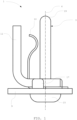
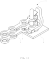
- Figure 1 shows a first exemplary carrier 1, which is suitable for receiving an implant in the form of a bone plate not shown here (see Figure 6 ).
- the carrier 1 contains an implant holder 3, an elastic element in the form of a spring 10 and a stopper 11, which are inserted into the Figures 2 to 4 are presented in detail.
- the implant holder 3 is essentially elongated along a longitudinal axis 4 and has a first part 5 and a second part 6.
- the first part 5 contains a shaft 7 for receiving one or more implants in respective recesses of the implant/implants.
- the implant holder 3 On the side of the first part 5, the implant holder 3 has a rounded end 19 for receiving the implant.
- the second part 6 contains a thread 14, for example an M3 thread, a first, conically formed fastening section 8 for fastening to a holding section of a container (not shown here) (see Figure 6 ) and a cross-sectional thickening in the form of a head 15. Between the thread 14 and the fastening section 8 there is a thread relief 29.
- the first fastening section 8 is arranged along the longitudinal axis 4 of the implant holder 3 between the thread 14 and the cross-sectional thickening 15.
- the stopper 11 is attached to the second part 6 of the implant holder 3, by means of the thread 14.
- the implant receptacle 3 extending along the longitudinal axis 4 in the direction of the first part 5 beyond the spring 10 and the second fastening section 12 of the spring 10 being clamped between the stopper 11 and the head 15 of the implant receptacle 3.
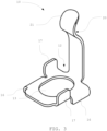
- the in Figure 3 The spring 10 shown extends along the longitudinal axis 4 of the implant holder 3 (see Figure 1 ).
- the spring 10 is elastic perpendicular to this direction and is arranged in such a way that it is elastically deformed when the implant is removed (see Figure 6 ). This provides a force component perpendicular to the longitudinal axis 4, whereby an implant held on the implant holder 3 can be secured.
- the spring 10 thus serves as a loss protection.
- the spring 10 has a second fastening section 12 with a recess 13 through which the implant holder 3 can be passed, whereby the spring 10 can be attached to the implant holder 3 (see Figure 1 ).
- the second fastening section 12 has two first wing-shaped extensions 16.
- the spring 10 can be aligned with the first extensions 16 on a holding section of a container (not shown here) (see Figure 8).
- the second fastening section 12 has two second extensions 17, with which the stopper 11 can be aligned with the spring 10 (see Figure 5 ).
- the first extensions 16 and the second extensions 17 extend in opposite directions with respect to the longitudinal axis 4 of the implant holder 3.
- the spring 10 is curved in the direction of the first part 5 of the implant holder 3 in such a way that the implant is secured against accidental loss (see Figures 1 and 6 ).
- the spring 10 is bent away in the direction of the first part 5 of the implant holder 3 in such a way that that an implant 2 elastically deforms the spring 10 during insertion.
- the in Figure 4 The stopper 11 shown individually has a stop 18 for the spring 10.
- the stop 18 is shaped and arranged in such a way that plastic deformation of the spring 10, in particular overbending, is prevented.
- the stopper 11 has an opening 28 through which the spring 10 can be passed.
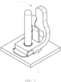
- the Figure 5 shows the carrier 1 attached to a holding section 9 of a container in a perspective view.
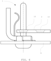
- FIG 6 An exemplary set with the first carrier 1 according to the invention and a bone plate 2 is shown. This set is attached to the holding section 9 of the container.
- the Figures 7a and 7b show a section of a holding section 9 of a container not shown in its entirety here, namely in Figure 7a without bone plate and in Figure 7b with a bone plate 2.
- the holding section 9 has an alignment recess 23 for the first extensions 16 of the spring 10.
- the alignment recess 23 is composed of a central, circular area 23a and two connected, opposite, essentially rectangular receiving areas 23b.
- the implant receptacle 3 is held in the circular area 23a and by means of the Figure 2
- the first extensions 16 of the spring 10 are held in the receiving areas 23b.
- the bone plate 2 is also held by a further implant holder 3', which is identical to the implant holder 3 and is attached to the holding section 9 in the same way as in Figure 6 shown.
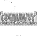
- FIG 8 A first exemplary container 50 with several such sets is shown. As can be seen from the figure Each carrier holds a bone plate together with a respective additional implant holder.
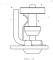
- FIG 9 shows an elastic locking element 22 for the carrier 1 according to the Figures 1 to 4 .
- the locking element 22 has a body 25 with a receiving opening 26 through which the shaft 7 of the implant holder 3 can be passed (see Figure 10 ).
- the body 25 also has a notch 27 into which the spring 10 engages. In this way, the locking element 22 can be secured to the implant holder 3 (see Figure 10 ).
- the locking element 22 prevents bone plates from being placed on the implant holder 3.
- FIG. 6 shows a set consisting of a carrier 1 and a bone plate 2 with two recesses 13.
- the implant receptacle 3 of the carrier 1 is received in a circular area 23a of the holding section 9 and guided through one of the recesses 13. This holds the bone plate 2.
- FIG. 8 shows a first container 50 according to the invention for bone plates 2.
- the container 50 has a base 24 with a holding section, wherein directly on the holding section (i.e. without any components arranged in between) a set according to Figure 6
- the shafts 7 extend perpendicular to the base 24.
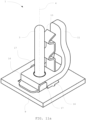
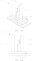
- the Figures 11a and 11b show a second exemplary carrier 1 in a perspective and a side view.
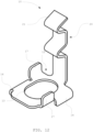
- This carrier 1 differs from the one shown in the Figures 1 to 4 shown essentially in the spring 10, which in Figure 12 is shown separately.
- the spring 10 In its end region 20, the spring 10 is curved not only at one but at two points in the direction of the implant holder 3. This allows two implants to be kept at a distance from each other, whereby the implants can also be better cleaned and especially sterilized.
- the second exemplary carrier 1 according to the Figures 11a and 11b is in Figure 13 together with two bone plates 2 held thereon.
- the carrier 1 is also attached to a holding section 9 of a container.
- This carrier 1 contains two implant holders 3 and a spring 10. As the Figure 14b As can be seen, the implant receptacle 3 shown there on the right also functions as a stopper 11 for the spring 10.
- This carrier 1 can accommodate a single bone plate that is held by one or both implant receptacles 3, or two bone plates that are each held on one of the two implant receptacles 3.
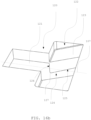
- FIG 15 shows a securing element 103 according to the invention of a further carrier according to the invention, which is however intended to accommodate one or more screws.
- the securing element 103 contains a central region 117 with several recesses 105 through which a screw can be removed (see Figure 17b ), as well as several elastically designed feet 111.
- the securing element 103 has a first spring element 108 formed in one piece.
- the securing element 103 has a second end region 118, also formed in one piece, which forms a second spring element and also has elastically designed feet 111.
- the securing element 103 is labeled by a laser marking 116.
- an actuating element 119 is formed which extends away from the feet 111, i.e. upwards.
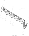
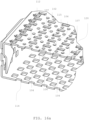
- Figure 16a shows a section of a container 114 according to the invention with a holder 102.
- the holder 102 has has several receptacles 104 for one screw each.
- the receptacles 104 are arranged along a straight line 107.
- the recesses 105 of the securing element 103 correspond to the receptacles 104 of the holder 102.
- the holder 102 also has elongated holder recesses 112 that are arranged along a line parallel to the line 107.
- the holder 102 has several contoured receiving openings 120.
- Figure 16b contains a detailed view of one of the contoured receiving openings 120.
- the receiving opening 120 has a rectangular passage area 121 with a longer side and a shorter side, the longer side extending parallel to the line 107.
- a wedge-shaped recess 122 with an inclined upper sliding surface 123 is provided on the top of the holder 102 and a wedge-shaped projection 124 with a lower sliding surface 125, a vertically extending locking surface 126 and a step 127 formed between them is provided on the underside of the holder 102.
- the Figures 17a and 17b show the container 114 with the holder 102 and a securing element 103.
- a screw 101 is inserted into each of the receptacles 104.
- the first spring element 108 is inserted into an opening in the holder 102 and the feet 111 of the second end region 118 in two adjacent contoured receiving openings 120.
- the feet 111 of the middle region 117 extend in the direction of the holder 102 and are locked into the holder recesses 112.
- the longitudinal extension of the feet 111 of the middle region 117 in the direction of the line 107 is less than the longitudinal extension of the holder recesses 112 in this direction. This has the effect that the securing element 103 is movably connected to the holder 102.
- the first spring element 108 is designed and arranged such that the securing element 103 is held in the first position P1.
- the Figures 17a and 17b also reveal a releasable locking device 110 which can lock into place and thus fix the securing element 103 in the second position P2 as soon as the securing element 103 reaches the second position P2.
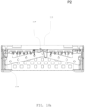
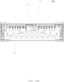
- FIGS 18a and 18b show in detail in side views how the movement of the securing element 103 takes place through the interaction with a lid 113 of the container 50.
- the feet 111 of the first end region 118 are pressed against the locking surfaces 126 by the first spring element 108.
- the cover 113 is not yet fully placed in this second position P2, so that there is still no contact with the actuating element 119.
- the securing element 103 After lifting the cover 113, the securing element 103 remains in the first position P1 due to the force caused by the first spring element 108.
- the feet 111 By exerting a force parallel to the line 107 on the actuating element 119, the feet 111 can be moved along the sliding surfaces 123, 125 up to over the step 127, whereby the second position P2 is reached and the feet 111 of the second end region 118 move upwards and thus back into the locking position due to the spring effect of the first end region 118.
- the transfer of the securing element 103 from the second position P2 to the first position P1 can of course also be carried out manually, i.e. without the action of the cover 113.
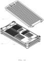
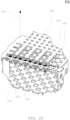
- Figure 19 shows a first container 114 according to the invention with a holder 102 and several supports 100, each of which has a securing element 103. Some of the securing elements 103 are in the first position P1 and the remaining ones in the second position P2.
- Figure 20 the container 114 is shown together with a lid 113 with which it can be closed.
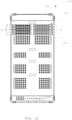
- the Figures 21 to 24 show a further embodiment.
- the securing elements 103 of the Figure 23 The carriers 100 shown on the left are in the second position P2, in which the securing elements 103 protrude beyond the edge of the container 114.
- the securing elements 103 of the Figure 23 The carriers 100 shown on the right are in the first position P1 and do not protrude beyond the edge of the container 114.
- no lid 113 can be placed on the container 114. This is only possible if the securing elements 103 are transferred to the first position P1, in which they do not protrude beyond the edge of the container 114.
- the screws 101 are thus always secured against falling out when the lid 113 is in place.
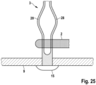
- the exemplary carrier 1 for a bone plate 2 shown contains two leaf springs 28 which extend essentially along the common longitudinal axis 4, but which are spaced apart from one another in a central region. If a bone plate 2 with a recess is placed over the leaf springs 28, the leaf springs 28 are pressed against one another and the bone plate 2 can be pushed over the central region. After the bone plate 2 has passed the central region, the leaf springs 28 spring apart again and thus secure the bone plate 2 against accidentally falling out.
- Figure 26 shows a spring 10 of another exemplary carrier 1.
- the spring 10 has a tab 41 with an end 42 that is guided in a rail 43.
- One end 44 of the rail 43 forms a stop that prevents excessive bending of the spring 10.
- FIG. 27a and 27b another carrier 1 for a bone plate is shown.
- the carrier 1 contains a shaft 31 for receiving the bone plate at one of its recesses.
- the shaft 31 has means for fastening to a holding section 9 of a container at a first, here lower end 32.
- the carrier 1 also contains a locking element 34 which is pivotably arranged at a second, here upper end 33 of the shaft 31 opposite the first end 32 of the shaft 31.
- the locking element 34 can be inserted into a Figure 27a shown recording position and in a Figure 27b shown locking position. In the receiving position, the bone plate with the recess can be moved onto the shaft 31 via the locking element 34. By pivoting the locking element 34 into the locking position, the locking element 34 prevents the bone plate from being removed.
Landscapes
- Health & Medical Sciences (AREA)
- Surgery (AREA)
- Life Sciences & Earth Sciences (AREA)
- Molecular Biology (AREA)
- General Health & Medical Sciences (AREA)
- Veterinary Medicine (AREA)
- Engineering & Computer Science (AREA)
- Biomedical Technology (AREA)
- Heart & Thoracic Surgery (AREA)
- Medical Informatics (AREA)
- Nuclear Medicine, Radiotherapy & Molecular Imaging (AREA)
- Animal Behavior & Ethology (AREA)
- Public Health (AREA)
- Orthopedic Medicine & Surgery (AREA)
- Pathology (AREA)
- Oral & Maxillofacial Surgery (AREA)
- Neurology (AREA)
- Dental Prosthetics (AREA)
- Prostheses (AREA)
- Surgical Instruments (AREA)
- Packages (AREA)
Claims (15)
- Support (100) destiné à recevoir au moins un objet chirurgical, en particulier un implant, notamment une vis (101), contenant :- un posage (102) comprenant au moins un logement (104) pour ledit au moins un objet chirurgical,- un élément de sécurisation (103) pour ledit au moins un objet,
dans lequel- l'élément de sécurisation (103) présente au moins un évidement (105) pour l'enlèvement du au moins un objet à travers l'évidement (105),- l'élément de sécurisation (103) est relié de manière mobile au posage (102), de sorte que élément de sécurisation (103) peut être déplacé d'une première position (P1) à une seconde position (P2),- dans la première position (P1) de l'élément de sécurisation (103) par rapport au posage (102), l'au moins un objet est bloqué, et- dans la deuxième position (P2) de l'élément de sécurisation par rapport au posage (102), le au moins un objet peut être retiré du logement (104) à travers l'évidement (105) de l'élément de sécurisation (103) le long d'une direction de retrait (106). - Support (100) selon la revendication 1, dans lequel le support (100) est inséré dans un conteneur (114) qui peut être fermé par un couvercle (113), et dans lequel l'élément de sécurisation (103) est ou peut être amené en liaison active avec le couvercle (113) lors de la fermeture du couvercle (113) de telle sorte que l'élément de sécurisation (103) est amené dans la première position (P1) par la fermeture du couvercle (113).
- Support (100) selon l'une des revendications 1 et 2, dans lequel le posage (102) présente deux ou trois ou plusieurs logements (104) pour des objets chirurgicaux (101) et dans lequel l'élément de sécurisation (103) présente des évidements (105) correspondant aux logements (104), les objets chirurgicaux (101) pouvant être fixés dans la première position (P1) dans les logements (104) par l'élément de sécurisation (103) et pouvant être retirés dans la deuxième position (P1) par les évidements (105) correspondant respectivement dans l'élément de sécurisation (103).
- Support (100) selon la revendication 3, dans lequel les logements (104) sont disposés le long d'une ligne droite (107) .
- Support (100) selon l'une des revendications 1 à 4, dans lequel le support (100), notamment l'élément de sécurisation (103), comporte un premier élément de ressort (108) configuré et agencé de manière à maintenir l'élément de sécurisation (103) dans la première position (P1).
- Support (100) selon la revendication 5, dans lequel le premier élément de ressort (108) est disposé dans une première zone d'extrémité (109) de l'élément de sécurisation (103) et est de préférence formé d'une seule pièce avec l'élément de sécurisation (103).
- Support (100) selon l'une des revendications 1 à 6, dans lequel le support (100) comporte un dispositif d'encliquetage (110) configuré pour s'encliqueter et fixer l'élément de sécurisation (103) dans la deuxième position (P2) dès que l'élément de sécurisation (103) atteint la deuxième position (P2).
- Support (100) selon la revendication 7, dans lequel le dispositif d'encliquetage (110) est libérable.
- Support (100) selon l'une des revendications 1 à 8, dans lequel la direction de retrait (106) correspond sensiblement à un axe longitudinal d'un objet (101) maintenu dans l'évidement (105) conformément à sa destination.
- Support (100) selon l'une des revendications 1 à 9, dans lequel l'élément de sécurisation (103) est marqué, de préférence par un marquage laser (116).
- Support (100) selon l'une quelconque des revendications 1 à 10, dans lequel l'élément de sécurisation (103) comprend au moins deux pieds (111) qui s'étendent depuis l'élément de sécurisation (103) en direction du posage (102), dans lequel les pieds (111) sont élastiques et dans lequel les pieds (111) forment au moins partiellement un contour opposé à une partie du posage (102), de sorte que les pieds (111) peuvent être encliquetés sur le posage (102).
- Support (100) selon la revendication 11, dans lequel les pieds (111), à l'état engagé, peuvent être déplacés le long d'un bord (115) du posage (102) de la première position (P1) à la deuxième position (P2).
- Support (100) selon la revendication 12, dans lequel les bords (115) pour les pieds (111) sont formés par des évidements de maintien allongés (112) dans le posage (102).
- Ensemble constitué d'un support (100) selon l'une des revendications 1 à 13 et d'au moins un objet chirurgical, en particulier un implant chirurgical, notamment une vis (101), l'objet chirurgical (101) présentant un épaississement de section, de préférence une tête, qui repose de préférence sur un bord du logement (104), l'élément de sécurisation (103) étant disposé dans la première position (P1) de telle sorte que l'épaississement de section soit bloqué et ne puisse pas être retiré le long de la direction de retrait (106).
- Conteneur (114) pour objets chirurgicaux, en particulier des implants chirurgicaux, notamment des vis (101), contenant au moins un, de préférence plusieurs, support(s) (100) selon l'une des revendications 1 à 13 et/ou des ensembles selon la revendication 14.
Applications Claiming Priority (1)
| Application Number | Priority Date | Filing Date | Title |
|---|---|---|---|
| PCT/EP2020/053824 WO2021160274A1 (fr) | 2020-02-14 | 2020-02-14 | Supports pour articles chirurgicaux, ensembles et récipients comprenant de tels supports |
Publications (3)
| Publication Number | Publication Date |
|---|---|
| EP4103085A1 EP4103085A1 (fr) | 2022-12-21 |
| EP4103085B1 true EP4103085B1 (fr) | 2024-11-06 |
| EP4103085C0 EP4103085C0 (fr) | 2024-11-06 |
Family
ID=69740323
Family Applications (1)
| Application Number | Title | Priority Date | Filing Date |
|---|---|---|---|
| EP20708436.9A Active EP4103085B1 (fr) | 2020-02-14 | 2020-02-14 | Supports pour articles chirurgicaux, ensembles et récipients comprenant de tels supports |
Country Status (7)
| Country | Link |
|---|---|
| US (1) | US20230218361A1 (fr) |
| EP (1) | EP4103085B1 (fr) |
| JP (1) | JP2023515388A (fr) |
| AU (1) | AU2020429135A1 (fr) |
| BR (1) | BR112022014980A2 (fr) |
| MX (1) | MX2022010005A (fr) |
| WO (1) | WO2021160274A1 (fr) |
Families Citing this family (3)
| Publication number | Priority date | Publication date | Assignee | Title |
|---|---|---|---|---|
| US11819399B2 (en) * | 2021-07-06 | 2023-11-21 | Wright Medical Technology, Inc. | Systems and methods of plate trial packaging |
| DE102023103493A1 (de) * | 2023-02-14 | 2024-08-14 | Aesculap Ag | Instrumentensieb für ärztliche, insbesondere chirurgische Instrumente |
| US12036050B1 (en) * | 2023-04-27 | 2024-07-16 | Sure Count Surgical, Llc | Management systems for surgical instruments and items used during surgery |
Family Cites Families (9)
| Publication number | Priority date | Publication date | Assignee | Title |
|---|---|---|---|---|
| NZ550345A (en) * | 2004-03-07 | 2009-11-27 | Synthes Gmbh | Container and carrier system for holding and presenting surgical materials such as bone screws |
| DE102004046984B4 (de) * | 2004-09-28 | 2010-09-02 | Stryker Leibinger Gmbh & Co. Kg | Vorrichtung und System zum Bereithalten von lang gestreckten chirurgischen Befestigungselementen |
| DE102006062688A1 (de) * | 2006-04-07 | 2007-10-11 | Medicon Eg, Chirurgiemechaniker-Genossenschaft | Lagerungssystem für chirurgische Instrumente, Implantate und Schraubenverpackungen |
| DE102007011093B3 (de) * | 2007-02-28 | 2008-06-19 | Aesculap Ag & Co. Kg | Chirurgischer Datenträger |
| EP2187832B1 (fr) | 2007-08-22 | 2021-06-30 | Medartis Holding AG | Support pour matériel chirurgical et plaques d'osthéosynthèse |
| US20090266728A1 (en) * | 2008-04-25 | 2009-10-29 | Warsaw Orthopedic, Inc. | Medical device tracking system with tray and method |
| DE202009002639U1 (de) | 2009-02-26 | 2009-05-07 | Medartis Ag | Träger und Halterung für chirurgische Gegenstände |
| EP2392286B1 (fr) | 2010-06-03 | 2015-05-20 | Medartis AG | Unité de stockage de vis à os, ensemble et récipient chirurgical |
| EP3181060B1 (fr) * | 2015-12-14 | 2018-12-05 | Stryker European Holdings I, LLC | Ensemble d'emballage stérile universel |
-
2020
- 2020-02-14 JP JP2022548996A patent/JP2023515388A/ja active Pending
- 2020-02-14 AU AU2020429135A patent/AU2020429135A1/en not_active Abandoned
- 2020-02-14 WO PCT/EP2020/053824 patent/WO2021160274A1/fr not_active Ceased
- 2020-02-14 EP EP20708436.9A patent/EP4103085B1/fr active Active
- 2020-02-14 MX MX2022010005A patent/MX2022010005A/es unknown
- 2020-02-14 US US17/799,456 patent/US20230218361A1/en not_active Abandoned
- 2020-02-14 BR BR112022014980A patent/BR112022014980A2/pt not_active IP Right Cessation
Also Published As
| Publication number | Publication date |
|---|---|
| MX2022010005A (es) | 2022-09-19 |
| BR112022014980A2 (pt) | 2022-09-20 |
| AU2020429135A1 (en) | 2022-08-25 |
| US20230218361A1 (en) | 2023-07-13 |
| WO2021160274A1 (fr) | 2021-08-19 |
| EP4103085C0 (fr) | 2024-11-06 |
| EP4103085A1 (fr) | 2022-12-21 |
| JP2023515388A (ja) | 2023-04-13 |
Similar Documents
| Publication | Publication Date | Title |
|---|---|---|
| EP2377485B1 (fr) | Fixation chirurgicale pour un récipient chirurgical et récipient chirurgical | |
| EP2187832B1 (fr) | Support pour matériel chirurgical et plaques d'osthéosynthèse | |
| EP1752668B1 (fr) | Dispositif pour empêcher le mouvement axial d'un boulon avec une cannelure | |
| DE2633972C3 (de) | Anordnung zum Verbinden zweier Bauteile | |
| DE102006046428A1 (de) | Sternumverschluss | |
| EP1985264A1 (fr) | Orthèse | |
| EP2559628A1 (fr) | Récipient empilable ainsi qu'agencement de récipients avec plusieurs récipients de ce type | |
| EP0528341B1 (fr) | Dispositif pour la fixation détachable d'un boîtier d'appareil à un rail profilé | |
| EP2392286B1 (fr) | Unité de stockage de vis à os, ensemble et récipient chirurgical | |
| WO2021160274A1 (fr) | Supports pour articles chirurgicaux, ensembles et récipients comprenant de tels supports | |
| EP0528371B1 (fr) | Boîtier pour fixation murale ou au sol | |
| EP4444214B1 (fr) | Tamis pour instruments médicaux, en particulier instruments chirurgicaux | |
| DE3530632A1 (de) | Abheftvorrichtung fuer blattlagen | |
| DE10317871B3 (de) | Osteosynthese-Vorrichtung | |
| DE2227625A1 (de) | Heftvorrichtung fuer schnellhefter | |
| EP3858185B1 (fr) | Serrure et contenant doté d'une serrure | |
| DE69317375T2 (de) | Hülle für Pflanzen oder Blumen in einem topfartigen Behälter | |
| DE102005047187B4 (de) | Chirurgisches Befestigungselement für ein chirurgisches Profilelement eines chirurgischen Behälters, Profilelement, Satz solcher Befestigungs- oder Profilelemente, Behälter | |
| EP3566775B1 (fr) | Pile de cassettes composée de cassettes individuelles, de préférence destinée à la réception des préparations pour analyses de laboratoire | |
| WO2000053376A1 (fr) | Support de clefs males coudees | |
| AT411894B (de) | Klammer zum klemmen von blättern | |
| EP0389438B1 (fr) | Pare-neige | |
| DE3146393C2 (de) | Briefordnermechanik | |
| DE3146392A1 (de) | Briefordnermechanik | |
| DE202004004066U1 (de) | Verschluß mit Klemmbefestigung |
Legal Events
| Date | Code | Title | Description |
|---|---|---|---|
| STAA | Information on the status of an ep patent application or granted ep patent |
Free format text: STATUS: UNKNOWN |
|
| STAA | Information on the status of an ep patent application or granted ep patent |
Free format text: STATUS: THE INTERNATIONAL PUBLICATION HAS BEEN MADE |
|
| PUAI | Public reference made under article 153(3) epc to a published international application that has entered the european phase |
Free format text: ORIGINAL CODE: 0009012 |
|
| STAA | Information on the status of an ep patent application or granted ep patent |
Free format text: STATUS: REQUEST FOR EXAMINATION WAS MADE |
|
| 17P | Request for examination filed |
Effective date: 20220726 |
|
| AK | Designated contracting states |
Kind code of ref document: A1 Designated state(s): AL AT BE BG CH CY CZ DE DK EE ES FI FR GB GR HR HU IE IS IT LI LT LU LV MC MK MT NL NO PL PT RO RS SE SI SK SM TR |
|
| DAV | Request for validation of the european patent (deleted) | ||
| DAX | Request for extension of the european patent (deleted) | ||
| GRAP | Despatch of communication of intention to grant a patent |
Free format text: ORIGINAL CODE: EPIDOSNIGR1 |
|
| STAA | Information on the status of an ep patent application or granted ep patent |
Free format text: STATUS: GRANT OF PATENT IS INTENDED |
|
| RIC1 | Information provided on ipc code assigned before grant |
Ipc: A61B 50/30 20160101ALI20240508BHEP Ipc: A61B 50/22 20160101ALI20240508BHEP Ipc: A61B 50/20 20160101ALI20240508BHEP Ipc: A61B 90/94 20160101ALI20240508BHEP Ipc: A61B 50/00 20160101ALI20240508BHEP Ipc: A61B 17/86 20060101AFI20240508BHEP |
|
| INTG | Intention to grant announced |
Effective date: 20240603 |
|
| GRAS | Grant fee paid |
Free format text: ORIGINAL CODE: EPIDOSNIGR3 |
|
| GRAA | (expected) grant |
Free format text: ORIGINAL CODE: 0009210 |
|
| STAA | Information on the status of an ep patent application or granted ep patent |
Free format text: STATUS: THE PATENT HAS BEEN GRANTED |
|
| AK | Designated contracting states |
Kind code of ref document: B1 Designated state(s): AL AT BE BG CH CY CZ DE DK EE ES FI FR GB GR HR HU IE IS IT LI LT LU LV MC MK MT NL NO PL PT RO RS SE SI SK SM TR |
|
| REG | Reference to a national code |
Ref country code: GB Ref legal event code: FG4D Free format text: NOT ENGLISH |
|
| REG | Reference to a national code |
Ref country code: CH Ref legal event code: EP |
|
| REG | Reference to a national code |
Ref country code: DE Ref legal event code: R096 Ref document number: 502020009685 Country of ref document: DE |
|
| REG | Reference to a national code |
Ref country code: IE Ref legal event code: FG4D Free format text: LANGUAGE OF EP DOCUMENT: GERMAN |
|
| U01 | Request for unitary effect filed |
Effective date: 20241129 |
|
| U07 | Unitary effect registered |
Designated state(s): AT BE BG DE DK EE FI FR IT LT LU LV MT NL PT RO SE SI Effective date: 20241210 |
|
| U20 | Renewal fee for the european patent with unitary effect paid |
Year of fee payment: 6 Effective date: 20250130 |
|
| PG25 | Lapsed in a contracting state [announced via postgrant information from national office to epo] |
Ref country code: IS Free format text: LAPSE BECAUSE OF FAILURE TO SUBMIT A TRANSLATION OF THE DESCRIPTION OR TO PAY THE FEE WITHIN THE PRESCRIBED TIME-LIMIT Effective date: 20250306 Ref country code: HR Free format text: LAPSE BECAUSE OF FAILURE TO SUBMIT A TRANSLATION OF THE DESCRIPTION OR TO PAY THE FEE WITHIN THE PRESCRIBED TIME-LIMIT Effective date: 20241106 |
|
| PG25 | Lapsed in a contracting state [announced via postgrant information from national office to epo] |
Ref country code: ES Free format text: LAPSE BECAUSE OF FAILURE TO SUBMIT A TRANSLATION OF THE DESCRIPTION OR TO PAY THE FEE WITHIN THE PRESCRIBED TIME-LIMIT Effective date: 20241106 |
|
| PG25 | Lapsed in a contracting state [announced via postgrant information from national office to epo] |
Ref country code: NO Free format text: LAPSE BECAUSE OF FAILURE TO SUBMIT A TRANSLATION OF THE DESCRIPTION OR TO PAY THE FEE WITHIN THE PRESCRIBED TIME-LIMIT Effective date: 20250206 |
|
| PG25 | Lapsed in a contracting state [announced via postgrant information from national office to epo] |
Ref country code: GR Free format text: LAPSE BECAUSE OF FAILURE TO SUBMIT A TRANSLATION OF THE DESCRIPTION OR TO PAY THE FEE WITHIN THE PRESCRIBED TIME-LIMIT Effective date: 20250207 |
|
| PGFP | Annual fee paid to national office [announced via postgrant information from national office to epo] |
Ref country code: CH Payment date: 20250301 Year of fee payment: 6 |
|
| PG25 | Lapsed in a contracting state [announced via postgrant information from national office to epo] |
Ref country code: PL Free format text: LAPSE BECAUSE OF FAILURE TO SUBMIT A TRANSLATION OF THE DESCRIPTION OR TO PAY THE FEE WITHIN THE PRESCRIBED TIME-LIMIT Effective date: 20241106 |
|
| PGFP | Annual fee paid to national office [announced via postgrant information from national office to epo] |
Ref country code: GB Payment date: 20250206 Year of fee payment: 6 |
|
| PG25 | Lapsed in a contracting state [announced via postgrant information from national office to epo] |
Ref country code: RS Free format text: LAPSE BECAUSE OF FAILURE TO SUBMIT A TRANSLATION OF THE DESCRIPTION OR TO PAY THE FEE WITHIN THE PRESCRIBED TIME-LIMIT Effective date: 20250206 |
|
| PG25 | Lapsed in a contracting state [announced via postgrant information from national office to epo] |
Ref country code: SM Free format text: LAPSE BECAUSE OF FAILURE TO SUBMIT A TRANSLATION OF THE DESCRIPTION OR TO PAY THE FEE WITHIN THE PRESCRIBED TIME-LIMIT Effective date: 20241106 |
|
| PG25 | Lapsed in a contracting state [announced via postgrant information from national office to epo] |
Ref country code: SK Free format text: LAPSE BECAUSE OF FAILURE TO SUBMIT A TRANSLATION OF THE DESCRIPTION OR TO PAY THE FEE WITHIN THE PRESCRIBED TIME-LIMIT Effective date: 20241106 |
|
| PG25 | Lapsed in a contracting state [announced via postgrant information from national office to epo] |
Ref country code: CZ Free format text: LAPSE BECAUSE OF FAILURE TO SUBMIT A TRANSLATION OF THE DESCRIPTION OR TO PAY THE FEE WITHIN THE PRESCRIBED TIME-LIMIT Effective date: 20241106 |
|
| PLBE | No opposition filed within time limit |
Free format text: ORIGINAL CODE: 0009261 |
|
| STAA | Information on the status of an ep patent application or granted ep patent |
Free format text: STATUS: NO OPPOSITION FILED WITHIN TIME LIMIT |
|
| PG25 | Lapsed in a contracting state [announced via postgrant information from national office to epo] |
Ref country code: MC Free format text: LAPSE BECAUSE OF FAILURE TO SUBMIT A TRANSLATION OF THE DESCRIPTION OR TO PAY THE FEE WITHIN THE PRESCRIBED TIME-LIMIT Effective date: 20241106 |
|
| 26N | No opposition filed |
Effective date: 20250807 |
|
| PG25 | Lapsed in a contracting state [announced via postgrant information from national office to epo] |
Ref country code: IE Free format text: LAPSE BECAUSE OF NON-PAYMENT OF DUE FEES Effective date: 20250214 |
|
| REG | Reference to a national code |
Ref country code: CH Ref legal event code: Y10 Free format text: ST27 STATUS EVENT CODE: U-0-0-Y10-Y00 (AS PROVIDED BY THE NATIONAL OFFICE) Effective date: 20260305 |