EP4103357B1 - Pince - Google Patents
Pince Download PDFInfo
- Publication number
- EP4103357B1 EP4103357B1 EP21704745.5A EP21704745A EP4103357B1 EP 4103357 B1 EP4103357 B1 EP 4103357B1 EP 21704745 A EP21704745 A EP 21704745A EP 4103357 B1 EP4103357 B1 EP 4103357B1
- Authority
- EP
- European Patent Office
- Prior art keywords
- pliers
- movable
- pivot bolt
- plier arm
- hinge pin
- Prior art date
- Legal status (The legal status is an assumption and is not a legal conclusion. Google has not performed a legal analysis and makes no representation as to the accuracy of the status listed.)
- Active
Links
Images





Classifications
-
- B—PERFORMING OPERATIONS; TRANSPORTING
- B25—HAND TOOLS; PORTABLE POWER-DRIVEN TOOLS; MANIPULATORS
- B25B—TOOLS OR BENCH DEVICES NOT OTHERWISE PROVIDED FOR, FOR FASTENING, CONNECTING, DISENGAGING, OR HOLDING
- B25B7/00—Pliers; Other hand-held gripping tools with jaws on pivoted limbs; Details applicable generally to pivoted-limb hand tools
- B25B7/06—Joints
- B25B7/10—Joints with adjustable fulcrum
Definitions
- the invention relates to a pair of pliers and is described in claims 1 to 15.
- Pliers of the type in question are known in various designs, for example in the form of pipe or water pump pliers, and also in the form of so-called pliers wrenches or screw pliers.
- the cancellation of the toothing engagement can be achieved as a result of a pivoting displacement of the hinge pin about its longitudinal axis.
- Pliers designed in this way are known, for example, from EP 3 313 619 A1 or from the EP 2 596 912 A1
- a securing of the hinge pin in the direction opposite to the mounting direction of the hinge pin can be provided according to the known state of the art by a collar that can be arranged on the hinge pin after assembly and forms the locking projection, which collar is connected to a facing outer surface of the movable pliers leg.
- the area of the pliers leg surrounding the receptacle forms the locking part, which prevents the hinge pin from moving in the direction of its longitudinal axis.
- the collar forming the locking projection can be attached separately to the hinge pin, for example by screwing or riveting.
- the collar protrudes at least partially over the outer contour of the hinge pin in the area of its counter-toothing when viewed over its circumference.
- a pair of pliers with a jaw that can be moved along the fixed jaw is known, for example, from the DE 39 29 323 C2 Such pliers can be referred to as so-called pliers wrenches.
- the hinge pin can be slid along the axis of rotation to remove the teeth.
- This hinge pin has a driving projection of such a length that it is also caught in the driving recess in the actuated position.
- the hinge pin can be moved by pivoting the pliers lever from the engaged position against the force of a spring, but is held in the mounted position by riveting or locking with an opposite is.
- the hinge pin is only pivotally mounted in both pliers arms. A locking part is provided on one of the pliers arms, which sits in a receptacle with a base.
- the invention has the object of improving a pair of pliers of the type in question while still maintaining a high level of user-friendliness, in particular with regard to an easy-to-use assembly of the hinge pin.
- the invention has the object of designing such a pair of pliers in a way that is easy to handle.
- This task is solved according to a first inventive idea in a pair of pliers, in which the locking projection and the locking part are designed to overrun each other during assembly, whereby the effect of the spring is overcome.
- This design enables a favorable assembly of the hinge pin. For assembly, this can be brought into an orientation relative to the receptacle in which an overrun of the locking projection and locking part is possible.
- the locking projection on the pin side can thus, for example, overrun the locking part on the pliers leg starting from a position on the outside of the leg to a position on the inside of the leg during a plugging process in which the hinge pin is inserted essentially along its longitudinal axis.
- the effect of the spring is canceled, for example by deliberately holding the spring in a tensioned position so that it cannot develop its force.
- the hinge pin can then be directly or also by user intervention, in which the hinge pin, for example, around whose longitudinal axis is pivotally displaced, into the holding position acting in the direction of the longitudinal axis.
- This pivoting return displacement can advantageously be brought about by releasing the spring effect.
- the locking projection can, as is also preferred, advantageously be a direct part of the hinge pin, and furthermore, as is further preferred, can be formed in one piece and, if necessary, of the same material as the hinge pin and its counter-toothing.
- a further solution to the problem can be achieved according to a further inventive idea in that the receptacle is formed with a base on the movable pliers leg.
- the mount is preferably designed to be closed on one side in the axial direction.
- the axial depth of the mount is limited so that the base can also prevent the hinge pin from moving axially in one axial direction.
- the proposed base design of the holder means that the corresponding leg section of the movable pliers leg is designed to be closed, which can facilitate the cleaning and maintenance of the pliers and, if necessary, also the assembly of the hinge pin.
- the task can also be solved by the locking projection and the engagement projection being essentially radial to the axis of rotation and that the locking projection has a locking flank aligned substantially radially to the axis of rotation.
- the interaction of the additionally provided locking projection with the movable jaw can result in a safeguard against an undesirable displacement of the movable jaw relative to the fixed pliers leg.
- the predetermined pivoting position of the movable pliers legs relative to one another in which the above-described safeguard is achieved due to the interaction of the locking projection with the movable jaw, can be provided, for example, in a position in which the toothing of the hinge pin with the longitudinal slot is released and/or in a position in which the engagement of the engagement projection in the intended recess of the movable jaw is released.
- an engagement transfer can be achieved from the engagement projection interacting with the recess of the movable jaw to the locking projection then interacting with the movable jaw, so that even after a possible cancellation of the interaction of the engagement projection and the recess of the jaw, the displaceability of the movable jaw on the fixed pliers leg can be achieved solely together with a displacement of the movable pliers leg along the longitudinal slot.
- the movable jaw thus always remains captive on the fixed pliers leg, regardless of the pivoting position of the movable pliers leg relative to the fixed pliers leg.
- the base of the receptacle is made of the same material and preferably in one piece with the pliers leg, in particular with the movable pliers leg.
- the spring can prevent the assembly position from being reached when the pliers are mounted, so that dismantling the hinge pin is not possible during normal operation or during normal handling of the pliers. It is even preferred that such a position, which would enable dismantling of the hinge pin, is not reached during normal use of the pliers.
- the receptacle is formed in the movable pliers leg.
- the movable pliers leg can enclose the fixed pliers leg in the area of the longitudinal slot in a fork-like manner. With such a fork-shaped design of the movable pliers leg, the receptacle can only be formed in the area of one fork leg.
- the locking projection can, in particular in the assembly position of the hinge pin, interact with an inner surface of the receptacle facing the fixed pliers leg, furthermore in particular with regard to holding the hinge pin in the direction of the longitudinal axis.
- the locking part on the receptacle side accordingly offers a locking surface for the locking projection, so that the hinge pin is caught in the direction of the longitudinal axis after assembly, in particular against the assembly direction.
- the cooperating surface of the locking part is preferably located in a hidden position, at least in an area that is not or not usually accessible during normal use of the pliers.
- the receptacle can, as is also preferred, have an insertion opening with an extension area.
- This insertion opening is preferably part of the receptacle.
- the hinge pin is inserted through the insertion opening essentially in the direction of the longitudinal axis.
- the locking projection provided on the pin side can, as is further preferred, be guided through the extension area of the insertion opening to finally run over the locking part on the receptacle side.
- the locking projection can be adapted with regard to its cross-sectional area viewed transversely to the longitudinal axis to the opening area of the extension area viewed in the same cutting plane. This can also result in a type of keyhole formation, with the keyhole being formed by the insertion opening with the extension area and the key shaft with the key bit being formed by the hinge pin with the locking projection.
- the hinge pin is to be arranged in a selected rotational position relative to its longitudinal axis and the extent of the longitudinal slot in order to pass through the insertion opening.
- This rotational position of the hinge pin preferably does not correspond to a normal operating position of the hinge pin when using the pliers. Rather, the selected rotational position is preferably intended solely and exclusively for the assembly of the hinge pin, but if necessary also for a targeted disassembly of the hinge pin.
- the hinge pin can have an elastic return element for pre-tensioning the hinge pin into the toothed engagement.
- the elastic return element can be a spring element arranged on the hinge pin, which acts directly or indirectly against a support surface, preferably of the fixed leg.
- the support surface can be provided in the region of the longitudinal slot, more preferably essentially opposite the slot-side toothing.
- the elastic return element can have a compression spring, for example a cylinder compression spring, which acts on a separate support element, for example in the form of a ball.
- the tooth engagement must be canceled by moving the hinge pin around its longitudinal axis. This pivoting movement of the hinge pin takes place against the restoring force of the elastic restoring element.
- the elastic return element can be moved into a specific compression position in the rotational position of the joint pin selected for this purpose as the joint pin with its locking projection passes through the insertion opening with the intended expansion area. This can, for example, be a maximum possible compression position of the return element.
- This particular compression position may, as is preferred, not be achievable during normal use of the pliers.
- the selected rotational position of the hinge pin suitable for passing through the insertion opening cannot be reached. A lifting of the The locking mechanism of the hinge pin on the pliers legs is thus counteracted.
- the hinge pin can be accommodated in a section of the receptacle that is only partially circular and has a driving shoulder that deviates from a circular course, for interaction with a driving flank of the hinge pin, wherein the hinge pin is rotatably guided in a circular recess of the receptacle and a circular line is defined by the circular recess, wherein the driving shoulder protrudes radially inwards with respect to the circular line and the driving flank is also formed within the circular line.
- the driving shoulder of the hinge pin can extend within a preferably circular contour of the same - viewed in a plane perpendicular to the pin axis.
- the rotational displacement of the hinge pin to remove the toothing can preferably only be carried out intentionally. To do this, the jaws of the pliers are opened beyond the usual extent using the movable pliers leg. The toothing engagement is removed solely by appropriate pivoting or rotational displacement of the pliers legs relative to each other. No further manual intervention by the user in the area of the hinge pin is necessary.
- the hinge pin can only be moved about its longitudinal axis, but not along the longitudinal axis.
- the jaw of the pliers is designed to be movable relative to the fixed pliers leg.
- the pliers can be designed in the manner of a pliers wrench.
- the locking projection like the engagement projection, is aligned substantially radially to the axis of rotation and the locking projection has a locking flank aligned substantially radially to the axis of rotation.
- the engagement flank of the movable jaw is arranged such that, in cooperation with the locking projection, it prevents the movable jaw from being displaced relative to the movable pliers leg in and/or against the direction of the fixed jaw.
- the engagement flank can be part of a locking recess in which the locking projection lies in the predetermined pivoting position of the movable pliers leg.
- a positive engagement of the locking projection in the locking recess can result, so that, if necessary, both an obstruction of the displacement of the movable jaw relative to the movable pliers leg in the direction of the fixed jaw as well as in the opposite direction.
- the predetermined pivoting position of the movable pliers leg relative to the fixed pliers leg can also correspond to the opening position of the pliers.
- This opening position of the pliers defining the predetermined pivoting position can also be a position of the movable pliers leg relative to the fixed pliers leg in which the toothing engagement between hinge pin and longitudinal slot is reached so that a sliding displacement of the movable pliers leg together with the movable jaw along the longitudinal slot can be carried out to change the opening width of the jaws.
- a pair of pliers 1 of a first embodiment in the form of water pump pliers Shown and described is, first of all, with reference to the Figures 1 and 2 , a pair of pliers 1 of a first embodiment in the form of water pump pliers.
- the pliers 1 have two pliers legs 2 and 3 which cross in a hinge pin 4, the pliers leg 2 being described below as a fixed pliers leg and the pliers leg 3 as a movable pliers leg.
- the pliers legs 2 and 3 of the pliers 1 of the first embodiment form handle sections 5 and 6 on one side of the hinge pin 4 and jaws 7 and 8 on the other side of the hinge pin 4, preferably in one piece and made of the same material as the handle sections 5 and 6, which delimit a pliers mouth M.
- leg section 12 of the fixed pliers leg 2 can be designed in the manner of a bearing plate, with two guide grooves 40 machined on the outer surfaces, which preferably run symmetrically to a pliers center axis.
- the sliding displacement of the movable jaw 8 on the fixed pliers leg 2 is achieved as a result of a pivoting displacement of the movable jaw 3.
- the movable jaw 3, which fork-like surrounds the bearing plate of the fixed pliers leg 2 has an engagement projection 43 on each fork section that projects essentially radially to the longitudinal axis x and engages in a preferably contour-adapted recess 44 of the jaw 8 in the area of the guide section 42.
- a pivoting movement of the movable jaw 3 is thus converted into a linear displacement of the movable jaw 8 along the guide groove 40 via the interaction of the engagement projection 43 and recess 44.
- the movable jaw 8 can thus be moved in the direction of a pliers jaw closed position or in the direction of a pliers jaw open position via this pivoting displacement of the movable jaw 3.
- the pliers leg 3 is rotatable about the geometric longitudinal axis x of the hinge pin 4 relative to the pliers leg 2 in order to change the width of the pliers jaw M which is positioned between the jaws 7 and 8.
- the fixed pliers leg 2 has a longitudinal slot 9 in the intersection area of the pliers legs 2 and 3.
- the longitudinal slot 9 extends essentially parallel to the guide grooves 40.
- This longitudinal slot In the usual position of use of the pliers 1, the articulated bolt 4 passes through the 9, the geometric longitudinal axis x of which preferably runs perpendicular to a plane spanned by the circumferential edge contour of the longitudinal slot 9.
- the movable pliers leg 3 can, as is also preferred, be fork-shaped in the intersection area of the pliers legs 2 and 3, having fork sections 10 and 11 running parallel and spaced apart from one another, which flank the leg section 12 of the fixed pliers leg 2 having the longitudinal slot 9.
- the fixed pliers leg 11 is inserted through the fork area 13 of the movable pliers leg 3.
- the hinge pin 4 is rotatably mounted in the fork sections 10 and 11 of the movable pliers leg 3.
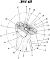
- one fork section 10 can have a pivoting position with a plan view according to Figures 2 or 16 circular insertion opening 27 and the fork section 11 on the inside of the wall, ie facing the leg section 12, with a pin-like centering projection 16.
- the insertion opening 27 and the centering projection 16 are part of a receptacle 14 for the hinge pin 4.
- the hinge pin 4 is held in the direction of the longitudinal axis x due to a rear grip.
- a locking projection SV on the pin side interacts with a locking part ST of the holder 14.
- the locking projection SV can be designed in the form of a finger-like projection, preferably in one piece and made of the same material as the hinge pin 4, which extends essentially in the radial direction with respect to the longitudinal axis x.
- the locking part ST is preferably formed by the movable pliers leg 3, more preferably by the fork section 10 having the insertion opening 27.
- the locking part ST can also be provided by the pliers leg surface facing the leg section 12 and surrounding the insertion opening 27.
- the hinge pin 4 In the usual position of use, the hinge pin 4 is caught in the axial direction between the fork sections 10 and 11 of the movable pliers leg 3, due to a support in the area of the centering projection 16 on the one hand and a support of the locking projection SV on the locking part ST or on the facing inner wall of the fork section 10 on the other hand.
- the hinge pin 4 can have an elongated support formation 16 in an area which, during normal use of the pliers 1, passes through the longitudinal slot 9 in the pliers leg 2, in particular in a cross-sectional plane perpendicular to the longitudinal axis x.
- locking teeth 17 pointing outwards and aligned in the axial direction can protrude beyond this support formation 16 for interaction with a toothing 19 formed on an associated flank 18 of the longitudinal slot 9.
- a sliding fixation of the movable pliers leg 3 relative to the pliers leg 2 is achieved.
- the support formation 16 is further a bore 20 is provided in which an elastic return element 21 is held.
- This return element 21 preferably has a spring 22 which, in the usual position of use, acts against the flank 23 opposite the flank 18 provided with the teeth 19 via a ball 25 which may be captive in the bore 20 and projects beyond the surface 24 of the support formation 16 having the bore opening. This supports the toothing engagement between the locking teeth 14 of the hinge pin 4 and the toothing 19 in the region of the longitudinal slot 9.
- the spring 22 can, for example, be a cylindrical compression spring.
- the support formation 16 of the hinge pin 4 can carry a circular disk-shaped collar section 26, having a thickness viewed in the direction of extension of the longitudinal axis x, which can essentially correspond to the material thickness of the fork section 10 viewed in the same direction.
- the hinge pin 4 is guided in the usual position of use in the essentially diameter-adapted insertion opening 27 in the fork section 10 so that it can rotate about the longitudinal axis x.
- the support formation 16 has essentially diametrically opposed circular sections 28 whose radii relating to the longitudinal axis x essentially correspond in dimension to that of the collar section 26.
- the circular sections 28 are essentially connected to each other via straight driving flanks 29 and 30.
- the locking teeth 17 are formed on the driving flank 29 in the area of the support formation 16 that passes through the longitudinal slot 9. These protrude freely over the surface of the driving flank 29.
- the bore 20 is preferably provided for receiving the return element 21 composed of the spring 22 and the ball 25.
- the finger-like radially projecting locking projection SV is formed in the area of a circular section 28 connecting the driving flanks 29 and 30 (see in particular Figures 5 to 7 ).
- the locking projection SV preferably projects beyond the plate-like collar section 26.
- the hinge pin 4 preferably with the exception of the locking projection SV, is formed within an imaginary circular cylinder that accommodates the diameter of the collar section 26.
- the locking projection SV preferably projects in the radial direction with a projection dimension that can correspond to approximately one third to one fifth, more preferably approximately one quarter of the radius dimension of the imaginary circular cylinder, beyond this circular cylinder or beyond the collar section 26.
- the assembly of the hinge pin 4 for the articulated connection of the pliers legs 2 and 3 is preferably carried out without tools due to the mutual overrun of the locking part ST and the locking projection SV.
- the receptacle 14 or the insertion opening 27 formed in the receptacle 14 has a slot-like, essentially radially extending extension area 35.
- This is preferably designed in terms of contour and dimensions in the radial and circumferential directions adapted to the bolt-side locking projection SV (cf. Figures 4 and 8 and 18 and 19). Accordingly, the extension area 35 can be passed through by the locking projection SV in the direction of the longitudinal axis x.
- the hinge pin 4 In order to pass the hinge pin 4 through the insertion opening 27 during bolt assembly, the hinge pin 4 is first aligned about its longitudinal axis x in a selected rotational position so that its locking projection SV overlaps the extension area 35. In this case, the movable pliers leg 3 is to be aligned relative to the fixed pliers leg 2 having the longitudinal slot 9, which enables the hinge pin 4 to be pushed through the insertion opening 27 with the extension area 35 and then through the longitudinal slot 9.
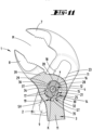
- the elastic return element 21, supported on the flank 18 of the longitudinal slot 9 causes a pivoting displacement of the hinge pin 4 in the direction of the tooth engagement, whereby the locking projection SV leaves the extension area 35 of the insertion opening 26 and steps in a locking manner in front of the surface surrounding the insertion opening 26 (locking part ST) (cf. Figures 9 and 20 ).
- the assembly is preferably carried out according to the keyhole principle.
- the end face 31 of the hinge pin 4 facing away from the collar portion 26 can be aligned with the surface of the fork portion 11 having the centering projection 15 facing away from the pliers leg 2.
- This bolt face 31 is preferably provided with a central bore-like recess 32 which accommodates the longitudinal axis x and in which the centering projection 15 is seated in the normal state of use of the pliers 1.
- the locking projection SV and the locking teeth 17 extend from the collar section 26 preferably only over a partial length of the hinge pin 4 viewed in the direction of the longitudinal axis x, so that an end region of the hinge pin 4 which interacts with a recess 33 surrounding the centering projection 15 and has the depression 32 is limited solely by the driving flanks 29 and 30 and the circular sections 28.
- the recess 33 is open towards the leg section 12 and can be designed with reference to a floor plan of the recess 33, for example according to Figure 11 have a circular contour over approximately 270 degrees, with a center point lying on the longitudinal axis x.
- the circular line K of this contour preferably has the same or approximately the same diameter as the insertion opening 27 of the receptacle 14. Over the remaining approximately 90 degrees, the recess forms a radially inward-pointing elevation 37, which forms a substantially straight driving shoulder 34, in particular in an area facing the driving flank 29.
- the leg wall covering the recess 33 axially outward forms a base 38 of the receptacle 14. Accordingly, the receptacle 14 is only accessible from one side (fork section 10 with insertion opening 27).
- the arrangement of the elevation 37 allows a relative pivoting displacement of the pliers leg 3 to the pliers leg 2.
- the hinge pin 4 is fixed in normal pliers use, so that the pliers leg 3 experiences a (overrunnable) stop limitation during the pivoting movement in the pliers jaw opening position, in that the driving shoulder 34 comes into contact with the driving flank 29 of the hinge pin 4 (cf. Figures 12 respectively 22).
- a pivoting displacement of the pliers leg 3 relative to the fixed pliers leg 2 about the longitudinal axis x of the hinge pin 4 is achievable.
- the jaws 7 and 8 are correspondingly in toothed engagement from a pliers jaw closed position (for example according to Figure 1 to 3 and 9 to 11 or 20 and 21) into a forceps-jaw open position according to Figures 12 or 22 and vice versa.
- the jaws of the pliers are preferably limited by a stop, for which purpose the depression 33 in the area of the elevation 37 forming the driving shoulder 34 can have a further shoulder directed in the circumferential direction opposite to the driving shoulder 34, possibly forming a stop shoulder 36.
- the driving flank 29 of the hinge pin 4 can come into contact with this shoulder in a stop-limiting manner.
- a stop limitation of the closed position by a stop is preferred.
- a jaw shoulder 39 connecting the fork sections 10 and 11 in the fork area 13 on the facing narrow surface of the leg section 12 of the fixed pliers leg 2 (see Figures 11 respectively 21).
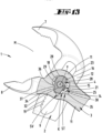
- the toothing can be removed solely by intentional influence on the toothing, after which the jaw width of the pliers can be changed by moving the movable pliers leg 3 together with the hinge pin 4 in the longitudinal slot 9 (cf. Figures 13 and 14 or 23 and 24).
- the joint pin 4 is dragged along rotating about the axis of rotation x via the driving formation 30 while resting on the driving counter-formation 31, which leads to a pivoting of the locking teeth 17 from the engagement position to the toothing 19 of the longitudinal slot 9 against the effect of the spring 18 with the ball 19 partially immersed in the bore 17.
- the movable pliers leg 3 is In this pivoting position it can be moved along the longitudinal slot 9 to change the jaw width.
- the rotational displacement of the pliers leg 3 beyond the pliers jaw opening position to remove the toothing engagement can take place over an angle of approximately 15 to 30 degrees.
- the toothing engagement can be removed from any locking position along the longitudinal slot 9.
- the selected rotational position for mounting the hinge pin 4 relative to the insertion opening 27 or the extension area 35 cannot be reached during normal use of the pliers 1.
- the stop-limited pivoting range of the movable pliers leg 3 relative to the fixed pliers leg 2 does not allow the hinge pin 4 to be dragged into the selected rotational position. Unwanted, accidental disassembly of the hinge pin 4 during normal handling of the pliers 1 is excluded. Disassembly of the hinge pin 4 without tools is also prevented.
- the locking projection 45 which, like the engagement projection 43, is aligned substantially radially to the longitudinal axis x, is further formed offset with respect to the longitudinal axis x of the hinge pin 4 in the opening pivot direction of the movable pliers leg 3 at a distance from the engagement projection 43, with a locking flank 46 aligned substantially radially to the longitudinal axis x.
- the radially outer end of the locking flank 46 can merge into an outer contour 47 formed in the form of a circular segment of the region of the movable pliers leg 3 surrounding the insertion opening 27.
- the movable jaw 8 is provided with a locking recess 48, which is open at the edge essentially in the direction of the movable pliers leg 3 and is spaced apart from the recess 44 in the direction of extension of the guide groove 40.
- This has an engagement flank 49 which is aligned essentially transversely to the longitudinal extension of the guide groove 40 or transversely to the sliding displacement direction of the movable jaw 8 on the fixed pliers leg 2 and which preferably merges into an essentially circular-segment-shaped contact flank 50 in the region of its end facing away from the longitudinal axis x of the hinge pin 4.
- both the locking projection 45 and the corresponding locking recess 48 are provided only on one side of the fork-shaped movable jaw 8 which overlaps the bearing plate of the fixed pliers leg 2 as well as of the movable pliers leg 3, more preferably on the side of the leg which also has the insertion opening 27 for the hinge pin 4.
- the movable jaw 8 can thus also be displaced in this predetermined pivoting position of the movable pliers leg 3 alone together with the movable pliers leg 3 along the guide groove 40 to change the jaw width.
Landscapes
- Engineering & Computer Science (AREA)
- Mechanical Engineering (AREA)
- Gripping Jigs, Holding Jigs, And Positioning Jigs (AREA)
- Hand Tools For Fitting Together And Separating, Or Other Hand Tools (AREA)
Claims (15)
- Pince (1) avec deux branches de pince (2, 3) se croisant dans un axe d'articulation (4), dont l'une est mobile et l'autre fixe, des sections de poignée étant formées d'un côté de l'axe d'articulation (4) et des mâchoires (7, 8) coopérant comme mâchoire de pince (M) étant formées de l'autre côté de l'axe d'articulation (4), la branche fixe (2) de la pince présentant en outre une fente longitudinale (9) avec une denture (19) et le boulon d'articulation (4) se trouvant dans un logement (14) pouvant être déplacé autour de son axe longitudinal (x) dans une position de libération à partir d'un engrènement de denture contre la force d'un ressort (22) et à l'aide d'une saillie de blocage (SV), qui coopère avec une partie de blocage (ST) du logement (14), est maintenu dans la direction de l'axe longitudinal (x), caractérisé en ce que la saillie de blocage (SV) et la partie de blocage (ST) sont conçues pour déborder l'une sur l'autre au cours d'un montage, l'effet du ressort (22) étant surmonté.
- Pince (1) selon la revendication 1, caractérisée en ce que l'axe d'articulation (4) comporte le ressort (22).
- Pince (1) avec deux branches de pince (2, 3) se croisant dans un axe d'articulation (4), dont l'une est mobile et l'autre fixe, des sections de poignée étant formées sur un côté de l'axe d'articulation (4) et des mâchoires (7, 8) coopérant en tant que mâchoire de pince (M) étant formées sur l'autre côté de l'axe d'articulation (4), la branche fixe (2) de la pince présentant en outre une fente longitudinale (9) avec une denture (19) et l'axe d'articulation (4) se trouvant dans un logement (14) pouvant être déplacé autour de son axe longitudinal (x) dans une position de libération à partir d'un engrènement de denture contre la force d'un ressort (22), ou Pince selon la revendication 1, caractérisée en ce que le logement (14) est formé avec un fond (38) sur la branche mobile (3) de la pince.
- Pince selon la revendication 3, caractérisée en ce que le fond (38) est formé d'un seul matériau avec la branche (3) de la pince.
- Pince selon l'une des revendications 3 ou 4, caractérisée en ce que l'axe d'articulation (4) est maintenu en direction de l'axe longitudinal (x) à l'aide d'une protubérance de blocage (SV) coopérant avec une partie de blocage (ST) du logement (14).
- Pince selon l'une des revendications précédentes, caractérisée en ce que le ressort (22) empêche d'atteindre la ou une position de montage lorsque la pince (1) est montée.
- Pince selon l'une des revendications 1 ou 2, caractérisée en ce que le logement (14) est formé dans la branche mobile (3) de la pince.
- Pince selon l'une des revendications 1, 2 ou 5, caractérisée en ce que la saillie de blocage (SV) coopère avec une surface intérieure du logement (14) tournée vers la branche fixe (2) de la pince.
- Pince selon l'une des revendications précédentes, caractérisée en ce que le logement (14) comporte une ouverture d'insertion (27) avec une zone d'élargissement (35).
- Pince selon la revendication 9, caractérisée en ce que la zone d'extension (35) peut être traversée par la saillie de blocage (SV).
- Pince selon l'une des revendications 10, caractérisée en ce que l'axe d'articulation (4) doit être placé dans une position de rotation choisie par rapport à son axe longitudinal (x) et à l'extension de la fente longitudinale (9) pour traverser l'ouverture d'insertion (27).
- Pince selon l'une des revendications précédentes, caractérisée en ce que l'axe d'articulation (4) présente un élément de rappel élastique (21), pour la précontrainte dans l'engrènement de la denture, où, de préférence, l'élément de rappel élastique (21) est déplacé dans une position de compression déterminée au cours du passage dans la position de rotation sélectionnée et/ou la position de compression déterminée ne peut pas être atteinte lors de l'utilisation habituelle de la pince (1).
- Pince selon l'une des revendications précédentes, caractérisée en ce que l'axe d'articulation (4) est reçu dans une section du logement (14) qui n'est que partiellement circulaire et qui présente un épaulement d'entraînement (34) différent d'un tracé circulaire, pour coopérer avec un flanc d'entraînement (29) de l'axe d'articulation (4), l'axe d'articulation (4) étant guidé en rotation dans un renfoncement circulaire (33) du logement (14) et une ligne circulaire étant prédéfinie par le renfoncement circulaire (33), l'épaulement d'entraînement (34) faisant saillie radialement vers l'intérieur par rapport à la ligne circulaire (K) et le flanc d'entraînement (29) étant également formé à l'intérieur de la ligne circulaire (K), le renfoncement (33) étant, de préférence, circulaire par sections.
- Pince avec une branche de pince mobile (3) et une branche de pince fixe (2), la branche de pince fixe (2) présentant une mâchoire (7) reliée de manière fixe, une mâchoire (8) mobile sur la branche de pince fixe (2) pouvant en outre être déplacée de manière guidée au moyen de la branche de pince mobile (3), la branche de pince mobile (3) pouvant en outre être déplacée pour modifier la largeur d'ouverture des mâchoires (7, 8) et coopère, par l'intermédiaire d'un axe d'articulation (4) prévu sur cette branche de pince (3) dans la zone de son axe de rotation (x) et présentant une dent de blocage (17), avec une fente longitudinale (9) présentant une denture (19), selon une liaison par la forme détachable, et la branche mobile (3) de la pince s'engageant avec la mâchoire mobile (8) par l'intermédiaire d'une saillie d'engagement (43) prévue sur cette branche (3) de la pince, qui s'engage dans un évidement (44) prévu sur la mâchoire mobile (8), une saillie de blocage (45) étant en outre formée sur la branche mobile (3) de la pince, laquelle est en prise avec la mâchoire mobile (8) dans une position de pivotement prédéfinie de la branche mobile (3) de la pince et s'oppose ainsi à un éventuel mouvement d'évitement de la mâchoire mobile (8) par rapport à la branche mobile (3) de la pince, caractérisé en ce que la saillie de blocage (45) est formée sur la branche mobile (3) de la pince, en ce que, en outre, la saillie de blocage (45) est réalisée décalée par rapport à l'axe de rotation (x) de l'axe d'articulation (4) dans une direction de pivotement d'ouverture de la branche mobile (3) de la pince, à distance de la saillie d'engagement (43), la saillie de blocage (45) étant orientée, comme la saillie d'engagement (43), sensiblement radialement par rapport à l'axe de rotation (x), et en ce que la saillie de blocage (45) présente un flanc de blocage (46) orienté sensiblement radialement par rapport à l'axe de rotation (x).
- Pince selon la revendication 14, caractérisée en ce que la mâchoire mobile (8) présente un flanc d'engagement (49) qui, dans la position de pivotement prédéfinie de la branche mobile (3) de la pince, est sollicité par la saillie de blocage (45), où, de préférence, le flanc d'engagement (49) fait partie d'un évidement de blocage (48) dans lequel la saillie de blocage (45) s'insère dans la position de pivotement prédéterminée de la branche mobile (3) de la pince et/ou la position de pivotement prédéterminée de la branche mobile (3) de la pince correspond à la position d'ouverture de la pince (1).
Applications Claiming Priority (3)
| Application Number | Priority Date | Filing Date | Title |
|---|---|---|---|
| DE102020103646 | 2020-02-12 | ||
| DE102021102330.0A DE102021102330A1 (de) | 2020-02-12 | 2021-02-02 | Zange |
| PCT/EP2021/053056 WO2021160598A1 (fr) | 2020-02-12 | 2021-02-09 | Pince |
Publications (2)
| Publication Number | Publication Date |
|---|---|
| EP4103357A1 EP4103357A1 (fr) | 2022-12-21 |
| EP4103357B1 true EP4103357B1 (fr) | 2024-08-21 |
Family
ID=76968913
Family Applications (1)
| Application Number | Title | Priority Date | Filing Date |
|---|---|---|---|
| EP21704745.5A Active EP4103357B1 (fr) | 2020-02-12 | 2021-02-09 | Pince |
Country Status (9)
| Country | Link |
|---|---|
| US (1) | US12246420B2 (fr) |
| EP (1) | EP4103357B1 (fr) |
| JP (1) | JP7660579B2 (fr) |
| CN (1) | CN115103740A (fr) |
| DE (1) | DE102021102330A1 (fr) |
| ES (1) | ES2991482T3 (fr) |
| PL (1) | PL4103357T3 (fr) |
| TW (1) | TWI887356B (fr) |
| WO (1) | WO2021160598A1 (fr) |
Families Citing this family (3)
| Publication number | Priority date | Publication date | Assignee | Title |
|---|---|---|---|---|
| USD985345S1 (en) * | 2021-03-31 | 2023-05-09 | Knipex-Werk C. Gustav Putsch Kg | Scissors |
| CN118284494A (zh) | 2021-11-08 | 2024-07-02 | 科尼佩克斯-沃克·C·古斯塔夫普奇公司 | 手持工具和用于与手持工具的把手区域卡锁连接的功能部件 |
| TWI884854B (zh) * | 2024-08-20 | 2025-05-21 | 伯鑫工具股份有限公司 | 水管鉗 |
Citations (5)
| Publication number | Priority date | Publication date | Assignee | Title |
|---|---|---|---|---|
| DE3929323C2 (de) * | 1989-09-04 | 2001-07-05 | Putsch Gustav Knipex Werk | Schlüsselzange |
| DE10343412A1 (de) * | 2003-05-22 | 2004-12-09 | Knipex-Werk C. Gustav Putsch Kg | Einhandbetätigbare Zange |
| DE102007049032A1 (de) * | 2006-10-24 | 2008-04-30 | Knipex-Werk C. Gustav Putsch Kg | Zange |
| DE102015110060A1 (de) * | 2015-06-23 | 2016-12-29 | Orbis Will Gmbh + Co. Kg | Zange mit zwei sich in einem Gelenkbolzen kreuzenden Zangenschenkeln |
| DE102018110106A1 (de) * | 2018-04-26 | 2019-10-31 | Knipex-Werk C. Gustav Putsch Kg | Zange |
Family Cites Families (7)
| Publication number | Priority date | Publication date | Assignee | Title |
|---|---|---|---|---|
| DE19806653A1 (de) * | 1998-02-18 | 1999-08-19 | Wegerhoff H Alarm Werkzeug | Rohrzange |
| DE10042288A1 (de) * | 2000-08-29 | 2002-03-14 | Erdmeier Hans Udo | Greifzangenschlüssel mit verstellbarer Maulweite |
| JP4490972B2 (ja) * | 2003-05-22 | 2010-06-30 | クニペックス−ウエルク・ツエ・グスタフ・プッチュ・カーゲー | 片手で操作できるペンチ |
| CN101432100A (zh) * | 2006-01-24 | 2009-05-13 | I.D.L.科技工具有限责任公司 | 自动调整钳 |
| DE202011050505U1 (de) * | 2011-06-20 | 2011-08-22 | Eduard Wille Gmbh & Co. Kg | Rohr- bzw. Wasserpumpenzange |
| ES2536607T3 (es) | 2011-11-23 | 2015-05-26 | Sna Europe Industries Sa | Mecanismo de palanca para tenaza ajustable |
| US9676082B1 (en) * | 2016-03-14 | 2017-06-13 | John Schoolland | Fastener removal tool |
-
2021
- 2021-02-02 DE DE102021102330.0A patent/DE102021102330A1/de not_active Withdrawn
- 2021-02-09 ES ES21704745T patent/ES2991482T3/es active Active
- 2021-02-09 US US17/797,813 patent/US12246420B2/en active Active
- 2021-02-09 EP EP21704745.5A patent/EP4103357B1/fr active Active
- 2021-02-09 PL PL21704745.5T patent/PL4103357T3/pl unknown
- 2021-02-09 CN CN202180013433.9A patent/CN115103740A/zh active Pending
- 2021-02-09 JP JP2022547673A patent/JP7660579B2/ja active Active
- 2021-02-09 WO PCT/EP2021/053056 patent/WO2021160598A1/fr not_active Ceased
- 2021-02-17 TW TW110105278A patent/TWI887356B/zh active
Patent Citations (5)
| Publication number | Priority date | Publication date | Assignee | Title |
|---|---|---|---|---|
| DE3929323C2 (de) * | 1989-09-04 | 2001-07-05 | Putsch Gustav Knipex Werk | Schlüsselzange |
| DE10343412A1 (de) * | 2003-05-22 | 2004-12-09 | Knipex-Werk C. Gustav Putsch Kg | Einhandbetätigbare Zange |
| DE102007049032A1 (de) * | 2006-10-24 | 2008-04-30 | Knipex-Werk C. Gustav Putsch Kg | Zange |
| DE102015110060A1 (de) * | 2015-06-23 | 2016-12-29 | Orbis Will Gmbh + Co. Kg | Zange mit zwei sich in einem Gelenkbolzen kreuzenden Zangenschenkeln |
| DE102018110106A1 (de) * | 2018-04-26 | 2019-10-31 | Knipex-Werk C. Gustav Putsch Kg | Zange |
Also Published As
| Publication number | Publication date |
|---|---|
| JP2023525948A (ja) | 2023-06-20 |
| CN115103740A (zh) | 2022-09-23 |
| TW202135987A (zh) | 2021-10-01 |
| JP7660579B2 (ja) | 2025-04-11 |
| ES2991482T3 (es) | 2024-12-03 |
| EP4103357A1 (fr) | 2022-12-21 |
| DE102021102330A1 (de) | 2021-08-12 |
| WO2021160598A1 (fr) | 2021-08-19 |
| PL4103357T3 (pl) | 2025-01-13 |
| US12246420B2 (en) | 2025-03-11 |
| TWI887356B (zh) | 2025-06-21 |
| US20230074435A1 (en) | 2023-03-09 |
Similar Documents
| Publication | Publication Date | Title |
|---|---|---|
| EP1649981B1 (fr) | Pince de sertissage | |
| EP4103357B1 (fr) | Pince | |
| EP2773490B1 (fr) | Pince | |
| EP1199020A2 (fr) | Charnière pour siège de toilette | |
| DE29522206U1 (de) | Bohrfutter | |
| EP3313619B1 (fr) | Pince munie de deux branches se croisant dans un tourillon d'articulation | |
| EP1208949A2 (fr) | Outil de sertissage | |
| EP3784439B1 (fr) | Pince | |
| EP2873381A1 (fr) | Instrument médical de type pince | |
| WO2016146272A1 (fr) | Élément de maintien pour une poignée de porte ou de fenêtre et agencement d'une poignée de porte ou de fenêtre au niveau d'une ouverture de réception d'un cadre de fenêtre, d'un battant de porte ou similaire | |
| DE10162861B4 (de) | Hebelzwinge | |
| EP2636489B1 (fr) | Pince avec levier d'actionnement | |
| AT520631B1 (de) | Halter für eine Tauchform | |
| EP2080592A1 (fr) | Anneau de serrage et pince pour l'utilisation d'un tel anneau de serrage | |
| DE69416082T2 (de) | Scharniersatz | |
| WO2009049712A1 (fr) | Fermeture à compression | |
| DE3219011C2 (fr) | ||
| EP0298270B1 (fr) | Outil tel qu'un outil de jardinage, d'agriculture, de nettoyage ou similaire | |
| DE102006022999A1 (de) | Zange | |
| EP2252435B1 (fr) | Pince pouvant être actionnée d'une seule main | |
| DE10044874A1 (de) | Schlüsselzange | |
| EP3826811B1 (fr) | Logement d'outil et machine-outil manuelle | |
| DE202008001949U1 (de) | Greifzange | |
| EP3565773B1 (fr) | Raclette de convoyeur à chaîne repliable | |
| EP3636863A1 (fr) | Fixation de joint |
Legal Events
| Date | Code | Title | Description |
|---|---|---|---|
| STAA | Information on the status of an ep patent application or granted ep patent |
Free format text: STATUS: UNKNOWN |
|
| STAA | Information on the status of an ep patent application or granted ep patent |
Free format text: STATUS: THE INTERNATIONAL PUBLICATION HAS BEEN MADE |
|
| PUAI | Public reference made under article 153(3) epc to a published international application that has entered the european phase |
Free format text: ORIGINAL CODE: 0009012 |
|
| STAA | Information on the status of an ep patent application or granted ep patent |
Free format text: STATUS: REQUEST FOR EXAMINATION WAS MADE |
|
| 17P | Request for examination filed |
Effective date: 20220902 |
|
| AK | Designated contracting states |
Kind code of ref document: A1 Designated state(s): AL AT BE BG CH CY CZ DE DK EE ES FI FR GB GR HR HU IE IS IT LI LT LU LV MC MK MT NL NO PL PT RO RS SE SI SK SM TR |
|
| DAV | Request for validation of the european patent (deleted) | ||
| DAX | Request for extension of the european patent (deleted) | ||
| STAA | Information on the status of an ep patent application or granted ep patent |
Free format text: STATUS: EXAMINATION IS IN PROGRESS |
|
| 17Q | First examination report despatched |
Effective date: 20230905 |
|
| GRAP | Despatch of communication of intention to grant a patent |
Free format text: ORIGINAL CODE: EPIDOSNIGR1 |
|
| STAA | Information on the status of an ep patent application or granted ep patent |
Free format text: STATUS: GRANT OF PATENT IS INTENDED |
|
| INTG | Intention to grant announced |
Effective date: 20240408 |
|
| GRAS | Grant fee paid |
Free format text: ORIGINAL CODE: EPIDOSNIGR3 |
|
| GRAA | (expected) grant |
Free format text: ORIGINAL CODE: 0009210 |
|
| STAA | Information on the status of an ep patent application or granted ep patent |
Free format text: STATUS: THE PATENT HAS BEEN GRANTED |
|
| AK | Designated contracting states |
Kind code of ref document: B1 Designated state(s): AL AT BE BG CH CY CZ DE DK EE ES FI FR GB GR HR HU IE IS IT LI LT LU LV MC MK MT NL NO PL PT RO RS SE SI SK SM TR |
|
| REG | Reference to a national code |
Ref country code: GB Ref legal event code: FG4D Free format text: NOT ENGLISH |
|
| REG | Reference to a national code |
Ref country code: CH Ref legal event code: EP |
|
| REG | Reference to a national code |
Ref country code: DE Ref legal event code: R096 Ref document number: 502021004860 Country of ref document: DE |
|
| REG | Reference to a national code |
Ref country code: IE Ref legal event code: FG4D Free format text: LANGUAGE OF EP DOCUMENT: GERMAN |
|
| REG | Reference to a national code |
Ref country code: ES Ref legal event code: FG2A Ref document number: 2991482 Country of ref document: ES Kind code of ref document: T3 Effective date: 20241203 |
|
| REG | Reference to a national code |
Ref country code: LT Ref legal event code: MG9D |
|
| P01 | Opt-out of the competence of the unified patent court (upc) registered |
Free format text: CASE NUMBER: APP_59944/2024 Effective date: 20241106 |
|
| REG | Reference to a national code |
Ref country code: NL Ref legal event code: MP Effective date: 20240821 |
|
| PG25 | Lapsed in a contracting state [announced via postgrant information from national office to epo] |
Ref country code: NO Free format text: LAPSE BECAUSE OF FAILURE TO SUBMIT A TRANSLATION OF THE DESCRIPTION OR TO PAY THE FEE WITHIN THE PRESCRIBED TIME-LIMIT Effective date: 20241121 |
|
| PG25 | Lapsed in a contracting state [announced via postgrant information from national office to epo] |
Ref country code: PT Free format text: LAPSE BECAUSE OF FAILURE TO SUBMIT A TRANSLATION OF THE DESCRIPTION OR TO PAY THE FEE WITHIN THE PRESCRIBED TIME-LIMIT Effective date: 20241223 Ref country code: NL Free format text: LAPSE BECAUSE OF FAILURE TO SUBMIT A TRANSLATION OF THE DESCRIPTION OR TO PAY THE FEE WITHIN THE PRESCRIBED TIME-LIMIT Effective date: 20240821 Ref country code: GR Free format text: LAPSE BECAUSE OF FAILURE TO SUBMIT A TRANSLATION OF THE DESCRIPTION OR TO PAY THE FEE WITHIN THE PRESCRIBED TIME-LIMIT Effective date: 20241122 Ref country code: FI Free format text: LAPSE BECAUSE OF FAILURE TO SUBMIT A TRANSLATION OF THE DESCRIPTION OR TO PAY THE FEE WITHIN THE PRESCRIBED TIME-LIMIT Effective date: 20240821 |
|
| PG25 | Lapsed in a contracting state [announced via postgrant information from national office to epo] |
Ref country code: BG Free format text: LAPSE BECAUSE OF FAILURE TO SUBMIT A TRANSLATION OF THE DESCRIPTION OR TO PAY THE FEE WITHIN THE PRESCRIBED TIME-LIMIT Effective date: 20240821 |
|
| PG25 | Lapsed in a contracting state [announced via postgrant information from national office to epo] |
Ref country code: LV Free format text: LAPSE BECAUSE OF FAILURE TO SUBMIT A TRANSLATION OF THE DESCRIPTION OR TO PAY THE FEE WITHIN THE PRESCRIBED TIME-LIMIT Effective date: 20240821 |
|
| PG25 | Lapsed in a contracting state [announced via postgrant information from national office to epo] |
Ref country code: IS Free format text: LAPSE BECAUSE OF FAILURE TO SUBMIT A TRANSLATION OF THE DESCRIPTION OR TO PAY THE FEE WITHIN THE PRESCRIBED TIME-LIMIT Effective date: 20241221 |
|
| PG25 | Lapsed in a contracting state [announced via postgrant information from national office to epo] |
Ref country code: HR Free format text: LAPSE BECAUSE OF FAILURE TO SUBMIT A TRANSLATION OF THE DESCRIPTION OR TO PAY THE FEE WITHIN THE PRESCRIBED TIME-LIMIT Effective date: 20240821 |
|
| PG25 | Lapsed in a contracting state [announced via postgrant information from national office to epo] |
Ref country code: RS Free format text: LAPSE BECAUSE OF FAILURE TO SUBMIT A TRANSLATION OF THE DESCRIPTION OR TO PAY THE FEE WITHIN THE PRESCRIBED TIME-LIMIT Effective date: 20241121 |
|
| PG25 | Lapsed in a contracting state [announced via postgrant information from national office to epo] |
Ref country code: RS Free format text: LAPSE BECAUSE OF FAILURE TO SUBMIT A TRANSLATION OF THE DESCRIPTION OR TO PAY THE FEE WITHIN THE PRESCRIBED TIME-LIMIT Effective date: 20241121 Ref country code: PT Free format text: LAPSE BECAUSE OF FAILURE TO SUBMIT A TRANSLATION OF THE DESCRIPTION OR TO PAY THE FEE WITHIN THE PRESCRIBED TIME-LIMIT Effective date: 20241223 Ref country code: NO Free format text: LAPSE BECAUSE OF FAILURE TO SUBMIT A TRANSLATION OF THE DESCRIPTION OR TO PAY THE FEE WITHIN THE PRESCRIBED TIME-LIMIT Effective date: 20241121 Ref country code: NL Free format text: LAPSE BECAUSE OF FAILURE TO SUBMIT A TRANSLATION OF THE DESCRIPTION OR TO PAY THE FEE WITHIN THE PRESCRIBED TIME-LIMIT Effective date: 20240821 Ref country code: LV Free format text: LAPSE BECAUSE OF FAILURE TO SUBMIT A TRANSLATION OF THE DESCRIPTION OR TO PAY THE FEE WITHIN THE PRESCRIBED TIME-LIMIT Effective date: 20240821 Ref country code: IS Free format text: LAPSE BECAUSE OF FAILURE TO SUBMIT A TRANSLATION OF THE DESCRIPTION OR TO PAY THE FEE WITHIN THE PRESCRIBED TIME-LIMIT Effective date: 20241221 Ref country code: HR Free format text: LAPSE BECAUSE OF FAILURE TO SUBMIT A TRANSLATION OF THE DESCRIPTION OR TO PAY THE FEE WITHIN THE PRESCRIBED TIME-LIMIT Effective date: 20240821 Ref country code: GR Free format text: LAPSE BECAUSE OF FAILURE TO SUBMIT A TRANSLATION OF THE DESCRIPTION OR TO PAY THE FEE WITHIN THE PRESCRIBED TIME-LIMIT Effective date: 20241122 Ref country code: FI Free format text: LAPSE BECAUSE OF FAILURE TO SUBMIT A TRANSLATION OF THE DESCRIPTION OR TO PAY THE FEE WITHIN THE PRESCRIBED TIME-LIMIT Effective date: 20240821 Ref country code: BG Free format text: LAPSE BECAUSE OF FAILURE TO SUBMIT A TRANSLATION OF THE DESCRIPTION OR TO PAY THE FEE WITHIN THE PRESCRIBED TIME-LIMIT Effective date: 20240821 |
|
| PG25 | Lapsed in a contracting state [announced via postgrant information from national office to epo] |
Ref country code: DK Free format text: LAPSE BECAUSE OF FAILURE TO SUBMIT A TRANSLATION OF THE DESCRIPTION OR TO PAY THE FEE WITHIN THE PRESCRIBED TIME-LIMIT Effective date: 20240821 Ref country code: RO Free format text: LAPSE BECAUSE OF FAILURE TO SUBMIT A TRANSLATION OF THE DESCRIPTION OR TO PAY THE FEE WITHIN THE PRESCRIBED TIME-LIMIT Effective date: 20240821 Ref country code: SM Free format text: LAPSE BECAUSE OF FAILURE TO SUBMIT A TRANSLATION OF THE DESCRIPTION OR TO PAY THE FEE WITHIN THE PRESCRIBED TIME-LIMIT Effective date: 20240821 |
|
| PG25 | Lapsed in a contracting state [announced via postgrant information from national office to epo] |
Ref country code: EE Free format text: LAPSE BECAUSE OF FAILURE TO SUBMIT A TRANSLATION OF THE DESCRIPTION OR TO PAY THE FEE WITHIN THE PRESCRIBED TIME-LIMIT Effective date: 20240821 |
|
| PGFP | Annual fee paid to national office [announced via postgrant information from national office to epo] |
Ref country code: AT Payment date: 20250417 Year of fee payment: 5 |
|
| PG25 | Lapsed in a contracting state [announced via postgrant information from national office to epo] |
Ref country code: CZ Free format text: LAPSE BECAUSE OF FAILURE TO SUBMIT A TRANSLATION OF THE DESCRIPTION OR TO PAY THE FEE WITHIN THE PRESCRIBED TIME-LIMIT Effective date: 20240821 |
|
| PG25 | Lapsed in a contracting state [announced via postgrant information from national office to epo] |
Ref country code: SK Free format text: LAPSE BECAUSE OF FAILURE TO SUBMIT A TRANSLATION OF THE DESCRIPTION OR TO PAY THE FEE WITHIN THE PRESCRIBED TIME-LIMIT Effective date: 20240821 |
|
| REG | Reference to a national code |
Ref country code: DE Ref legal event code: R097 Ref document number: 502021004860 Country of ref document: DE |
|
| PLBE | No opposition filed within time limit |
Free format text: ORIGINAL CODE: 0009261 |
|
| STAA | Information on the status of an ep patent application or granted ep patent |
Free format text: STATUS: NO OPPOSITION FILED WITHIN TIME LIMIT |
|
| 26N | No opposition filed |
Effective date: 20250522 |
|
| PG25 | Lapsed in a contracting state [announced via postgrant information from national office to epo] |
Ref country code: SE Free format text: LAPSE BECAUSE OF FAILURE TO SUBMIT A TRANSLATION OF THE DESCRIPTION OR TO PAY THE FEE WITHIN THE PRESCRIBED TIME-LIMIT Effective date: 20240821 |
|
| PG25 | Lapsed in a contracting state [announced via postgrant information from national office to epo] |
Ref country code: MC Free format text: LAPSE BECAUSE OF FAILURE TO SUBMIT A TRANSLATION OF THE DESCRIPTION OR TO PAY THE FEE WITHIN THE PRESCRIBED TIME-LIMIT Effective date: 20240821 |
|
| REG | Reference to a national code |
Ref country code: CH Ref legal event code: PL |
|
| PG25 | Lapsed in a contracting state [announced via postgrant information from national office to epo] |
Ref country code: LU Free format text: LAPSE BECAUSE OF NON-PAYMENT OF DUE FEES Effective date: 20250209 |
|
| PG25 | Lapsed in a contracting state [announced via postgrant information from national office to epo] |
Ref country code: CH Free format text: LAPSE BECAUSE OF NON-PAYMENT OF DUE FEES Effective date: 20250228 |
|
| REG | Reference to a national code |
Ref country code: BE Ref legal event code: MM Effective date: 20250228 |
|
| PG25 | Lapsed in a contracting state [announced via postgrant information from national office to epo] |
Ref country code: BE Free format text: LAPSE BECAUSE OF NON-PAYMENT OF DUE FEES Effective date: 20250228 |
|
| PG25 | Lapsed in a contracting state [announced via postgrant information from national office to epo] |
Ref country code: IE Free format text: LAPSE BECAUSE OF NON-PAYMENT OF DUE FEES Effective date: 20250209 |
|
| PGFP | Annual fee paid to national office [announced via postgrant information from national office to epo] |
Ref country code: GB Payment date: 20260218 Year of fee payment: 6 |
|
| PGFP | Annual fee paid to national office [announced via postgrant information from national office to epo] |
Ref country code: ES Payment date: 20260310 Year of fee payment: 6 |
|
| PGFP | Annual fee paid to national office [announced via postgrant information from national office to epo] |
Ref country code: DE Payment date: 20260219 Year of fee payment: 6 |
|
| PGFP | Annual fee paid to national office [announced via postgrant information from national office to epo] |
Ref country code: IT Payment date: 20260225 Year of fee payment: 6 |
|
| PGFP | Annual fee paid to national office [announced via postgrant information from national office to epo] |
Ref country code: FR Payment date: 20260218 Year of fee payment: 6 |
|
| PGFP | Annual fee paid to national office [announced via postgrant information from national office to epo] |
Ref country code: PL Payment date: 20260115 Year of fee payment: 6 |