EP2873381A1 - Instrument médical de type pince - Google Patents
Instrument médical de type pince Download PDFInfo
- Publication number
- EP2873381A1 EP2873381A1 EP20140003803 EP14003803A EP2873381A1 EP 2873381 A1 EP2873381 A1 EP 2873381A1 EP 20140003803 EP20140003803 EP 20140003803 EP 14003803 A EP14003803 A EP 14003803A EP 2873381 A1 EP2873381 A1 EP 2873381A1
- Authority
- EP
- European Patent Office
- Prior art keywords
- guide plate
- bearing
- bearing plate
- plate
- recess
- Prior art date
- Legal status (The legal status is an assumption and is not a legal conclusion. Google has not performed a legal analysis and makes no representation as to the accuracy of the status listed.)
- Withdrawn
Links
- 238000004140 cleaning Methods 0.000 claims abstract description 49
- 125000006850 spacer group Chemical group 0.000 claims abstract description 18
- 230000004323 axial length Effects 0.000 claims description 4
- 239000012530 fluid Substances 0.000 description 6
- 238000010276 construction Methods 0.000 description 5
- 230000007704 transition Effects 0.000 description 4
- 239000007788 liquid Substances 0.000 description 3
- 238000007373 indentation Methods 0.000 description 2
- 239000003599 detergent Substances 0.000 description 1
- 238000006073 displacement reaction Methods 0.000 description 1
- 238000011010 flushing procedure Methods 0.000 description 1
- 238000003780 insertion Methods 0.000 description 1
- 230000037431 insertion Effects 0.000 description 1
- 238000010926 purge Methods 0.000 description 1
Images


Classifications
-
- A—HUMAN NECESSITIES
- A61—MEDICAL OR VETERINARY SCIENCE; HYGIENE
- A61B—DIAGNOSIS; SURGERY; IDENTIFICATION
- A61B17/00—Surgical instruments, devices or methods
- A61B17/28—Surgical forceps
- A61B17/2812—Surgical forceps with a single pivotal connection
- A61B17/2816—Pivots
-
- A—HUMAN NECESSITIES
- A61—MEDICAL OR VETERINARY SCIENCE; HYGIENE
- A61B—DIAGNOSIS; SURGERY; IDENTIFICATION
- A61B90/00—Instruments, implements or accessories specially adapted for surgery or diagnosis and not covered by any of the groups A61B1/00 - A61B50/00, e.g. for luxation treatment or for protecting wound edges
- A61B90/08—Accessories or related features not otherwise provided for
- A61B2090/0813—Accessories designed for easy sterilising, i.e. re-usable
Definitions
- the invention relates to a medical instrument consisting of a first, a guide plate having hand lever and a second, a bearing plate having hand lever which are pivotally connected to one another via a bearing pin in the region of the guide plate and the bearing plate and provided with a radially enlarged head portion, wherein the Bearing plate in each case forms a receiving groove in their longitudinal edge areas, in which engages the guide plate in its operating position.
- Pliers or scissors-like medical instruments having a first hand lever having a guide plate and a second hand lever having a bearing plate have been known for some time. To this is exemplary on the DE 20 2011 107 977 U1 as well as on the DE 20 2010 010 843 U1 directed.
- the objects of these two publications are concerned with being able to clean such a medical instrument or even a hand tool without the two hand levers having to be separated from one another, that is, without the instrument or hand tool having to be disassembled.
- the two hand lever each have a tool part and a handle part. Between the tool part and the handle part is in each case a "plate-like" Middle section provided, which can also be referred to as a guide plate and bearing plate.
- a bearing journal is provided, essentially centrally, which has a radially enlarged head part.
- the bearing plate has a considerably smaller thickness than the tool part and as the handle part. In this case, the bearing plate is offset in the direction of the bearing pin arranged to the tool part and the handle part, so that the tool part and the handle part protrudes in the direction of the bearing pin "upwards" on the bearing plate.
- the guide plate with its tool part and its handle part in the direction of the journal in the normal operating state are provided in the transition to the tool part and in the transition region to the handle portion parallel to the bearing plate extending grooves in the tool part and the handle portion lying end portions of the bearing plate , in which the guide plate engages in the normal operating state.
- the guide plate with its bearing plate side, flat contact surface lies flat on the guide plate side "sliding surface" of the bearing plate.
- the two hand lever are not axially adjustable in the normal operating state in the direction of the journal.
- the axial length of the journal is the subject of the DE 20 2010 010 843 U1 chosen such that its radially expanded head part in the normal operating state has a distance "outwards" to the guide plate, which corresponds to at least twice the thickness of the guide plate.
- the guide plate arrives after a predetermined angle of rotation with the grooves of the bearing plate except Engaging so that the guide plate can be adjusted along the journal.
- the axial travel is limited by the radially expanded head. Due to this configuration, thus the contact surface of the guide plate and the sliding surface of the bearing plate are freely accessible, so that the hand tool or medical instrument after the DE 20 2010 010 843 U1 can be cleaned with a cleaning fluid.
- a disadvantage of this construction is that the length of the journal is chosen such that the guide plate can come to rest on the outside in the area of the tool part and in the region of the handle part after full axial adjustment and subsequent further pivotal movement of the guide plate relative to the hand lever with the bearing plate.
- the contact surface of the guide plate is covered here again in case of improper handling for cleaning, so that a safe cleaning can not be guaranteed.
- the guide plate and the bearing plate are designed somewhat differently.
- the bearing plate has no receiving grooves in the transition region of the tool part to the bearing plate or in the transition region of the handle part to the bearing plate.
- a slot-like opening is provided, which in its one end region has a radially enlarged depression with a small depth.
- a second, radially enlarged recess is provided, whose depth is greater than the depth of the first recess in the first end portion of the slot-like opening.
- the diameter of the two radially enlarged depressions is matched to the diameter of the radially expanded head portion of the bearing journal, so that the head portion of the bearing journal is selectively engageable with one of the depressions form-fitting and rotatable in engagement.
- the bearing pin is also in this construction, in turn, centrally and fixedly arranged in the bearing plate.
- the bearing plate In order to be able to disengage the head part of the bearing journal with the first depression of lesser depth, the bearing plate has a transverse groove running transversely to the bearing plate on its sliding surface facing the guide plate.
- the width of this transverse groove is at least as large as the width of the guide plate.
- the guide plate with its slot-like breakthrough along the journal can be adjusted axially into this transverse groove.
- the first depression of lesser depth with the radially enlarged head portion of the journal is disengaged.
- the guide plate be adjusted with their slot-like opening transversely to the bearing pin until the breakthrough comes with its second radially enlarged depression greater depth with the radially expanded head portion of the journal into coincidence.
- the head part engages with the second depression of greater depth.
- the guide plate to the bearing plate has a predefined distance. This ensures regardless of a subsequent change in the angular position of the guide plate to the bearing plate or the two levers to each other that the two contact surface of the guide plate and the sliding surface of the bearing plate always have a distance from each other, unless the guide plate unintentionally back in the direction of the journal axially the bearing plate is to be distorted.
- a plate spring may be provided in the vicinity of the journal, through which this distance is held resiliently.
- the head part of the bearing pin for adjusting the cleaning position can be disengaged only by the action of force with the first radially enlarged depression. Conversely, this is necessary when returning to the normal operating position.
- the force can be relatively large, so that the handling of this medical instrument with respect to the adjustment of the two hand lever from the normal operating position to the cleaning position and vice versa right is expensive.
- the head part of the journal serves as a pivot bearing, for which purpose the head part has on the underside a circumferential conical surface, which optionally engage in corresponding, partially circumferential conical surfaces of the two depressions in the operating position or in the cleaning position.
- the invention has for its object to improve a forceps-like medical instrument such that a cleaning is safely carried out without the instrument must be disassembled.
- the bearing plate between the receiving grooves has an over the entire width of the bearing plate extending recess and that the guide plate is rotatable from its operating position in a cleaning position relative to the bearing plate, in which the guide plate comes into coincidence with the recess and that in the region of the recess between the guide plate and the bearing plate, a spacer element is provided whose height in the direction of the journal is equal to or smaller than the depth of the recess.
- the inventive design a pincer-like, medical hand tool is provided, the cleaning position is safe and easy to adjust. Furthermore, a clear pivot bearing of the guide plate is achieved relative to the bearing plate by the journal. Due to its radially expanded head part is also achieved that the two hand lever on their guide plate and its bearing plate Captive with each other, regardless of whether they are with respect to their angular position in the operating position or in the cleaning position.
- the recess in the longitudinal direction of the bearing plate is bounded on both sides by a respective section extending transversely to the bearing plate and an adjoining obliquely to the longitudinal center plane of the bearing plate section.
- the obliquely extending sections can be arranged running at an angle of about 60 ° to a longitudinal center plane of the medical instrument. Due to these inclined portions, the cleaning position is reached after a relative rotation of the first hand lever to the second hand lever by about 60 °. This cleaning position is maintained when the first hand lever to the second lever is rotated by a further 30 °.
- the extended head portion of the journal is arranged in the axial region of an outer surface of the guide plate and that the guide plate lying towards the "lower" boundary surface of the radially enlarged head portion in the operating position of the two hand lever or the guide plate to the bearing plate has a minimum distance from the surface of the guide plate.
- the guide plate has in its surface in the vicinity of the head portion a recess whose diameter is greater than the diameter the radially expanded headboard.
- This embodiment also ensures that, in particular, the head part can be safely washed around with cleaning fluid. Furthermore, this also results in the possibility of adjusting the two hand lever in the cleaning position axially in the direction of the bearing journal against each other to increase the distance between the facing surfaces of the guide plate and the location plate, so that the spacer element is completely “free” and Accordingly, it can be washed with cleaning fluid.
- the axial length of the journal can be dimensioned such that the lower, the guide plate lying opposite boundary surface of the radially enlarged head portion of the journal has a minimum distance from the "inner" annular surface of the recess.
- the head part is also safely um Jardinbar.
- the spacer element is designed as a circumferential annular web, which is arranged coaxially to the bearing journal between the guide plate and the recess of the bearing plate. This configuration results in an extremely small contact surface of the spacer element on the bearing plate and the guide plate. This ensures that only slightly insignificant areas of the surfaces of the guide and / or bearing plate for the cleaning liquid are not accessible when the spacer element on the guide and / or bearing plate.
- the spacer element is optionally formed as a separate component or as an integral part of the guide plate or the bearing plate. If the spacer is formed as an integral part of the guide plate or the bearing plate, the spacer element may also be formed in several parts. for example two or more web element may be provided as a spacer element between the guide plate and the bearing plate. This also results in extremely small contact surface of the individual elements of the spacer element on the respective opposite surface of the guide plate or the bearing plate, which are negligible for optimum cleaning of the instrument.
- Fig. 1 shows a perspective view of a forceps-like medical instrument 1, which consists of a first hand lever 2 and a second hand lever 3.
- the first hand lever 2 is rotatably mounted relative to the second hand lever 3 in the direction of the double arrow 4 about a rotation axis 5.
- a corresponding bearing pin 6 is provided in the illustrated embodiment.
- the first hand lever 2 has a first tool part 7 and a handle part 8, which are diametrically opposed with respect to the axis of rotation 5.
- the second hand lever 3 also has a tool part 9, which is opposite to the first tool part 7 of the first hand lever 2 with respect to a longitudinal center plane 10.
- This second tool part 9 with respect to the axis of rotation 5 diametrically opposite and the second hand lever 3, a handle part 11 on.
- both the tool parts 7 and 9 and the handle parts 8 and 11 are shown only schematically in the drawing and in their design can be formed approximately arbitrarily, in which respect the above-mentioned documents DE 20 2010 010 843 U1 as well as the DE 20 2011 107 977 U1 is pointed by way of example.
- the first hand lever 2 forms between its tool part 7 and its handle part 8, a guide plate 12, with which the first tool part 7 is rotatably mounted on the bearing pin 6.
- the second tool part 9 forms between its tool part 9 and its handle part 11, a bearing plate 13, in which the bearing pin 6 is fixedly inserted.
- the bearing plate 13 is arranged vertically offset in the direction of the arrow 16 both to the tool part 9 and the handle part 11 between these two parts.
- the guide plate 12 of the first hand lever 2 is in the in Fig. 1 illustrated closed state of the medical instrument 1 with the bearing plate 13 in the vicinity of the recess 14 in surface contact.
- the bearing plate 13 has, on the one hand, its tool part 9 and, on the other hand, its grip part 11, in each case a receiving groove 17 or 18, in which the guide plate 12 engages fittingly in the illustrated closed state.
- the two grooves 17 and 18 are in each case bounded on the upper side by a stop web 19 and 20 respectively.
- Each of the stop webs 19 and 20 forms a transverse to the longitudinal extent of the double arrow 46 of the second hand lever 3 extending boundary edge 21 and 22, to each of which an obliquely extending to the longitudinal extension edge portion 23 connects.
- first hand lever 2 If the first hand lever 2 is rotated with its guide plate 12 in the direction of the arrow 25, then both the tool parts 7 and 9 and the two handle parts 8 and 11 open. After a certain, predetermined relative rotation angle of the first hand lever 2 with its guide plate 12th in the direction of arrow 25, the guide plate 12 with the two receiving grooves 17 and 18 of the bearing plate 13 is disengaged. In the illustrated embodiment, this angle of rotation is about 60 °, which is defined by the oblique course of the two edge portions 23 and 24.
- the bearing pin 6 has a radially enlarged head portion 26.
- the guide plate 12 forms a circumferential recess 27. This recess 27 is formed larger in diameter than the head portion 26 of the journal. 6
- the length of the bearing pin 6 is formed such that the head part 26 is located with its lower boundary surface 28 approximately in the region of the plane of the upper boundary surfaces 29 of the guide plate 12.
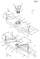
- Fig. 2 shows an exploded view of the shortened hand lever 2 and 3 together with the bearing pin 6.
- the first hand lever 2 and the second hand lever 3 is shown only in the region of the guide plate 12 and the bearing plate 13.
- the first hand lever 2 is again shown with its guide plate 12 from its underside, while the hand lever 3 is shown with its bearing plate in the same position visible from the top, as shown in Fig. 1 is recognizable.
- Fig. 2 It can be seen that the head part 26 of the journal 6 is formed radially widened. Accordingly, the bearing pin 6 "below" the head portion 26 forms a radially tapered bearing cylinder 35, to which a downwardly radially tapered trained threaded portion 36 connects downwards.
- the bearing pin 6 is with its threaded portion 36 and its bearing cylinder 35 through a bearing bore 37 of the guide plate 12 can be inserted therethrough. Since the guide plate 12 is shown from the underside, this insertion is carried out by the in Fig. 2 now "bottom” arranged upper boundary surface 29 of the guide plate 12th
- a spacer element in the form of an annular web 39 is provided, which forms a narrow support surface 40.
- the guide plate 12 is supported axially in the "open” cleaning state "upper side" on the bearing plate 13 from. This ensures that the guide plate 12 in the open cleaning position can not inadvertently come into contact with the recess 14 of the bearing plate 13 and thus both part can be acted upon for cleaning purposes with a cleaning liquid.
- the bearing plate 13 has for receiving the threaded portion 36 of the journal 6 centrally a corresponding internal thread 41, in which the bearing pin 6 is fixed screwed.
- the contour of the "recessed” arranged in the bearing plate 13 recess 14 corresponds approximately to the contour of the two stop webs 19 and 20. Accordingly, the boundary of the recess 14 in the region of the stop web 19 on a transverse portion 42 and an inclined portion 43 as a boundary edge of the recess 14.
- the stop web 20 associated limit the recess 14 has the "back" of the bearing plate 13 towards a transverse portion 44 and to the "front side" of the bearing plate 13 toward a slanted portion 45.
- the distance a of the two transverse sections 42 and 44 corresponds to at least the width b of the guide plate 12. Accordingly, the guide plate 12 in the direction of arrow 16 in a direction perpendicular to the bearing plate 13 adjusted angular position with the lying between the two sections 42 and 44 area the depression be covered.
- the two with respect to the longitudinal center axis or axis of rotation 5 mirror-symmetrically opposite inclined portions 43 and 45, extend to the passing through the axis of rotation 5 longitudinal median plane 10 at a helix angle of about 60 °. This skew angle can also assume other values.
- FIG. 3 a section III-III off Fig. 1 in the region of the guide plate 12 and the bearing plate 13. It can be seen that the guide plate 12 is received in the two receiving grooves 17 and 18 of the bearing plate 13 and rests flat with its lower contact surface 38 on the sliding surface 47 of the bearing plate 13. To prevent axial movement in the direction of the arrow 48 along the journal 6, the two upper stop webs 19 and 20 are provided, so that the guide plate 12 in the in Fig. 3 shown closed operating state, fitting in the two grooves 17 and 18 is added.
- the length of the bearing journal is designed such that the lower boundary surface 28 of the head part 26 has a small distance from the annular surface 30 formed by the depression 27. This also achieves a purge in this area, in particular in the cleaning position of the two hand lever 2 and 3 to each other, with cleaning fluid.
- a rotational movement of the first hand lever 2 in the direction of arrow 25 by at least 60 ° and at most 90 ° is required in the illustrated embodiment.
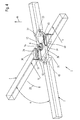
- Fig. 4 shows a perspective view of the medical instrument 1 in a cleaning position in which the first hand lever 2 is adjusted relative to the second hand lever 3 by a rotational angle ⁇ of 60 ° in the direction of the arrow 25.
- Fig. 5 shows a sectional view VV of the medical instrument 1 from Fig. 4 . It can be seen that the guide plate 12 in the in Fig. 4 shown angular position of the two hand lever 2 and 3 is no longer with the two grooves 17 and 18 is engaged. In this position, the guide plate 12 is fully circumferentially in the region of vertical in the direction of arrow 16 below the sliding surfaces 47 surface 55 of the recess 14 and has to this surface 55 a corresponding distance, which the "axial" height h of the annular web 39th equivalent.
- the annular rib 39 rests with its extremely narrow support surface 40 on the surface 55. With normal handling of the instrument 1 and the now exposed guide plate 12, this can move in the direction of the arrow 48, so that a flushing of the parts to be cleaned in the in Fig. 5 shown in section cleaning position of the guide plate 12 relative to the bearing plate 13 can be done optimally.
- the recess 27 can also be omitted if necessary, with the axial length of the journal 6 in this case too choose that the bottom 28 of the head portion 26 has an at least minimum distance from the upper boundary surface 29 of the guide plate 12 (not shown in the drawing).
- the annular web 39 used as a spacer can, on the one hand, be an integral component of the guide plate 12 but also optionally of the bearing plate 13. Further, this ring land 39 may be formed as a separate component, which is "loose" between the guide plate 12 and the bearing plate 13 is inserted.
- an angular range of 30 ° is possible as a cleaning position, so that the operator does not have to pay special attention to ensure that the guide plate 12 precisely on the recess 14th to align.
Landscapes
- Health & Medical Sciences (AREA)
- Surgery (AREA)
- Life Sciences & Earth Sciences (AREA)
- Biomedical Technology (AREA)
- Nuclear Medicine, Radiotherapy & Molecular Imaging (AREA)
- Engineering & Computer Science (AREA)
- Ophthalmology & Optometry (AREA)
- Heart & Thoracic Surgery (AREA)
- Medical Informatics (AREA)
- Molecular Biology (AREA)
- Animal Behavior & Ethology (AREA)
- General Health & Medical Sciences (AREA)
- Public Health (AREA)
- Veterinary Medicine (AREA)
- Dental Tools And Instruments Or Auxiliary Dental Instruments (AREA)
Applications Claiming Priority (1)
| Application Number | Priority Date | Filing Date | Title |
|---|---|---|---|
| DE202013010321.3U DE202013010321U1 (de) | 2013-11-14 | 2013-11-14 | Zangenartiges medizinisches Instrument |
Publications (1)
| Publication Number | Publication Date |
|---|---|
| EP2873381A1 true EP2873381A1 (fr) | 2015-05-20 |
Family
ID=50029895
Family Applications (1)
| Application Number | Title | Priority Date | Filing Date |
|---|---|---|---|
| EP20140003803 Withdrawn EP2873381A1 (fr) | 2013-11-14 | 2014-11-12 | Instrument médical de type pince |
Country Status (2)
| Country | Link |
|---|---|
| EP (1) | EP2873381A1 (fr) |
| DE (1) | DE202013010321U1 (fr) |
Cited By (5)
| Publication number | Priority date | Publication date | Assignee | Title |
|---|---|---|---|---|
| CN105215870A (zh) * | 2015-10-21 | 2016-01-06 | 和弘手术器械(上海)有限公司 | 一种镶配式医用钳 |
| WO2017216039A1 (fr) * | 2016-06-16 | 2017-12-21 | Aesculap Ag | Instrument chirurgical présentant un élément pivotant de conservation de la distance |
| WO2018166989A1 (fr) * | 2017-03-16 | 2018-09-20 | Aesculap Ag | Pince chirurgicale réalisée par fabrication additive et procédé de réalisation d'une telle pince |
| DE102017109125A1 (de) | 2017-04-27 | 2018-10-31 | Aesculap Ag | Chirurgisches Instrument der zwei Branchen-Bauart mit verbesserter Reinigungseignung |
| DE102021108716A1 (de) | 2021-04-08 | 2022-10-13 | Aesculap Ag | Schraubwerkzeug sowie Montageverfahren mit Schraubwerkzeug |
Families Citing this family (6)
| Publication number | Priority date | Publication date | Assignee | Title |
|---|---|---|---|---|
| DE102016116624A1 (de) * | 2016-09-06 | 2018-03-22 | Karl Leibinger Medizintechnik Gmbh & Co. Kg | Medizinisches Instrument mit Reinigungsspalt im Verschlussbereich |
| DE102016116623A1 (de) | 2016-09-06 | 2018-03-08 | Karl Leibinger Medizintechnik Gmbh & Co. Kg | Werkzeuglos montierbares/demontierbares medizinisches Instrument |
| DE102016116627A1 (de) | 2016-09-06 | 2018-03-08 | Karl Leibinger Medizintechnik Gmbh & Co. Kg | Einfach montierbares / demontierbares medizinisches Handwerkzeug |
| DE102019105268A1 (de) * | 2019-03-01 | 2020-09-03 | Aesculap Ag | Medizinisches Instrument und Verfahren zum Herstellen eines medizinischen Instruments |
| DE102020127497A1 (de) * | 2020-10-19 | 2022-04-21 | Aesculap Ag | Medizinisches Instrument mit gleichmäßiger Ganghärte |
| DE102021119434A1 (de) | 2021-07-27 | 2023-02-02 | Aesculap Ag | Medizinisches Instrument und Verfahren zum Herstellen eines medizinischen Instruments |
Citations (4)
| Publication number | Priority date | Publication date | Assignee | Title |
|---|---|---|---|---|
| DE20100589U1 (de) * | 2001-01-13 | 2001-05-03 | Aesculap AG & Co. KG, 78532 Tuttlingen | Chirurgisches Instrument |
| DE202010010843U1 (de) | 2010-07-29 | 2010-11-04 | Richard Martin Medizintechnik Gmbh | Medizinisches Handwerkzeug |
| US20110106065A1 (en) * | 2009-10-22 | 2011-05-05 | Thomas Tontarra | Surgical instrument |
| DE202011107977U1 (de) | 2011-11-17 | 2011-11-30 | Innovations-Medical Gmbh | Medizinisches Instrument |
-
2013
- 2013-11-14 DE DE202013010321.3U patent/DE202013010321U1/de not_active Expired - Lifetime
-
2014
- 2014-11-12 EP EP20140003803 patent/EP2873381A1/fr not_active Withdrawn
Patent Citations (4)
| Publication number | Priority date | Publication date | Assignee | Title |
|---|---|---|---|---|
| DE20100589U1 (de) * | 2001-01-13 | 2001-05-03 | Aesculap AG & Co. KG, 78532 Tuttlingen | Chirurgisches Instrument |
| US20110106065A1 (en) * | 2009-10-22 | 2011-05-05 | Thomas Tontarra | Surgical instrument |
| DE202010010843U1 (de) | 2010-07-29 | 2010-11-04 | Richard Martin Medizintechnik Gmbh | Medizinisches Handwerkzeug |
| DE202011107977U1 (de) | 2011-11-17 | 2011-11-30 | Innovations-Medical Gmbh | Medizinisches Instrument |
Cited By (15)
| Publication number | Priority date | Publication date | Assignee | Title |
|---|---|---|---|---|
| CN105215870A (zh) * | 2015-10-21 | 2016-01-06 | 和弘手术器械(上海)有限公司 | 一种镶配式医用钳 |
| US10925626B2 (en) | 2016-06-16 | 2021-02-23 | Aesculap Ag | Surgical instrument having a spacing pivoting element |
| WO2017216039A1 (fr) * | 2016-06-16 | 2017-12-21 | Aesculap Ag | Instrument chirurgical présentant un élément pivotant de conservation de la distance |
| WO2018166989A1 (fr) * | 2017-03-16 | 2018-09-20 | Aesculap Ag | Pince chirurgicale réalisée par fabrication additive et procédé de réalisation d'une telle pince |
| CN110325128B (zh) * | 2017-03-16 | 2023-03-14 | 蛇牌股份公司 | 增材制造的医疗器械以及制造这种器械的方法 |
| CN110325128A (zh) * | 2017-03-16 | 2019-10-11 | 蛇牌股份公司 | 增材制造的医疗器械以及制造这种器械的方法 |
| US11369395B2 (en) | 2017-03-16 | 2022-06-28 | Aesculap Ag | Surgical clamp produced by additive manufacturing and a method for producing such a clamp |
| DE102017109125A1 (de) | 2017-04-27 | 2018-10-31 | Aesculap Ag | Chirurgisches Instrument der zwei Branchen-Bauart mit verbesserter Reinigungseignung |
| US11369396B2 (en) | 2017-04-27 | 2022-06-28 | Aesculap Ag | Surgical instrument of two-branch design with improved cleaning suitability |
| CN110740699A (zh) * | 2017-04-27 | 2020-01-31 | 蛇牌股份公司 | 具有改进的清洁适宜性的双分支设计的外科器械 |
| WO2018197679A1 (fr) | 2017-04-27 | 2018-11-01 | Aesculap Ag | Instrument chirurgical de construction à deux branches avec facilité de nettoyage améliorée |
| CN110740699B (zh) * | 2017-04-27 | 2023-07-25 | 蛇牌股份公司 | 具有改进的清洁适宜性的双分支设计的外科器械 |
| DE102021108716A1 (de) | 2021-04-08 | 2022-10-13 | Aesculap Ag | Schraubwerkzeug sowie Montageverfahren mit Schraubwerkzeug |
| WO2022218770A1 (fr) | 2021-04-08 | 2022-10-20 | Aesculap Ag | Outil de vissage et procédé d'assemblage utilisant un outil de vissage |
| US12521135B2 (en) | 2021-04-08 | 2026-01-13 | Aesculap Ag | Screwdriving tool and assembly method using a screwdriving tool |
Also Published As
| Publication number | Publication date |
|---|---|
| DE202013010321U1 (de) | 2014-01-15 |
Similar Documents
| Publication | Publication Date | Title |
|---|---|---|
| EP2873381A1 (fr) | Instrument médical de type pince | |
| EP2594210B1 (fr) | Instrument médical | |
| EP2880334B1 (fr) | Anneau à écrou | |
| EP2412324B1 (fr) | Outil manuel médical | |
| EP0116305A1 (fr) | Pince pour tuyaux | |
| EP0528252A1 (fr) | Pince avec deux bras | |
| EP3779111A1 (fr) | Dispositif de synchronisation pour déplacer des parties d'un meuble | |
| EP3153115B1 (fr) | Kerrison rongeur avec coulisseau d'estampage imperdable | |
| EP4103357B1 (fr) | Pince | |
| DE112009001858B4 (de) | Tightening Device With Cam Lever | |
| EP2169163B1 (fr) | Charnière réglable en hauteur | |
| DE19938512A1 (de) | Miniatur-Entgratwerkzeug | |
| EP3411188B1 (fr) | Tenaille | |
| DE202012101617U1 (de) | Medizinisches Spekulum | |
| EP2915618B1 (fr) | Pince ou ciseaux | |
| EP3614937B1 (fr) | Instrument chirurgical de construction à deux branches avec facilité de nettoyage améliorée | |
| EP3153279B1 (fr) | Outil formé à la manière d'une pince d'écartement | |
| EP2946646B1 (fr) | Dispositif doté d'un dispositif d'arrêt | |
| DE102006056004B4 (de) | Gelenkbeschlag für Kraftfahrzeugsitze mit mindestens zwei Sperrarmen | |
| EP2965701B1 (fr) | Pince à tige | |
| EP1762768B1 (fr) | Dispositif écarteur ajustable | |
| DE102007033189A1 (de) | Ringzange | |
| EP1788173B1 (fr) | Dispositif de réglage latéral | |
| DE3117118A1 (de) | Scharnier, insbesondere fuer tueren, wie tueren von sicherungs- oder schaltkaesten | |
| DE102006062326A1 (de) | Stützvorrichtung für ein Scharnier einer Schließeinheit |
Legal Events
| Date | Code | Title | Description |
|---|---|---|---|
| PUAI | Public reference made under article 153(3) epc to a published international application that has entered the european phase |
Free format text: ORIGINAL CODE: 0009012 |
|
| 17P | Request for examination filed |
Effective date: 20141112 |
|
| AK | Designated contracting states |
Kind code of ref document: A1 Designated state(s): AL AT BE BG CH CY CZ DE DK EE ES FI FR GB GR HR HU IE IS IT LI LT LU LV MC MK MT NL NO PL PT RO RS SE SI SK SM TR |
|
| AX | Request for extension of the european patent |
Extension state: BA ME |
|
| STAA | Information on the status of an ep patent application or granted ep patent |
Free format text: STATUS: THE APPLICATION IS DEEMED TO BE WITHDRAWN |
|
| 18D | Application deemed to be withdrawn |
Effective date: 20151121 |