EP4105103A1 - Dispositif de détection d'environnement à ajustement automatique pour véhicules ferroviaires - Google Patents
Dispositif de détection d'environnement à ajustement automatique pour véhicules ferroviaires Download PDFInfo
- Publication number
- EP4105103A1 EP4105103A1 EP22166893.2A EP22166893A EP4105103A1 EP 4105103 A1 EP4105103 A1 EP 4105103A1 EP 22166893 A EP22166893 A EP 22166893A EP 4105103 A1 EP4105103 A1 EP 4105103A1
- Authority
- EP
- European Patent Office
- Prior art keywords
- detection unit
- rail
- unit
- detected
- environment
- Prior art date
- Legal status (The legal status is an assumption and is not a legal conclusion. Google has not performed a legal analysis and makes no representation as to the accuracy of the status listed.)
- Granted
Links
Images



Classifications
-
- B—PERFORMING OPERATIONS; TRANSPORTING
- B61—RAILWAYS
- B61L—GUIDING RAILWAY TRAFFIC; ENSURING THE SAFETY OF RAILWAY TRAFFIC
- B61L23/00—Control, warning or like safety means along the route or between vehicles or trains
- B61L23/04—Control, warning or like safety means along the route or between vehicles or trains for monitoring the mechanical state of the route
- B61L23/041—Obstacle detection
-
- B—PERFORMING OPERATIONS; TRANSPORTING
- B61—RAILWAYS
- B61L—GUIDING RAILWAY TRAFFIC; ENSURING THE SAFETY OF RAILWAY TRAFFIC
- B61L15/00—Indicators provided on the vehicle or train for signalling purposes
- B61L15/0072—On-board train data handling
-
- B—PERFORMING OPERATIONS; TRANSPORTING
- B61—RAILWAYS
- B61L—GUIDING RAILWAY TRAFFIC; ENSURING THE SAFETY OF RAILWAY TRAFFIC
- B61L25/00—Recording or indicating positions or identities of vehicles or trains or setting of track apparatus
- B61L25/02—Indicating or recording positions or identities of vehicles or trains
- B61L25/021—Measuring and recording of train speed
Definitions
- the invention relates to an environment detection device.
- the invention also relates to a surroundings detection method.
- the invention also relates to a rail vehicle.
- sensor devices Due to the long braking distances in rail traffic, sensor devices are required for assisted driving or even autonomous driving of rail vehicles, with which an area far away from the rail vehicle, particularly in the vicinity of the rail route traveled by the rail vehicle, can be monitored.
- the sensors used hitherto have generally only had a low resolution, so that it has hitherto not been possible to classify or identify different objects over large distances.
- Part of the surroundings detection device according to the invention is also a surroundings detection unit, which is arranged or aligned in a fixed orientation relationship to the rail section detection unit and is set up to record the surroundings of the rail vehicle, which are also preferably located in the front area in front of the rail vehicle, and the course of the rails or the rail section, which may be part of the Environment is to capture.
- a fixed orientation relationship should be understood to mean that the relative orientation of the rail section detection unit and the environment detection unit are always constant.
- the surroundings detection device comprises a bearing or bearing unit common to the rail section detection unit and the surroundings detection unit.
- the surroundings detection device includes a control unit.
- the storage unit is set up to store the rail section detection unit and the environment detection unit in an orientation-stable manner.
- Orientation-stable mounting should be understood in this context to mean that a preferably common orientation of the rail section detection unit and the environment detection unit set by the control unit is maintained by the mounting, even if the rail vehicle changes its orientation.
- the bearing must therefore allow a rotary movement or pivoting movement of the rail vehicle relative to the rail section detection unit and the environment detection unit, without this movement of the rail vehicle being transmitted to the rail section detection unit and the environment detection unit.
- the control unit is designed to align the orientation of the environment detection unit with the detected position and the course of the railway line detected by the railway line detection unit, so that the region of the railway line and the environment of the railway line can be captured by the environment detection unit.
- self-adjusting monitoring of a rail section preferably located in front of a rail vehicle takes place in that the rail section is detected and localized by the rail section detection unit and this, together with the environment detection unit, is aligned with a section of the rail line to be monitored.
- the actual monitoring and identification of objects in the observation area is then carried out on the basis of data from the surroundings detection unit. If the course of the rail line changes, this change is detected by the rail line detection unit and the environment detection unit is precisely aligned with the rail line detection unit by the control unit to the observation area around the rail line or tracked accordingly. Due to the automated tracking, the extent of the field of view of the surroundings detection unit can be reduced by one to two orders of magnitude compared to a sensor unit without such tracking. This reduction is associated with an improvement in the sharpness of direction, the resolution and the range of the environment detection unit.
- a position and a course of a rail section in the vicinity of a rail vehicle are detected by a rail section detection unit.
- the environment of the rail vehicle is detected by an environment detection unit, which is arranged in a fixed orientation relationship to the track detection unit.
- the rail section detection unit and the environment detection unit are mounted in a common mounting unit in a stable orientation.
- the orientation of the environment detection unit is adjusted by a control unit to the detected course of the rail line, so that the area of the rail line and the environment of the rail line can be detected by the environment detection unit.
- the surroundings detection method according to the invention shares the advantages of the surroundings detection device according to the invention.
- the rail vehicle according to the invention has the surroundings detection device according to the invention.
- the rail vehicle according to the invention shares the advantages of the surroundings detection device according to the invention.
- Some components of the surroundings detection device according to the invention can, if necessary after the addition of hardware systems, such as a sensor unit and mechanical components of a storage unit, for the most part be designed in the form of software components. This applies in particular to parts of the control unit and the storage unit.
- these components can also be partially implemented in the form of software-supported hardware, for example FPGAs or the like, particularly when particularly fast calculations are involved.
- the required interfaces for example when it is only a matter of taking over data from other software components, can be designed as software interfaces. However, they can also be in the form of hardware interfaces that are controlled by suitable software.
- a largely software-based implementation has the advantage that even previously existing in a rail vehicle computer systems after a possible supplement by additional Hardware elements, such as additional sensor units, can be retrofitted in a simple manner by means of a software update in order to work in the manner according to the invention.
- the object is also achieved by a corresponding computer program product with a computer program, which can be loaded directly into a memory device of such a computer system, with program sections to execute the steps of the method according to the invention that can be implemented by software when the computer program is executed in the computer system.
- such a computer program product may also include additional components such as documentation and/or additional components, including hardware components such as hardware keys (dongles, etc.) for using the software
- a computer-readable medium for example a memory stick, a hard disk or another transportable or permanently installed data medium, on which the program sections of the computer program that can be read and executed by a computer unit are stored, can be used for transport to the storage device of the computer system and/or for storage on the computer system.
- the computer unit can, for example, have one or more microprocessors or the like working together.
- the storage unit includes a gimbal.
- a gimbal is to be understood as a motorized storage unit that can make movements of a sensor unit smoother or stabilize an observation or recording area.
- the rail section detection unit and the surroundings detection unit are then arranged in a fixed orientation relationship on the gimbal.
- the two sensor units only have to be calibrated once in advance with respect to their orientation, since they both have a fixed orientation relationship to one another, which can no longer change during operation.
- Such a gimbal can include command data as input variables for controlling an orientation generated or determined or to be set on the basis of the sensor data of the rail section detection unit.
- input variables can also include movements of the rail vehicle, a so-called sine run, as well as deviations in height as a result of unevenness in the track and a current incline.
- the sensors of the surroundings detection device can be tracked more precisely and without interference.
- Such a bearing unit can, in particular, comprise a cardanic suspension, which prevents an unwanted change in direction of the sensor system due to external mechanical influences.
- the measurement accuracy of both the track section detection unit and the environment detection unit can advantageously be increased.
- Using a gimbal can reduce field-of-view drift from passive sensors, such as optical sensors or infrared sensors. This allows longer "exposure times" to be implemented, which improves the sensitivity of the passive sensors.
- inertial measuring units acceleration sensor systems or magnetic field sensor systems can be used to measure orientation and stabilization of the orientation of the sensors of the surroundings detection device.
- the rail section detection unit comprises a passive detection unit.
- a passive detection unit for example a passive sensor unit, can advantageously be designed with an extended field of view.
- the rail section detection unit can use, for example, preferably passive infrared image detection or lidar sensor technology as the recording technology. It can also include an optical detection unit.
- a passive infrared sensor unit has high accuracy in target acquisition. However, the infrared sensor unit requires temperature differences. Lidar enables three-dimensional scanning of objects, but is less precise than passive sensors, especially infrared sensors, due to the pixel-by-pixel scanning of the environment.
- Radar is particularly well suited for capturing a high-precision radar map or resolved details in order to classify or identify a detected object.
- the radar data can be used as a complement to passively recorded data, for example optical data or infrared data, in order to expand the data basis for object recognition.
- Radar has a very good depth resolution, especially in comparison to passive sensor methods. With radar, the lateral resolution of a passive infrared camera can be improved in a complementary way.
- Lidar has improved resolution compared to radar.
- Stereo cameras also have the advantage of good depth resolution and combine this advantage with generally increased resolution compared to active scanning systems.
- the rail section detection unit and the environment detection unit of the environment detection device are particularly preferably set up to acquire mutually complementary data that allow comprehensive information about objects in the environment of a rail vehicle to be ascertained.
- the relative speed between a detected object and the rail vehicle can be determined, for example, by an exact measurement of a radial and a lateral Doppler component of the sensor waves, preferably radar waves, reflected by a detected object.
- a radial and a lateral Doppler component of the sensor waves preferably radar waves
- slow movements can also be measured.
- the corresponding speed values can be used for classification and identification of a detected object.
- the orientation-stable measuring apparatus determine the exact angle of the direction of movement of a detected object to the ego speed of the rail vehicle and thus determine a relevance of an object with regard to a collision event more reliably.
- Knowledge of highly accurate speed information can also be used to support or improve accuracy when determining the ego position of a rail vehicle.
- the variables mentioned can be used advantageously for an exact determination of an orientation of the sensor system of the rail vehicle and possibly also for an improvement of digital map material with regard to the rail section traveled or a rail section present in the vicinity of the rail vehicle.
- This data can be used for a more precise alignment of the overall system made up of environment detection unit and distance detection unit, in order to carry out particularly precise position determinations of detected objects.
- the invention also allows the generation of high-precision relative route maps by using active sensor technologies such as radar, with the data recorded by these sensors being related to the data from the complementary passive sensors, for example to a track center line recorded by the passive sensors. Based on these relative route maps, absolute map data with geo-coordinates can also be obtained.
- the control unit of the surroundings detection device is preferably designed to adjust the orientation of the surroundings detection unit in such a way that an active limitation of the detected surroundings is achieved.
- an active limitation of the detected surroundings is achieved.
- people or technical equipment present in the periphery can be prevented from being adversely affected by active sensors, such as radar waves, for example.
- active sensors such as radar waves, for example.
- a higher radiated power can be achieved, in particular with regard to simplified radio approval or as a basis for arguments with regulatory bodies in order to have higher transmission powers approved.
- the control unit of the surroundings detection device can be designed to align the orientation of the surroundings detection unit beyond a detection range of the rail section detection unit.
- the course of the route is extrapolated beyond the recorded track based on the recorded track and map data. Consequently, the surroundings detection unit can be aligned to a track position in the situational visibility range of the surroundings detection unit beyond the situational visibility range of the track for the rail section detection unit.
- the environment detection unit can advantageously also be aligned to an area that is outside the range of the distance detection unit.
- the environment detection unit can also have an electronic beam steering function, in particular if it comprises a radar sensor unit.
- the environment detection unit has a plurality of individual channels.
- the Beam steering can be done by choosing the phase relationships of the channels.
- a reception direction can be calculated via the phase relationships of the reception signals.
- FIG 1 a schematic representation 10 of a rail vehicle 2 with a surroundings detection device 3 according to an exemplary embodiment of the invention is illustrated.
- the rail vehicle 2 is located on a rail track 1 and uses the environment detection device 3 mentioned to capture an observation area B which is arranged in front of the rail vehicle 2 on the rail track 1 and around the rail track 1 .
- the environment detection device 3 has a passive infrared sensor unit 6 as a track detection unit.
- the environment detection device 3 is designed to be pivotable about three axes relative to the rail vehicle 2 so that it can follow the curves of the rail line 1 . So that a set direction of the sensor system can be maintained, the environment detection device 3 has a gimbal 4 on which the sensor system 5, 6 is mounted.
- a radar sensor unit 5 is also arranged on the gimbal 4 as an environment detection unit. The radar sensor unit 5 is calibrated beforehand in such a way that it targets the same observation area B as the passive infrared sensor unit 6.
- the passive infrared unit 6 has an extended recording area and is therefore well suited for searching for a desired observation area B.
- the observation area B been identified and suitably centered for the passive infrared sensor unit 6 as shown in FIG 1 is illustrated, the radar sensor unit 5 embodied as a surroundings detection unit is also automatically directed towards this observation area B. In this way, the limitation of the field of view of the radar sensor unit 5 is compensated for by the wide field of view of the passive infrared unit 6 .
- the radar sensor unit 5 advantageously has a high lateral resolution and a long range, so that the details of objects O in the observation area B can be detected.
- the rail vehicle 2 has a control unit 7 .
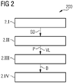
- step 2.I infrared sensor data SD from a frontal monitoring area in front of a rail vehicle 2 is detected by an infrared sensor unit 5 used as a track detection unit.
- the infrared sensor unit 5 is mounted in an orientation-stable manner on a gimbal 4 together with a radar sensor unit 6 embodied as a surroundings detection unit.
- step 2.II a position P and a course VL of the rail section in front of the rail vehicle 2 are detected on the basis of the infrared sensor data SD.
- an observation area B in front of the rail vehicle 2 is also determined, which includes the rail section and possibly an edge area around it.
- step 2.III the gimbal 4 is aligned by a control unit 7 in such a way that the field of view of the infrared sensor unit 5 is centered on the observation area B.
- the radar sensor unit 6 previously calibrated to the infrared sensor unit 5 is also directed to the observation area B.
- step 2.IV radar sensor data can then be recorded from the observation area B with increased lateral resolution and depth resolution as well as a large range.
- FIG. 3 a schematic representation 30 of a detection of complementary data by a radar 5 and a passive infrared camera 6 of a surroundings detection device 3 according to an exemplary embodiment of the invention is illustrated.
- the left-hand section of the image shows a rail section 1 on which a rail vehicle 2 with the environment detection device 3 mentioned is located.
- the environment detection device 3 now acquires complementary data d, v, M, h 1 , h 2 via its two different sensor units 5, 6.
- the radar sensor unit 5 of the rail vehicle 2 in the observation area B for example, acquires an object O and its relative speed v and distance d to the radar sensor unit 5 of the rail vehicle 2.
- the infrared sensor unit 6, complementary to the radar sensor unit 5, detects the lateral structure and the height of the track body GB.
- the height h 1 , h 2 of the rails 1a and the dimensions of the sleepers 1b and the course of the track or the course of the center line M of the tracks are recorded.
- three different views of a track body GB are shown.
- a cross section of the track body GB is shown in an upper partial representation. Detected dimensions can relate, for example, to the rail heights h 1 , h 2 of the rails 1a, but also to the dimensions and positions of the sleepers 1b.
- a top view of the track body GB is shown in a central partial representation in the right-hand section of the figure.
- the center line M of the course of the track is illustrated in particular, which can also be detected by the infrared sensor unit 6 .
- a side view of a track body GB is shown in 3 .
- the path-dependent height profile h 1 (s) of a rail 1a can be seen, which can also be detected by the infrared sensor unit 6 .
- FIG 4 a schematic plan view 40 is shown of a rail section 1, on which a rail vehicle 2 with a surroundings detection device 3 according to an exemplary embodiment of the invention is illustrated.
- the rail vehicle 2 has a relative speed v with a radial component v r and a lateral component v l relative to a detected object O.
- the gimbal of the environment detection device 3 is not aligned in the direction of travel, but at an angle ⁇ to it.
- the angle ⁇ changes due to the lateral and radial movement of the rail vehicle 2.
- the images of the object O taken from different directions by the radar sensor unit 5 can be combined with one another by using a SAR algorithm in order to achieve improved resolution and an enlarged effective field of view of the radar 5.
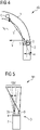
- FIG. 5 shows a top view 50 of a rail vehicle 2 with a surroundings detection device 3 according to an exemplary embodiment of the invention with a radar sensor unit 5a with electronic beam deflection.
- the radar sensor unit 5a swivels its radar beam in different directions, so that an enlarged field of view with an increased resolution can be achieved.
- the radar beam can be swiveled both in the elevation direction and in the azimuth direction.
- a top view is shown which illustrates an extension of the range of a surroundings detection device 3 of a rail vehicle 1 according to an exemplary embodiment of the invention beyond the range of a passive infrared sensor unit 6 used as a rail section detection unit.
- the range of the infrared sensor unit 6 is not sufficient to capture the desired observation area B around the object O.
- map data K which is shown in 6 are shown in a right partial representation, added.
- the position of the observation area B can be determined on the basis of the infrared measurement and the map data K and the gimbal 4 of the environment detection device 3 can now be aligned in such a way that the desired observation area B is in the field of view of the radar beam of the radar sensor unit 5.
Landscapes
- Engineering & Computer Science (AREA)
- Mechanical Engineering (AREA)
- Optical Radar Systems And Details Thereof (AREA)
Applications Claiming Priority (1)
| Application Number | Priority Date | Filing Date | Title |
|---|---|---|---|
| DE102021206083.8A DE102021206083A1 (de) | 2021-06-15 | 2021-06-15 | Selbstjustierende Umfelderfassungseinrichtung für Schienenfahrzeuge |
Publications (2)
| Publication Number | Publication Date |
|---|---|
| EP4105103A1 true EP4105103A1 (fr) | 2022-12-21 |
| EP4105103B1 EP4105103B1 (fr) | 2025-02-12 |
Family
ID=81325895
Family Applications (1)
| Application Number | Title | Priority Date | Filing Date |
|---|---|---|---|
| EP22166893.2A Active EP4105103B1 (fr) | 2021-06-15 | 2022-04-06 | Dispositif de détection d'environnement à ajustement automatique pour véhicules ferroviaires et procédé correspondant |
Country Status (3)
| Country | Link |
|---|---|
| EP (1) | EP4105103B1 (fr) |
| DE (1) | DE102021206083A1 (fr) |
| ES (1) | ES3027382T3 (fr) |
Families Citing this family (1)
| Publication number | Priority date | Publication date | Assignee | Title |
|---|---|---|---|---|
| DE102023208728A1 (de) | 2023-09-08 | 2025-03-13 | Robert Bosch Gesellschaft mit beschränkter Haftung | Verfahren und Vorrichtung zur Kollisionsüberwachung für ein Schienenfahrzeug |
Citations (3)
| Publication number | Priority date | Publication date | Assignee | Title |
|---|---|---|---|---|
| WO2004028881A1 (fr) * | 2002-09-23 | 2004-04-08 | Siemens Aktiengesellschaft | Systeme de capteurs et procede de surveillance de la voie de circulation d'une unite mobile |
| DE19746970B4 (de) * | 1997-10-24 | 2017-03-16 | Alcatel Lucent | Verfahren zur Erkennung von Hindernissen vor Schienenfahrzeugen |
| EP3521132A1 (fr) * | 2018-02-01 | 2019-08-07 | KNORR-BREMSE Systeme für Schienenfahrzeuge GmbH | Procédé de détection d'un couloir de circulation des véhicules ferroviaires |
Family Cites Families (2)
| Publication number | Priority date | Publication date | Assignee | Title |
|---|---|---|---|---|
| DE102004050690A1 (de) | 2004-10-18 | 2006-04-20 | Siemens Ag | Verfahren, Computer-Programm mit Programm-Code-Mitteln, Computer-Programm-Produkt und Gerät zur Modellierung der Umwelt eines autonomen mobilen Systems |
| CN112351928B (zh) | 2018-07-10 | 2023-11-10 | 铁路视像有限公司 | 基于轨道分段的铁路障碍物检测的方法与系统 |
-
2021
- 2021-06-15 DE DE102021206083.8A patent/DE102021206083A1/de not_active Withdrawn
-
2022
- 2022-04-06 ES ES22166893T patent/ES3027382T3/es active Active
- 2022-04-06 EP EP22166893.2A patent/EP4105103B1/fr active Active
Patent Citations (3)
| Publication number | Priority date | Publication date | Assignee | Title |
|---|---|---|---|---|
| DE19746970B4 (de) * | 1997-10-24 | 2017-03-16 | Alcatel Lucent | Verfahren zur Erkennung von Hindernissen vor Schienenfahrzeugen |
| WO2004028881A1 (fr) * | 2002-09-23 | 2004-04-08 | Siemens Aktiengesellschaft | Systeme de capteurs et procede de surveillance de la voie de circulation d'une unite mobile |
| EP3521132A1 (fr) * | 2018-02-01 | 2019-08-07 | KNORR-BREMSE Systeme für Schienenfahrzeuge GmbH | Procédé de détection d'un couloir de circulation des véhicules ferroviaires |
Also Published As
| Publication number | Publication date |
|---|---|
| DE102021206083A1 (de) | 2022-12-15 |
| ES3027382T3 (en) | 2025-06-13 |
| EP4105103B1 (fr) | 2025-02-12 |
Similar Documents
| Publication | Publication Date | Title |
|---|---|---|
| EP3746346B1 (fr) | Véhicule ferroviaire et procédé de mesure d'une voie ferrée | |
| EP3584663B1 (fr) | Procédé de guidage transversal automatique d'un véhicule suiveur dans un peloton de véhicules | |
| EP1067399B1 (fr) | Procédé de détermination de la visibilité | |
| EP3523177B1 (fr) | Procédé, dispositif et véhicule sur voie, notamment véhicule ferroviaire, pour la détection d'obstacle dans le transport sur voie, en particulier le transport ferroviaire | |
| DE69635569T2 (de) | Vorrichtung zum Bestimmen der lokalen Position eines Autos auf einer Strasse | |
| DE102016224212A1 (de) | Automatisierte Freiraumerkennung mittels Differenzanalyse für Fahrzeuge | |
| DE102017222017A1 (de) | Verfahren und System zum Ermitteln und Bereitstellen eines Bodenprofils | |
| DE102016216070A1 (de) | Steuergerät, System mit solch einem Steuergerät und Verfahren zum Betrieb solch eines Systems | |
| WO2020126338A1 (fr) | Procédé et système servant à déterminer une trajectoire corrigée d'un véhicule | |
| DE102021204372A1 (de) | Orientierungsbasierte Positionsermittlung von Schienenfahrzeugen | |
| EP4029758A1 (fr) | Surveillance embarquée à sécurité critique de l'environnement d'un véhicule ferroviaire | |
| DE102022203264A1 (de) | Verfahren zum Erstellen von Kartendaten | |
| EP4105103B1 (fr) | Dispositif de détection d'environnement à ajustement automatique pour véhicules ferroviaires et procédé correspondant | |
| DE102017214022A1 (de) | Verfahren zur Ermittlung von die Eigenbewegung eines Kraftfahrzeugs beschreibenden Egodaten und Kraftfahrzeug | |
| DE102009013768A1 (de) | Verfahren und Einrichtung zum Ermitteln von Aspektwinkeln | |
| EP2995971A1 (fr) | Procede et systeme de determination de la position | |
| WO2018059735A1 (fr) | Procédé d'autolocalisation d'un véhicule | |
| EP3358372A2 (fr) | Procédé de navigation d'un véhicule | |
| EP3996967B1 (fr) | Reconnaissance des rails par lidar | |
| DE102018213994A1 (de) | Verfahren und System zur Bestimmung der Bewegung eines Kraftfahrzeuges | |
| DE102023203319A1 (de) | Spurgebundene Hinderniserkennung | |
| DE102024202974A1 (de) | Verfahren und spurgeführtes Fahrzeug zur Positionsbestimmung des spurgeführten Fahrzeugs | |
| WO2026041283A1 (fr) | Carte géographique d'un système de voies ferrées comprenant des données de paramètre de capteur | |
| DE102021101133A1 (de) | Detektion eines lateralen Endes einer Fahrbahn | |
| DE102024203289A1 (de) | Verfahren und Einrichtungen zum Betreiben eines Schienenfahrzeugs |
Legal Events
| Date | Code | Title | Description |
|---|---|---|---|
| PUAI | Public reference made under article 153(3) epc to a published international application that has entered the european phase |
Free format text: ORIGINAL CODE: 0009012 |
|
| STAA | Information on the status of an ep patent application or granted ep patent |
Free format text: STATUS: THE APPLICATION HAS BEEN PUBLISHED |
|
| AK | Designated contracting states |
Kind code of ref document: A1 Designated state(s): AL AT BE BG CH CY CZ DE DK EE ES FI FR GB GR HR HU IE IS IT LI LT LU LV MC MK MT NL NO PL PT RO RS SE SI SK SM TR |
|
| STAA | Information on the status of an ep patent application or granted ep patent |
Free format text: STATUS: REQUEST FOR EXAMINATION WAS MADE |
|
| 17P | Request for examination filed |
Effective date: 20230620 |
|
| RBV | Designated contracting states (corrected) |
Designated state(s): AL AT BE BG CH CY CZ DE DK EE ES FI FR GB GR HR HU IE IS IT LI LT LU LV MC MK MT NL NO PL PT RO RS SE SI SK SM TR |
|
| GRAP | Despatch of communication of intention to grant a patent |
Free format text: ORIGINAL CODE: EPIDOSNIGR1 |
|
| STAA | Information on the status of an ep patent application or granted ep patent |
Free format text: STATUS: GRANT OF PATENT IS INTENDED |
|
| RIC1 | Information provided on ipc code assigned before grant |
Ipc: B61L 15/00 20060101ALN20241008BHEP Ipc: B61L 25/02 20060101ALN20241008BHEP Ipc: B61L 23/04 20060101AFI20241008BHEP |
|
| INTG | Intention to grant announced |
Effective date: 20241021 |
|
| GRAS | Grant fee paid |
Free format text: ORIGINAL CODE: EPIDOSNIGR3 |
|
| GRAA | (expected) grant |
Free format text: ORIGINAL CODE: 0009210 |
|
| STAA | Information on the status of an ep patent application or granted ep patent |
Free format text: STATUS: THE PATENT HAS BEEN GRANTED |
|
| AK | Designated contracting states |
Kind code of ref document: B1 Designated state(s): AL AT BE BG CH CY CZ DE DK EE ES FI FR GB GR HR HU IE IS IT LI LT LU LV MC MK MT NL NO PL PT RO RS SE SI SK SM TR |
|
| REG | Reference to a national code |
Ref country code: GB Ref legal event code: FG4D Free format text: NOT ENGLISH |
|
| REG | Reference to a national code |
Ref country code: CH Ref legal event code: EP |
|
| REG | Reference to a national code |
Ref country code: DE Ref legal event code: R096 Ref document number: 502022002843 Country of ref document: DE |
|
| REG | Reference to a national code |
Ref country code: IE Ref legal event code: FG4D Free format text: LANGUAGE OF EP DOCUMENT: GERMAN |
|
| REG | Reference to a national code |
Ref country code: ES Ref legal event code: FG2A Ref document number: 3027382 Country of ref document: ES Kind code of ref document: T3 Effective date: 20250613 |
|
| REG | Reference to a national code |
Ref country code: NL Ref legal event code: MP Effective date: 20250212 |
|
| PG25 | Lapsed in a contracting state [announced via postgrant information from national office to epo] |
Ref country code: RS Free format text: LAPSE BECAUSE OF FAILURE TO SUBMIT A TRANSLATION OF THE DESCRIPTION OR TO PAY THE FEE WITHIN THE PRESCRIBED TIME-LIMIT Effective date: 20250512 |
|
| PG25 | Lapsed in a contracting state [announced via postgrant information from national office to epo] |
Ref country code: FI Free format text: LAPSE BECAUSE OF FAILURE TO SUBMIT A TRANSLATION OF THE DESCRIPTION OR TO PAY THE FEE WITHIN THE PRESCRIBED TIME-LIMIT Effective date: 20250212 |
|
| PG25 | Lapsed in a contracting state [announced via postgrant information from national office to epo] |
Ref country code: PL Free format text: LAPSE BECAUSE OF FAILURE TO SUBMIT A TRANSLATION OF THE DESCRIPTION OR TO PAY THE FEE WITHIN THE PRESCRIBED TIME-LIMIT Effective date: 20250212 |
|
| PGFP | Annual fee paid to national office [announced via postgrant information from national office to epo] |
Ref country code: DE Payment date: 20250620 Year of fee payment: 4 |
|
| REG | Reference to a national code |
Ref country code: LT Ref legal event code: MG9D |
|
| PG25 | Lapsed in a contracting state [announced via postgrant information from national office to epo] |
Ref country code: IS Free format text: LAPSE BECAUSE OF FAILURE TO SUBMIT A TRANSLATION OF THE DESCRIPTION OR TO PAY THE FEE WITHIN THE PRESCRIBED TIME-LIMIT Effective date: 20250612 Ref country code: NO Free format text: LAPSE BECAUSE OF FAILURE TO SUBMIT A TRANSLATION OF THE DESCRIPTION OR TO PAY THE FEE WITHIN THE PRESCRIBED TIME-LIMIT Effective date: 20250512 |
|
| PG25 | Lapsed in a contracting state [announced via postgrant information from national office to epo] |
Ref country code: NL Free format text: LAPSE BECAUSE OF FAILURE TO SUBMIT A TRANSLATION OF THE DESCRIPTION OR TO PAY THE FEE WITHIN THE PRESCRIBED TIME-LIMIT Effective date: 20250212 |
|
| PG25 | Lapsed in a contracting state [announced via postgrant information from national office to epo] |
Ref country code: HR Free format text: LAPSE BECAUSE OF FAILURE TO SUBMIT A TRANSLATION OF THE DESCRIPTION OR TO PAY THE FEE WITHIN THE PRESCRIBED TIME-LIMIT Effective date: 20250212 |
|
| PG25 | Lapsed in a contracting state [announced via postgrant information from national office to epo] |
Ref country code: PT Free format text: LAPSE BECAUSE OF FAILURE TO SUBMIT A TRANSLATION OF THE DESCRIPTION OR TO PAY THE FEE WITHIN THE PRESCRIBED TIME-LIMIT Effective date: 20250612 Ref country code: LV Free format text: LAPSE BECAUSE OF FAILURE TO SUBMIT A TRANSLATION OF THE DESCRIPTION OR TO PAY THE FEE WITHIN THE PRESCRIBED TIME-LIMIT Effective date: 20250212 |
|
| PGFP | Annual fee paid to national office [announced via postgrant information from national office to epo] |
Ref country code: FR Payment date: 20250411 Year of fee payment: 4 |
|
| PG25 | Lapsed in a contracting state [announced via postgrant information from national office to epo] |
Ref country code: GR Free format text: LAPSE BECAUSE OF FAILURE TO SUBMIT A TRANSLATION OF THE DESCRIPTION OR TO PAY THE FEE WITHIN THE PRESCRIBED TIME-LIMIT Effective date: 20250513 Ref country code: BG Free format text: LAPSE BECAUSE OF FAILURE TO SUBMIT A TRANSLATION OF THE DESCRIPTION OR TO PAY THE FEE WITHIN THE PRESCRIBED TIME-LIMIT Effective date: 20250212 |
|
| PGFP | Annual fee paid to national office [announced via postgrant information from national office to epo] |
Ref country code: AT Payment date: 20250721 Year of fee payment: 4 |
|
| REG | Reference to a national code |
Ref country code: DE Ref legal event code: R081 Ref document number: 502022002843 Country of ref document: DE Owner name: SIEMENS MOBILITY GMBH, DE Free format text: FORMER OWNER: SIEMENS MOBILITY GMBH, 81739 MUENCHEN, DE |
|
| PG25 | Lapsed in a contracting state [announced via postgrant information from national office to epo] |
Ref country code: SE Free format text: LAPSE BECAUSE OF FAILURE TO SUBMIT A TRANSLATION OF THE DESCRIPTION OR TO PAY THE FEE WITHIN THE PRESCRIBED TIME-LIMIT Effective date: 20250212 |
|
| PG25 | Lapsed in a contracting state [announced via postgrant information from national office to epo] |
Ref country code: SM Free format text: LAPSE BECAUSE OF FAILURE TO SUBMIT A TRANSLATION OF THE DESCRIPTION OR TO PAY THE FEE WITHIN THE PRESCRIBED TIME-LIMIT Effective date: 20250212 |
|
| RAP4 | Party data changed (patent owner data changed or rights of a patent transferred) |
Owner name: SIEMENS MOBILITY GMBH |
|
| PGFP | Annual fee paid to national office [announced via postgrant information from national office to epo] |
Ref country code: ES Payment date: 20250721 Year of fee payment: 4 |
|
| PG25 | Lapsed in a contracting state [announced via postgrant information from national office to epo] |
Ref country code: DK Free format text: LAPSE BECAUSE OF FAILURE TO SUBMIT A TRANSLATION OF THE DESCRIPTION OR TO PAY THE FEE WITHIN THE PRESCRIBED TIME-LIMIT Effective date: 20250212 |
|
| PG25 | Lapsed in a contracting state [announced via postgrant information from national office to epo] |
Ref country code: IT Free format text: LAPSE BECAUSE OF FAILURE TO SUBMIT A TRANSLATION OF THE DESCRIPTION OR TO PAY THE FEE WITHIN THE PRESCRIBED TIME-LIMIT Effective date: 20250212 |
|
| PGFP | Annual fee paid to national office [announced via postgrant information from national office to epo] |
Ref country code: CH Payment date: 20250709 Year of fee payment: 4 |
|
| PG25 | Lapsed in a contracting state [announced via postgrant information from national office to epo] |
Ref country code: EE Free format text: LAPSE BECAUSE OF FAILURE TO SUBMIT A TRANSLATION OF THE DESCRIPTION OR TO PAY THE FEE WITHIN THE PRESCRIBED TIME-LIMIT Effective date: 20250212 Ref country code: CZ Free format text: LAPSE BECAUSE OF FAILURE TO SUBMIT A TRANSLATION OF THE DESCRIPTION OR TO PAY THE FEE WITHIN THE PRESCRIBED TIME-LIMIT Effective date: 20250212 |
|
| PG25 | Lapsed in a contracting state [announced via postgrant information from national office to epo] |
Ref country code: RO Free format text: LAPSE BECAUSE OF FAILURE TO SUBMIT A TRANSLATION OF THE DESCRIPTION OR TO PAY THE FEE WITHIN THE PRESCRIBED TIME-LIMIT Effective date: 20250212 |
|
| PG25 | Lapsed in a contracting state [announced via postgrant information from national office to epo] |
Ref country code: SK Free format text: LAPSE BECAUSE OF FAILURE TO SUBMIT A TRANSLATION OF THE DESCRIPTION OR TO PAY THE FEE WITHIN THE PRESCRIBED TIME-LIMIT Effective date: 20250212 |
|
| REG | Reference to a national code |
Ref country code: DE Ref legal event code: R097 Ref document number: 502022002843 Country of ref document: DE |
|
| PG25 | Lapsed in a contracting state [announced via postgrant information from national office to epo] |
Ref country code: LU Free format text: LAPSE BECAUSE OF NON-PAYMENT OF DUE FEES Effective date: 20250406 |
|
| PLBE | No opposition filed within time limit |
Free format text: ORIGINAL CODE: 0009261 |
|
| STAA | Information on the status of an ep patent application or granted ep patent |
Free format text: STATUS: NO OPPOSITION FILED WITHIN TIME LIMIT |
|
| PG25 | Lapsed in a contracting state [announced via postgrant information from national office to epo] |
Ref country code: MC Free format text: LAPSE BECAUSE OF FAILURE TO SUBMIT A TRANSLATION OF THE DESCRIPTION OR TO PAY THE FEE WITHIN THE PRESCRIBED TIME-LIMIT Effective date: 20250212 |
|
| REG | Reference to a national code |
Ref country code: BE Ref legal event code: MM Effective date: 20250430 |
|
| PG25 | Lapsed in a contracting state [announced via postgrant information from national office to epo] |
Ref country code: BE Free format text: LAPSE BECAUSE OF NON-PAYMENT OF DUE FEES Effective date: 20250430 |
|
| 26N | No opposition filed |
Effective date: 20251113 |
|
| PG25 | Lapsed in a contracting state [announced via postgrant information from national office to epo] |
Ref country code: IE Free format text: LAPSE BECAUSE OF NON-PAYMENT OF DUE FEES Effective date: 20250406 |