EP4105109A1 - Unité de garde-boue pour véhicules à moteur - Google Patents
Unité de garde-boue pour véhicules à moteur Download PDFInfo
- Publication number
- EP4105109A1 EP4105109A1 EP22173993.1A EP22173993A EP4105109A1 EP 4105109 A1 EP4105109 A1 EP 4105109A1 EP 22173993 A EP22173993 A EP 22173993A EP 4105109 A1 EP4105109 A1 EP 4105109A1
- Authority
- EP
- European Patent Office
- Prior art keywords
- mudguard
- bolt
- support rod
- unit
- proximal end
- Prior art date
- Legal status (The legal status is an assumption and is not a legal conclusion. Google has not performed a legal analysis and makes no representation as to the accuracy of the status listed.)
- Granted
Links
Images



Classifications
-
- B—PERFORMING OPERATIONS; TRANSPORTING
- B62—LAND VEHICLES FOR TRAVELLING OTHERWISE THAN ON RAILS
- B62D—MOTOR VEHICLES; TRAILERS
- B62D25/00—Superstructure or monocoque structure sub-units; Parts or details thereof not otherwise provided for
- B62D25/08—Front or rear portions
- B62D25/16—Mud-guards or wings; Wheel cover panels
- B62D25/163—Mounting devices
- B62D25/166—Mounting devices by rods or other distance-keeping devices
-
- B—PERFORMING OPERATIONS; TRANSPORTING
- B62—LAND VEHICLES FOR TRAVELLING OTHERWISE THAN ON RAILS
- B62D—MOTOR VEHICLES; TRAILERS
- B62D25/00—Superstructure or monocoque structure sub-units; Parts or details thereof not otherwise provided for
- B62D25/08—Front or rear portions
- B62D25/16—Mud-guards or wings; Wheel cover panels
- B62D25/161—Mud-guards made of non-conventional material, e.g. rubber, plastics
-
- B—PERFORMING OPERATIONS; TRANSPORTING
- B62—LAND VEHICLES FOR TRAVELLING OTHERWISE THAN ON RAILS
- B62D—MOTOR VEHICLES; TRAILERS
- B62D25/00—Superstructure or monocoque structure sub-units; Parts or details thereof not otherwise provided for
- B62D25/08—Front or rear portions
- B62D25/16—Mud-guards or wings; Wheel cover panels
- B62D25/168—Mud guards for utility vehicles
Definitions
- the present invention relates to a mudguard unit for freight vehicles, e.g., such as trucks, lorries, trailers and the like.
- the mudguards of known solutions are installed by screwing the respective supports, typically tubular rods, onto the mudguards and then tightening the supports to the vehicle chassis.
- a mudguard unit comprising according to claim 1.
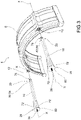
- reference numeral 4 indicates a mudguard unit as a whole.
- the mudguard unit 4 comprises a mudguard 8 having the shape of an arc of a circle around a transversal axis X-X, parallel to a thickness or depth of an associable vehicle wheel (not shown).
- the mudguard can be made of any material, preferably a plastic material.
- the mudguard 4 has at least one hollow fixing seat 12 parallel to said transversal axis X-X.
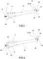
- the mudguard unit 4 comprises at least one support rod 16, parallel to said transversal axis X-X, and at least partially housed in said fixing seat 12.
- said at least one support rod 16 has circular geometry with respect to a plane of a section perpendicular to said transversal axis X-X.
- the support rod 16 extends from a distal end 20, at which it is fixed to the mudguard 8, to a proximal end 24, at which it is fixed to the chassis of an associable vehicle (not shown).
- Said support rod 16 is preferably made of aluminum or an alloy thereof.
- Said support rod 16 is preferably hollow.
- a bolt (28) is provided at the proximal end (24) having a head (32) and a threaded shank (36) for fixing into a hole in the chassis of an associable vehicle.
- a locking washer 40 having a circular body 44 provided with at least one appendage 48, which engages on a corresponding slot 52 on the proximal end 24 of the support rod 16 is integrally associated with the head 32 of the bolt 28 to join solidly the bolt 28 and the proximal end 24 of the support rod 16 itself.
- the coupling between the at least one appendage 48 and the corresponding slot 52 is an interlocking coupling.
- said appendage 48 has a radial extension prevailing over the circular body 44 of the locking washer 40.
- the slot 52 is made on a frontal portion 56 of the proximal end 24.
- the locking washer 40 comprises a plurality of appendages 48, which engage by interlocking in corresponding slots 52 of the proximal end 24.
- the bolt 28 and said locking washer 40 are made of iron or steel.
- the bolt 28 and locking washer are made of the same material and are welded together.
- a fixing base 60 to an associable vehicle chassis, is associated with the threaded shank 36 of the bolt 28, on the part opposite to the head 32, provided with a through-hole 64 for the threaded shank 36 of the bolt 28 and at least one locking nut 68, preferably provided with a respective backing washer 70.
- the support rod 16 on the proximal end side 24, is associated with at least one reinforcing rib 72, directed radially with respect to the bolt 28.
- said at least one reinforcing rib 72 is aligned with respect to said at least one appendage 48.
- the reinforcing rib 72 is welded to the support rod 16 and a fixing base 60 for the bolt 28 provided with a through-hole 64 through the threaded shank 36 of the bolt 28.
- the support rod 16, at said distal end 20, comprises an elastic head 76, elastically deformable so as to achieve a positive coupling with the fixing seat 12 of the mudguard 8.
- said elastic head 76 is shaped so as to make a snap-fit coupling with said fixing seat 12.
- the elastic head 76 comprises elastically deformable first fins 80 for fixing the elastic head 76 in respective holes 84 made on the support rod 16.
- the elastic head 76 comprises elastically deformable second fins 88 for the undercut locking of the elastic head 76 onto a base plate 92 of the mudguard 8 which delimits said fixing seat 12.
- the support rod 16 once pre-assembled ( figure 3 ), can be fixed to the vehicle chassis (not shown) by interposing the backing washer 70 and locking nut from the inside of the chassis (not shown).
- the support rod 16 can be fixed to the chassis by a single operator who simply needs to insert the threaded shank 36 into the appropriate seat in the chassis and lock it by means of locking nut 68 and its backing washer 70.
- the mudguard 8 can be attached to the support rod 16 by simply inserting the fixing seat 12 of the mudguard 8 from the side of the distal end 20 provided with the elastic head 76.
- the mudguard unit according to the present invention makes it possible to be assembled and disassembled extremely quickly.
- Said speed is due to the threaded coupling for fixing the support to the vehicle chassis and the snap-fit quick coupling, which makes it possible to constrain the mudguard to the support tube and then disassemble it.
- the solution of the present invention is extremely light. Indeed, the aluminum support tube is significantly lighter than the steel tube of the prior art.
- the solution of the present invention is extremely strong and robust; indeed, the aluminum tube is fixed to the chassis by means of an iron or steel screw with a respective special washer made of the same material specially shaped to be interlocked into the seats made in the aluminum tube.
- the support of the present invention compared to known solutions has the advantage of not requiring the use of a long wrench to be inserted internally along the length of the tube to tighten the screw on the chassis, which would require two operators.
- the assembly operations of the mudguard unit of the present invention can be carried out by a single operator, thus very quickly, by virtue of the connection screw to the chassis already present on one end of the bracket.
Landscapes
- Engineering & Computer Science (AREA)
- Chemical & Material Sciences (AREA)
- Combustion & Propulsion (AREA)
- Transportation (AREA)
- Mechanical Engineering (AREA)
- Body Structure For Vehicles (AREA)
Applications Claiming Priority (1)
| Application Number | Priority Date | Filing Date | Title |
|---|---|---|---|
| IT102021000015761A IT202100015761A1 (it) | 2021-06-16 | 2021-06-16 | Gruppo parafango per automezzi |
Publications (3)
| Publication Number | Publication Date |
|---|---|
| EP4105109A1 true EP4105109A1 (fr) | 2022-12-21 |
| EP4105109C0 EP4105109C0 (fr) | 2023-12-27 |
| EP4105109B1 EP4105109B1 (fr) | 2023-12-27 |
Family
ID=77801894
Family Applications (1)
| Application Number | Title | Priority Date | Filing Date |
|---|---|---|---|
| EP22173993.1A Active EP4105109B1 (fr) | 2021-06-16 | 2022-05-18 | Unité de garde-boue pour véhicules à moteur |
Country Status (2)
| Country | Link |
|---|---|
| EP (1) | EP4105109B1 (fr) |
| IT (1) | IT202100015761A1 (fr) |
Cited By (1)
| Publication number | Priority date | Publication date | Assignee | Title |
|---|---|---|---|---|
| US20220144346A1 (en) * | 2019-03-26 | 2022-05-12 | Komatsu Ltd. | Work vehicle and method for attaching/detaching mud guard |
Citations (5)
| Publication number | Priority date | Publication date | Assignee | Title |
|---|---|---|---|---|
| US3804542A (en) * | 1972-11-15 | 1974-04-16 | L Hammerschmidt | Joint construction |
| US4148373A (en) * | 1977-06-30 | 1979-04-10 | Cline Erving H | Fender support |
| EP1020346A1 (fr) * | 1999-01-12 | 2000-07-19 | Polyrim | Dispositif de support pour garde-boue de véhicule routier ou agricole |
| WO2004056640A1 (fr) * | 2002-12-23 | 2004-07-08 | Domar S.R.L. | Garde-boue pour vehicules a moteur comprenant un moyen de fixation a montage/demontage rapide |
| EP3680152A1 (fr) * | 2019-01-10 | 2020-07-15 | DOMAR S.p.A. | Couplage rapide pour coupler un garde-boue à un cadre |
-
2021
- 2021-06-16 IT IT102021000015761A patent/IT202100015761A1/it unknown
-
2022
- 2022-05-18 EP EP22173993.1A patent/EP4105109B1/fr active Active
Patent Citations (5)
| Publication number | Priority date | Publication date | Assignee | Title |
|---|---|---|---|---|
| US3804542A (en) * | 1972-11-15 | 1974-04-16 | L Hammerschmidt | Joint construction |
| US4148373A (en) * | 1977-06-30 | 1979-04-10 | Cline Erving H | Fender support |
| EP1020346A1 (fr) * | 1999-01-12 | 2000-07-19 | Polyrim | Dispositif de support pour garde-boue de véhicule routier ou agricole |
| WO2004056640A1 (fr) * | 2002-12-23 | 2004-07-08 | Domar S.R.L. | Garde-boue pour vehicules a moteur comprenant un moyen de fixation a montage/demontage rapide |
| EP3680152A1 (fr) * | 2019-01-10 | 2020-07-15 | DOMAR S.p.A. | Couplage rapide pour coupler un garde-boue à un cadre |
Cited By (1)
| Publication number | Priority date | Publication date | Assignee | Title |
|---|---|---|---|---|
| US20220144346A1 (en) * | 2019-03-26 | 2022-05-12 | Komatsu Ltd. | Work vehicle and method for attaching/detaching mud guard |
Also Published As
| Publication number | Publication date |
|---|---|
| EP4105109C0 (fr) | 2023-12-27 |
| EP4105109B1 (fr) | 2023-12-27 |
| IT202100015761A1 (it) | 2022-12-16 |
Similar Documents
| Publication | Publication Date | Title |
|---|---|---|
| US7900942B2 (en) | Wheel suspension arm | |
| US4377294A (en) | Vehicle fender and support bar | |
| US9616706B2 (en) | Adapter for dual-wheel vehicle | |
| US9650939B2 (en) | Socket isolator mounting apparatus | |
| EP4105109B1 (fr) | Unité de garde-boue pour véhicules à moteur | |
| US9969211B2 (en) | Mounting arrangement for installing auxiliary vehicle wheels | |
| US8657316B1 (en) | Rear axle support assembly | |
| US20070295157A1 (en) | Crankset assembly for a bicycle | |
| CN107848584B (zh) | 用于机动车辆的布局及机动车辆 | |
| US6910669B2 (en) | Spare tire bracket | |
| US8517422B2 (en) | Steering wheel alignment system | |
| US20020167148A1 (en) | Rear suspension for vehicles | |
| GB2333501A (en) | Support assembly for mounting functional units of a motor vehicle | |
| JP5120115B2 (ja) | ステアリングコラムの支持装置 | |
| JPH10157427A (ja) | ホイールサスペンション | |
| JP5267447B2 (ja) | ステアリングコラムの支持装置 | |
| US4925248A (en) | Track-adjusting wheel | |
| KR101685397B1 (ko) | 차량의 서브 프레임용 마운팅 유닛 | |
| US7055406B1 (en) | Axle housing assembly | |
| US4938500A (en) | Air bag mounting system for motor vehicles | |
| US20100072749A1 (en) | Clamp collar | |
| US20070267839A1 (en) | Combination spring, shock and brake cable bracket | |
| JP6680184B2 (ja) | 車両用部材取付構造 | |
| US20130269468A1 (en) | Height-Adjustable Safety Steering Column Assembly | |
| US5938239A (en) | Motor vehicle steering column assembly unit |
Legal Events
| Date | Code | Title | Description |
|---|---|---|---|
| PUAI | Public reference made under article 153(3) epc to a published international application that has entered the european phase |
Free format text: ORIGINAL CODE: 0009012 |
|
| STAA | Information on the status of an ep patent application or granted ep patent |
Free format text: STATUS: THE APPLICATION HAS BEEN PUBLISHED |
|
| AK | Designated contracting states |
Kind code of ref document: A1 Designated state(s): AL AT BE BG CH CY CZ DE DK EE ES FI FR GB GR HR HU IE IS IT LI LT LU LV MC MK MT NL NO PL PT RO RS SE SI SK SM TR |
|
| STAA | Information on the status of an ep patent application or granted ep patent |
Free format text: STATUS: REQUEST FOR EXAMINATION WAS MADE |
|
| 17P | Request for examination filed |
Effective date: 20230321 |
|
| RBV | Designated contracting states (corrected) |
Designated state(s): AL AT BE BG CH CY CZ DE DK EE ES FI FR GB GR HR HU IE IS IT LI LT LU LV MC MK MT NL NO PL PT RO RS SE SI SK SM TR |
|
| GRAP | Despatch of communication of intention to grant a patent |
Free format text: ORIGINAL CODE: EPIDOSNIGR1 |
|
| STAA | Information on the status of an ep patent application or granted ep patent |
Free format text: STATUS: GRANT OF PATENT IS INTENDED |
|
| INTG | Intention to grant announced |
Effective date: 20230726 |
|
| GRAS | Grant fee paid |
Free format text: ORIGINAL CODE: EPIDOSNIGR3 |
|
| GRAA | (expected) grant |
Free format text: ORIGINAL CODE: 0009210 |
|
| STAA | Information on the status of an ep patent application or granted ep patent |
Free format text: STATUS: THE PATENT HAS BEEN GRANTED |
|
| AK | Designated contracting states |
Kind code of ref document: B1 Designated state(s): AL AT BE BG CH CY CZ DE DK EE ES FI FR GB GR HR HU IE IS IT LI LT LU LV MC MK MT NL NO PL PT RO RS SE SI SK SM TR |
|
| REG | Reference to a national code |
Ref country code: GB Ref legal event code: FG4D |
|
| REG | Reference to a national code |
Ref country code: CH Ref legal event code: EP |
|
| REG | Reference to a national code |
Ref country code: DE Ref legal event code: R096 Ref document number: 602022001463 Country of ref document: DE |
|
| REG | Reference to a national code |
Ref country code: IE Ref legal event code: FG4D |
|
| U01 | Request for unitary effect filed |
Effective date: 20240123 |
|
| U07 | Unitary effect registered |
Designated state(s): AT BE BG DE DK EE FI FR IT LT LU LV MT NL PT SE SI Effective date: 20240131 |
|
| PG25 | Lapsed in a contracting state [announced via postgrant information from national office to epo] |
Ref country code: GR Free format text: LAPSE BECAUSE OF FAILURE TO SUBMIT A TRANSLATION OF THE DESCRIPTION OR TO PAY THE FEE WITHIN THE PRESCRIBED TIME-LIMIT Effective date: 20240328 |
|
| U20 | Renewal fee for the european patent with unitary effect paid |
Year of fee payment: 3 Effective date: 20240321 |
|
| PG25 | Lapsed in a contracting state [announced via postgrant information from national office to epo] |
Ref country code: ES Free format text: LAPSE BECAUSE OF FAILURE TO SUBMIT A TRANSLATION OF THE DESCRIPTION OR TO PAY THE FEE WITHIN THE PRESCRIBED TIME-LIMIT Effective date: 20231227 |
|
| PG25 | Lapsed in a contracting state [announced via postgrant information from national office to epo] |
Ref country code: GR Free format text: LAPSE BECAUSE OF FAILURE TO SUBMIT A TRANSLATION OF THE DESCRIPTION OR TO PAY THE FEE WITHIN THE PRESCRIBED TIME-LIMIT Effective date: 20240328 Ref country code: ES Free format text: LAPSE BECAUSE OF FAILURE TO SUBMIT A TRANSLATION OF THE DESCRIPTION OR TO PAY THE FEE WITHIN THE PRESCRIBED TIME-LIMIT Effective date: 20231227 |
|
| PG25 | Lapsed in a contracting state [announced via postgrant information from national office to epo] |
Ref country code: RS Free format text: LAPSE BECAUSE OF FAILURE TO SUBMIT A TRANSLATION OF THE DESCRIPTION OR TO PAY THE FEE WITHIN THE PRESCRIBED TIME-LIMIT Effective date: 20231227 Ref country code: NO Free format text: LAPSE BECAUSE OF FAILURE TO SUBMIT A TRANSLATION OF THE DESCRIPTION OR TO PAY THE FEE WITHIN THE PRESCRIBED TIME-LIMIT Effective date: 20240327 Ref country code: HR Free format text: LAPSE BECAUSE OF FAILURE TO SUBMIT A TRANSLATION OF THE DESCRIPTION OR TO PAY THE FEE WITHIN THE PRESCRIBED TIME-LIMIT Effective date: 20231227 |
|
| PG25 | Lapsed in a contracting state [announced via postgrant information from national office to epo] |
Ref country code: IS Free format text: LAPSE BECAUSE OF FAILURE TO SUBMIT A TRANSLATION OF THE DESCRIPTION OR TO PAY THE FEE WITHIN THE PRESCRIBED TIME-LIMIT Effective date: 20240427 |
|
| PG25 | Lapsed in a contracting state [announced via postgrant information from national office to epo] |
Ref country code: CZ Free format text: LAPSE BECAUSE OF FAILURE TO SUBMIT A TRANSLATION OF THE DESCRIPTION OR TO PAY THE FEE WITHIN THE PRESCRIBED TIME-LIMIT Effective date: 20231227 |
|
| PG25 | Lapsed in a contracting state [announced via postgrant information from national office to epo] |
Ref country code: SK Free format text: LAPSE BECAUSE OF FAILURE TO SUBMIT A TRANSLATION OF THE DESCRIPTION OR TO PAY THE FEE WITHIN THE PRESCRIBED TIME-LIMIT Effective date: 20231227 |
|
| PG25 | Lapsed in a contracting state [announced via postgrant information from national office to epo] |
Ref country code: SM Free format text: LAPSE BECAUSE OF FAILURE TO SUBMIT A TRANSLATION OF THE DESCRIPTION OR TO PAY THE FEE WITHIN THE PRESCRIBED TIME-LIMIT Effective date: 20231227 Ref country code: SK Free format text: LAPSE BECAUSE OF FAILURE TO SUBMIT A TRANSLATION OF THE DESCRIPTION OR TO PAY THE FEE WITHIN THE PRESCRIBED TIME-LIMIT Effective date: 20231227 Ref country code: RO Free format text: LAPSE BECAUSE OF FAILURE TO SUBMIT A TRANSLATION OF THE DESCRIPTION OR TO PAY THE FEE WITHIN THE PRESCRIBED TIME-LIMIT Effective date: 20231227 Ref country code: IS Free format text: LAPSE BECAUSE OF FAILURE TO SUBMIT A TRANSLATION OF THE DESCRIPTION OR TO PAY THE FEE WITHIN THE PRESCRIBED TIME-LIMIT Effective date: 20240427 Ref country code: CZ Free format text: LAPSE BECAUSE OF FAILURE TO SUBMIT A TRANSLATION OF THE DESCRIPTION OR TO PAY THE FEE WITHIN THE PRESCRIBED TIME-LIMIT Effective date: 20231227 |
|
| PG25 | Lapsed in a contracting state [announced via postgrant information from national office to epo] |
Ref country code: PL Free format text: LAPSE BECAUSE OF FAILURE TO SUBMIT A TRANSLATION OF THE DESCRIPTION OR TO PAY THE FEE WITHIN THE PRESCRIBED TIME-LIMIT Effective date: 20231227 |
|
| PG25 | Lapsed in a contracting state [announced via postgrant information from national office to epo] |
Ref country code: PL Free format text: LAPSE BECAUSE OF FAILURE TO SUBMIT A TRANSLATION OF THE DESCRIPTION OR TO PAY THE FEE WITHIN THE PRESCRIBED TIME-LIMIT Effective date: 20231227 |
|
| REG | Reference to a national code |
Ref country code: DE Ref legal event code: R097 Ref document number: 602022001463 Country of ref document: DE |
|
| PLBE | No opposition filed within time limit |
Free format text: ORIGINAL CODE: 0009261 |
|
| STAA | Information on the status of an ep patent application or granted ep patent |
Free format text: STATUS: NO OPPOSITION FILED WITHIN TIME LIMIT |
|
| 26N | No opposition filed |
Effective date: 20240930 |
|
| PG25 | Lapsed in a contracting state [announced via postgrant information from national office to epo] |
Ref country code: MC Free format text: LAPSE BECAUSE OF FAILURE TO SUBMIT A TRANSLATION OF THE DESCRIPTION OR TO PAY THE FEE WITHIN THE PRESCRIBED TIME-LIMIT Effective date: 20231227 |
|
| PG25 | Lapsed in a contracting state [announced via postgrant information from national office to epo] |
Ref country code: MC Free format text: LAPSE BECAUSE OF FAILURE TO SUBMIT A TRANSLATION OF THE DESCRIPTION OR TO PAY THE FEE WITHIN THE PRESCRIBED TIME-LIMIT Effective date: 20231227 |
|
| PG25 | Lapsed in a contracting state [announced via postgrant information from national office to epo] |
Ref country code: IE Free format text: LAPSE BECAUSE OF NON-PAYMENT OF DUE FEES Effective date: 20240518 |
|
| U20 | Renewal fee for the european patent with unitary effect paid |
Year of fee payment: 4 Effective date: 20250324 |
|
| PG25 | Lapsed in a contracting state [announced via postgrant information from national office to epo] |
Ref country code: CY Free format text: LAPSE BECAUSE OF FAILURE TO SUBMIT A TRANSLATION OF THE DESCRIPTION OR TO PAY THE FEE WITHIN THE PRESCRIBED TIME-LIMIT; INVALID AB INITIO Effective date: 20220518 |
|
| PG25 | Lapsed in a contracting state [announced via postgrant information from national office to epo] |
Ref country code: HU Free format text: LAPSE BECAUSE OF FAILURE TO SUBMIT A TRANSLATION OF THE DESCRIPTION OR TO PAY THE FEE WITHIN THE PRESCRIBED TIME-LIMIT; INVALID AB INITIO Effective date: 20220518 |
|
| REG | Reference to a national code |
Ref country code: CH Ref legal event code: H13 Free format text: ST27 STATUS EVENT CODE: U-0-0-H10-H13 (AS PROVIDED BY THE NATIONAL OFFICE) Effective date: 20251223 |
|
| PG25 | Lapsed in a contracting state [announced via postgrant information from national office to epo] |
Ref country code: CH Free format text: LAPSE BECAUSE OF NON-PAYMENT OF DUE FEES Effective date: 20250531 |
|
| U20 | Renewal fee for the european patent with unitary effect paid |
Year of fee payment: 5 Effective date: 20260325 |