EP4105111A1 - Dispositif de blocage de disques de frein - Google Patents
Dispositif de blocage de disques de frein Download PDFInfo
- Publication number
- EP4105111A1 EP4105111A1 EP22176500.1A EP22176500A EP4105111A1 EP 4105111 A1 EP4105111 A1 EP 4105111A1 EP 22176500 A EP22176500 A EP 22176500A EP 4105111 A1 EP4105111 A1 EP 4105111A1
- Authority
- EP
- European Patent Office
- Prior art keywords
- claw
- brake disc
- section
- lock
- disc lock
- Prior art date
- Legal status (The legal status is an assumption and is not a legal conclusion. Google has not performed a legal analysis and makes no representation as to the accuracy of the status listed.)
- Granted
Links
Images


Classifications
-
- B—PERFORMING OPERATIONS; TRANSPORTING
- B62—LAND VEHICLES FOR TRAVELLING OTHERWISE THAN ON RAILS
- B62H—CYCLE STANDS; SUPPORTS OR HOLDERS FOR PARKING OR STORING CYCLES; APPLIANCES PREVENTING OR INDICATING UNAUTHORIZED USE OR THEFT OF CYCLES; LOCKS INTEGRAL WITH CYCLES; DEVICES FOR LEARNING TO RIDE CYCLES
- B62H5/00—Appliances preventing or indicating unauthorised use or theft of cycles; Locks integral with cycles
- B62H5/14—Appliances preventing or indicating unauthorised use or theft of cycles; Locks integral with cycles preventing wheel rotation
- B62H5/18—Appliances preventing or indicating unauthorised use or theft of cycles; Locks integral with cycles preventing wheel rotation acting on a braking device
-
- B—PERFORMING OPERATIONS; TRANSPORTING
- B62—LAND VEHICLES FOR TRAVELLING OTHERWISE THAN ON RAILS
- B62H—CYCLE STANDS; SUPPORTS OR HOLDERS FOR PARKING OR STORING CYCLES; APPLIANCES PREVENTING OR INDICATING UNAUTHORIZED USE OR THEFT OF CYCLES; LOCKS INTEGRAL WITH CYCLES; DEVICES FOR LEARNING TO RIDE CYCLES
- B62H5/00—Appliances preventing or indicating unauthorised use or theft of cycles; Locks integral with cycles
- B62H5/20—Appliances preventing or indicating unauthorised use or theft of cycles; Locks integral with cycles indicating unauthorised use, e.g. acting on signalling devices
-
- E—FIXED CONSTRUCTIONS
- E05—LOCKS; KEYS; WINDOW OR DOOR FITTINGS; SAFES
- E05B—LOCKS; ACCESSORIES THEREFOR; HANDCUFFS
- E05B15/00—Other details of locks; Parts for engagement by bolts of fastening devices
-
- E—FIXED CONSTRUCTIONS
- E05—LOCKS; KEYS; WINDOW OR DOOR FITTINGS; SAFES
- E05B—LOCKS; ACCESSORIES THEREFOR; HANDCUFFS
- E05B15/00—Other details of locks; Parts for engagement by bolts of fastening devices
- E05B15/10—Bolts of locks or night latches
Definitions
- the invention relates to a brake disc lock with a claw that has a first claw section and a second claw section.
- the first claw section and the second claw section can be moved relative to one another between an open position and a closed position of the claw.
- the claw In the closed position, the claw has a predetermined clear width in order to encompass a section of a brake disc of a bicycle.
- the claw comprises a locking mechanism which is designed to lock the claw in the closed position.
- a brake disc lock is used to secure a two-wheeler against unauthorized driving away by blocking a brake disc of the two-wheeler from rotating.
- the brake disc lock can engage in an opening in the brake disc, which is formed on the brake disc for ventilation/cooling purposes or to save weight.
- Such a brake disc lock can have, for example, a receiving gap in which the brake disc is received and which is then penetrated in the transverse direction by a bolt in order to secure the brake disc lock on the brake disc.
- the operation of such a brake disc lock can be undesirably complicated. In particular, operation with two hands may be necessary if the receiving gap of the brake disc lock has to be aligned relative to the brake disc with one hand in order to be able to actuate the locking device with the other hand so that the bolt hits the associated opening of the brake disc.
- the claw has a predetermined clear width in the closed position in order to encompass a section of a brake disc of a bicycle. In this closed position with a predetermined clearance, the claw can be locked.
- the brake disc lock also has an adjustment device which is designed to adapt the predetermined clear width of the claw to different brake discs.
- the relevant section of the brake disk can be encompassed by the claw in that one of the two claw sections engages in an opening in the brake disk and the other of the two claw sections encompasses an outer circumference of the brake disk or engages in another opening in the brake disk.
- the claw thus forms a receiving space for the in the closed position relevant section of the brake disc.
- the specified clear width of the claw refers to the effective internal dimension of the claw in its closed position.
- the clear width of the claw should generally correspond as closely as possible to the extent of the brake disc section encompassed, ie the claw should be attached to the section of the brake disc with little play so that the brake disc lock is securely seated on the brake disc.
- the clear width with which the claw effectively delimits the receiving space for the brake disc in the closed position can be adjusted, i.e. the clear width is predetermined for subsequent use of the brake disc lock and is retained during subsequent use.
- the clear width of the claw for the subsequent use of the brake disc lock can thus be adjusted to the dimensions of a specific brake disc—in particular to the extension of the section of the brake disc to be encompassed—by means of the adjustment device.
- This adjustment of the predetermined clear width of the claw thus relates to the subsequent repeated closing of the brake disc lock on the relevant brake disc and release from this brake disc.
- the design of the brake disc lock makes it possible in particular to use the brake disc lock on different vehicles with at least two wheels, such as on a motorcycle, a scooter, an e-bike, a cargo bike, a bicycle, a trike, a quad and the like.
- the adaptability of the predetermined clear width of the claw can in particular prevent the brake disc lock from being able to be detached from the brake disc by slightly bending it open, for example because the ends of the two claw sections are too far apart. Furthermore, it can be prevented or at least made more difficult that a breaking tool (for example for levering open) can be inserted into a space between the brake disc and the brake disc lock due to excessive play.
- An advantage of the invention is that it is easy to use and fail-safe.
- the predetermined clear width of the claw is always maintained, since locking only takes place in the closed position of the claw. Reliable attachment of the claw to the brake disc is thus ensured by adequate gripping in the closed position with little play, without the user having to ensure that the claw is always closed with the maximum possible stroke.
- Due to the claw shape the brake disc lock can be hung on the brake disc in the open position. This means that one-handed operation is possible since the brake disc lock does not have to be held and aligned relative to the brake disc for locking.
- the locking mechanism can be firmly connected to the first claw section, at least when the brake disc lock is in use.
- the second claw portion can be moveable relative to the first claw portion and to the locking mechanism to move the claw between the open position and the closed position.
- the brake disc lock can also have a lock body in which the locking mechanism is held and on which the second claw section is movably guided.
- the first claw section can also be referred to as a holding section and the second claw section as a closing section.
- first claw portion and the second claw portion may be linearly movable relative to one another between the open position and the closed position.
- first claw portion and the second claw portion may each have a hook structure to engage the portion of the brake disc.
- the claw can in particular be essentially C-shaped.
- At least one of the claw sections can have a hook structure which is designed to encompass the section of the brake disc and which is at an effective distance from the locking mechanism (and thus in particular from a lock body of the brake disc lock) when the claw is closed and locked .
- the adjustment device can be designed to adjust the effective distance of the hook structure from the locking mechanism or from the lock body. Said effective distance can in particular relate to the direction of movement of the claw.
- a fastening position of said holding section of the claw can be adjustable, or said holding section or said closing section of the claw can be adjustable in length.
- the first claw portion in a state of use of the brake disc latch, may be fixed in an adjustable fixed mounting position relative to the locking mechanism.
- the adjuster may be configured to adjust the attachment position of the first claw portion relative to the locking mechanism.
- This attachment position may be a position that the first claw portion in the subsequent use of the brake disc lock for repeated locking to the brake disc in question and disengagement from the brake disc on the locking mechanism and maintains it during use, ie in particular also during the movement of the claw between the open position and the closed position.
- the brake disc lock may include a bracket that supports the locking mechanism, and the first claw portion may be attached to the bracket.
- the holder can be formed in particular by the lock body mentioned.
- the adjustment device can be designed to adjust the predetermined clear width of the claw based on a positive connection between two components of the brake disc lock (e.g. between a claw section and the locking mechanism, or between two claw sections) according to a predetermined grid.
- a positive connection between two components of the brake disc lock (e.g. between a claw section and the locking mechanism, or between two claw sections) according to a predetermined grid.
- a particularly high degree of security of the adjustable connection against attempts to break open can be achieved by means of a form fit.
- a predetermined grid of the positive connection simplifies the adjustment of the clear width by the user.
- the adjustment device can have an engagement contour (eg toothing) assigned to the locking mechanism and an engagement counter-contour (eg counter-toothing) assigned to the first claw section.
- the engagement contour and the engagement counter-contour can be brought into engagement with one another in different fastening positions and can be secured to one another in the respective fastening position.
- the various fastening positions can therefore be used to set the predetermined clear width of the claw in the closed position for subsequent use of the brake disc lock.
- Said engagement contour does not have to be formed directly on the locking mechanism, but can be formed, for example, on said holder or on said lock body of the brake disc lock can be provided.
- the engagement contour and the engagement counter-contour can have a plurality of teeth which, for example, taper to a point, in particular have a sawtooth shape, or are rectangular in cross-section, with incremental adjustment being made possible. Securing in the respective fastening position can take place in particular by means of a securing element, which is described in more detail below.
- the adjustment device can, for example, have a row of holes for screw fasteners according to a predetermined grid, in which case, for example, a threaded hole can be aligned with one of several through-openings or a through-opening with one of several threaded holes can be brought into alignment, and the respective threaded hole on the one hand and the respective passage opening on the other hand are assigned to the locking mechanism or the first claw section, or vice versa.
- the first claw section can be rigid and/or have a fixed length.
- the first claw section can in particular correspond to the mentioned holding section of the claw.
- the at least one claw portion having the hook structure can have a locking structure with which the locking mechanism is engaged when the claw is closed and locked.
- the adjuster may be configured to adjust an effective length between the hook structure and the locking structure of the claw portion.
- the relevant claw section can be positioned relative to the other claw section and/or to the locking mechanism (or Lock body) be movable to move the claw between the open position and the closed position.
- the claw section in question can thus in particular correspond to the said closing section of the claw, which is length-adjustable in this embodiment.
- the brake disc lock can have a holder that supports the locking mechanism, wherein the at least one claw portion having the hook structure has a connecting end at which the claw portion is connected to the holder in a fixed position (integral formed in one piece or permanently connected in several parts).
- the adjuster may be configured to adjust an effective length between the hook structure and the connecting end of the claw portion.
- the holder can be formed in particular by the lock body mentioned.
- the relevant claw section can be arranged immovably when the claw is moved between the open position and the closed position.
- the claw section in question can in particular correspond to the named holding section of the claw, which is length-adjustable in this embodiment.
- the adjustment device can have, for example, a threaded rod and an internal thread that can be displaced along the threaded rod, by means of which the effective length of the at least one claw section can be adjusted.
- the effective length can be achieved by rotating the threaded rod and the internal thread relative to one another in small increments.
- the threaded rod may be connected to the hook structure and the internal threads may be connected to the locking structure or the attachment end of the claw portion, or vice versa.
- the adjustment device (with threaded rod and internal thread) can thus be part of the length-adjustable claw section.
- the brake disc lock can be designed such that the adjustment device can only be actuated as a result of an unlocking of the locking mechanism in order to adapt the predetermined clear width of the claw to different brake discs. It is therefore first necessary for the authorized user to unlock the brake disc lock or the locking mechanism using an assigned means of identification (e.g. using a key or by entering or transmitting a code, in particular by radio).
- the adjustment device can only be actuated after the brake disc lock has been unlocked, for example by the adjustment device being accessible only when the claw is in the open position or when the brake disc lock is released from the brake disc, as will be explained below. This prevents the brake disc lock from being released from the brake disc by manipulating the adjustment device.
- the adjustment means may include a locking member configured to lock an adjustment (i.e., a set value) of the predetermined clearance of the claw.
- the securing element may be obscured by the brake disc or by a part of the brake disc lock and/or the securing element may be blocked against movement when the brake disc lock is attached to the brake disc and when the claw is closed and locked.
- the securing element can, for example, comprise at least one screw or nut that secures a position of another element of the adjustment device, the screw or nut being secured against displacement by the claw itself when the claw is in the closed position.
- the securing element can be a metal pin secured against displacement, for example.
- the claw may be biased toward the open position.
- the preload can be by a coil spring, torsion spring or wave spring can be achieved. Due to such a preload, the claw can automatically move into the open position after unlocking, so that the user can easily see when the claw is in the open position. Furthermore, the open position is assumed to be stable due to the pretension. This simplifies the application of the brake disc lock to the brake disc (in particular the explained hanging) and/or one-handed operation.
- the locking mechanism can have a bolt which, in a locking position—when the claw is closed—locks the second claw section on the first claw section and in a release position releases the second claw section for movement relative to the first claw section.
- the locking mechanism may include a key cylinder to operate the bolt.
- the bolt can be pretensioned in the direction of the locking position, the bolt being designed to be pushed back in the direction of the release position by moving the claw from the open position into the closed position and then to snap into the locking position due to the pretension.
- the bolt can be prestressed, for example, by a spiral or torsion spring, which acts on the bolt with one end and is supported with the other end on a housing of the locking mechanism and/or on the said lock body.
- the preload causes an automatic function of the locking of the brake disc lock, so that the lock cylinder does not have to be actuated manually to lock the lock. This in turn simplifies the aforementioned one-handed operation of the brake disc lock.
- the bolt can be rotatably mounted and have a lateral surface with a tangential recess, the recess releasing a locking elevation of the second claw section when the bolt is in the release position.
- the bolt can thus be designed as a rotary bolt which is rotatably mounted, for example, on a lateral surface of the lock cylinder.
- the axis of rotation of the rotating bolt can coincide with an axis of rotation of the lock cylinder.
- an electromechanical locking mechanism can also be provided, for example with an electric motor or electromagnet as an electrically controllable actuator.
- At least one of the claw sections in particular the first claw section—can be designed to engage in an opening in the brake disc and thereby keep the brake disc lock hanging on the brake disc.
- the brake disc lock can also be arranged hanging freely on the brake disc when the claw is in the open position, without the user having to hold and position the brake disc lock with one hand in order to be able to actuate the locking mechanism with the other hand.
- the already mentioned hook structure can be formed on the relevant claw section.
- the brake disc lock can have an alarm device for emitting an alarm signal, the alarm device being configured to be activated by moving the claw to the closed position and to be deactivated by moving the claw from the closed position to the open position. This can be achieved that the alarm device is automatically activated and deactivated when the user Claw moves between the closed position and the open position, in particular as a result of an unlocking actuation of the locking mechanism.
- the alarm device can include a motion sensor that detects changes in position and/or acceleration or changes in acceleration, which trigger the output of an alarm signal when a threshold value is exceeded, for example.
- the acceleration sensor can also emit an acoustic alarm signal as protection against forgetting when the bicycle is moved by the authorized user without having released the brake disc lock from the brake disc. Furthermore, when the alarm device is activated, a short activation tone can be heard, which acoustically confirms the activation of the alarm function.
- the alarm device can have an activation switch which is designed to be actuated automatically when the claw is in the closed position by the second claw section or by a part of the brake disc lock connected to the second claw section.
- the activation switch can be designed in particular as a contact switch.
- the activation of the alarm device can be triggered, for example, by interacting actuating bevels on the second claw section and on the alarm device. If the activation switch is no longer actuated with the claw in the open position, this can trigger the deactivation of the alarm device.
- the evaluation of the signals from the motion sensor mentioned and/or the activation switch mentioned can be carried out by a control circuit of the alarm device.
- the alarm device can be arranged in a housing section of the brake disc lock, which is firmly connected to the first claw section, the alarm device only as a result an unlocking of the locking mechanism is accessible. This ensures that the alarm device (for example for a battery change) is only accessible to the authorized user who has the identification means assigned to the locking mechanism (eg key).
- the housing section of the brake disc lock can have an access opening through which the alarm device can be accessed.
- the brake disk lock can be designed such that the access opening is covered by the second claw section when the claw is in the closed position. In the open position of the claw, on the other hand, the access opening can be released for access.
- the access opening can be covered, for example, by a cover that can only be opened when the brake disc lock is in the unlocked state. This ensures inherent protection of the alarm device against attempts at manipulation.
- the brake disc lock can have a first security section associated with the first claw section and a second security section associated with the second claw section.
- the first securing section and the second securing section can form a receiving opening for inserting an eyelet of a flexible securing part, in particular a chain.
- the first securing section and the second securing section can form a circumferentially closed delimitation of the receiving opening in order to secure the inserted eyelet on the brake disc lock.
- One of the two securing sections can be formed, for example, by part of a lock body of the brake disk lock.
- the brake disc lock can therefore not only be used to block a brake disc of the two-wheeler, but also to fix the two-wheeler to a Environment object and / or to secure other objects (e.g. helmet) are used on the two-wheeler.
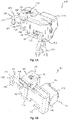
- FIG. 1A shows the back of a brake disc lock 100 in a perspective view in a closed position.
- the brake disk lock 100 comprises a lock body 114 and a claw 102 which has a first claw section 104 and a second claw section 106 .
- the first claw portion 104 is in a use state of the brake disc lock 100 is held immovably on the lock body 114, and the second claw section 106 is movably guided on the lock body 114 and can be locked in the closed position of the claw 102.
- the first claw section 104 and the second claw section 106 form a respective hook structure 105 or 107 at their free ends.
- the lock body 114 can be formed by a metal casting (eg zinc die casting).
- the first claw section 104 and the second claw section 106 can be formed by stamped and bent metal parts.
- the brake disc lock 100 includes a first securing section 120 which is associated with the first claw section 104 and is formed by a part of the lock body 114 , and a second securing section 122 which is formed by a part of the second claw section 106 .
- the first securing section 120 and the second securing section 122 form a receiving opening 123 for inserting an eyelet of a flexible securing part 124.
- the first securing section 120 and the second securing section 122 form a circumferentially closed boundary of the receiving opening 123 to secure the inserted eyelet to the brake disc lock 100.
- FIG 1B shows a perspective view of the brake disc lock 100 in the closed position of the claw 102 without lock body 114.
- the brake disc lock 100 comprises a locking mechanism 108 which has a lock cylinder 126 within a two-part cylinder housing 125 and which is designed to lock the claw 102 in the closed position.
- the locking mechanism 108 has a rotating bolt 202, as in connection with FIG Figures 2A and 2B will be explained later.
- the locking mechanism 108 is arranged within the lock body 114, which insofar as a holder for holding the locking mechanism 108 and the first claw portion 104 and for guiding the movable second claw section 106.
- the brake disc lock 100 also includes an alarm device 110 which is housed in a housing section 132 ( Figure 1C ) of the brake disc lock 100 is arranged.
- the alarm device 110 has a housing 134, an activation switch 112, a motion sensor (not shown), a control circuit (not shown) and an acoustic signal generator 113 ( Figure 1B ).
- a cover 118 is designed to cover the open rear of the lock body 114 and thus the locking mechanism 108 and the alarm device 110 .
- the cover 118 is shown removed from its original position.
- the brake disc lock 100 can be attached to a brake disc of a bicycle (not shown) in an open position of the claw 102 by inserting the hook structure 105 of the first claw section 104 into an opening of the brake disc in order to encompass a section of the brake disc.
- brake disc lock 100 is aligned in a plane parallel to the extension plane of the brake disc, so that when brake disc lock 100 is released, the brake disc is supported at a first support point 116 of first claw section 104 and at a second support point 130 of lock body 114.
- the brake disc lock 100 is locked and secured to the brake disc. This is done by moving the second claw section 106 of the claw 102 in the direction of the first claw section 104 and the lock body 114, as will be explained in more detail below.
- Figures 2A and 2B show a sectional representation of parts of the brake disc lock 100 (without the lock body 114) in a plan view in the closed position and in the open position.
- the claw sections 104, 106 are movable relative to one another between an open position and a closed position of the claw 102.
- the claw 102 has in the closed position according to Figure 2A a predetermined clear width to encompass a portion of a brake disc of a two-wheeler.
- the clear width of the claw 102 denotes the internal dimension of the claw 102 in its closed position, i.e.
- the clear width of the claw 102 can generally also denote the internal dimension or the distance between the ends of the two claw sections 104, 106.
- the first claw section 104 of the claw 102 is fastened in an adjustable, fixed fastening position relative to the lock body 114 and thus relative to the locking mechanism 108 and the rotating bolt 202 already mentioned.
- An adjustment device 217 of the brake disc lock 100 is designed to be able to adapt the fastening position of the first claw section 104 relative to the locking mechanism 108 to different brake discs.
- the adjustment device 217 can be designed in such a way that it has an engagement contour in the form of teeth 218 assigned to the lock body 114 or the locking mechanism 108 and an engagement counter-contour in the form of counter-teeth 220 assigned to the first claw section 104 .
- the toothing 218 and the counter-toothing 220 can be fixed in different positions in Engaged brought together and fixed to each other.
- the teeth 218 associated with the locking mechanism 108 can be attached to the side of the lock body 114 facing the first claw section 104 .
- the counter-toothing 220 which is assigned to the first claw section 104, can be attached to the side of the first claw section 104 that faces the lock body 114.
- the set of teeth 218 and the counter-set of teeth 220 can be secured to one another by a securing element, embodied here by way of example as two securing screws 214 in order to fix the fastening position of the first claw section 104 .
- the adjustment device 217 is thus designed to adapt the predetermined clear width of the claw 102 to different brake disks.
- the locking screws 214 in the open position ( Figure 2B ) of the claw 102 can be loosened so that the mutual engagement of the toothing 218 and the counter-toothing 220 can be released.
- the clear width of the claw 102 can be adjusted by shifting the first claw section 104 to a desired position. Once in the desired position, the teeth 218 and counter teeth 220 can be re-engaged and secured together by the locking screws 214 .
- FIG 1C the two locking screws 214 are shown removed from their original position.
- the locking screws 214 are each inserted into a threaded bore 136 of the lock body 114 as soon as the toothing 218 and the counter-toothing 220 are in the desired fastening position of the first claw section 104 in engagement.
- the first claw section 104 and thus the counter-toothing 220 are pressed against the toothing 218 and secured against one another.
- the thus adapted fastening position of the first claw section 104 is a position that the first claw section 104 assumes in the subsequent use of the brake disc lock 100 for repeated locking on the relevant brake disc and releasing from the brake disc relative to the lock body 114 and thus relative to the locking mechanism 108 and maintained during use, ie in particular during the movement of the claw 102 between the open position and the closed position.
- the rotating bolt 202 which can be actuated by means of the lock cylinder 126, is designed to lock the claw 102 in the closed position ( Figure 2A ).
- the rotary latch 202 is biased towards its locking position, for example by a torsion spring (not shown). In the representation according to Figures 2A and 2B the bias is counterclockwise.
- the rotary bolt 202 is rotatably mounted on a lateral surface 222 of the lock cylinder 126, the axis of rotation of the rotary bolt 202 and the axis of rotation of the lock cylinder 126 coinciding.
- the rotary latch 202 has a tangential recess 208 on an outer cylindrical lateral surface 222 .
- the prestressed rotating bolt 202 is temporarily pushed back in the direction of a release position by a locking structure in the form of a locking elevation 204 of the second claw section 106.
- the locking elevation 204 acts on a boundary of the tangential recess 208 of the rotating bolt 202 .
- the brake disc lock 100 includes a return spring 206 in the form of a coil spring mounted between the second claw portion 106 and the cover 118 .
- the restoring spring 206 is preloaded by moving the second claw section 106 in the direction of the first claw section 104 .
- the second claw section 106 is pushed by the return spring 206 from the closed position into the open position of the claw 102 .
- the alarm device 110 of the brake disc latch 100 can be activated by moving the claw 102 from the open position to the closed position and deactivated by moving the claw 102 from the closed position to the open position.
- an activation elevation 216 of the second claw section 106 can actuate the activation switch 112, designed as a contact switch, of the alarm device 110 as soon as the claw 102 is brought from the open position into the closed position.
- the activation survey 216 can den Actuate activation switch 112 directly or indirectly.
- the activation elevation 216 can press a movable housing 134 of the alarm device 110 against the lock body 114 and thereby actuate the activation switch 112 of the alarm device 110. As long as the claw 102 is in the closed position, the alarm device 110 is activated.
- the activation switch 112 of the alarm device 110 is deactivated. This can be done either - in the case of direct actuation - by releasing the activation bump 216 from the activation switch 112, or - in the case of the indirect actuation shown - by pushing back the second claw section 106 and thus the activation bump 216 into the open position of the claw 102 134 of the alarm device 110 can move back into the starting position. As a result, the housing 134 of the alarm device 110 is no longer pressed against the lock body 114 and the activation switch 112 is deactivated.
- the housing 134 of the alarm device 110 can be reset by a restoring force, which is produced, for example, by compressing a silicone layer between the housing 134 of the alarm device 110 and the lock body 114 due to the contact pressure of the activation elevation 216 .
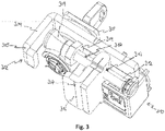
- FIG. 3 shows a perspective view of an alternative embodiment of a brake disc lock 100 with a first claw portion 304 and a second claw portion 306 of a claw 302; further with a locking mechanism 308 and with an alarm device 310.
- the first claw portion 304 comprises a hook structure 305 and is fixedly connected to the locking mechanism 308.
- the second claw portion 306 includes a hook structure 307 at one end and a threaded rod 312 with a locking structure 309 at the other end, which forms a block-like thickening.
- the locking structure 309 of the second claw portion 306 can be shown in the closed position of the claw 302, similar to that in connection with Figures 2A and 2B explained, are locked by the locking mechanism 308 .
- An adjusting device 317 comprises the threaded rod 312 and an internal thread 313 of the hook structure 307 of the second claw section 306 that can be displaced along the threaded rod 312.
- the effective length of the second claw section 306 can be adapted to the dimensions of different brake discs by the adjusting device 317.
- the securing element 314 is secured against twisting in the closed position of the brake disc lock 100 by a form fit in that the securing element 314 is form-fitting in the lock body (in 3 not shown) is included.
- the positive locking of the securing element 314 is released, and the effective length of the second claw section 306 can be adjusted by rotating the threaded rod 312 in small increments (depending on the pitch of the thread).
Landscapes
- Engineering & Computer Science (AREA)
- Mechanical Engineering (AREA)
- Braking Arrangements (AREA)
Applications Claiming Priority (1)
| Application Number | Priority Date | Filing Date | Title |
|---|---|---|---|
| DE102021115329.8A DE102021115329A1 (de) | 2021-06-14 | 2021-06-14 | Bremsscheibenschloss |
Publications (3)
| Publication Number | Publication Date |
|---|---|
| EP4105111A1 true EP4105111A1 (fr) | 2022-12-21 |
| EP4105111B1 EP4105111B1 (fr) | 2025-07-02 |
| EP4105111C0 EP4105111C0 (fr) | 2025-07-02 |
Family
ID=81854677
Family Applications (1)
| Application Number | Title | Priority Date | Filing Date |
|---|---|---|---|
| EP22176500.1A Active EP4105111B1 (fr) | 2021-06-14 | 2022-05-31 | Dispositif de blocage de disques de frein |
Country Status (5)
| Country | Link |
|---|---|
| US (1) | US12337917B2 (fr) |
| EP (1) | EP4105111B1 (fr) |
| CN (1) | CN115476946A (fr) |
| DE (1) | DE102021115329A1 (fr) |
| TW (1) | TW202313393A (fr) |
Citations (4)
| Publication number | Priority date | Publication date | Assignee | Title |
|---|---|---|---|---|
| DE29500444U1 (de) * | 1995-01-12 | 1995-02-23 | Shieh, Jin-Ren, Taichung | Motorrad-Scheibenbremsen-Schloß |
| EP0716007A1 (fr) * | 1994-12-07 | 1996-06-12 | Kabushiki Kaisha IIC | Dispositif antivol pour véhicule |
| DE102007058550A1 (de) * | 2007-12-05 | 2009-06-10 | ABUS August Bremicker Söhne KG | Bremsscheibenschloss |
| DE102018111287A1 (de) * | 2018-05-11 | 2019-11-14 | ABUS August Bremicker Söhne KG | Bremsscheibenschloss |
Family Cites Families (9)
| Publication number | Priority date | Publication date | Assignee | Title |
|---|---|---|---|---|
| DE4323693C2 (de) | 1993-07-15 | 2002-07-18 | Bremicker Soehne Kg A | Hangschloß |
| DE10250961A1 (de) | 2002-11-01 | 2004-05-13 | ABUS August Bremicker Söhne KG | Rahmenschloss |
| DE102005043926A1 (de) | 2005-09-14 | 2007-03-29 | ABUS August Bremicker Söhne KG | Bremsscheibenschloss |
| GB2451075B (en) * | 2007-07-16 | 2012-04-11 | Ivan Foti | Disc brake locks |
| DE102007058551A1 (de) | 2007-12-05 | 2009-06-10 | ABUS August Bremicker Söhne KG | Bremsscheibenschloss |
| DE102009030031A1 (de) | 2009-06-23 | 2010-12-30 | ABUS August Bremicker Söhne KG | Bügelschloss |
| DE102011113771A1 (de) | 2011-09-19 | 2013-03-21 | ABUS August Bremicker Söhne KG | Schlaufenschloss |
| DE102015103170A1 (de) | 2015-03-04 | 2016-09-08 | ABUS August Bremicker Söhne KG | Rahmenschloss |
| DE102018111305A1 (de) | 2018-05-11 | 2019-11-14 | ABUS August Bremicker Söhne KG | Bügelschloss |
-
2021
- 2021-06-14 DE DE102021115329.8A patent/DE102021115329A1/de active Pending
-
2022
- 2022-05-31 EP EP22176500.1A patent/EP4105111B1/fr active Active
- 2022-06-07 CN CN202210637335.9A patent/CN115476946A/zh active Pending
- 2022-06-08 US US17/835,054 patent/US12337917B2/en active Active
- 2022-06-13 TW TW111121855A patent/TW202313393A/zh unknown
Patent Citations (4)
| Publication number | Priority date | Publication date | Assignee | Title |
|---|---|---|---|---|
| EP0716007A1 (fr) * | 1994-12-07 | 1996-06-12 | Kabushiki Kaisha IIC | Dispositif antivol pour véhicule |
| DE29500444U1 (de) * | 1995-01-12 | 1995-02-23 | Shieh, Jin-Ren, Taichung | Motorrad-Scheibenbremsen-Schloß |
| DE102007058550A1 (de) * | 2007-12-05 | 2009-06-10 | ABUS August Bremicker Söhne KG | Bremsscheibenschloss |
| DE102018111287A1 (de) * | 2018-05-11 | 2019-11-14 | ABUS August Bremicker Söhne KG | Bremsscheibenschloss |
Also Published As
| Publication number | Publication date |
|---|---|
| CN115476946A (zh) | 2022-12-16 |
| DE102021115329A1 (de) | 2022-12-15 |
| TW202313393A (zh) | 2023-04-01 |
| EP4105111B1 (fr) | 2025-07-02 |
| US20220396325A1 (en) | 2022-12-15 |
| US12337917B2 (en) | 2025-06-24 |
| EP4105111C0 (fr) | 2025-07-02 |
Similar Documents
| Publication | Publication Date | Title |
|---|---|---|
| EP3575520B1 (fr) | Cadenas à arceau | |
| DE60317737T2 (de) | Verriegelbares Schaltwerk | |
| DE102007035116A1 (de) | Gelenkstabschloss | |
| DE3126802C2 (de) | Vorrichtung zum Neueinstellen des Schlüsselgeheimnisses in einem Permutationsschloß für Koffer oder dergleichen | |
| DE102010008054B4 (de) | Zweirad-Schloss | |
| DE102016109326A1 (de) | System mit Kraftfahrzeugschließvorrichtungen | |
| DE3223778C2 (fr) | ||
| DE102008012994A1 (de) | Hangschloss | |
| DE102007013228A1 (de) | Lenkradschlosseinrichtung | |
| EP1077174A2 (fr) | Serrure pour frein à disque | |
| EP0235349B1 (fr) | Serrure pour levier de frein à main de véhicules à moteur | |
| DE3126751C2 (de) | Vorrichtung zum Neueinstellen des Schlüsselgeheimnisses in einem Permutationsschloß für Koffer oder dergleichen | |
| DE10335311B4 (de) | Lenkschlossvorrichtung | |
| EP2993090B2 (fr) | Verrouillage de volant de direction | |
| EP4105111A1 (fr) | Dispositif de blocage de disques de frein | |
| DE102019129736A1 (de) | Kraftfahrzeugschloss | |
| DE102012018070A1 (de) | Gurtschloss mit Freigabesperre | |
| DE102020106126A1 (de) | Kraftfahrzeugschloss | |
| EP3502380B1 (fr) | Dispositif de fixation d'un ouvre-porte | |
| EP3296164B1 (fr) | Dispositif sécurisé de fermeture d'un composant essentiellement fonctionnel du véhicule automobile | |
| EP0520154A1 (fr) | Dispositif de fixation d'un câble sur un cadre de bicyclette | |
| DE102025110908B3 (de) | Rahmenschloss für ein Fahrrad | |
| CH718112B1 (de) | Verriegelungsvorrichtung für eine Tür. | |
| DE102016004835B4 (de) | Sicherheitsschalter | |
| EP3192952B1 (fr) | Serrure de véhicule automobile |
Legal Events
| Date | Code | Title | Description |
|---|---|---|---|
| PUAI | Public reference made under article 153(3) epc to a published international application that has entered the european phase |
Free format text: ORIGINAL CODE: 0009012 |
|
| STAA | Information on the status of an ep patent application or granted ep patent |
Free format text: STATUS: THE APPLICATION HAS BEEN PUBLISHED |
|
| AK | Designated contracting states |
Kind code of ref document: A1 Designated state(s): AL AT BE BG CH CY CZ DE DK EE ES FI FR GB GR HR HU IE IS IT LI LT LU LV MC MK MT NL NO PL PT RO RS SE SI SK SM TR |
|
| STAA | Information on the status of an ep patent application or granted ep patent |
Free format text: STATUS: REQUEST FOR EXAMINATION WAS MADE |
|
| 17P | Request for examination filed |
Effective date: 20230206 |
|
| RBV | Designated contracting states (corrected) |
Designated state(s): AL AT BE BG CH CY CZ DE DK EE ES FI FR GB GR HR HU IE IS IT LI LT LU LV MC MK MT NL NO PL PT RO RS SE SI SK SM TR |
|
| STAA | Information on the status of an ep patent application or granted ep patent |
Free format text: STATUS: EXAMINATION IS IN PROGRESS |
|
| 17Q | First examination report despatched |
Effective date: 20230403 |
|
| GRAP | Despatch of communication of intention to grant a patent |
Free format text: ORIGINAL CODE: EPIDOSNIGR1 |
|
| STAA | Information on the status of an ep patent application or granted ep patent |
Free format text: STATUS: GRANT OF PATENT IS INTENDED |
|
| INTG | Intention to grant announced |
Effective date: 20250205 |
|
| GRAS | Grant fee paid |
Free format text: ORIGINAL CODE: EPIDOSNIGR3 |
|
| GRAA | (expected) grant |
Free format text: ORIGINAL CODE: 0009210 |
|
| STAA | Information on the status of an ep patent application or granted ep patent |
Free format text: STATUS: THE PATENT HAS BEEN GRANTED |
|
| AK | Designated contracting states |
Kind code of ref document: B1 Designated state(s): AL AT BE BG CH CY CZ DE DK EE ES FI FR GB GR HR HU IE IS IT LI LT LU LV MC MK MT NL NO PL PT RO RS SE SI SK SM TR |
|
| REG | Reference to a national code |
Ref country code: GB Ref legal event code: FG4D Free format text: NOT ENGLISH |
|
| REG | Reference to a national code |
Ref country code: CH Ref legal event code: EP |
|
| REG | Reference to a national code |
Ref country code: IE Ref legal event code: FG4D Free format text: LANGUAGE OF EP DOCUMENT: GERMAN |
|
| U01 | Request for unitary effect filed |
Effective date: 20250702 |
|
| U07 | Unitary effect registered |
Designated state(s): AT BE BG DE DK EE FI FR IT LT LU LV MT NL PT RO SE SI Effective date: 20250708 |
|
| PG25 | Lapsed in a contracting state [announced via postgrant information from national office to epo] |
Ref country code: IS Free format text: LAPSE BECAUSE OF FAILURE TO SUBMIT A TRANSLATION OF THE DESCRIPTION OR TO PAY THE FEE WITHIN THE PRESCRIBED TIME-LIMIT Effective date: 20251102 |
|
| PG25 | Lapsed in a contracting state [announced via postgrant information from national office to epo] |
Ref country code: NO Free format text: LAPSE BECAUSE OF FAILURE TO SUBMIT A TRANSLATION OF THE DESCRIPTION OR TO PAY THE FEE WITHIN THE PRESCRIBED TIME-LIMIT Effective date: 20251002 |
|
| PG25 | Lapsed in a contracting state [announced via postgrant information from national office to epo] |
Ref country code: HR Free format text: LAPSE BECAUSE OF FAILURE TO SUBMIT A TRANSLATION OF THE DESCRIPTION OR TO PAY THE FEE WITHIN THE PRESCRIBED TIME-LIMIT Effective date: 20250702 |
|
| PG25 | Lapsed in a contracting state [announced via postgrant information from national office to epo] |
Ref country code: CZ Free format text: LAPSE BECAUSE OF FAILURE TO SUBMIT A TRANSLATION OF THE DESCRIPTION OR TO PAY THE FEE WITHIN THE PRESCRIBED TIME-LIMIT Effective date: 20250702 |
|
| PG25 | Lapsed in a contracting state [announced via postgrant information from national office to epo] |
Ref country code: PL Free format text: LAPSE BECAUSE OF FAILURE TO SUBMIT A TRANSLATION OF THE DESCRIPTION OR TO PAY THE FEE WITHIN THE PRESCRIBED TIME-LIMIT Effective date: 20250702 |
|
| PG25 | Lapsed in a contracting state [announced via postgrant information from national office to epo] |
Ref country code: RS Free format text: LAPSE BECAUSE OF FAILURE TO SUBMIT A TRANSLATION OF THE DESCRIPTION OR TO PAY THE FEE WITHIN THE PRESCRIBED TIME-LIMIT Effective date: 20251002 |
|
| PG25 | Lapsed in a contracting state [announced via postgrant information from national office to epo] |
Ref country code: ES Free format text: LAPSE BECAUSE OF FAILURE TO SUBMIT A TRANSLATION OF THE DESCRIPTION OR TO PAY THE FEE WITHIN THE PRESCRIBED TIME-LIMIT Effective date: 20250702 |
|
| PG25 | Lapsed in a contracting state [announced via postgrant information from national office to epo] |
Ref country code: SM Free format text: LAPSE BECAUSE OF FAILURE TO SUBMIT A TRANSLATION OF THE DESCRIPTION OR TO PAY THE FEE WITHIN THE PRESCRIBED TIME-LIMIT Effective date: 20250702 |
|
| PG25 | Lapsed in a contracting state [announced via postgrant information from national office to epo] |
Ref country code: SK Free format text: LAPSE BECAUSE OF FAILURE TO SUBMIT A TRANSLATION OF THE DESCRIPTION OR TO PAY THE FEE WITHIN THE PRESCRIBED TIME-LIMIT Effective date: 20250702 |