EP4105111B1 - Dispositif de blocage de disques de frein - Google Patents
Dispositif de blocage de disques de frein Download PDFInfo
- Publication number
- EP4105111B1 EP4105111B1 EP22176500.1A EP22176500A EP4105111B1 EP 4105111 B1 EP4105111 B1 EP 4105111B1 EP 22176500 A EP22176500 A EP 22176500A EP 4105111 B1 EP4105111 B1 EP 4105111B1
- Authority
- EP
- European Patent Office
- Prior art keywords
- claw
- section
- brake disk
- lock
- disk lock
- Prior art date
- Legal status (The legal status is an assumption and is not a legal conclusion. Google has not performed a legal analysis and makes no representation as to the accuracy of the status listed.)
- Active
Links
Images

Classifications
-
- B—PERFORMING OPERATIONS; TRANSPORTING
- B62—LAND VEHICLES FOR TRAVELLING OTHERWISE THAN ON RAILS
- B62H—CYCLE STANDS; SUPPORTS OR HOLDERS FOR PARKING OR STORING CYCLES; APPLIANCES PREVENTING OR INDICATING UNAUTHORIZED USE OR THEFT OF CYCLES; LOCKS INTEGRAL WITH CYCLES; DEVICES FOR LEARNING TO RIDE CYCLES
- B62H5/00—Appliances preventing or indicating unauthorised use or theft of cycles; Locks integral with cycles
- B62H5/14—Appliances preventing or indicating unauthorised use or theft of cycles; Locks integral with cycles preventing wheel rotation
- B62H5/18—Appliances preventing or indicating unauthorised use or theft of cycles; Locks integral with cycles preventing wheel rotation acting on a braking device
-
- B—PERFORMING OPERATIONS; TRANSPORTING
- B62—LAND VEHICLES FOR TRAVELLING OTHERWISE THAN ON RAILS
- B62H—CYCLE STANDS; SUPPORTS OR HOLDERS FOR PARKING OR STORING CYCLES; APPLIANCES PREVENTING OR INDICATING UNAUTHORIZED USE OR THEFT OF CYCLES; LOCKS INTEGRAL WITH CYCLES; DEVICES FOR LEARNING TO RIDE CYCLES
- B62H5/00—Appliances preventing or indicating unauthorised use or theft of cycles; Locks integral with cycles
- B62H5/20—Appliances preventing or indicating unauthorised use or theft of cycles; Locks integral with cycles indicating unauthorised use, e.g. acting on signalling devices
-
- E—FIXED CONSTRUCTIONS
- E05—LOCKS; KEYS; WINDOW OR DOOR FITTINGS; SAFES
- E05B—LOCKS; ACCESSORIES THEREFOR; HANDCUFFS
- E05B15/00—Other details of locks; Parts for engagement by bolts of fastening devices
-
- E—FIXED CONSTRUCTIONS
- E05—LOCKS; KEYS; WINDOW OR DOOR FITTINGS; SAFES
- E05B—LOCKS; ACCESSORIES THEREFOR; HANDCUFFS
- E05B15/00—Other details of locks; Parts for engagement by bolts of fastening devices
- E05B15/10—Bolts of locks or night latches
Definitions
- the invention relates to a brake disc lock with a claw having a first claw portion and a second claw portion.
- the first claw portion and the second claw portion are movable relative to one another between an open position and a closed position of the claw.
- the claw In the closed position, the claw has a predetermined clearance to encompass a portion of a brake disc of a two-wheeler.
- the claw comprises a locking mechanism configured to lock the claw in the closed position.
- a brake disc lock is used to secure a two-wheeler against unauthorized driving away by blocking the two-wheeler's brake disc from rotating. To do this, the brake disc lock can engage an opening in the brake disc that is designed for ventilation/cooling purposes or to reduce weight.
- Such a brake disc lock may, for example, have a receiving slot in which the brake disc is received and which is then penetrated transversely by a bolt to secure the brake disc lock to the brake disc.
- Operating such a brake disc lock can be undesirably complex.
- two-handed operation may be necessary if the receiving slot of the brake disc lock must be aligned relative to the brake disc with one hand in order to be able to operate the locking device with the other hand so that the bolt engages the corresponding opening in the brake disc.
- a further disadvantage A common problem with known brake disc locks is that the fixed depth of the mounting gap can lead to an undesirably large amount of play between the brake disc lock and the brake disc in the closed position, which can result in the brake disc lock not being securely seated on the brake disc.
- a similar problem can arise with ratchet-type brake disc locks if the user does not close a claw that engages in a variable position far enough, resulting in an unnecessarily large amount of play between the claw and the brake disc
- a motorcycle disc brake lock with a locking mechanism for disabling a motorcycle.
- a motorcycle's brake disc can be inserted into a recess in the lock and gripped by a locking bolt. To lock the lock, the locking bolt is pushed into the lock and fixed in a suitable position.
- DE 10 2018 111287 A1 discloses a brake disc lock with an alarm module which is designed to issue an alarm when a relevant change in the position of the lock is detected.
- DE 10 2007 058550 A1 also reveals a brake disc lock with an alarm device.
- EP 0 716 007 A1 A locking arrangement is known which can be attached to a brake disc of a vehicle.
- the claw has a predetermined clear width in the closed position in order to grip around a section of a brake disc of a two-wheeler. In this closed position with a predetermined clear width, the claw can be locked.
- the brake disc lock according to the invention is characterized by an adjustment device designed to adapt the predetermined clear width of the claw to different brake discs, wherein the predetermined clear width of the claw can be adjusted by means of the adjustment device such that the clear width with which the claw effectively delimits a receiving space for the brake disc in the closed position is predetermined for subsequent repeated fastening and locking of the brake disc lock to the brake disc.
- the relevant section of the brake disc can be gripped by the claw, with one of the two claw sections engaging in an opening in the brake disc and the other of the two claw sections gripping an outer circumference of the brake disc or engaging in another opening in the brake disc.
- the claw In the closed position, the claw thus forms a receiving space for the relevant section of the brake disc.
- the mentioned clear width of the claw refers to the effective internal dimension of the claw in its closed position.
- the clear width of the claw should generally correspond as closely as possible to the extent of the gripped section of the brake disc, i.e. the claw should be attached to the section of the brake disc with a small amount of play so that the brake disc lock sits securely on the brake disc.
- the clearance with which the claw effectively limits the space for the brake disc in the closed position is adjustable, i.e. the clearance is predetermined for subsequent use of the brake disc lock and is retained during subsequent use.
- the clearance of the claw can thus be adjusted for subsequent use.
- the brake disc lock can be adapted to the dimensions of a specific brake disc—in particular, to the extent of the section of the brake disc to be gripped. This adaptation of the predetermined clear width of the claw therefore refers to the subsequent repeated locking and releasing of the brake disc lock on the respective brake disc.
- the design of the brake disc lock makes it particularly possible to use the brake disc lock on various vehicles with at least two wheels, such as a motorcycle, a scooter, an e-bike, a cargo bike, a bicycle, a trike, a quad, and the like.
- the adaptability of the predetermined clear width of the claw can, in particular, prevent the brake disc lock from being released from the brake disc by even slightly bending it open - for example, because the ends of the two claw sections are too far apart. Furthermore, it can be prevented or at least made more difficult for a breaking tool (for example, for prying) to be inserted into a gap between the brake disc and the brake disc lock due to excessive play.
- Another advantage of the invention is its easy and error-proof operation.
- the predetermined clear width of the claw is always maintained, as locking only occurs when the claw is in the closed position. This ensures reliable attachment of the claw to the brake disc by sufficient grip in the closed position with little play, without the user having to ensure that the claw is always closed with the maximum possible stroke.
- the shape of the claw allows the brake disc lock to be hooked onto the brake disc in the open position. This means that one-handed operation is possible, as the brake disc lock does not have to be held and aligned relative to the brake disc to lock it.
- the locking mechanism can be fixedly connected to the first claw portion, at least when the brake disc lock is in use.
- the second claw portion can be movable relative to the first claw portion and to the locking mechanism in order to move the claw between the open position and the closed position.
- the brake disc lock can also have a lock body in which the locking mechanism is held and on which the second claw portion is movably guided.
- the first claw portion can therefore also be referred to as the holding portion, and the second claw portion as the closing portion.
- first claw portion and the second claw portion may be linearly movable relative to each other between the open position and the closed position.
- first claw portion and the second claw portion may each have a hook structure for engaging the portion of the brake disc.
- the claw may, in particular, be substantially C-shaped.
- At least one of the claw portions may have a hook structure which is designed to engage the portion of the brake disc and which has an effective distance from the locking mechanism (and thus in particular to a lock body of the brake disc lock) when the claw is closed and locked.
- the adjustment device can be designed to adjust the effective distance of the hook structure from the locking mechanism or from the lock body. Said effective distance can in particular be related to the direction of movement of the claw.
- a fastening position of said holding section of the claw can be adjustable, or said holding section or said closing section of the claw can be adjustable in length.
- the first claw portion in a use state of the brake disc lock, can be fastened in an adjustable, fixed fastening position relative to the locking mechanism.
- the adjustment device can be configured to adjust the fastening position of the first claw portion relative to the locking mechanism.
- This fastening position can be a position that the first claw portion assumes during subsequent use of the brake disc lock for repeated locking to and release from the respective brake disc on the locking mechanism and maintains during use, i.e., in particular, also during the movement of the claw between the open position and the closed position.
- the brake disc lock may comprise a holder that supports the locking mechanism, wherein the first claw portion may be attached to the holder.
- the holder may, in particular, be formed by the aforementioned lock body.
- the adjusting device can be designed to adjust the predetermined clear width of the claw due to a positive connection between two components of the brake disc lock (e.g. between A claw section and the locking mechanism, or between two claw sections) can be adjusted according to a predetermined grid.
- a positive locking mechanism allows for particularly high security of the adjustable connection against break-in attempts.
- a predetermined grid of the positive locking connection simplifies the user's adjustment of the clear width.
- the adjustment device can have an engagement contour (e.g., teeth) associated with the locking mechanism and a counter-engagement contour (e.g., counter-teeth) associated with the first claw section.
- the engagement contour and the counter-engagement contour can be engageable with one another in various fastening positions and can be secured to one another in the respective fastening position.
- the various fastening positions can thus serve to adjust the predetermined clear width of the claw in the closed position for subsequent use of the brake disc lock.
- the aforementioned engagement contour does not have to be formed directly on the locking mechanism, but can be provided, for example, on the aforementioned holder or on the aforementioned lock body of the brake disc lock.
- the engagement contour and the counter-engagement contour can have a plurality of teeth, which, for example, are tapered, in particular sawtooth-shaped, or rectangular in cross-section, thereby enabling step-by-step adjustment. Securing in the respective fastening position can be achieved, in particular, by means of a securing element, which will be described in more detail below.
- the adjusting device can, for example, have a row of holes for screw fastenings according to a predetermined grid, wherein, for example, a threaded hole can be aligned with one of several through-openings or a through-opening can be aligned with one of several threaded holes, and wherein the respective threaded hole on the one hand and the respective passage opening on the other hand are assigned to the locking mechanism or the first claw section, or vice versa.
- the first claw portion can be rigid and/or have a fixed length.
- the first claw portion can, in particular, correspond to the aforementioned holding portion of the claw.
- the at least one claw section having the hook structure can have a locking structure with which the locking mechanism engages when the claw is closed and locked.
- the adjustment device can be designed to adjust an effective length between the hook structure and the locking structure of the claw section.
- the claw section in question can be movable relative to the other claw section and/or to the locking mechanism (or lock body) in order to move the claw between the open position and the closed position.
- the claw section in question can thus correspond in particular to the aforementioned closing section of the claw, which is adjustable in length in this embodiment.
- the brake disc lock can have a holder that carries the locking mechanism, wherein the at least one claw section having the hook structure has a connecting end at which the claw section is connected to the holder in an unchangeable position (integrally formed in one piece or permanently connected in multiple parts).
- the adjusting device can be designed to set an effective length between the hook structure and the connecting end of the claw portion.
- the holder can be formed, in particular, by the aforementioned lock body.
- the respective claw portion can be arranged immovably when the claw is moved between the open position and the closed position.
- the respective claw portion can, in particular, correspond to the aforementioned holding portion of the claw, which is adjustable in length in this embodiment.
- the adjustment device can, for example, comprise a threaded rod and an internal thread displaceable along the threaded rod, by means of which the effective length of the at least one claw section can be adjusted.
- the effective length can be adjusted by rotating the threaded rod and the internal thread relative to one another in small increments.
- the threaded rod can be connected to the hook structure, and the internal thread can be connected to the locking structure or the fastening end of the claw section, or vice versa.
- the adjustment device (with threaded rod and internal thread) can thus be part of the length-adjustable claw section.
- the brake disc lock can be designed such that the adjustment device can only be actuated as a result of unlocking the locking mechanism in order to adapt the predetermined clear width of the claw to different brake discs.
- an assigned identification means e.g., using a key or by entering or transmitting a code, in particular via radio. Only after the brake disc lock has been unlocked can the adjustment device be actuated, for example, by making the adjustment device accessible only when the claw is in the open position or when the brake disc lock is detached from the brake disc, as will be explained below. This prevents the brake disc lock from being released from the brake disc by manipulating the adjustment device.
- the adjustment device may comprise a securing element configured to secure a setting (i.e., a set value) of the predetermined clear width of the claw.
- the securing element may be concealed by the brake disc or by a part of the brake disc lock, and/or the securing element may be blocked against movement when the brake disc lock is attached to the brake disc and when the claw is closed and locked.
- the securing element may, for example, comprise at least one screw or nut that secures a position of another element of the adjustment device, wherein the screw or nut is secured against adjustment by the claw itself when the claw is in the closed position.
- the securing element may, for example, be a metal pin secured against adjustment.
- the locking mechanism may comprise a latch which, in a locking position - when the claw is closed - locks the second claw portion to the first claw portion and, in a release position, allows the second claw portion to move relative to the first claw portion.
- the locking mechanism may include a lock cylinder to actuate the latch.
- At least one of the claw sections can be configured to engage an opening in the brake disc, thereby holding the brake disc lock suspended from the brake disc.
- the brake disc lock can be arranged to hang freely on the brake disc even when the claw is in the open position, without the user having to hold and position the brake disc lock with one hand in order to be able to operate the locking mechanism with the other hand.
- the aforementioned hook structure can be configured, in particular, on the relevant claw section.
- the brake disc lock may include an alarm device for emitting an alarm signal, wherein the alarm device is configured to be activated by moving the claw into the closed position and deactivated by moving the claw from the closed position to the open position. This allows the alarm device to be automatically activated and deactivated when the user moves the claw between the closed and open positions, in particular as a result of an unlocking operation of the locking mechanism.
- the evaluation of the signals of the said motion sensor and/or the said activation switch can be carried out by a control circuit of the alarm device.
- the alarm device can be arranged in a housing section of the brake disc lock that is firmly connected to the first claw section, whereby the alarm device is only accessible upon unlocking the locking mechanism. This ensures that the alarm device (e.g., for battery replacement) is only accessible to the authorized user who has the identification means associated with the locking mechanism (e.g., a key).
- the housing section of the brake disc lock can have an access opening through which the alarm device is accessible.
- the brake disc lock can be designed such that, in the closed position of the claw, the access opening is covered by the second claw section. In the open position of the claw, however, the access opening can be released for access.
- the access opening can be covered, for example, by a cover that is only The brake disc lock must be opened when it is unlocked. This ensures inherent protection of the alarm system against tampering attempts.
- the brake disc lock can have a first securing section associated with the first claw section and a second securing section associated with the second claw section.
- the first securing section and the second securing section can form a receiving opening for inserting an eyelet of a flexible securing part, in particular a chain.
- the first securing section and the second securing section can form a circumferentially closed boundary of the receiving opening in order to secure the inserted eyelet to the brake disc lock.
- One of the two securing sections can, for example, be formed by part of a lock body of the brake disc lock.
- the brake disc lock can thus be used not only to block a brake disc of the two-wheeler, but also to secure the two-wheeler to a surrounding object and/or to secure other objects (e.g., a helmet) to the two-wheeler.
- Fig. 1A shows the rear of a brake disc lock 100 in a perspective view in a closed position.
- the brake disc lock 100 comprises a lock body 114 and a claw 102, which has a first claw section 104 and a second claw section 106.
- the first claw section 104 is held immovably on the lock body 114 when the brake disc lock 100 is in use, and the second claw section 106 is movably guided on the lock body 114 and can be locked when the claw 102 is in the closed position.
- the first claw section 104 and the second claw section 106 form a respective hook structure 105 and 107 at their free ends.
- the lock body 114 can be formed by a metal casting (e.g., zinc die-casting).
- the first claw portion 104 and the second claw portion 106 may be formed by stamped and bent metal parts.
- the brake disc lock 100 comprises a first securing section 120, which is associated with the first claw section 104 and is formed by a part of the lock body 114, and a second securing section 122, which is formed by a part of the second claw portion 106.
- first securing portion 120 and the second securing portion 122 form a receiving opening 123 for inserting an eyelet of a flexible securing part 124.
- first securing portion 120 and the second securing portion 122 form a circumferentially closed boundary of the receiving opening 123 in order to secure the inserted eyelet to the brake disc lock 100.
- Fig. 1B shows a perspective view of the brake disc lock 100 in the closed position of the claw 102 without the lock body 114.
- the brake disc lock 100 comprises a locking mechanism 108, which has a locking cylinder 126 within a two-part cylinder housing 125 and is designed to lock the claw 102 in the closed position.
- the locking mechanism 108 has a rotary latch 202, as described in connection with Fig. 2A and 2B will be explained later.
- the locking mechanism 108 is arranged within the lock body 114, which serves as a holder for holding the locking mechanism 108 and the first claw portion 104 and for guiding the movable second claw portion 106.
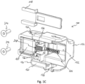
- the brake disc lock 100 further comprises an alarm device 110 which is arranged in a housing section 132 ( Fig. 1C ) of the brake disc lock 100.
- the alarm device 110 comprises a housing 134, an activation switch 112, a motion sensor (not shown), a control circuit (not shown) and an acoustic signal generator 113 ( Fig. 1B ).
- a cover 118 is designed to cover the open rear side of the lock body 114 and thus the locking mechanism 108 and the alarm device 110.
- Fig. 1C the cover 118 is shown removed from its original position.
- the brake disc lock 100 can be attached to a brake disc of a two-wheeler (not shown) in an open position of the claw 102 by inserting the hook structure 105 of the first claw section 104 into an opening in the brake disc in order to grip a section of the brake disc.
- the brake disc lock 100 is aligned in a plane parallel to the plane of extension of the brake disc, so that when the brake disc lock 100 is released, the brake disc is supported on a first support point 116 of the first claw section 104 and on a second support point 130 of the lock body 114.
- the brake disc lock 100 is locked and secured to the brake disc. This is done by moving the second claw portion 106 of the claw 102 toward the first claw portion 104 and the lock body 114, as will be explained in more detail below.
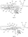
- Fig. 2A and Fig. 2B show a sectional view of parts of the brake disc lock 100 (without lock body 114) in a plan view in the closed position and in the open position, respectively.
- the claw sections 104, 106 are movable relative to each other between an open position and a closed position of the claw 102.
- the claw 102 has, in the closed position, Fig. 2A a predetermined clear width in order to encompass a section of a brake disc of a two-wheeler.
- the clear width of the claw 102 designates the inner dimension of the claw 102 in its closed position, i.e.
- the clear width of the claw 102 can generally also refer to the inner dimension or the distance between the ends of the two claw sections 104, 106.
- the first claw portion 104 of the claw 102 is fastened in an adjustable, fixed fastening position relative to the lock body 114 and thus relative to the locking mechanism 108 and the aforementioned rotary latch 202.
- An adjustment device 217 of the brake disc lock 100 is designed to be able to adapt the fastening position of the first claw portion 104 relative to the locking mechanism 108 to different brake discs.
- the adjustment device 217 can be designed such that it has an engagement contour in the form of a toothing 218 assigned to the lock body 114 or the locking mechanism 108, respectively, and a counter-engagement contour in the form of a counter-toothing 220 assigned to the first claw portion 104.
- the toothing 218 and the counter-toothing 220 can be brought into engagement with one another and secured to one another in various fastening positions.
- the toothing 218, which is assigned to the locking mechanism 108, can be attached to the side of the lock body 114 facing the first claw section 104.
- the counter-toothing 220, which is assigned to the first claw section 104, can be attached to the side of the first claw section 104 facing the lock body 114.
- the toothing 218 and the counter-toothing 220 can be secured to one another by a securing element, here embodied, for example, as two securing screws 214, in order to fix the fastening position of the first claw section 104.
- the adjustment device 217 is thus designed to adapt the predetermined clear width of the claw 102 to different brake discs.
- the locking screws 214 can be in the open position ( Fig. 2B ) of the claw 102 are loosened so that the mutual engagement of the teeth 218 and the counter-toothing 220 can be released.
- the clear width of the claw 102 can be adjusted to a desired position by moving the first claw section 104. Once the desired position is reached, the teeth 218 and the counter-teeth 220 can be re-engaged and secured to one another by means of the locking screws 214.
- Fig. 1C The two locking screws 214 are shown removed from their original position.
- the locking screws 214 are each inserted into a threaded bore 136 of the lock body 114 as soon as the toothing 218 and the counter-toothing 220 are engaged in the desired fastening position of the first claw section 104.
- the first claw section 104 and thus the counter-toothing 220 are pressed against the toothing 218 and secured against each other.
- the thus adjusted fastening position of the first claw portion 104 is a position which the first claw portion 104 assumes during the subsequent use of the brake disc lock 100 for repeated locking to the respective brake disc and release from the brake disc relative to the lock body 114 and thus relative to the locking mechanism 108 and maintains during use, thus in particular also during the movement of the claw 102 between the open position and the closed position.
- the rotary latch 202 which can be actuated by means of the locking cylinder 126, is designed to lock the claw 102 in the closed position ( Fig. 2A ).
- the rotary latch 202 is biased towards its locking position, for example by a torsion spring (not shown). In the illustration according to Fig. 2A and 2B the preload is directed counterclockwise.
- the rotary bolt 202 is rotatable on a surface 222 of the locking cylinder 126, wherein the rotational axis of the rotary latch 202 and the rotational axis of the locking cylinder 126 coincide.
- the rotary latch 202 has a tangential recess 208 on an outer cylindrical surface 222.
- the preloaded rotary latch 202 is temporarily pushed back toward a release position by a locking structure in the form of a locking protrusion 204 of the second claw section 106.
- the locking protrusion 204 engages a boundary of the tangential recess 208 of the rotary latch 202.
- the brake disc lock 100 comprises a return spring 206 in the form of a spiral spring, which is arranged between the second claw section 106 and the cover 118 is attached.
- the return spring 206 is pretensioned by moving the second claw section 106 in the direction of the first claw section 104.
- the brake disc lock 100 is unlocked by actuating the locking cylinder 126 using the associated key, the second claw section 106 is urged by the return spring 206 from the closed position into the open position of the claw 102.
- the alarm device 110 of the brake disc lock 100 can be activated by moving the claw 102 from the open position to the closed position and deactivated by moving the claw 102 from the closed position to the open position.
- an activation protrusion 216 of the second claw section 106 can actuate the activation switch 112 of the alarm device 110, designed as a contact switch, as soon as the claw 102 is moved from the open position to the closed position.
- the activation protrusion 216 can actuate the activation switch 112 directly or indirectly.
- the activation protrusion 216 can press a movable housing 134 of the alarm device 110 against the lock body 114 and thereby actuate the activation switch 112 of the alarm device 110. As long as the claw 102 is in the closed position, the alarm device 110 is activated.
- the second claw section 106 is pushed back into the open position of the claw 102 by the return spring 206.
- This can be done either - in the case of direct actuation - by releasing the activation protrusion 216 from the activation switch 112, or - in the case of the indirect actuation shown - by pushing back the second claw section 106 and thus the activation protrusion 216 into the open position of the claw 102, the housing 134 of the alarm device 110 can return to its original position. As a result, the housing 134 of the alarm device 110 is no longer pressed against the lock body 114, and the activation switch 112 is deactivated.
- the housing 134 of the alarm device 110 can be reset by a restoring force, which is generated, for example, by compressing a silicone layer between the housing 134 of the alarm device 110 and the lock body 114 due to the contact force of the activation protrusion 216.
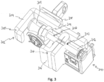
- Fig. 3 shows a perspective view of an alternative embodiment of a brake disc lock 100 with a first claw portion 304 and a second claw portion 306 of a claw 302; furthermore with a locking mechanism 308 and with an alarm device 310.
- the first claw portion 304 comprises a hook structure 305 and is firmly connected to the locking mechanism 308.
- the second claw portion 306 comprises a hook structure 307 at one end and a threaded rod 312 with a locking structure 309 at the other end, which forms a block-like thickening.
- the locking structure 309 of the second claw portion 306 can, in the shown closed position of the claw 302, similar to that in connection with Fig. 2A and 2B explained, can be locked by the locking mechanism 308.
Landscapes
- Engineering & Computer Science (AREA)
- Mechanical Engineering (AREA)
- Braking Arrangements (AREA)
Claims (15)
- Antivol pour disque de frein (100),comprenant une griffe (102, 302) ayant une première portion de griffe (104, 304) et une deuxième portion de griffe (106, 306) qui sont mobiles l'une par rapport à l'autre entre une position ouverte et une position fermée de la griffe (102, 302), la griffe (102, 302) ayant une largeur intérieure prédéterminée dans la position fermée pour s'engager autour d'une partie d'un disque de frein d'un deux-roues ; etcomprenant en outre un mécanisme de verrouillage (108, 308) conçu pour verrouiller la griffe (102, 302) dans la position fermée ;caractérisé parun dispositif de réglage (217, 317) conçu pour adapter la prédétermination de la largeur intérieure de la griffe (102, 302) à différents disques de frein, sachant que la prédétermination de la largeur intérieure de la griffe (102, 302) peut être adaptée au moyen du dispositif de réglage (217, 317) de telle sorte que la largeur intérieure, avec laquelle la griffe (102, 302) délimite efficacement un espace de réception pour le disque de frein dans la position fermée, est prédéterminée pour une fixation et un verrouillage répétés ultérieurs de l'antivol pour disque de frein (100) sur le disque de frein.
- Antivol pour disque de frein (100) selon la revendication 1,dans lequel le mécanisme de verrouillage (108, 308) est relié solidairement à la première portion de griffe (104 ; 304), la deuxième portion de griffe (106, 306) étant mobile par rapport à la première portion de griffe (104, 304) et au mécanisme de verrouillage (108, 308) ;
et/oul'antivol pour de disque de frein (100) comprend un corps d'antivol (114) dans lequel le mécanisme de verrouillage (108, 308) est retenu et sur lequel la deuxième portion de griffe (106, 306) est guidée de manière mobile ; et/oula première portion de griffe (104, 304) et la deuxième portion de griffe (106, 306) sont mobiles linéairement l'une par rapport à l'autre entre la position ouverte et la position fermée. - Antivol pour disque de frein (100) selon l'une des revendications précédentes,dans lequel l'une au moins des portions de griffe (104, 106, 304, 306) comprend une structure de crochet (105, 107, 305, 307) qui est conçue pour s'engager autour de ladite partie du disque de frein et qui se trouve à une distance effective du mécanisme de verrouillage (108, 308) lorsque la griffe (102, 302) est fermée et verrouillée,le dispositif de réglage (217, 317) est conçu pour adapter la distance effective de la structure de crochet (105, 107, 305, 307) par rapport au mécanisme de verrouillage (108, 308).
- Antivol pour disque de frein (100) selon l'une des revendications précédentes,
dans lequel, dans un état d'utilisation de l'antivol pour disque de frein (100), la première portion de griffe (104, 304) est fixée dans une position de fixation fixe adaptable par rapport au mécanisme de verrouillage (108, 308), le dispositif de réglage (217, 317) étant conçu pour adapter la position de fixation de la première portion de griffe (104, 304) par rapport au mécanisme de verrouillage (108, 308). - Antivol pour disque de frein (100) selon la revendication 4,dans lequel l'antivol pour disque de frein (100) comprend un support portant le mécanisme de verrouillage (108, 308), la première portion de griffe (104, 304) étant fixée au support ;
et/oule dispositif de réglage (217, 317) présente un contour d'engagement (218) associé au mécanisme de verrouillage (108, 308) et un contre-contour d'engagement (220) associé à la première portion de griffe (104, 304), le contour d'engagement (218) et le contre-contour d'engagement (220) pouvant être mis en prise l'un avec l'autre dans différentes positions de fixation et pouvant être bloqués l'un à l'autre dans la position de fixation respective ; et/oula première portion de griffe (104, 304) est rigide et/ou présente une longueur fixe. - Antivol pour disque de frein (100) selon la revendication 3,dans lequel ladite au moins une portion de griffe (104, 106, 304, 306) comprend une structure de verrouillage (309) avec laquelle le mécanisme de verrouillage (108, 308) est en prise lorsque la griffe (102, 302) est fermée et verrouillée, le dispositif de réglage (217, 317) étant conçu pour adapter une longueur effective entre la structure de crochet (105, 107, 305, 307) et la structure de verrouillage (309) de ladite au moins une portion de griffe (104, 106, 304, 306) ;
oul'antivol pour disque de frein (100) comprend un support portant le mécanisme de verrouillage (108, 308), ladite au moins une portion de griffe (104, 106, 304, 306) ayant une extrémité de liaison à laquelle ladite au moins une portion de griffe (104, 106, 304, 306) est reliée au support dans une position invariable, le dispositif de réglage (217, 317) étant conçu pour adapter une longueur effective entre la structure de crochet (105, 107, 305, 307) et l'extrémité de liaison de ladite au moins une portion de griffe (104, 106, 304, 306). - Antivol pour disque de frein (100) selon la revendication 6,
dans lequel le dispositif de réglage (217, 317) comprend une tige filetée (312) et un taraudage (313) déplaçable le long de la tige filetée (312), grâce auxquels la longueur effective de ladite au moins une portion de griffe (104, 106, 304, 306) peut être adaptée. - Antivol pour disque de frein (100) selon l'une des revendications précédentes,
dans lequel le dispositif de réglage (217, 317) ne peut être actionné qu'en réponse à un déverrouillage du mécanisme de verrouillage (108, 308) afin d'adapter la largeur intérieure prédéterminée de la griffe (102, 302) à différents disques de frein. - Antivol pour disque de frein (100) selon l'une des revendications précédentes,dans lequel le dispositif de réglage (217, 317) comprend un élément de blocage (314) conçu pour bloquer un réglage de la largeur intérieure prédéterminée de la griffe (102, 302), l'élément de blocage (314) étant masqué par le disque de frein ou par une partie de l'antivol pour disque de frein (100) et/ou l'élément de blocage (314) étant arrêté à l'encontre d'un mouvement lorsque l'antivol pour disque de frein (100) est monté sur le disque de frein et lorsque la griffe (102, 302) est fermée et verrouillée ;
et/oula griffe (102, 302) est précontrainte en direction de la position ouverte. - Antivol pour disque de frein (100) selon l'une des revendications précédentes,
dans lequel le mécanisme de verrouillage (108, 308) comprend un verrou qui, dans une position de verrouillage - lorsque la griffe (102, 302) est fermée - verrouille la deuxième portion de griffe (106, 306) sur la première portion de griffe (104, 304) et, dans une position de libération, libère la deuxième portion de griffe (106, 306) pour un mouvement par rapport à la première portion de griffe (104, 304). - Antivol pour disque de frein (100) selon la revendication 10,dans lequel le verrou est précontraint en direction de la position de verrouillage, le verrou étant conçu pour être repoussé d'abord en direction de la position de libération par le déplacement de la griffe (102, 302) de la position ouverte à la position fermée, puis pour s'encliqueter dans la position de verrouillage en raison de la précontrainte ;
et/oule verrou est monté mobile en rotation et présente une surface enveloppe (222) ayant un évidement tangentiel (208), l'évidement tangentiel (208) libérant, dans la position de libération du verrou, une bosse de verrouillage (204) de la deuxième portion de griffe (106, 306). - Antivol pour disque de frein (100) selon l'une des revendications précédentes,
dans lequel l'une au moins des portions de griffe (104, 106, 304, 306) est conçue pour s'engager dans une ouverture du disque de frein et pour ainsi maintenir l'antivol pour disque de frein (100) suspendu au disque de frein. - Antivol pour disque de frein (100) selon l'une des revendications précédentes,
dans lequel l'antivol pour disque de frein (100) comprend un dispositif d'alarme (110, 310) pour émettre un signal d'alarme, le dispositif d'alarme (110, 310) étant conçu pour être activé par un déplacement de la griffe (102, 302) vers la position fermée et pour être désactivé par un déplacement de la griffe (102, 302) de la position fermée vers la position ouverte. - Antivol pour disque de frein (100) selon la revendication 13,dans lequel le dispositif d'alarme (110, 310) comprend un commutateur d'activation (112) conçu pour être actionné automatiquement, dans la position fermée, par la deuxième portion de griffe (106, 306) ou par une partie de l'antivol pour disque de frein (100) reliée à la deuxième portion de griffe (106, 306) ;
et/oule dispositif d'alarme (110, 310) est disposé dans une partie de boîtier (132) de l'antivol pour disque de frein (100) qui est reliée solidairement à la première portion de griffe (104, 304), le dispositif d'alarme (110, 310) n'étant accessible que suite à un déverrouillage du mécanisme de verrouillage (108, 308). - Antivol pour disque de frein (100) selon l'une des revendications précédentes,
dans lequel l'antivol pour disque de frein (100) comprend une première partie de blocage (120) associée à la première portion de griffe (104, 304) et une deuxième partie de blocage (122) associée à la deuxième portion de griffe (106, 306), la première partie de blocage (120) et la deuxième partie de blocage (122) formant, en position ouverte de la griffe (102, 302), une ouverture de réception (123) pour insérer un œillet d'une pièce de blocage flexible (124), en particulier d'une chaîne, et la première partie de blocage (120) et la deuxième partie de blocage (122) formant, dans la position fermée de la griffe (102, 302), une délimitation fermée sur le pourtour de l'ouverture de réception (123), afin de bloquer l'œillet inséré sur l'antivol pour disque de frein (100).
Applications Claiming Priority (1)
| Application Number | Priority Date | Filing Date | Title |
|---|---|---|---|
| DE102021115329.8A DE102021115329A1 (de) | 2021-06-14 | 2021-06-14 | Bremsscheibenschloss |
Publications (3)
| Publication Number | Publication Date |
|---|---|
| EP4105111A1 EP4105111A1 (fr) | 2022-12-21 |
| EP4105111B1 true EP4105111B1 (fr) | 2025-07-02 |
| EP4105111C0 EP4105111C0 (fr) | 2025-07-02 |
Family
ID=81854677
Family Applications (1)
| Application Number | Title | Priority Date | Filing Date |
|---|---|---|---|
| EP22176500.1A Active EP4105111B1 (fr) | 2021-06-14 | 2022-05-31 | Dispositif de blocage de disques de frein |
Country Status (5)
| Country | Link |
|---|---|
| US (1) | US12337917B2 (fr) |
| EP (1) | EP4105111B1 (fr) |
| CN (1) | CN115476946A (fr) |
| DE (1) | DE102021115329A1 (fr) |
| TW (1) | TW202313393A (fr) |
Family Cites Families (13)
| Publication number | Priority date | Publication date | Assignee | Title |
|---|---|---|---|---|
| DE4323693C2 (de) | 1993-07-15 | 2002-07-18 | Bremicker Soehne Kg A | Hangschloß |
| JPH08156857A (ja) * | 1994-12-07 | 1996-06-18 | I I C:Kk | 自動二輪車用盗難防止装置 |
| DE29500444U1 (de) | 1995-01-12 | 1995-02-23 | Shieh, Jin-Ren, Taichung | Motorrad-Scheibenbremsen-Schloß |
| DE10250961A1 (de) | 2002-11-01 | 2004-05-13 | ABUS August Bremicker Söhne KG | Rahmenschloss |
| DE102005043926A1 (de) | 2005-09-14 | 2007-03-29 | ABUS August Bremicker Söhne KG | Bremsscheibenschloss |
| GB2451075B (en) * | 2007-07-16 | 2012-04-11 | Ivan Foti | Disc brake locks |
| DE102007058550A1 (de) * | 2007-12-05 | 2009-06-10 | ABUS August Bremicker Söhne KG | Bremsscheibenschloss |
| DE102007058551A1 (de) | 2007-12-05 | 2009-06-10 | ABUS August Bremicker Söhne KG | Bremsscheibenschloss |
| DE102009030031A1 (de) | 2009-06-23 | 2010-12-30 | ABUS August Bremicker Söhne KG | Bügelschloss |
| DE102011113771A1 (de) | 2011-09-19 | 2013-03-21 | ABUS August Bremicker Söhne KG | Schlaufenschloss |
| DE102015103170A1 (de) | 2015-03-04 | 2016-09-08 | ABUS August Bremicker Söhne KG | Rahmenschloss |
| DE102018111305A1 (de) | 2018-05-11 | 2019-11-14 | ABUS August Bremicker Söhne KG | Bügelschloss |
| DE102018111287A1 (de) * | 2018-05-11 | 2019-11-14 | ABUS August Bremicker Söhne KG | Bremsscheibenschloss |
-
2021
- 2021-06-14 DE DE102021115329.8A patent/DE102021115329A1/de active Pending
-
2022
- 2022-05-31 EP EP22176500.1A patent/EP4105111B1/fr active Active
- 2022-06-07 CN CN202210637335.9A patent/CN115476946A/zh active Pending
- 2022-06-08 US US17/835,054 patent/US12337917B2/en active Active
- 2022-06-13 TW TW111121855A patent/TW202313393A/zh unknown
Also Published As
| Publication number | Publication date |
|---|---|
| CN115476946A (zh) | 2022-12-16 |
| DE102021115329A1 (de) | 2022-12-15 |
| TW202313393A (zh) | 2023-04-01 |
| US20220396325A1 (en) | 2022-12-15 |
| US12337917B2 (en) | 2025-06-24 |
| EP4105111C0 (fr) | 2025-07-02 |
| EP4105111A1 (fr) | 2022-12-21 |
Similar Documents
| Publication | Publication Date | Title |
|---|---|---|
| EP2019178B1 (fr) | Serrure à barres articulées | |
| DE102010025355B4 (de) | Schlossvorrichtung für ein Kraftfahrzeug | |
| EP2267256B1 (fr) | Cadenas | |
| EP3575520B1 (fr) | Cadenas à arceau | |
| EP3064419B1 (fr) | Antivol de cadre | |
| EP3566933B1 (fr) | Chaîne de liaison et système de verrouillage du cadre pour un véhicule à deux roues | |
| EP1760230B1 (fr) | Serrure | |
| DE60317737T2 (de) | Verriegelbares Schaltwerk | |
| DE102010008054B4 (de) | Zweirad-Schloss | |
| DE102007058550A1 (de) | Bremsscheibenschloss | |
| DE102008012994A1 (de) | Hangschloss | |
| EP1077174A2 (fr) | Serrure pour frein à disque | |
| DE202014006369U1 (de) | Ringbügelschloss | |
| DE102021114205B4 (de) | Rahmenschloss | |
| DE3126751C2 (de) | Vorrichtung zum Neueinstellen des Schlüsselgeheimnisses in einem Permutationsschloß für Koffer oder dergleichen | |
| DE10335311B4 (de) | Lenkschlossvorrichtung | |
| EP4105111B1 (fr) | Dispositif de blocage de disques de frein | |
| EP2993090B2 (fr) | Verrouillage de volant de direction | |
| WO1992021551A1 (fr) | Moyeu a serrage rapide pour bicyclettes | |
| DE102009053563A1 (de) | Lenkradschloss | |
| EP0520154A1 (fr) | Dispositif de fixation d'un câble sur un cadre de bicyclette | |
| DE69401367T2 (de) | Diebstahlsicherung für ein Fahrzeug | |
| EP3296164A1 (fr) | Dispositif sécurisé de fermeture d'un composant essentiellement fonctionnel du véhicule automobile | |
| DE102025110908B3 (de) | Rahmenschloss für ein Fahrrad | |
| EP4303107B1 (fr) | Dispositif de rangement |
Legal Events
| Date | Code | Title | Description |
|---|---|---|---|
| PUAI | Public reference made under article 153(3) epc to a published international application that has entered the european phase |
Free format text: ORIGINAL CODE: 0009012 |
|
| STAA | Information on the status of an ep patent application or granted ep patent |
Free format text: STATUS: THE APPLICATION HAS BEEN PUBLISHED |
|
| AK | Designated contracting states |
Kind code of ref document: A1 Designated state(s): AL AT BE BG CH CY CZ DE DK EE ES FI FR GB GR HR HU IE IS IT LI LT LU LV MC MK MT NL NO PL PT RO RS SE SI SK SM TR |
|
| STAA | Information on the status of an ep patent application or granted ep patent |
Free format text: STATUS: REQUEST FOR EXAMINATION WAS MADE |
|
| 17P | Request for examination filed |
Effective date: 20230206 |
|
| RBV | Designated contracting states (corrected) |
Designated state(s): AL AT BE BG CH CY CZ DE DK EE ES FI FR GB GR HR HU IE IS IT LI LT LU LV MC MK MT NL NO PL PT RO RS SE SI SK SM TR |
|
| STAA | Information on the status of an ep patent application or granted ep patent |
Free format text: STATUS: EXAMINATION IS IN PROGRESS |
|
| 17Q | First examination report despatched |
Effective date: 20230403 |
|
| GRAP | Despatch of communication of intention to grant a patent |
Free format text: ORIGINAL CODE: EPIDOSNIGR1 |
|
| STAA | Information on the status of an ep patent application or granted ep patent |
Free format text: STATUS: GRANT OF PATENT IS INTENDED |
|
| INTG | Intention to grant announced |
Effective date: 20250205 |
|
| GRAS | Grant fee paid |
Free format text: ORIGINAL CODE: EPIDOSNIGR3 |
|
| GRAA | (expected) grant |
Free format text: ORIGINAL CODE: 0009210 |
|
| STAA | Information on the status of an ep patent application or granted ep patent |
Free format text: STATUS: THE PATENT HAS BEEN GRANTED |
|
| AK | Designated contracting states |
Kind code of ref document: B1 Designated state(s): AL AT BE BG CH CY CZ DE DK EE ES FI FR GB GR HR HU IE IS IT LI LT LU LV MC MK MT NL NO PL PT RO RS SE SI SK SM TR |
|
| REG | Reference to a national code |
Ref country code: GB Ref legal event code: FG4D Free format text: NOT ENGLISH |
|
| REG | Reference to a national code |
Ref country code: CH Ref legal event code: EP |
|
| REG | Reference to a national code |
Ref country code: IE Ref legal event code: FG4D Free format text: LANGUAGE OF EP DOCUMENT: GERMAN |
|
| U01 | Request for unitary effect filed |
Effective date: 20250702 |
|
| U07 | Unitary effect registered |
Designated state(s): AT BE BG DE DK EE FI FR IT LT LU LV MT NL PT RO SE SI Effective date: 20250708 |
|
| PG25 | Lapsed in a contracting state [announced via postgrant information from national office to epo] |
Ref country code: IS Free format text: LAPSE BECAUSE OF FAILURE TO SUBMIT A TRANSLATION OF THE DESCRIPTION OR TO PAY THE FEE WITHIN THE PRESCRIBED TIME-LIMIT Effective date: 20251102 |
|
| PG25 | Lapsed in a contracting state [announced via postgrant information from national office to epo] |
Ref country code: NO Free format text: LAPSE BECAUSE OF FAILURE TO SUBMIT A TRANSLATION OF THE DESCRIPTION OR TO PAY THE FEE WITHIN THE PRESCRIBED TIME-LIMIT Effective date: 20251002 |
|
| PG25 | Lapsed in a contracting state [announced via postgrant information from national office to epo] |
Ref country code: HR Free format text: LAPSE BECAUSE OF FAILURE TO SUBMIT A TRANSLATION OF THE DESCRIPTION OR TO PAY THE FEE WITHIN THE PRESCRIBED TIME-LIMIT Effective date: 20250702 |
|
| PG25 | Lapsed in a contracting state [announced via postgrant information from national office to epo] |
Ref country code: CZ Free format text: LAPSE BECAUSE OF FAILURE TO SUBMIT A TRANSLATION OF THE DESCRIPTION OR TO PAY THE FEE WITHIN THE PRESCRIBED TIME-LIMIT Effective date: 20250702 |
|
| PG25 | Lapsed in a contracting state [announced via postgrant information from national office to epo] |
Ref country code: PL Free format text: LAPSE BECAUSE OF FAILURE TO SUBMIT A TRANSLATION OF THE DESCRIPTION OR TO PAY THE FEE WITHIN THE PRESCRIBED TIME-LIMIT Effective date: 20250702 |
|
| PG25 | Lapsed in a contracting state [announced via postgrant information from national office to epo] |
Ref country code: RS Free format text: LAPSE BECAUSE OF FAILURE TO SUBMIT A TRANSLATION OF THE DESCRIPTION OR TO PAY THE FEE WITHIN THE PRESCRIBED TIME-LIMIT Effective date: 20251002 |
|
| PG25 | Lapsed in a contracting state [announced via postgrant information from national office to epo] |
Ref country code: ES Free format text: LAPSE BECAUSE OF FAILURE TO SUBMIT A TRANSLATION OF THE DESCRIPTION OR TO PAY THE FEE WITHIN THE PRESCRIBED TIME-LIMIT Effective date: 20250702 |
|
| PG25 | Lapsed in a contracting state [announced via postgrant information from national office to epo] |
Ref country code: SM Free format text: LAPSE BECAUSE OF FAILURE TO SUBMIT A TRANSLATION OF THE DESCRIPTION OR TO PAY THE FEE WITHIN THE PRESCRIBED TIME-LIMIT Effective date: 20250702 |
|
| PG25 | Lapsed in a contracting state [announced via postgrant information from national office to epo] |
Ref country code: SK Free format text: LAPSE BECAUSE OF FAILURE TO SUBMIT A TRANSLATION OF THE DESCRIPTION OR TO PAY THE FEE WITHIN THE PRESCRIBED TIME-LIMIT Effective date: 20250702 |