EP4105151B1 - Transporteur à bande charnière pourvu d' illets de charnière pouvant être positionnés - Google Patents
Transporteur à bande charnière pourvu d' illets de charnière pouvant être positionnés Download PDFInfo
- Publication number
- EP4105151B1 EP4105151B1 EP22175420.3A EP22175420A EP4105151B1 EP 4105151 B1 EP4105151 B1 EP 4105151B1 EP 22175420 A EP22175420 A EP 22175420A EP 4105151 B1 EP4105151 B1 EP 4105151B1
- Authority
- EP
- European Patent Office
- Prior art keywords
- hinge
- link
- belt conveyor
- hinged belt
- plate
- Prior art date
- Legal status (The legal status is an assumption and is not a legal conclusion. Google has not performed a legal analysis and makes no representation as to the accuracy of the status listed.)
- Active
Links
Images


Classifications
-
- B—PERFORMING OPERATIONS; TRANSPORTING
- B65—CONVEYING; PACKING; STORING; HANDLING THIN OR FILAMENTARY MATERIAL
- B65G—TRANSPORT OR STORAGE DEVICES, e.g. CONVEYORS FOR LOADING OR TIPPING, SHOP CONVEYOR SYSTEMS OR PNEUMATIC TUBE CONVEYORS
- B65G17/00—Conveyors having an endless traction element, e.g. a chain, transmitting movement to a continuous or substantially-continuous load-carrying surface or to a series of individual load-carriers; Endless-chain conveyors in which the chains form the load-carrying surface
- B65G17/06—Conveyors having an endless traction element, e.g. a chain, transmitting movement to a continuous or substantially-continuous load-carrying surface or to a series of individual load-carriers; Endless-chain conveyors in which the chains form the load-carrying surface having a load-carrying surface formed by a series of interconnected, e.g. longitudinal, links, plates, or platforms
- B65G17/08—Conveyors having an endless traction element, e.g. a chain, transmitting movement to a continuous or substantially-continuous load-carrying surface or to a series of individual load-carriers; Endless-chain conveyors in which the chains form the load-carrying surface having a load-carrying surface formed by a series of interconnected, e.g. longitudinal, links, plates, or platforms the surface being formed by the traction element
-
- B—PERFORMING OPERATIONS; TRANSPORTING
- B65—CONVEYING; PACKING; STORING; HANDLING THIN OR FILAMENTARY MATERIAL
- B65G—TRANSPORT OR STORAGE DEVICES, e.g. CONVEYORS FOR LOADING OR TIPPING, SHOP CONVEYOR SYSTEMS OR PNEUMATIC TUBE CONVEYORS
- B65G17/00—Conveyors having an endless traction element, e.g. a chain, transmitting movement to a continuous or substantially-continuous load-carrying surface or to a series of individual load-carriers; Endless-chain conveyors in which the chains form the load-carrying surface
- B65G17/30—Details; Auxiliary devices
- B65G17/38—Chains or like traction elements; Connections between traction elements and load-carriers
- B65G17/40—Chains acting as load-carriers
Definitions
- the subject matter of the invention relates to a hinged belt conveyor with an endless hinged belt, wherein the hinged belt is formed by links that are connected to one another in an articulated manner. Each link has hinge eyes that are arranged offset from one another.
- Hinged belt conveyors are mainly used in conjunction with machine tools. Hinged belt conveyors can be used as individual conveyors on machine tools or as linked conveyor systems.
- a hinged belt conveyor can be used to dispose of chips, slugs or nipples produced by the machine tool.
- a hinged belt conveyor is part of a chip disposal and raw material recovery system.
- the hinged belt conveyor has a hinged belt which is connected to a drive device.
- the endlessly rotating hinged belt transports away leftover raw materials.
- the links forming the hinged belt are made of metal.
- the publication DE 202 006 001 016 U1 A hinge band is known in which the links are made of metal.
- a link comprises a plate to which hinge eyes are welded.
- a link of a hinge band is made from a sheet metal part. First, a plate with tabs is formed, and then the hinge eyes are formed by roll forming the tabs.
- the individual links are arranged in such a way that a bolt is passed through the hinge eyes of two adjacent links.
- the bolts have end areas that are connected to a hollow bolt chain.
- the problem is that this material can get into the gap between the hinge eyes. If the hinged belt has two deflection areas, the links must be pivoted against each other in the deflection areas. The pivoting process is made more difficult by the punching waste or similar located in the gaps between the hinge eyes, thus impairing the functionality of the hinged belt conveyor.
- a hinge band which is formed by links.
- the individual links are made up of several parts.
- Each link has a profile rail which is connected to driver elements in a locking manner.
- the driver elements have hinge eyes through which an axis extends.
- belt conveyors are used as an alternative to a hinged belt conveyor.
- the hinged belt is replaced by a belt.
- This type of belt is made of plastic.
- the temperature resistance is often limited. If, for example, hot chips fall onto the belt, the surface of the belt can be damaged.
- Another problem with this type of belt is that the deflection pulleys around which the belt runs must be aligned very precisely.
- the length-width ratio of a strap is unfavorable, it is very difficult to keep the strap in position. It may also be necessary to provide a flat support on which the strap runs at least partially.
- the present invention is based on the objective of providing a hinge belt conveyor whose hinge belt is subject to less wear.
- the hinged belt conveyor according to the invention has a continuously rotating hinged belt.
- the hinged belt is moved by means of a drive device.
- the hinged belt is formed by links that are connected to one another in an articulated manner.
- Each link has hinge eyes that are offset from one another.
- the hinge eyes are connected to the link in a form-fitting manner.
- This design of a hinged belt conveyor according to the invention enables significantly tighter manufacturing tolerances to be achieved. Because the manufacturing tolerances of the link and the hinge eyes are smaller, the gaps between the eyes of adjacent links are also reduced in width, so that the area of use and application of the hinged belt conveyor according to the invention can be expanded.
- a hinged belt conveyor designed in this way can therefore also replace a belt conveyor, for example, when it comes to transporting small chips or small raw material residues.
- the link and the hinge eyes are designed as separate components, they can also be made from different materials. This means that the link can be adapted to the transport task.
- the link can, for example, be made from a high-temperature-resistant material. Alternatively, it can also be made from metal, plastic, aluminum or another material.
- the hinge eyes can also be adjusted to the axis. Since a swivel movement takes place between the hinge eyes and the respective axis, the hinge eye can have a bushing made of a material that is adapted to the material of the axle.
- the bushing can be made of a brass alloy.
- the hinged belt conveyor according to the invention is also characterized in that receptacles are provided in each longitudinal region of a link and each hinge eye has an extension with a geometric structure complementary to the receptacle.
- the longitudinal region of the link is to be understood as an extension of the link transverse to the transport direction of the hinged belt.
- the receptacle preferably extends over the entire length of the link.
- the hinge eyes of two adjacent links are positioned relative to one another along the axis by suitable measures so that a minimal gap is created between adjacent hinge eyes of the two adjacent links. This makes it possible to reduce the gap width between the hinge eyes of two adjacent links to the necessary level.
- the hinge eyes are fixed in their position. The advantage of such a design of the hinge belt conveyor can also be seen in the fact that manufacturing tolerances of the link and the hinge eyes can be further compensated.
- the receptacles extending in the longitudinal direction of the link are preferably formed by a groove.
- the link can be manufactured in the form of a profile as a semi-finished product that already has the necessary groove.
- a link is provided by cutting the semi-finished product to the appropriate length.
- the advantage of such a design can also be seen in the fact that the stiffness of the hinge belt can be influenced by varying the number of hinge eyes.
- Another advantage of the hinge belt conveyor according to the invention is that the production of a hinged belt conveyor with different widths of the hinged belt can be achieved more easily.
- each longitudinal region of the link has a recess into which the hinge eyes partially protrude.
- the hinge eyes have a substantially circular cross-section below the extension.
- the recesses in the longitudinal regions have a circular arc shape that is adapted to the external shape of the hinge eyes.
- the hinge band has a substantially flat support surface in a stretched position. This achieves, in particular, an even distribution of the raw material residues that hit the hinge band.
- At least some links have at least one support element connected to the underside of the respective link.
- the support element is preferably located on a corresponding rail, so that sagging of the link belt is avoided. Furthermore, the load on the positive connections between the hinge eyes and the links is at least reduced.
- the at least one support element and/or the at least one storage element is connected to the top or bottom side. It is proposed that the top and/or bottom side have a groove into which such a support element or storage element can be introduced.
- the connection can be positive and/or non-positive.
- the link can be made from a profile. To increase rigidity, it is advantageous if the link is formed from two plates spaced apart from one another.
- the plates can be connected to one another by pressing or screwing, for example. It is also possible for the extensions of the hinge eyes and the corresponding recesses in the plates to be designed in such a way that the plates are connected to one another by means of the hinge eyes. It is not essential that the plates are made from the same material.
- an upper plate that forms the top of the hinge band can be made from a different material than the plate that lies opposite this plate.
- the plate that forms the underside can take on the function of stiffening the links.
- the plate can have corresponding longitudinal ribs that serve to support the upper plate.
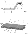
- Fig. 1 shows a schematic side view of a hinged belt conveyor 1.
- the hinged belt conveyor has a substantially horizontally arranged feed area 2.
- the feed area 2 merges into an incline area 3.
- the incline angle is provided with the reference symbol ⁇ .
- the incline area 3 merges into a substantially horizontal discharge area 4.
- the incline area 3 and the discharge area 4 are held by a frame 5.
- the hinge belt 7 has an upper run 8 and a lower run 9.
- the reference number 10 designates a deflection area in the feed area 2.
- a corresponding deflection area 11 is provided in the discharge area 4.
- a drive device 12 is arranged in the deflection area 11.
- the drive device 12 is an electric motor which is directly or indirectly connected to a drive wheel for driving the hinged belt conveyor.
- the Fig. 1 The design of the hinged belt conveyor 1 shown is an example.
- the hinged belt conveyor can have a straight design or a straight and rising design.
- Parts not shown, such as chips, are fed onto the hinge belt 7 in the feed area 2.
- the chips or, more generally, raw material residues are conveyed to the discharge area 4, from where they are discharged, for example, into a raw material container not shown.
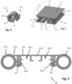
- each link 13 comprises a plate 14 and hinge eyes 15.1, 15.2.
- the hinge eyes 15.1, 15.2 are arranged on the longitudinal edges of the plates 14.
- the longitudinal edges of the plates 14 extend transversely to the transport direction of the hinge band conveyor.
- the hinge eyes 15.1, 15.2 are arranged offset from one another, so that when two adjacent links are connected, the hinge eyes 15.1, 15.2 alternate with one another.
- a hinge eye 15.1 is shown enlarged.
- the hinge eyes 15.1, 15.2 are preferably designed identically, so that only one form or shape of hinge eyes is sufficient to form the hinge band.
- An extension 19 is formed on the outer surface of the base body 16.
- the extension 19 has a substantially T-shaped cross section.
- the extension 19 extends in the longitudinal direction of the hinge eye 15.1.
- the plate 14 has a receptacle 24.1, 24.2 in each of its opposite longitudinal regions 23.1, 23.2.
- the receptacle has a substantially T-shaped cross section.
- the hinge eye 15.1 or 15.2 has an extension 19 which has a geometric structure that is complementary to the receptacle 23.1 or 23.2.
- the receptacles 24.1, 24.2 are geometrically identical.
- the hinge eyes are preferably made from a profile that already has the corresponding inner and outer contours.
- the corresponding number of hinge eyes required for the manufacture of the hinge band can also be provided by cutting or cutting the profile to length.
- Fig. 5 shows a second embodiment of a member 13.
- the member 13 according to Fig. 5 is formed by a plate 14.1.
- the plate 14.1 is preferably designed as an extrusion profile.
- the plate 14.1 has a top side 20 which is essentially flat.
- the plate 14.1 has a receptacle 24.1, 24.2 on each of its opposite longitudinal regions 23.1, 23.2.
- the receptacle has an essentially T-shaped cross-section. according to the presentation Fig. 5
- hinge eyes 15.1 and 15.2 each have an extension 19, each extension having a geometric structure that is complementary to the receptacle 24.1 and 24.2.
- the connection can be designed, for example, in the form of a snap connection.
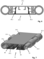
- the plate 14.1 has ribs 35.1, 35.2 extending in the longitudinal direction.
- the end areas, i.e. the free areas of the ribs 25.1, 25.2, are designed in the shape of a hook. From the Fig. 6 it is evident that the plate 14.2 has corresponding connecting ribs 36.1, 36.2.
- a removable variant of a link enables a modular construction of a hinge belt.
- a link according to Fig. 5 If there is a need to absorb increased forces and thus meet higher strength requirements, the link can be Fig. 5 be stiffened by the additional plate 14.2.
- the plate 14.1 has ribs 35.1, 35.2.
- the plate 14.2 has corresponding connecting ribs 36.1, 36.2.
- the connection of the ribs 35.1, 35.2 with the connecting ribs 36.1, 36.2 is enlarged in the Fig. 8 shown. From the enlarged view it can be seen that the ribs 35.1, 35.2 are essentially hook-shaped at their free end areas with the connecting ribs 36.1, 36.2, so that a positive and/or non-positive connection can be made between the plates 14.1, 14.2.
- the ribs 35.1, 35.2 and possibly the connecting ribs 36.1, 36.2 have a certain flexibility transversely to the longitudinal direction of the plates, so that in particular a snap connection is created.
- both the plate 14.1 and the plate 14.2 each have a lip 39.1, 39.2 in the receiving area 24.2.
- the lips 39.1, 39.2 extend over part of the thickness of the plate 14.1. They have an outer contour that is adapted to the outer geometry of the hinge eyes 15.1, 15.2.
- the lips 39.1, 39.2 are subject to a certain amount of wear during operation of the hinge band. They can be referred to as wear indicators. If the lips 39.1, 39.2 are worn, it is advisable to replace at least the corresponding links of the hinge band.
- both the plate 14.1 and the plate 14.2 each have an extension 40.1 and 40.2 which delimit a receptacle 41 which is essentially circular in cross section.
- a receptacle 41 which is essentially circular in cross section.
- the screws 39 shown are screwed in, thereby further securing the connection between the plates 14.1 and 14.2.
- the extension 40.2 has a rib 42 in its free end area that extends in the longitudinal direction of the extension and that forms a positive and/or non-positive connection with a web 43 that is formed on the plate 14.1.
- the web 43 simultaneously forms an abutment for the extension 40.2, so that when a screw is screwed into the receptacle 40, the extension 40.2 remains stationary.
- the hinge eye 15.2 has an extension 19 which is essentially T-shaped.
- the extension has inclined surfaces 44.1, 44.2 which interact with correspondingly inclined surfaces 45.1 of the plate 14.1 and 45.2 of the plate 14.2. This achieves a certain tension of the hinge eye 15.2 so that the outer surface of the hinge eyes 15.2 rests against the lips 39.1, 39.2.
- the Fig. 9 shows the right side of the penis Fig. 7
- the left side of the limb is designed accordingly.
- Fig. 10 shows a section of a hinged belt conveyor consisting of links 13 according to Fig. 7
- the description of the members in connection with the Fig. 7 , 8 and 9 From the Fig. 10 bolts 37 are partially visible, which extend through the hinge eyes 15.1, 15.2.
- each link 13 has a stop plate 44 on its respective short side, which is screwed to the respective link 13 by means of the screws 38.
- the stop plates 44 have stop surfaces 45.1, 45.2, which limit a pivoting angle ⁇ of adjacent links 13.
- FIG. 11 Another example of a hinged belt conveyor is shown.
- the basic structure of the hinged belt in the Fig. 11 essentially corresponds to the structure of the hinge band according to Fig. 1 . Identical parts are provided with the same reference numerals.
- the description of the hinge band according to the Fig. 1-4 is based on the embodiment according to Fig. 11 essentially transferable. The following describes the differences between the embodiment according to Fig. 1-4 and the Fig. 11 explained.
- the member 13 is formed by two plates 14.1, 14.2.
- the plates 14.1, 14.2 are connected to each other in a form-fitting and force-fitting manner.
- the plate 14.1 forms the upper side 20. From the illustration according to Fig. 11 it can be seen that the plate 14.1 has grooves 22.1-22.3.
- the grooves 22.1-22.3 run transversely to the transport direction of the link belt.
- the grooves 22.1-22-3 are parallel to one another in the embodiment shown. They are at the same distance from one another.
- the grooves 22.1 and 22.2 are adjacent to the longitudinal region 23.1 and 23.2.
- a storage element 26.1 and 26.2 is arranged in the groove 22.1 and the groove 22.2.
- the plates 14.1, 14.2 are made from a preferably extruded profile. The profile is deflected accordingly. By rotating a plate, these can be put together to form a link.
- the plates 14.1, 14.2 are preferably connected to one another in a form-fitting and/or force-fitting manner.
- FIG. 11 From the illustration Fig. 11 it is evident that support elements 27 are arranged in the groove 22.3 of the plate 14.2.
- the geometry of the groove 22.3 corresponds to the geometry of the receptacle 24.1.
- the support elements 27 correspond geometrically to the hinge eyes 15.1, 15.2.
- This A link belt can be made from two parts. It should also be noted at this point that both the Fig. 11 and in the following Fig. 12-1, for the sake of clarity, not all hinge eyes 15.1, 15.2 are shown.
- Fig. 12 shows another embodiment of a link belt 1.
- the design of the link belt 1 according to Fig. 12 essentially corresponds to the design of the link belt according to Fig. 11 .
- the design of the link belt according to Fig. 12 differs from the design of the link belt according to Fig. 11 in that the hinge eyes 15.1 are designed in accordance with Fig. 3 are implemented.
- the hinge plates 14.1, 14.2 have corresponding mounts.
- the hinge eyes 15.1, 15.2 of a link are connected to a one-piece plate 14, manufacturing tolerances can lead to a relatively large play between the receptacle in the plate and the extension of the hinge eyes, so that when assembling adjacent links, Handling difficulties can arise if the hinge eyes shift.
- the hinge eyes 15.1, 15.2 each have a radially extending slot 47, as can be seen from the Fig. 14
- the radially extending slot 47 extends through the extension 19.
- a spreading element 46 is provided which extends in the axial direction of the hinge eyes 15.1, 15.2 and thereby achieves a certain spreading of the extension 19.
- the spreading of the extension 19 causes a fixation of the hinge eyes 15.2, 15.1 to the plate 14, so that a pre-positioning of the hinge eyes 15.1, 15.2 with respect to the plate 14 can be achieved.
- FIG. 15 A section of a hinge band 7 is shown schematically.
- the hinge band 7 is formed by links 13.
- the links 13 are connected to one another in an articulated manner.
- hinge eyes 15.1, 15.2 on an axis 28 For fixing or positioning the hinge eyes 15.1, 15.2 on an axis 28, aids not shown can be provided, for example in the form of tabs, stops or the like, so that the hinge eyes 15.1, 15.2, which are located on an axis, can be fixed in position during operation. The distance between the adjacent hinge eyes on an axis 28 can also be adjusted by fixing them.
- Fig. 16 shows a section of the hinged belt conveyor according to the invention. From the Fig. 16 a frame 30 is visible.
- the frame 30 has two supports 31.1, 31.2 arranged in the longitudinal direction of the hinge band.
- the supports 31.1, 31.2 are connected to one another by cross braces 32.
- the supports 31.1, 31.2 each have a support surface 33.1, 33.2 on which an upper run 8 of the hinge band 7 rests.
- Each support surface 33.1, 33.2 has a sliding support 34.
- the upper run 8 thus slides on the sliding support 34 when it is moved.
- the sliding support 34 can be made of a sliding material.
- the support elements 27, as shown for example in the Fig. 11 are shown.
- the frame 30 forms part of the housing 6 of the hinged belt conveyor according to the invention.
Landscapes
- Engineering & Computer Science (AREA)
- Mechanical Engineering (AREA)
- Chain Conveyers (AREA)
Claims (10)
- Convoyeur à bande charnière, comprenant une bande charnière (7) sans fin qui est formée par des maillons (13) reliés ensemble de manière articulée, dans lequel chaque maillon (13) présente des oeillets de charnière (15.1, 15.2) disposés de manière décalée les uns par rapport aux autres, et comprenant un dispositif d'entraînement (12) relié à la bande charnière (7), dans lequel respectivement un axe (28) s'étend à travers les oeillets de charnière (15.1, 15.2) de deux maillons voisins (13), dans lequel les oeillets de charnière (15.1, 15.2) sont reliés au maillon (13) par complémentarité de forme et peuvent être positionnés le long de l'axe (28), dans lequel des logements (24.1, 24.2) sont prévus dans chaque zone longitudinale (23.1, 23.2) du maillon (13),
caractérisé en ce que chaque oeillet de charnière (15.1, 15.2) présente un prolongement (19) d'une structure géométrique complémentaire au logement (24.1, 24.2). - Convoyeur à bande charnière selon la revendication 1, dans lequel le logement (24.1, 24.2) est formé par une rainure.
- Convoyeur à bande charnière selon la revendication 1 ou 2, dans lequel chaque zone longitudinale (23.1, 23.2) du maillon (13) présente respectivement un évidement (25.1, 25.2) dans lequel les oeillets de charnière (15.1, 15.2) font saillie en partie.
- Convoyeur à bande charnière selon la revendication 3, dans lequel la bande charnière (7) présente dans une position étirée une surface de dépose substantiellement plane.
- Convoyeur à bande charnière selon au moins l'une des revendications 1 à 4, dans lequel chaque maillon (13) présente une face supérieure (20) et une face inférieure (21), dans lequel au moins un maillon (13) présente au moins un élément de dépose (26.1, 26.2) relié à la face supérieure (20).
- Convoyeur à bande charnière selon au moins l'une des revendications 1 à 5, dans lequel chaque maillon (13) présente une face supérieure (20) et une face inférieure (21), dans lequel au moins certains maillons (13) présentent au moins un élément de dépose (27) relié à la face inférieure (21) du maillon respectif (13).
- Convoyeur à bande charnière selon la revendication 6, dans lequel la face supérieure (20) et/ou la face inférieure (21) présentent un sillon (22).
- Convoyeur à bande charnière selon la revendication 7, dans lequel le sillon (22) présente une structure géométrique complémentaire au prolongement (19).
- Convoyeur à bande charnière selon au moins l'une des revendications 1 à 7, dans lequel le maillon (13) est formé par deux plaques (14.1, 14.2) disposées de manière espacée l'une par rapport à l'autre.
- Convoyeur à bande charnière selon au moins l'une des revendications 1 à 9, dans lequel la position des oeillets de charnière (15.1, 15.2) de deux maillons voisins (13) est réglable.
Applications Claiming Priority (1)
| Application Number | Priority Date | Filing Date | Title |
|---|---|---|---|
| DE102021115518.5A DE102021115518A1 (de) | 2021-06-16 | 2021-06-16 | Scharnierbandförderer mit positionierbaren Scharnieraugen |
Publications (3)
| Publication Number | Publication Date |
|---|---|
| EP4105151A1 EP4105151A1 (fr) | 2022-12-21 |
| EP4105151C0 EP4105151C0 (fr) | 2025-02-26 |
| EP4105151B1 true EP4105151B1 (fr) | 2025-02-26 |
Family
ID=81850076
Family Applications (1)
| Application Number | Title | Priority Date | Filing Date |
|---|---|---|---|
| EP22175420.3A Active EP4105151B1 (fr) | 2021-06-16 | 2022-05-25 | Transporteur à bande charnière pourvu d' illets de charnière pouvant être positionnés |
Country Status (2)
| Country | Link |
|---|---|
| EP (1) | EP4105151B1 (fr) |
| DE (1) | DE102021115518A1 (fr) |
Families Citing this family (2)
| Publication number | Priority date | Publication date | Assignee | Title |
|---|---|---|---|---|
| DE102022130757A1 (de) * | 2022-11-21 | 2024-05-23 | Kabelschlepp GmbH-Hünsborn | Scharnierbandförderer mit Schutzschild |
| DE102023102839A1 (de) * | 2023-02-06 | 2024-08-08 | TRUMPF Werkzeugmaschinen SE + Co. KG | Scharnierförderband für eine Fördereinrichtung sowie Laserschneidmaschine |
Family Cites Families (6)
| Publication number | Priority date | Publication date | Assignee | Title |
|---|---|---|---|---|
| DE3241632C2 (de) | 1982-11-11 | 1986-09-25 | Draadindustrie Jonge Poerink B.V., Borne | Aus Kunststoff-Gliedern bestehendes Förderband mit eingeschobenen Querstäben |
| DE3542692A1 (de) * | 1985-08-27 | 1987-03-12 | Kabelschlepp Gmbh | Gliederbandabdeckung |
| DE10331977B4 (de) | 2003-07-14 | 2011-02-17 | Siemens Ag | Förderer für Stückgut |
| DE202006001016U1 (de) | 2005-11-08 | 2007-03-22 | "KÖBO" Köhler & Bovenkamp GmbH | Scharnierbandförderer |
| DE102007023025B4 (de) | 2006-09-27 | 2008-11-13 | Eitec Führungsbahnschutz-Systeme Gmbh | Gliederschürze mit Axialsicherungselement |
| DE102020105415B3 (de) * | 2020-02-28 | 2021-01-28 | bullmer GmbH | Fördereinrichtung |
-
2021
- 2021-06-16 DE DE102021115518.5A patent/DE102021115518A1/de active Pending
-
2022
- 2022-05-25 EP EP22175420.3A patent/EP4105151B1/fr active Active
Also Published As
| Publication number | Publication date |
|---|---|
| EP4105151C0 (fr) | 2025-02-26 |
| EP4105151A1 (fr) | 2022-12-21 |
| DE102021115518A1 (de) | 2022-12-22 |
Similar Documents
| Publication | Publication Date | Title |
|---|---|---|
| DE60105680T2 (de) | Rolle für Kette und mit der Rolle versehene Kette | |
| EP4105151B1 (fr) | Transporteur à bande charnière pourvu d' illets de charnière pouvant être positionnés | |
| DE2829424A1 (de) | Rollenkette | |
| EP2368817B1 (fr) | Dispositif de guidage | |
| DE202018100599U1 (de) | Bandförderer, insbesondere Wägebandförderer | |
| EP3488681B1 (fr) | Dispositif de coupe pourvu de lames fixées sur une courroie trapézoïdale | |
| DE69901434T2 (de) | Kurverförderer | |
| EP2643248B1 (fr) | Système de transport, élément de transport et bande de guidage | |
| DE4025706C2 (de) | Plattenförderband | |
| EP1862410A2 (fr) | Dispositif destiné au transport de cigarettes | |
| EP2877341B1 (fr) | Dispositif de séparation destiné à séparer des substances de fluidités différentes | |
| DE10331977B4 (de) | Förderer für Stückgut | |
| EP0880462B1 (fr) | Convoyeur a ecailles | |
| DE4441084A1 (de) | Stabband für Stabbandförderer, insbesondere an landwirtschaftlichen Maschinen | |
| EP1300062B1 (fr) | Bande transporteuse | |
| EP0312629B1 (fr) | Bande transporteuse à lattes | |
| EP1120367B1 (fr) | Chaíne de convoyeur accumulateur à rouleaux | |
| DE102017011293B4 (de) | Laufbahn, Fördereinrichtung und Verfahren zur Montage einer Laufbahn | |
| EP4332024B1 (fr) | Balance à bande transporteuse avec bande transporteuse et corps de bande transporteuse | |
| DE19914515C2 (de) | Antriebssystem für Förderrollen in einer Rollenbahn | |
| DE2339644A1 (de) | Kette fuer kettenfoerderer | |
| DE4027758A1 (de) | Ketten | |
| EP1857383A2 (fr) | Convoyeur à bandes de charnières, de préférence pour déchets métalliques, comme des copeaux ou analogues | |
| DE19727166B4 (de) | Kettenförderer | |
| EP1190966B1 (fr) | Dispositif de transport |
Legal Events
| Date | Code | Title | Description |
|---|---|---|---|
| PUAI | Public reference made under article 153(3) epc to a published international application that has entered the european phase |
Free format text: ORIGINAL CODE: 0009012 |
|
| STAA | Information on the status of an ep patent application or granted ep patent |
Free format text: STATUS: THE APPLICATION HAS BEEN PUBLISHED |
|
| AK | Designated contracting states |
Kind code of ref document: A1 Designated state(s): AL AT BE BG CH CY CZ DE DK EE ES FI FR GB GR HR HU IE IS IT LI LT LU LV MC MK MT NL NO PL PT RO RS SE SI SK SM TR |
|
| STAA | Information on the status of an ep patent application or granted ep patent |
Free format text: STATUS: REQUEST FOR EXAMINATION WAS MADE |
|
| 17P | Request for examination filed |
Effective date: 20230615 |
|
| GRAP | Despatch of communication of intention to grant a patent |
Free format text: ORIGINAL CODE: EPIDOSNIGR1 |
|
| STAA | Information on the status of an ep patent application or granted ep patent |
Free format text: STATUS: GRANT OF PATENT IS INTENDED |
|
| INTG | Intention to grant announced |
Effective date: 20241104 |
|
| GRAS | Grant fee paid |
Free format text: ORIGINAL CODE: EPIDOSNIGR3 |
|
| GRAA | (expected) grant |
Free format text: ORIGINAL CODE: 0009210 |
|
| STAA | Information on the status of an ep patent application or granted ep patent |
Free format text: STATUS: THE PATENT HAS BEEN GRANTED |
|
| AK | Designated contracting states |
Kind code of ref document: B1 Designated state(s): AL AT BE BG CH CY CZ DE DK EE ES FI FR GB GR HR HU IE IS IT LI LT LU LV MC MK MT NL NO PL PT RO RS SE SI SK SM TR |
|
| REG | Reference to a national code |
Ref country code: GB Ref legal event code: FG4D Free format text: NOT ENGLISH |
|
| REG | Reference to a national code |
Ref country code: CH Ref legal event code: EP |
|
| REG | Reference to a national code |
Ref country code: DE Ref legal event code: R096 Ref document number: 502022002991 Country of ref document: DE |
|
| REG | Reference to a national code |
Ref country code: IE Ref legal event code: FG4D Free format text: LANGUAGE OF EP DOCUMENT: GERMAN |
|
| U01 | Request for unitary effect filed |
Effective date: 20250307 |
|
| U07 | Unitary effect registered |
Designated state(s): AT BE BG DE DK EE FI FR IT LT LU LV MT NL PT RO SE SI Effective date: 20250403 |
|
| U20 | Renewal fee for the european patent with unitary effect paid |
Year of fee payment: 4 Effective date: 20250528 |
|
| PG25 | Lapsed in a contracting state [announced via postgrant information from national office to epo] |
Ref country code: RS Free format text: LAPSE BECAUSE OF FAILURE TO SUBMIT A TRANSLATION OF THE DESCRIPTION OR TO PAY THE FEE WITHIN THE PRESCRIBED TIME-LIMIT Effective date: 20250526 |
|
| PG25 | Lapsed in a contracting state [announced via postgrant information from national office to epo] |
Ref country code: PL Free format text: LAPSE BECAUSE OF FAILURE TO SUBMIT A TRANSLATION OF THE DESCRIPTION OR TO PAY THE FEE WITHIN THE PRESCRIBED TIME-LIMIT Effective date: 20250226 |
|
| PG25 | Lapsed in a contracting state [announced via postgrant information from national office to epo] |
Ref country code: ES Free format text: LAPSE BECAUSE OF FAILURE TO SUBMIT A TRANSLATION OF THE DESCRIPTION OR TO PAY THE FEE WITHIN THE PRESCRIBED TIME-LIMIT Effective date: 20250226 |
|
| PG25 | Lapsed in a contracting state [announced via postgrant information from national office to epo] |
Ref country code: NO Free format text: LAPSE BECAUSE OF FAILURE TO SUBMIT A TRANSLATION OF THE DESCRIPTION OR TO PAY THE FEE WITHIN THE PRESCRIBED TIME-LIMIT Effective date: 20250526 Ref country code: IS Free format text: LAPSE BECAUSE OF FAILURE TO SUBMIT A TRANSLATION OF THE DESCRIPTION OR TO PAY THE FEE WITHIN THE PRESCRIBED TIME-LIMIT Effective date: 20250626 |
|
| PG25 | Lapsed in a contracting state [announced via postgrant information from national office to epo] |
Ref country code: HR Free format text: LAPSE BECAUSE OF FAILURE TO SUBMIT A TRANSLATION OF THE DESCRIPTION OR TO PAY THE FEE WITHIN THE PRESCRIBED TIME-LIMIT Effective date: 20250226 |
|
| PG25 | Lapsed in a contracting state [announced via postgrant information from national office to epo] |
Ref country code: GR Free format text: LAPSE BECAUSE OF FAILURE TO SUBMIT A TRANSLATION OF THE DESCRIPTION OR TO PAY THE FEE WITHIN THE PRESCRIBED TIME-LIMIT Effective date: 20250527 |
|
| PG25 | Lapsed in a contracting state [announced via postgrant information from national office to epo] |
Ref country code: SM Free format text: LAPSE BECAUSE OF FAILURE TO SUBMIT A TRANSLATION OF THE DESCRIPTION OR TO PAY THE FEE WITHIN THE PRESCRIBED TIME-LIMIT Effective date: 20250226 |
|
| PG25 | Lapsed in a contracting state [announced via postgrant information from national office to epo] |
Ref country code: CZ Free format text: LAPSE BECAUSE OF FAILURE TO SUBMIT A TRANSLATION OF THE DESCRIPTION OR TO PAY THE FEE WITHIN THE PRESCRIBED TIME-LIMIT Effective date: 20250226 |
|
| PG25 | Lapsed in a contracting state [announced via postgrant information from national office to epo] |
Ref country code: SK Free format text: LAPSE BECAUSE OF FAILURE TO SUBMIT A TRANSLATION OF THE DESCRIPTION OR TO PAY THE FEE WITHIN THE PRESCRIBED TIME-LIMIT Effective date: 20250226 |
|
| REG | Reference to a national code |
Ref country code: CH Ref legal event code: H13 Free format text: ST27 STATUS EVENT CODE: U-0-0-H10-H13 (AS PROVIDED BY THE NATIONAL OFFICE) Effective date: 20251223 |
|
| PLBE | No opposition filed within time limit |
Free format text: ORIGINAL CODE: 0009261 |
|
| STAA | Information on the status of an ep patent application or granted ep patent |
Free format text: STATUS: NO OPPOSITION FILED WITHIN TIME LIMIT |
|
| PG25 | Lapsed in a contracting state [announced via postgrant information from national office to epo] |
Ref country code: CH Free format text: LAPSE BECAUSE OF NON-PAYMENT OF DUE FEES Effective date: 20250531 |
|
| PG25 | Lapsed in a contracting state [announced via postgrant information from national office to epo] |
Ref country code: MC Free format text: LAPSE BECAUSE OF FAILURE TO SUBMIT A TRANSLATION OF THE DESCRIPTION OR TO PAY THE FEE WITHIN THE PRESCRIBED TIME-LIMIT Effective date: 20250226 |
|
| 26N | No opposition filed |
Effective date: 20251127 |
|
| PG25 | Lapsed in a contracting state [announced via postgrant information from national office to epo] |
Ref country code: IE Free format text: LAPSE BECAUSE OF NON-PAYMENT OF DUE FEES Effective date: 20250525 |