EP4105358B1 - Cellule d'électrolyse et unité d'électrolyse pour la décomposition électrochimique de l'eau - Google Patents
Cellule d'électrolyse et unité d'électrolyse pour la décomposition électrochimique de l'eau Download PDFInfo
- Publication number
- EP4105358B1 EP4105358B1 EP21179398.9A EP21179398A EP4105358B1 EP 4105358 B1 EP4105358 B1 EP 4105358B1 EP 21179398 A EP21179398 A EP 21179398A EP 4105358 B1 EP4105358 B1 EP 4105358B1
- Authority
- EP
- European Patent Office
- Prior art keywords
- chamber
- cathode
- anode
- water
- electrolysis
- Prior art date
- Legal status (The legal status is an assumption and is not a legal conclusion. Google has not performed a legal analysis and makes no representation as to the accuracy of the status listed.)
- Active
Links
Images

Classifications
-
- C—CHEMISTRY; METALLURGY
- C25—ELECTROLYTIC OR ELECTROPHORETIC PROCESSES; APPARATUS THEREFOR
- C25B—ELECTROLYTIC OR ELECTROPHORETIC PROCESSES FOR THE PRODUCTION OF COMPOUNDS OR NON-METALS; APPARATUS THEREFOR
- C25B1/00—Electrolytic production of inorganic compounds or non-metals
- C25B1/01—Products
- C25B1/02—Hydrogen or oxygen
- C25B1/04—Hydrogen or oxygen by electrolysis of water
-
- C—CHEMISTRY; METALLURGY
- C25—ELECTROLYTIC OR ELECTROPHORETIC PROCESSES; APPARATUS THEREFOR
- C25B—ELECTROLYTIC OR ELECTROPHORETIC PROCESSES FOR THE PRODUCTION OF COMPOUNDS OR NON-METALS; APPARATUS THEREFOR
- C25B15/00—Operating or servicing cells
- C25B15/08—Supplying or removing reactants or electrolytes; Regeneration of electrolytes
- C25B15/083—Separating products
-
- C—CHEMISTRY; METALLURGY
- C25—ELECTROLYTIC OR ELECTROPHORETIC PROCESSES; APPARATUS THEREFOR
- C25B—ELECTROLYTIC OR ELECTROPHORETIC PROCESSES FOR THE PRODUCTION OF COMPOUNDS OR NON-METALS; APPARATUS THEREFOR
- C25B9/00—Cells or assemblies of cells; Constructional parts of cells; Assemblies of constructional parts, e.g. electrode-diaphragm assemblies; Process-related cell features
- C25B9/70—Assemblies comprising two or more cells
- C25B9/73—Assemblies comprising two or more cells of the filter-press type
- C25B9/75—Assemblies comprising two or more cells of the filter-press type having bipolar electrodes
-
- C—CHEMISTRY; METALLURGY
- C25—ELECTROLYTIC OR ELECTROPHORETIC PROCESSES; APPARATUS THEREFOR
- C25B—ELECTROLYTIC OR ELECTROPHORETIC PROCESSES FOR THE PRODUCTION OF COMPOUNDS OR NON-METALS; APPARATUS THEREFOR
- C25B9/00—Cells or assemblies of cells; Constructional parts of cells; Assemblies of constructional parts, e.g. electrode-diaphragm assemblies; Process-related cell features
- C25B9/70—Assemblies comprising two or more cells
- C25B9/73—Assemblies comprising two or more cells of the filter-press type
- C25B9/77—Assemblies comprising two or more cells of the filter-press type having diaphragms
-
- Y—GENERAL TAGGING OF NEW TECHNOLOGICAL DEVELOPMENTS; GENERAL TAGGING OF CROSS-SECTIONAL TECHNOLOGIES SPANNING OVER SEVERAL SECTIONS OF THE IPC; TECHNICAL SUBJECTS COVERED BY FORMER USPC CROSS-REFERENCE ART COLLECTIONS [XRACs] AND DIGESTS
- Y02—TECHNOLOGIES OR APPLICATIONS FOR MITIGATION OR ADAPTATION AGAINST CLIMATE CHANGE
- Y02E—REDUCTION OF GREENHOUSE GAS [GHG] EMISSIONS, RELATED TO ENERGY GENERATION, TRANSMISSION OR DISTRIBUTION
- Y02E60/00—Enabling technologies; Technologies with a potential or indirect contribution to GHG emissions mitigation
- Y02E60/30—Hydrogen technology
- Y02E60/36—Hydrogen production from non-carbon containing sources, e.g. by water electrolysis
Definitions
- the invention relates to an electrolysis cell for multiple use in an electrolysis unit.
- An electrolyzer is a device that uses electrical current to transform a substance (electrolysis). Due to the variety of different electrolysis processes, there are also a variety of electrolyzers, such as an electrolyzer for water electrolysis.
- renewable energy sources i.e., when solar or wind power generation is above average, to generate valuable materials.
- One such valuable material could be hydrogen, which is produced using water electrolyzers. This hydrogen can be used, for example, to produce so-called renewable gas.
- An electrolyzer typically comprises several electrolysis cells arranged adjacent to one another. Water is split into hydrogen and oxygen in the electrolysis cells by means of water electrolysis.
- distilled water is typically fed as a reactant on the anode side and split into hydrogen and oxygen at a proton-permeable membrane (PEM).
- PEM proton-permeable membrane
- the water is oxidized to oxygen at the anode.
- the protons pass through the proton-permeable membrane.
- Hydrogen is produced on the cathode side. The water is pumped from the bottom into the anode compartment and/or cathode compartment.
- the resulting gas i.e., the oxygen on the anode side and the hydrogen on the cathode side
- the resulting gas i.e., the oxygen on the anode side and the hydrogen on the cathode side
- Due to the gas flow some water is inevitably carried along.
- cooling of the electrolysis cell is usually required, so water circulation on both sides is desirable. Therefore, not only the desired gases, hydrogen and oxygen, but also water leave the electrolysis cell through its top.
- Electrolysis units comprised of a plurality of electrolysis cells, each of which has transverse gas separation chambers above the cathode and anode chambers. An enlarged form of these integrated gas separation chambers enables gas separation within the electrolysis unit.
- the electrolysis cell is intended to form an electrolysis unit.
- the electrolysis unit serves to electrochemically decompose water into hydrogen and oxygen, a process known as water electrolysis.
- the electrolysis cell has an anode side and a cathode side opposite.
- the electrolysis cell also has a housing that provides space for the electrolysis process. The space is divided into two halves by a membrane, with the anode chamber on the anode side and the cathode chamber on the cathode side.
- the anode chamber contains an anode and a cathode opposite in the cathode chamber. For the water electrolysis process to take place, an electrical voltage must be applied between the anode and the cathode.
- a polymer electrolyte membrane (PEM) is used as the membrane. Its use and properties are well known to those skilled in the art, so no further explanation is required. Alternatively, it can also be an anion exchange membrane (AEM) (also well known in the art).
- AEM anion exchange membrane
- a water inlet is required at the bottom of the anode chamber and/or at the bottom of the cathode chamber.
- the oxygen produced in the anode chamber during the process with the circulating water is An oxygen outlet is located at the top of the anode chamber.
- a hydrogen outlet is located at the top of the cathode chamber to allow the hydrogen produced to be removed along with the flowing water.
- the electrolysis cell has an oxygen chamber within the housing above the oxygen outlet and a hydrogen chamber above the hydrogen outlet.
- the volume of the oxygen chamber must be at least 0.15 times the volume of the anode chamber, and the volume of the hydrogen chamber must be at least 0.15 times the volume of the cathode chamber.
- the volume of the oxygen chamber is at least 0.25 times the volume of the anode chamber and/or if the volume of the hydrogen chamber is at least 0.25 times the volume of the cathode chamber.
- the volume of the hydrogen chamber is selected to be larger than the volume of the oxygen chamber.
- the volume of the hydrogen chamber is at least 1.25 times and/or at most twice the volume of the oxygen chamber.
- the operating pressure in the chambers can also be taken into account.
- the design allows the electrolysis unit to be flexibly adapted to individual performance requirements. All that's required is selecting the required number of electrolysis cells.
- the electrolysis cell housing is constructed as a single piece, so that as few assembly processes as possible are required to assemble the electrolysis cell. It is particularly advantageous to manufacture the housing as a single piece, for example, as a cast part.
- the electrolysis cell housing is made of a plastic material. This allows, for example, the electrolysis cell housing to be completely manufactured using a single injection molding process.
- a water supply is not necessarily required on both sides. Depending on the design of the overall process and the type of membrane, it may be sufficient to provide a water inlet on either the anode side or the cathode side.
- An advantageous stacking of at least two electrolysis cells to form an electrolysis unit is made possible if the oxygen chamber and the hydrogen chamber are open on both the anode and cathode sides. Stacking two electrolysis cells on top of each other makes it possible to form a common oxygen chamber and a common hydrogen chamber.
- oxygen chamber and the hydrogen chamber are separated from each other by a gas partition wall running from the anode side to the cathode side.
- Advantageous water supply is achieved when the anode water chamber—if present—and the cathode water chamber—if present—are open on both the anode and cathode sides. This creates a continuous water channel when stacking electrolysis cells, allowing for easy water supply.
- anode water chamber and the cathode water chamber are separated by a water partition wall running from the anode side to the cathode side.
- an advantageous formation of the electrolysis cell is achieved when the anode chamber is open on the anode side.
- the cathode chamber of the electrolysis cell can be open on the cathode side. This simplifies the manufacturing process, although it is obvious that the anode chamber or cathode chamber must be closed when forming the electrolysis unit.
- the anode chamber is closed by an anode cover or the cathode chamber by a cathode cover.
- the anode cover or cathode cover is sealed to the housing.
- the anode cover or cathode cover can be welded to the housing. If the anode cover or cathode cover is present, a separation of an anode chamber from an adjacent cathode chamber is already achieved in the case of stacking. guaranteed. However, it may be provided that both an anode cover and a cathode cover are present.
- the anode or cathode is electrically conductively guided to the anode side or the cathode side in a water-permeable manner, for example in the form of a grid, porous, or folded.
- a conductive connecting element can also be provided between the anode and the end of the anode chamber on the anode side, or between the cathode and the end of the cathode chamber on the cathode side.
- anode cover or a cathode cover the latter is preferably designed to be conductive at least in sections. Therefore, an electrically conductive connection from the anode to the anode cover or from the cathode to the cathode cover is required.
- the novel electrolysis cell according to the invention enables the formation of an electrolysis unit according to the invention.
- the electrolysis unit comprises a plurality of electrolysis cells arranged adjacent to one another, as described above.
- the individual electrolysis cells are sealed from one another. This can be achieved by welding, gaskets, or, for example, by gluing.
- the aim is to prevent the escape of water, hydrogen, or oxygen from the electrolysis unit.
- a cover plate is arranged on the anode side of a first electrolysis cell and on the cathode side of a last electrolysis cell to close the existing chambers.
- connection are required on the electrolysis unit. It is advantageous if appropriate connections are provided on at least one end cover on one side, and particularly advantageously on both end covers on both sides. It can also be provided that for one fluid stream, there is only one connection on a first end cover on the anode side of the first electrolysis cell or on a second end cover on the cathode side of the last electrolysis cell, and for another fluid stream, there is one connection on both sides.
- the first end cover and/or the second end cover has an oxygen connection which enables the oxygen to be discharged from the oxygen chambers.
- first end cover and/or the second end cover has a hydrogen connection which enables the hydrogen to be discharged from the hydrogen chambers.
- first end cover and/or the second end cover has a water connection to the oxygen chamber, which allows the water from the oxygen chamber to be drained away.
- first end cover and/or the second end cover has a water connection to the hydrogen chamber, which allows the water or hydrogen to be drained away.
- the first end cover and/or the second end cover advantageously has a water connection to the anode water chamber.
- a supply of water to the cathode chamber is made possible if the first end cover and/or the second end cover advantageously has a water connection to the cathode chamber water chamber.
- the manufacturing costs can be positively influenced if the first end cover for use on the anode side of the first electrolysis cell and the second end cover for use on the cathode side of the second electrolysis cell are advantageously designed as identical parts.
- electrolysis cells are connected in series with the respective anode and cathode.
- FIG. 1 An embodiment of an electrolysis cell 01 according to the invention is sketched in a longitudinal section through the cathode chamber 21.
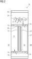
- the Fig. 2 the electrolysis cell 01 Fig. 1 in a cross-section through the hydrogen chamber 25 and the anode water chamber 16.
- the structure of the electrolysis cell 01 can be seen with a one-piece housing 02.
- This 02 is divided into several chambers, whereby the presence of an anode chamber 11 on the anode side 10 and the cathode chamber 21 on the cathode side 20 is essential for the function of water electrolysis.
- the anode chamber 11 is separated from the cathode chamber 21 by a membrane 05.
- This can be a so-called PEM (polymer electrolyte membrane), which is sufficiently known to the person skilled in the art.
- PEM polymer electrolyte membrane
- Also required for the function is the arrangement of an anode 12 in the anode chamber 11 and a cathode 22 in the cathode chamber 21.
- an electrical connection is also required, which will not be discussed further here and in this respect reference is made to embodiments that are sufficiently known to the person skilled in the art.
- a water supply from the underside is also required.
- a water inlet 14 is provided in the housing 02 on the underside of the anode chamber 11, which provides a connection to an anode water chamber 16 located below.
- a water inlet 24 is also provided on the underside of the cathode chamber 21 in the housing 02. This water inlet 24 forms the connection to the cathode water chamber 26 located below.
- the anode water chamber 16 is separated from the adjacent cathode water chamber 26 by a water partition 07 of the housing 02.
- the anode water chamber 16 and the cathode water chamber 26 as well as the water partition wall 07 extend from the anode side 10 to the cathode side 20. Consequently, the anode water chamber 16 and the cathode water chamber 26 are open on both sides.
- an oxygen outlet 13 is provided at the top of the anode chamber 11 in the housing 02.
- the housing 02 has a hydrogen outlet 23 above the cathode chamber 21.
- the inventive design of the electrolysis cell 01 is the presence of an oxygen chamber 15 in the housing 02 above the oxygen outlet 13 and the presence of a hydrogen chamber 25 in the housing 02 above the hydrogen outlet 23.
- the oxygen chamber 15 is partially filled with the oxygen formed and with water.
- the hydrogen chamber 25 contains hydrogen and water.
- the volume of the oxygen chamber and the volume of the hydrogen chamber must be selected to be sufficiently large.
- the volume of the oxygen chamber corresponds approximately to 0.25 times the volume of the anode chamber 11.
- the volume of the hydrogen chamber which has approximately 0.25 times the volume of the cathode chamber 21.
- FIG. 1 and Fig. 2 Also shown is the advantageous arrangement of the oxygen chamber 15 adjacent to the hydrogen chamber 25. These 15 and 25 are separated from each other by a gas partition 06. Accordingly, the oxygen chamber 15 and the hydrogen chamber 25, as well as the gas partition 06, extend from the anode side 10 to the cathode side 20. The oxygen chamber 15 and the hydrogen chamber 25 are open on both sides.
- cathode cover 27 on the cathode side 20 of the cathode chamber 21.
- the cathode cover 27 is intended to be welded to the housing 02 or otherwise sealed tightly. This results in a separation of the adjacent anode chamber 11 and cathode chamber 21 when electrolysis cells 01 are stacked.
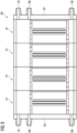
- FIG. 3 An exemplary embodiment of an electrolysis unit 09 is now schematically illustrated.
- the stacked arrangement of several electrolysis cells 01 can be seen. These cells 01 are sealed against each other. This can be achieved, for example, by welding or seals.
- a first cover plate 03 is arranged on the anode side 10 of a first electrolysis cell 01, and a second cover plate 04 is arranged opposite on the cathode side 20 of a last electrolysis cell 01. This seals the individual chambers, i.e., the oxygen chamber 15, the anode water chamber 16, the hydrogen chamber 25, and the cathode water chamber 26.
- the end covers 03, 04 each have several water connections 08. Furthermore, an oxygen connection 18 and a hydrogen connection 28 are located offset from one another at the upper end of the end covers 03, 04. Although not shown correctly, it is obvious that the oxygen connection 18 leads to the oxygen chamber 15 and the hydrogen connection 28 to the hydrogen chamber 25.
- the design of the connections is obviously based on the respective medium being carried and the volume flow.
Landscapes
- Chemical & Material Sciences (AREA)
- Engineering & Computer Science (AREA)
- Chemical Kinetics & Catalysis (AREA)
- Electrochemistry (AREA)
- Materials Engineering (AREA)
- Metallurgy (AREA)
- Organic Chemistry (AREA)
- Inorganic Chemistry (AREA)
- Electrolytic Production Of Non-Metals, Compounds, Apparatuses Therefor (AREA)
Claims (11)
- Cellule (01) d'électrolyse comme partie constitutive conforme aux prescriptions d'une unité (09) d'électrolyse pour la décomposition électrochimique de l'eau (H2O) en hydrogène et en oxygène ayant un côté (10) anodique et un côté (20) cathodique comprenant une enveloppe (02), dans laquelle est disposée une chambre (11) anodique ayant une anode (12) et, en face, une chambre (21) cathodique ayant une cathode (22) et, entre elles, une membrane (05), dans laquelle, conformément aux prescriptions, une tension peut être appliquée entre l'anode (12) et la cathode (22), dans laquelle, du côté supérieur de la chambre (11) anodique est disposée une sortie (13) pour l'oxygène et, du côté supérieur de la chambre (21) cathodique, une sortie (23) pour l'hydrogène et, du côté inférieur de la chambre (11) anodique et/ou du côté inférieur de la chambre (21) cathodique, une entrée (14, 24) pour l'eau, dans laquelle, dans l'enveloppe (02), est disposée en outre, au-dessus de la sortie (13) pour l'oxygène, une chambre (15) pour l'oxygène ayant un volume représentant au moins 0,15 fois le volume de la chambre (11) anodique et, au-dessus de la sortie (23) pour l'hydrogène, une chambre (25) pour l'hydrogène ayant un volume représentant au moins 0,15 fois le volume de la chambre (21) cathodique,
caractérisée
en ce que, dans l'enveloppe (02) du côté inférieur de l'entrée (14) pour l'eau du côté anodique, est disposée une chambre (16) pour de l'eau du côté anodique ayant un volume représentant au moins 0,05 fois le volume de la chambre (11) anodique et, du côté inférieur de l'entrée (24) pour de l'eau du côté cathodique, est disposée une chambre (26) pour de l'eau cathodique ayant un volume représentant au moins 0,05 fois le volume de la chambre (11) cathodique. - Cellule (01) d'électrolyse suivant la revendication 1, dans laquelle l'enveloppe (02) est réalisée en une seule pièce.
- Cellule (01) d'électrolyse suivant la revendication 1 ou 2, dans laquelle l'enveloppe (02) est en une matière plastique.
- Cellule (01) d'électrolyse suivant l'une des revendications 1 à 3,
dans laquelle la chambre (15) pour l'oxygène et la chambre (25) pour l'hydrogène sont ouvertes du côté (10) anodique et du côté (20) cathodique. - Cellule (01) d'électrolyse suivant l'une des revendications 1 à 4,
dans laquelle la chambre (16) pour de l'eau anodique et/ou la chambre (26) pour de l'eau cathodique sont ouvertes du côté (10) anodique et du côté (20) cathodique. - Cellule (01) d'électrolyse suivant l'une des revendications 1 à 5,dans laquelle la chambre (11) anodique est ouverte du côté (10) anodique et/ou la chambre (21) cathodique est ouverte du côté (20) cathodique ; et/oudans laquelle la chambre (11) anodique est fermée du côté (10) anodique par un couvercle anodique fixé à l'enveloppe et/ou dans laquelle la chambre (21) cathodique est fermée du côté (20) cathodique par un couvercle (27) cathodique fixé à l'enveloppe.
- Unité (09) d'électrolyse pour la décomposition électrochimique de l'eau (H20) en hydrogène et en oxygène comprenant une pluralité de cellules (01) d'électrolyse disposées en étant voisines les unes des autres respectivement suivant l'une des revendications précédentes.
- Unité (09) d'électrolyse suivant la revendication 7,
dans laquelle, du côté (10) anodique d'une première cellule (01) d'électrolyse est disposé un premier couvercle (03) de fermeture et, du côté (20) cathodique d'une dernière cellule (01) d'électrolyse, est disposé un deuxième couvercle (04) de fermeture, dans laquelle le premier couvercle (03) de fermeture et le deuxième couvercle (04) de fermeture ferment la chambre (15) pour l'oxygène et la chambre (25) pour l'hydrogène et les chambres (16, 26) pour l'eau, qui sont présentes. - Unité (09) d'électrolyse suivant la revendication 8,
dans laquelle le premier couvercle (03) de fermeture et/ou le deuxième couvercle (04) de fermeture dispose :- d'un raccord (18) pour l'oxygène à la chambre (15) pour l'oxygène et/ou- d'un raccord (28) pour l'hydrogène à la chambre (25) pour de l'hydrogène et/ou- d'un raccord (08) pour l'eau à une chambre (15, 16, 25, 26) ou plusieurs raccords (08) pour l'eau à plusieurs chambres (15, 16, 25, 26). - Unité (09) d'électrolyse suivant la revendication 8 ou 9, dans laquelle le premier couvercle (03) de fermeture et le deuxième couvercle (04) de fermeture sont réalisés sous la forme de pièces pareilles.
- Unité (09) d'électrolyse suivant l'une des revendications 7 à 10,
dans laquelle les cellules (01) d'électrolyse sont montées électriquement en série.
Priority Applications (2)
| Application Number | Priority Date | Filing Date | Title |
|---|---|---|---|
| EP21179398.9A EP4105358B1 (fr) | 2021-06-15 | 2021-06-15 | Cellule d'électrolyse et unité d'électrolyse pour la décomposition électrochimique de l'eau |
| ES21179398T ES3034248T3 (en) | 2021-06-15 | 2021-06-15 | Electrolytic cell and electrolysis unit for electrochemical decomposition of water |
Applications Claiming Priority (1)
| Application Number | Priority Date | Filing Date | Title |
|---|---|---|---|
| EP21179398.9A EP4105358B1 (fr) | 2021-06-15 | 2021-06-15 | Cellule d'électrolyse et unité d'électrolyse pour la décomposition électrochimique de l'eau |
Publications (3)
| Publication Number | Publication Date |
|---|---|
| EP4105358A1 EP4105358A1 (fr) | 2022-12-21 |
| EP4105358B1 true EP4105358B1 (fr) | 2025-04-30 |
| EP4105358C0 EP4105358C0 (fr) | 2025-04-30 |
Family
ID=76483041
Family Applications (1)
| Application Number | Title | Priority Date | Filing Date |
|---|---|---|---|
| EP21179398.9A Active EP4105358B1 (fr) | 2021-06-15 | 2021-06-15 | Cellule d'électrolyse et unité d'électrolyse pour la décomposition électrochimique de l'eau |
Country Status (2)
| Country | Link |
|---|---|
| EP (1) | EP4105358B1 (fr) |
| ES (1) | ES3034248T3 (fr) |
Families Citing this family (3)
| Publication number | Priority date | Publication date | Assignee | Title |
|---|---|---|---|---|
| CN116815214A (zh) * | 2023-06-28 | 2023-09-29 | 远景氢能源科技(江苏)有限公司 | 一种电解槽装置与方法 |
| EP4570955A1 (fr) * | 2023-12-12 | 2025-06-18 | TotalEnergies OneTech | Cellule d'électrolyseur d'eau, empilement associé de cellules d'électrolyseur d'eau et procédé |
| DE102024201327A1 (de) * | 2024-02-14 | 2025-08-14 | Siemens Energy Global GmbH & Co. KG | Verfahren zum Betrieb eines Elektrolyseurs und Elektrolyseur |
Family Cites Families (4)
| Publication number | Priority date | Publication date | Assignee | Title |
|---|---|---|---|---|
| EP1528126A1 (fr) * | 2003-10-30 | 2005-05-04 | Vandenborre Hydrogen Systems N.V. | Module d'électrolyseur intégré avec separateur gaz/liquide |
| WO2006060912A1 (fr) * | 2004-12-07 | 2006-06-15 | Stuart Energy Systems Corporation | Electrolyseur et composants les contenant. |
| US20130140171A1 (en) * | 2008-07-15 | 2013-06-06 | Next Hydrogen Corporation | Electrolyser module |
| EP3599292A1 (fr) | 2018-07-27 | 2020-01-29 | Siemens Aktiengesellschaft | Unité d'électrolyse et procédé de fonctionnement de l'unité d'électrolyse |
-
2021
- 2021-06-15 EP EP21179398.9A patent/EP4105358B1/fr active Active
- 2021-06-15 ES ES21179398T patent/ES3034248T3/es active Active
Also Published As
| Publication number | Publication date |
|---|---|
| ES3034248T3 (en) | 2025-08-14 |
| EP4105358A1 (fr) | 2022-12-21 |
| EP4105358C0 (fr) | 2025-04-30 |
Similar Documents
| Publication | Publication Date | Title |
|---|---|---|
| EP0947024B1 (fr) | Batterie de piles a combustible a refroidissement liquide | |
| EP3797182B1 (fr) | Unité d'électrolyse et procédé de fonctionnement de l'unité d'électrolyse | |
| EP4105358B1 (fr) | Cellule d'électrolyse et unité d'électrolyse pour la décomposition électrochimique de l'eau | |
| DE102011007378B4 (de) | Brennstoffzellenstapel mit einer Wasserablaufanordnung | |
| DE102013216587B4 (de) | Geometrie eines hocheffizienten Medienverteilers für eine Elektrolysezelle und einen Elektrolysestack | |
| DD211130A5 (de) | Elektrodenbauteil | |
| EP3489394A1 (fr) | Électrolyseur pour électrolyse pem à basse pression | |
| WO2023062081A2 (fr) | Cadre pour cellules électrolytiques à pem et empilement de cellules électrolytiques à pem pour la production d'hydrogène haute pression par électrolyse à pression différentielle | |
| DE102020215014A1 (de) | Bipolarplatte für eine elektrochemische Zelle und elektrochemische Zelle | |
| DE102005056341B4 (de) | Brennstoffzelle | |
| WO2019228616A1 (fr) | Empilement de cellules pem | |
| WO2020109436A1 (fr) | Structure de distribution pour pile à combustible ou électrolyseur | |
| EP3526372B1 (fr) | Cellule électrolytique ayant une électrode à diffusion gazeuse et son procédé de fonctionnement | |
| EP3476000B1 (fr) | Dispositif de conversion d'énergie, en particulier pile à combustible ou électrolyseur | |
| DE10355485A1 (de) | Brennstoffzelle | |
| DE102020114066A1 (de) | Bipolarplatte | |
| EP2141264B1 (fr) | Dispositif destiné à produire un mélange d'oxygène/hydrogène | |
| DE102008054370A1 (de) | Wartungsfreie und kontinuierliche Kühlmittelaufbereitung in Brennstoffzellenfahrzeugen mittels Elektro-Deionisation (EDI) mit vorteilhafter Ionenentnahme | |
| DE102023124818A1 (de) | Wasserelektrolysevorrichtung und wasserelektrolysesystem mit wasserelektrolysevorrichtung | |
| EP2671974B1 (fr) | Système d'alimentation en eau pure pour les appareils de dialyse | |
| EP4364221A1 (fr) | Plaque bipolaire pour la délimitation chimique et le montage en série électrique de piles à combustible pem ou d'électrolyseurs pem empilé(e)s | |
| DE102012006642A1 (de) | Durchflussbatterie, elektrochemischer Energiewandler für eine Durchflussbatterie, Zellrahmen und Bipolarplatte sowie Kollektorplatte | |
| WO2022122080A1 (fr) | Tôle formant électrode destinée à une batterie redox et batterie redox | |
| DE102010001760A1 (de) | Energiespeicher- und Stromerzeugungssystem | |
| DE102016225573A1 (de) | Bipolarplatte für eine Brennstoffzelle und Brennstoffzelle |
Legal Events
| Date | Code | Title | Description |
|---|---|---|---|
| PUAI | Public reference made under article 153(3) epc to a published international application that has entered the european phase |
Free format text: ORIGINAL CODE: 0009012 |
|
| STAA | Information on the status of an ep patent application or granted ep patent |
Free format text: STATUS: THE APPLICATION HAS BEEN PUBLISHED |
|
| AK | Designated contracting states |
Kind code of ref document: A1 Designated state(s): AL AT BE BG CH CY CZ DE DK EE ES FI FR GB GR HR HU IE IS IT LI LT LU LV MC MK MT NL NO PL PT RO RS SE SI SK SM TR |
|
| STAA | Information on the status of an ep patent application or granted ep patent |
Free format text: STATUS: REQUEST FOR EXAMINATION WAS MADE |
|
| 17P | Request for examination filed |
Effective date: 20230103 |
|
| RBV | Designated contracting states (corrected) |
Designated state(s): AL AT BE BG CH CY CZ DE DK EE ES FI FR GB GR HR HU IE IS IT LI LT LU LV MC MK MT NL NO PL PT RO RS SE SI SK SM TR |
|
| STAA | Information on the status of an ep patent application or granted ep patent |
Free format text: STATUS: EXAMINATION IS IN PROGRESS |
|
| 17Q | First examination report despatched |
Effective date: 20240919 |
|
| GRAP | Despatch of communication of intention to grant a patent |
Free format text: ORIGINAL CODE: EPIDOSNIGR1 |
|
| STAA | Information on the status of an ep patent application or granted ep patent |
Free format text: STATUS: GRANT OF PATENT IS INTENDED |
|
| INTG | Intention to grant announced |
Effective date: 20241213 |
|
| GRAS | Grant fee paid |
Free format text: ORIGINAL CODE: EPIDOSNIGR3 |
|
| GRAA | (expected) grant |
Free format text: ORIGINAL CODE: 0009210 |
|
| STAA | Information on the status of an ep patent application or granted ep patent |
Free format text: STATUS: THE PATENT HAS BEEN GRANTED |
|
| AK | Designated contracting states |
Kind code of ref document: B1 Designated state(s): AL AT BE BG CH CY CZ DE DK EE ES FI FR GB GR HR HU IE IS IT LI LT LU LV MC MK MT NL NO PL PT RO RS SE SI SK SM TR |
|
| REG | Reference to a national code |
Ref country code: CH Ref legal event code: EP Ref country code: GB Ref legal event code: FG4D Free format text: NOT ENGLISH |
|
| REG | Reference to a national code |
Ref country code: IE Ref legal event code: FG4D Free format text: LANGUAGE OF EP DOCUMENT: GERMAN |
|
| U01 | Request for unitary effect filed |
Effective date: 20250505 |
|
| U07 | Unitary effect registered |
Designated state(s): AT BE BG DE DK EE FI FR IT LT LU LV MT NL PT RO SE SI Effective date: 20250509 |
|
| PGFP | Annual fee paid to national office [announced via postgrant information from national office to epo] |
Ref country code: GB Payment date: 20250617 Year of fee payment: 5 |
|
| PGFP | Annual fee paid to national office [announced via postgrant information from national office to epo] |
Ref country code: NO Payment date: 20250617 Year of fee payment: 5 |
|
| U20 | Renewal fee for the european patent with unitary effect paid |
Year of fee payment: 5 Effective date: 20250624 |
|
| REG | Reference to a national code |
Ref country code: ES Ref legal event code: FG2A Ref document number: 3034248 Country of ref document: ES Kind code of ref document: T3 Effective date: 20250814 |
|
| PGFP | Annual fee paid to national office [announced via postgrant information from national office to epo] |
Ref country code: ES Payment date: 20250710 Year of fee payment: 5 |
|
| PG25 | Lapsed in a contracting state [announced via postgrant information from national office to epo] |
Ref country code: GR Free format text: LAPSE BECAUSE OF FAILURE TO SUBMIT A TRANSLATION OF THE DESCRIPTION OR TO PAY THE FEE WITHIN THE PRESCRIBED TIME-LIMIT Effective date: 20250731 |
|
| PG25 | Lapsed in a contracting state [announced via postgrant information from national office to epo] |
Ref country code: PL Free format text: LAPSE BECAUSE OF FAILURE TO SUBMIT A TRANSLATION OF THE DESCRIPTION OR TO PAY THE FEE WITHIN THE PRESCRIBED TIME-LIMIT Effective date: 20250430 |
|
| PG25 | Lapsed in a contracting state [announced via postgrant information from national office to epo] |
Ref country code: HR Free format text: LAPSE BECAUSE OF FAILURE TO SUBMIT A TRANSLATION OF THE DESCRIPTION OR TO PAY THE FEE WITHIN THE PRESCRIBED TIME-LIMIT Effective date: 20250430 |
|
| PGFP | Annual fee paid to national office [announced via postgrant information from national office to epo] |
Ref country code: CH Payment date: 20250701 Year of fee payment: 5 |
|
| PG25 | Lapsed in a contracting state [announced via postgrant information from national office to epo] |
Ref country code: RS Free format text: LAPSE BECAUSE OF FAILURE TO SUBMIT A TRANSLATION OF THE DESCRIPTION OR TO PAY THE FEE WITHIN THE PRESCRIBED TIME-LIMIT Effective date: 20250731 |
|
| PG25 | Lapsed in a contracting state [announced via postgrant information from national office to epo] |
Ref country code: IS Free format text: LAPSE BECAUSE OF FAILURE TO SUBMIT A TRANSLATION OF THE DESCRIPTION OR TO PAY THE FEE WITHIN THE PRESCRIBED TIME-LIMIT Effective date: 20250830 |
|
| PG25 | Lapsed in a contracting state [announced via postgrant information from national office to epo] |
Ref country code: SM Free format text: LAPSE BECAUSE OF FAILURE TO SUBMIT A TRANSLATION OF THE DESCRIPTION OR TO PAY THE FEE WITHIN THE PRESCRIBED TIME-LIMIT Effective date: 20250430 |
|
| PG25 | Lapsed in a contracting state [announced via postgrant information from national office to epo] |
Ref country code: CZ Free format text: LAPSE BECAUSE OF FAILURE TO SUBMIT A TRANSLATION OF THE DESCRIPTION OR TO PAY THE FEE WITHIN THE PRESCRIBED TIME-LIMIT Effective date: 20250430 |
|
| PG25 | Lapsed in a contracting state [announced via postgrant information from national office to epo] |
Ref country code: SK Free format text: LAPSE BECAUSE OF FAILURE TO SUBMIT A TRANSLATION OF THE DESCRIPTION OR TO PAY THE FEE WITHIN THE PRESCRIBED TIME-LIMIT Effective date: 20250430 |
|
| PG25 | Lapsed in a contracting state [announced via postgrant information from national office to epo] |
Ref country code: MC Free format text: LAPSE BECAUSE OF FAILURE TO SUBMIT A TRANSLATION OF THE DESCRIPTION OR TO PAY THE FEE WITHIN THE PRESCRIBED TIME-LIMIT Effective date: 20250430 |
|
| PLBE | No opposition filed within time limit |
Free format text: ORIGINAL CODE: 0009261 |
|
| STAA | Information on the status of an ep patent application or granted ep patent |
Free format text: STATUS: NO OPPOSITION FILED WITHIN TIME LIMIT |
|
| REG | Reference to a national code |
Ref country code: CH Ref legal event code: L10 Free format text: ST27 STATUS EVENT CODE: U-0-0-L10-L00 (AS PROVIDED BY THE NATIONAL OFFICE) Effective date: 20260311 |
|
| 26N | No opposition filed |
Effective date: 20260202 |
|
| PG25 | Lapsed in a contracting state [announced via postgrant information from national office to epo] |
Ref country code: IE Free format text: LAPSE BECAUSE OF NON-PAYMENT OF DUE FEES Effective date: 20250615 |