EP4105498B1 - Kit und verfahren zur montage eines elements eines möbelstücks und element eines möbelstücks - Google Patents
Kit und verfahren zur montage eines elements eines möbelstücks und element eines möbelstücks Download PDFInfo
- Publication number
- EP4105498B1 EP4105498B1 EP22020262.6A EP22020262A EP4105498B1 EP 4105498 B1 EP4105498 B1 EP 4105498B1 EP 22020262 A EP22020262 A EP 22020262A EP 4105498 B1 EP4105498 B1 EP 4105498B1
- Authority
- EP
- European Patent Office
- Prior art keywords
- longitudinal
- kit according
- elongate
- cross
- hole
- Prior art date
- Legal status (The legal status is an assumption and is not a legal conclusion. Google has not performed a legal analysis and makes no representation as to the accuracy of the status listed.)
- Active
Links
Images


Classifications
-
- F—MECHANICAL ENGINEERING; LIGHTING; HEATING; WEAPONS; BLASTING
- F16—ENGINEERING ELEMENTS AND UNITS; GENERAL MEASURES FOR PRODUCING AND MAINTAINING EFFECTIVE FUNCTIONING OF MACHINES OR INSTALLATIONS; THERMAL INSULATION IN GENERAL
- F16B—DEVICES FOR FASTENING OR SECURING CONSTRUCTIONAL ELEMENTS OR MACHINE PARTS TOGETHER, e.g. NAILS, BOLTS, CIRCLIPS, CLAMPS, CLIPS OR WEDGES; JOINTS OR JOINTING
- F16B12/00—Jointing of furniture or the like, e.g. hidden from exterior
- F16B12/44—Leg joints; Corner joints
- F16B12/46—Non-metal corner connections
-
- A—HUMAN NECESSITIES
- A47—FURNITURE; DOMESTIC ARTICLES OR APPLIANCES; COFFEE MILLS; SPICE MILLS; SUCTION CLEANERS IN GENERAL
- A47C—CHAIRS; SOFAS; BEDS
- A47C4/00—Foldable, collapsible or dismountable chairs
- A47C4/02—Dismountable chairs
- A47C4/021—Dismountable chairs connected by slotted joints
-
- A—HUMAN NECESSITIES
- A47—FURNITURE; DOMESTIC ARTICLES OR APPLIANCES; COFFEE MILLS; SPICE MILLS; SUCTION CLEANERS IN GENERAL
- A47C—CHAIRS; SOFAS; BEDS
- A47C9/00—Stools for specified purposes
-
- F—MECHANICAL ENGINEERING; LIGHTING; HEATING; WEAPONS; BLASTING
- F16—ENGINEERING ELEMENTS AND UNITS; GENERAL MEASURES FOR PRODUCING AND MAINTAINING EFFECTIVE FUNCTIONING OF MACHINES OR INSTALLATIONS; THERMAL INSULATION IN GENERAL
- F16B—DEVICES FOR FASTENING OR SECURING CONSTRUCTIONAL ELEMENTS OR MACHINE PARTS TOGETHER, e.g. NAILS, BOLTS, CIRCLIPS, CLAMPS, CLIPS OR WEDGES; JOINTS OR JOINTING
- F16B12/00—Jointing of furniture or the like, e.g. hidden from exterior
- F16B12/10—Jointing of furniture or the like, e.g. hidden from exterior using pegs, bolts, tenons, clamps, clips, or the like
- F16B12/12—Jointing of furniture or the like, e.g. hidden from exterior using pegs, bolts, tenons, clamps, clips, or the like for non-metal furniture parts, e.g. made of wood, of plastics
- F16B12/125—Jointing of furniture or the like, e.g. hidden from exterior using pegs, bolts, tenons, clamps, clips, or the like for non-metal furniture parts, e.g. made of wood, of plastics using mortise and tenon joints
-
- F—MECHANICAL ENGINEERING; LIGHTING; HEATING; WEAPONS; BLASTING
- F16—ENGINEERING ELEMENTS AND UNITS; GENERAL MEASURES FOR PRODUCING AND MAINTAINING EFFECTIVE FUNCTIONING OF MACHINES OR INSTALLATIONS; THERMAL INSULATION IN GENERAL
- F16B—DEVICES FOR FASTENING OR SECURING CONSTRUCTIONAL ELEMENTS OR MACHINE PARTS TOGETHER, e.g. NAILS, BOLTS, CIRCLIPS, CLAMPS, CLIPS OR WEDGES; JOINTS OR JOINTING
- F16B12/00—Jointing of furniture or the like, e.g. hidden from exterior
- F16B12/10—Jointing of furniture or the like, e.g. hidden from exterior using pegs, bolts, tenons, clamps, clips, or the like
- F16B12/12—Jointing of furniture or the like, e.g. hidden from exterior using pegs, bolts, tenons, clamps, clips, or the like for non-metal furniture parts, e.g. made of wood, of plastics
- F16B12/20—Jointing of furniture or the like, e.g. hidden from exterior using pegs, bolts, tenons, clamps, clips, or the like for non-metal furniture parts, e.g. made of wood, of plastics using clamps, clips, wedges, sliding bolts, or the like
- F16B12/2009—Jointing of furniture or the like, e.g. hidden from exterior using pegs, bolts, tenons, clamps, clips, or the like for non-metal furniture parts, e.g. made of wood, of plastics using clamps, clips, wedges, sliding bolts, or the like actuated by rotary motion
-
- A—HUMAN NECESSITIES
- A47—FURNITURE; DOMESTIC ARTICLES OR APPLIANCES; COFFEE MILLS; SPICE MILLS; SUCTION CLEANERS IN GENERAL
- A47B—TABLES; DESKS; OFFICE FURNITURE; CABINETS; DRAWERS; GENERAL DETAILS OF FURNITURE
- A47B13/00—Details of tables or desks
- A47B13/02—Underframes
- A47B13/04—Underframes of wood
-
- A—HUMAN NECESSITIES
- A47—FURNITURE; DOMESTIC ARTICLES OR APPLIANCES; COFFEE MILLS; SPICE MILLS; SUCTION CLEANERS IN GENERAL
- A47B—TABLES; DESKS; OFFICE FURNITURE; CABINETS; DRAWERS; GENERAL DETAILS OF FURNITURE
- A47B47/00—Cabinets, racks or shelf units, characterised by features related to dismountability or building-up from elements
- A47B47/04—Cabinets, racks or shelf units, characterised by features related to dismountability or building-up from elements made mainly of wood or plastics
- A47B47/05—Cabinets, racks or shelf units, characterised by features related to dismountability or building-up from elements made mainly of wood or plastics with panels on a separate frame, e.g. a metal frame
-
- A—HUMAN NECESSITIES
- A47—FURNITURE; DOMESTIC ARTICLES OR APPLIANCES; COFFEE MILLS; SPICE MILLS; SUCTION CLEANERS IN GENERAL
- A47C—CHAIRS; SOFAS; BEDS
- A47C4/00—Foldable, collapsible or dismountable chairs
- A47C4/02—Dismountable chairs
Definitions
- the invention relates to a kit for assembling a piece of furniture, such as a stool or a chair.
- the invention also relates to a method for assembling a furniture element as well as to a furniture element mounted using at least one kit according to the invention.
- sectional and modular furniture are very popular because they allow great freedom of dimensions and shapes, which makes them easily integrated into a home.
- the aim of the invention is to offer a user more possibilities of creation, so that he can obtain more shapes, and this in a simple and rapid manner and by using, on the one hand, a number limited number of assembly elements and, on the other hand, few tools for assembling a piece of furniture.
- the invention relates to a method of assembling a furniture element according to claim 12.
- the subject of the invention is a furniture element assembled using at least one example of the aforementioned kit, in particular, by implementing the assembly method which has just been presented.
- Such an element of furniture offers in particular the advantage of being able to be assembled and disassembled an unlimited number of times, of being able to be easily supplemented or lightened by removing certain of its constituent parts.
- the invention makes it possible to assemble sectional, modular, scalable furniture, composed of sufficiently rigid solid materials such as solid wood, plywood, certain plastic materials, metals, etc.
- the kit according to the invention must first include elongated parts. These are generally pieces with a polygonal base developing regularly along a longitudinal axis.
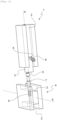
- Such an elongated part 1 is shown on the figures 1 to 3 .
- the values a and b are preferably equal in order to simplify the manufacturing of elongated parts.
- the tenon 3 is able to be inserted into a longitudinal groove 2 of a second elongated part 4 identical or similar to the elongated part 1.
- the elongated part 1 comprises a first longitudinal hole 5 in the tenon 3, preferably in the middle, as well as a second transverse hole 6, preferably made in the transverse groove 2, and which opens into the first longitudinal hole 5.
- the second elongated part 4 comprises a third hole 9, transverse, in its longitudinal groove 2, that is to say perpendicular to the axis its longitudinal axis X.
- a first fixing element 7 can penetrate partially into the first hole 5 of the first elongated part 1 and partially into the third hole 9 of the second elongated part 4.
- a second fixing element 8 can partially penetrate into the second hole 6.
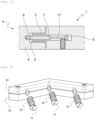
- first 7 and second 8 fixing elements On the figure 5 are shown in detail examples of first 7 and second 8 fixing elements and, on the Figure 6 , their cooperation with a view to maintaining the first and second elongated parts 1.4 together.
- the first fixing element 7 can be a pin, one end of which is threaded and screwed into the third tapped transverse hole 9 provided at the bottom of the groove 2 of the second elongated element 4.
- the other end of the first fixing element 7 is at the inside the first longitudinal hole 5 of the first elongated part 1.
- the second fixing element 8 may be a screw with a conical tip screwed into the second tapped transverse hole 6 of the first elongated part 1 until its conical tip exerts a force on the first fixing element 7 aimed at bringing the two closer together. elongated parts 1 and 4 and to immobilize them, thanks to a longitudinal section 17 of reduced diameter of the fixing element 7.
- means are provided to reinforce the assembly of the first and second elongated parts 1.4.
- These means of reinforcement consist of two brackets 10 visible on the Figure 6 , which are preferably identical and whose sum of thicknesses is slightly less than the width of the grooves 2, which allows the brackets to be inserted into these grooves and in an angle formed by them, as can be seen on there Figure 7 .
- circular and tapped holes are provided with one axial cylindrical half in one bracket and the other axial cylindrical half in the other bracket. These holes are preferably inclined by 45 or 135 degrees relative to the longitudinal axis of the arms of the brackets in which they are located.
- their entrances are chamfered to receive the slotted conical heads 11 of slotted conical head screws 12.
- the faces of the brackets 10 intended to be turned towards the walls of the longitudinal grooves 2 are provided with mini-pins to increase the friction between the brackets and these walls.
- the screws 12 can be self-drilling. With other materials, it is necessary that the bracket holes be threaded.
- the elongated parts 1 and 4 are intended to be used for the assembly of other parts such as spars or slats 15 visible on the figure 8 .
- the elongated parts 1 and 4 are then preferably provided with additional longitudinal grooves 13,14, visible in particular on the figure 1 , to accommodate the end of these slats 15.
- the thickness of the slats 15 is therefore substantially equal to the width of the longitudinal grooves 13,14 intended to accommodate them.
- the longitudinal grooves 2 and the additional longitudinal grooves 13,14 have the same dimensions so that they can be used equally with a tenon or a slat.
- the kit according to the invention can also be provided with parallelepiped filling elements or bars 16 whose cross section has the same surface as the cross section of a longitudinal groove 2 or an additional longitudinal groove 13,14.
- These parallelepiped filling elements 16 have at least two functions: an aesthetic function, because they can provide a different shade or shade, and a technical function since by filling a groove, they prevent the edges of the groove from injuring a user, snag clothing, harbor dirt, etc.
- the tenons always have a width a, a length greater than a, preferably greater than 2 a and more preferably equal to (a + 2 b) as well as preferably a thickness of value a.
- the cross section of the elongated part of the Figure 9 corresponds to a rectangle of length (3 a + 2 b ) and width (2 a + 2 b) from which we have removed 5 squares of side a, two at the level of two angles of the same length (in the sense of longitudinal side ), one in the middle of this same length, then two in the middle of the two remaining widths (in the sense of transverse side).
- the cross section of the elongated part of the Figure 10 is identical to that of the elongated part of the Figure 9 , but the tenon 3 is perpendicular to that of the Figure 9 .
- the cross section of the elongated part of the Figure 11 corresponds to a square of side (2 a + 2 b) from which we have removed 3 squares of side a, two in the middle of two adjacent sides, then one at the angle formed by these two sides.
- the cross section of the elongated part of the Figure 12 corresponds to a rectangle of length (3 a + 2 b) and width ( a + 2 b) from which 2 squares of side a have been removed, in the middle of the two widths (transverse sides).
- the elongated pieces have lengths which depend on the dimensions of the furniture that we intend to manufacture.
- the second fixing element 8 can be a grub screw. It can also be, for certain materials such as wood, self-tapping when screwing into hole 6. For other materials, it is necessary that hole 6 be tapped. Alternatively, it is possible to insert an insert with a central tapped recess into hole 6.
- slats in particular three, of different widths but of the same length, the narrowest slats being intended to be arranged at the ends of the panels that we wish to manufacture.
- the narrowest slats being intended to be arranged at the ends of the panels that we wish to manufacture.
- the manufacturing of the narrowest slats can be done simply by cutting the widest slats longitudinally.
- An innumerable number of pieces of furniture of different shapes and dimensions can be created by assembling elongated pieces according to the invention having cross sections such as those represented on the figure 2 , 10 , 11 and 12 and slats of varying widths.
- FIG 13 is represented an assembly composed of a vertical part 1 following the figure 1 and two horizontal pieces 1 following the Figure 3 .
- the assembly of the Figure 14 is composed of a vertical part 1 conforming to the figure 1 and a vertical piece 1 conforming to the Figure 3 .
- Rods 16 were inserted vertically and horizontally in certain grooves of these parts.
- the stool of the figure 8 was made with elongated pieces whose length of side a was 11 mm and that of side b was 8 mm.
- Four elongated pieces of the figure 2 , four of the Figure 11 and four of the Figure 12 were used, as well as slats 15 and bars 16.
- the bars 16 received in the longitudinal grooves 2,13,14 can be fixed by gluing, by tight fitting or by any other appropriate means.
- the invention therefore makes it possible to personalize furniture and is particularly suitable for the manufacture of solid wood furniture from profiles which can be easily manufactured in series, then cut to the right length before machining the longitudinal grooves as well. that, where applicable, the longitudinal clearances 17 in the shape of an L or angle iron (cf. Fig. 2 ) in the corners.
- the formed objects can be assembled and disassembled an unlimited number of times, supplemented and certain parts can be removed easily.
Landscapes
- Engineering & Computer Science (AREA)
- General Engineering & Computer Science (AREA)
- Mechanical Engineering (AREA)
- Furniture Connections (AREA)
- Special Chairs (AREA)
Claims (15)
- Kit zur Montage eines Elements eines Möbelstücks mit :- mindestens einem ersten längliches Teil (1) und einem zweiten länglichen Teil (4), die jeweils eine Längsachse (X) und mindestens eine Längsnut (2) parallel zu dieser Längsachse (X) aufweisen; wobei die beiden Längsnuten (2) denselben Querschnitt haben, wobei das erste längliche Teil (1) an einem Längsende einen Zapfen (3) aufweist, der geeignet ist, in die Längsnut (2) des zweiten länglichen Teils (4) eingeführt zu werden; wobei ein erstes, längs verlaufendes Loch (5) in dem Zapfen (3) und ein zweites, quer verlaufendes Loch (6) in dem ersten länglichen Teil (1) vorgesehen ist und in das erste längs verlaufende Loch (5) mündet; wobei ein drittes, quer verlaufendes Loch (9) in der Längsnut (2) des zweiten länglichen Teils (4) vorgesehen ist;- einem ersten Befestigungselement (7), das dazu geeignet ist, teilweise in das erste Loch (5) und teilweise in das dritte Loch (9) einzudringen; und- einem zweiten Befestigungselement (8), das dazu geeignet ist, zumindest teilweise in das zweite Loch (6) einzudringen; wobei das erste und das zweite Befestigungselement (7, 8) geeignet sind, miteinander zusammenzuwirken, um das erste und das zweite längliche Teil (1, 4) zusammenzuhalten;dadurch gekennzeichnet, dass es außerdem Mittel (10, 11) zur Verstärkung der Verbindung des ersten und zweiten länglichen Teils (1, 4) umfasst,wobei diese Verstärkungsmittel zwei Winkel (10) umfassen, die geeignet sind, sich zumindest teilweise in die beiden Längsnuten (2) einzufügen, indem sie übereinander liegend angeordnet sind, sowie ein Mittel (11) zum Beabstanden der beiden Winkel (10) voneinander, bis sie auf übereinander liegende Weise angeordnet in die beiden Längsnuten (2) eingefügt sind.
- Kit nach Anspruch 1, wobei sich jede Längsnut (2) über die gesamte Länge des jeweiligen länglichen Teils (1, 4) erstreckt.
- - Kit nach Anspruch 1 oder Anspruch 2, wobei die Seiten der Winkel (10), die dazu bestimmt sind, den Wänden der Längsnuten zugewandt zu sein, mit Mininoppen versehen sind, um die Reibung zwischen den Winkeln (10) und diesen Wänden zu erhöhen.
- Kit nach einem der Ansprüche 1 bis 3, wobei mindestens eines der ersten und zweiten länglichen Teile (1, 4) mindestens eine zusätzliche Längsnut (13, 14) aufweist und der Kit außerdem mindestens eine Latte (15) umfasst, deren Dicke im Wesentlichen gleich der Breite der zusätzlichen Längsnut (13, 14) ist.
- Kit nach Anspruch 4, wobei die Längsnut(en) und die zusätzliche(n) Längsnut(en) die gleichen Abmessungen haben.
- Kit nach einem der Ansprüche 1 bis 5, ferner umfassend mindestens ein quaderförmiges Füllelement (16), dessen Querschnitt die gleiche Fläche hat wie der Querschnitt mindestens einer der Längsnuten (2) oder gegebenenfalls einer der zusätzlichen Längsnuten (13, 14).
- Kit nach einem der Ansprüche 1 bis 6, wobei die Dicke (18) und die Breite des Zapfens (3) des ersten länglichen Teils (1) gleich sind.
- Kit nach einem der Ansprüche 1 bis 7, wobei der Zapfen (3) des ersten länglichen Teils (1) eine Breite mit dem Wert a und eine Länge mit dem Wert c hat, wobei c > a ist, wobei eine Variable b als b = (c-a)/2 definiert ist, und wobei die länglichen Teile (1, 4) einen Querschnitt haben, der aus den folgenden ausgewählt ist:- einen Querschnitt, der einem großen Quadrat entspricht, dessen Seite einer Länge von (3a+2b) hat und von dem acht kleine Quadrate mit der Seite (a) entfernt wurden, vier im Bereich der Ecken und vier in der Mitte der Seiten des Quadrats;- einen Querschnitt, der einem Rechteck mit der Länge (3a + 2b) und der Breite (2a + 2b) entspricht, von dem fünf Quadrate mit der Seite (a) entfernt wurden, zwei im Bereich der zwei Ecken einer gleichen Länge, eines in der Mitte der gleichen Länge und dann zwei in der Mitte der beiden verbleibenden Breiten;- einen Querschnitt, der einem großen Quadrat mit der Seite (2a + 2b) entspricht, von dem drei kleine Quadrate mit der Seite (a) entfernt wurden, zwei in der Mitte von zwei benachbarten Seiten und dann in dem Winkel, der von diesen beiden Seiten gebildet wird, und- einen Querschnitt, der einem Rechteck mit der Länge (3a + 2b) entspricht, dem zwei Quadrate mit der Seitenlänge (a) in der Mitte der beiden Breiten entnommen wurden.
- Kit nach Anspruch 8, wobei c > 2a und vorzugsweise c = 3a ist.
- Kit nach einem der Ansprüche 1 bis 9, wobei die Oberfläche des Endes des ersten länglichen Teils (1), von dem jeder Zapfen (3) vorsteht, auf allen Seiten rechtwinklig zur Längsachse dieses ersten länglichen Teils (1) ist.
- Kit nach einem der Ansprüche 1 bis 10, wobei der Querschnitt jedes länglichen Teils (1,4) über die gesamte axiale Länge dieses Teils (1,4) im Wesentlichen konstant ist.
- Verfahren zur Montage eines Möbelstücks, das die Schritte umfasst bestehend aus:- Beschaffen eines Sets nach einem der Ansprüche 1 bis 11;- teilweises Einführen und Befestigen des ersten Befestigungselements (7) in dem dritte quer verlaufenden Loch (9) des zweiten länglichen Teils (4);- Einsetzen des freien Endes des ersten Befestigungselements (7) in das erste längs verlaufende Loch (5) des Zapfens (3) des ersten länglichen Teils (1);- Einführen des zweiten Befestigungselements (8) in das zweite quer verlaufenden Loch (6) des ersten länglichen Teils (1);- Zusammenwirken lassen des ersten und des zweiten Befestigungselements (7, 8), damit sie das erste und das zweite längliche Teil (1, 4) zusammenhalten;- Verstärken des Zusammenbaus des ersten und zweiten länglichen Teils (1, 4) durch:• Einsetzen der beiden Winkel (10) auf übereinander liegende Weise angeordnet in die beiden rechtwinklig zueinander verlaufenden Längsnuten (2);• Betätigung des Mittels (11) zum Beabstanden, um den ersten und den zweiten Winkel (10) voneinander wegzudrücken und so die Verbindung des ersten und des zweiten länglichen Teils (1, 4) zu verstärken.
- Verfahren nach Anspruch 12, wobei ein Kit nach einem mindestens von Anspruch 3 abhängigen Anspruch verwendet wird, das außerdem den Schritt eines teilweisen Einführens der Latte (15) in eine zusätzliche Längsnut (13, 14) umfasst.
- Verfahren nach einem der Ansprüche 12 und 13, wobei ein Kit mindestens nach einem von Anspruch 4 abhängigen Anspruch verwendet wird, ferner umfassend den Schritt eines vollständigen Einführens des quaderförmigen Füllelements (16) in eine der Längsnuten (2) oder gegebenenfalls in eine der zusätzlichen Längsnuten (13, 14).
- Möbelelement, montiert mithilfe mindestens eines Kits nach einem der Ansprüche 1 bis 11.
Applications Claiming Priority (1)
| Application Number | Priority Date | Filing Date | Title |
|---|---|---|---|
| FR2106346A FR3123790B1 (fr) | 2021-06-15 | 2021-06-15 | Kit et procédé pour le montage d’un élément de mobilier et élément de mobilier |
Publications (3)
| Publication Number | Publication Date |
|---|---|
| EP4105498A1 EP4105498A1 (de) | 2022-12-21 |
| EP4105498B1 true EP4105498B1 (de) | 2024-04-03 |
| EP4105498C0 EP4105498C0 (de) | 2024-04-03 |
Family
ID=78086424
Family Applications (1)
| Application Number | Title | Priority Date | Filing Date |
|---|---|---|---|
| EP22020262.6A Active EP4105498B1 (de) | 2021-06-15 | 2022-06-03 | Kit und verfahren zur montage eines elements eines möbelstücks und element eines möbelstücks |
Country Status (2)
| Country | Link |
|---|---|
| EP (1) | EP4105498B1 (de) |
| FR (1) | FR3123790B1 (de) |
Family Cites Families (6)
| Publication number | Priority date | Publication date | Assignee | Title |
|---|---|---|---|---|
| CH433633A (it) * | 1965-01-21 | 1967-04-15 | Pritelli Jun Giuseppe | Mobile componibile |
| DE2842781A1 (de) * | 1978-09-30 | 1980-04-10 | Helmut Schmidtmann | Tuer |
| DE3204737C1 (de) | 1982-02-11 | 1983-04-14 | Häfele KG, 7270 Nagold | Loesbare Verbindung von zwei rechtwinklig zueinander stehenden Platten,vorzugsweise Moebelplatten |
| FR2569543B1 (fr) | 1984-08-28 | 1987-10-09 | Jouanin Pierre | Systeme d'elements en bois pour la realisation de meubles modulables |
| US5470139A (en) * | 1994-01-24 | 1995-11-28 | Hsiao; Szu-Chang | Combined display case |
| EP2023455A1 (de) * | 2007-08-09 | 2009-02-11 | ISL media Singapore PTE LTD | Montagesystem |
-
2021
- 2021-06-15 FR FR2106346A patent/FR3123790B1/fr not_active Expired - Fee Related
-
2022
- 2022-06-03 EP EP22020262.6A patent/EP4105498B1/de active Active
Also Published As
| Publication number | Publication date |
|---|---|
| FR3123790B1 (fr) | 2026-02-20 |
| EP4105498A1 (de) | 2022-12-21 |
| EP4105498C0 (de) | 2024-04-03 |
| FR3123790A1 (fr) | 2022-12-16 |
Similar Documents
| Publication | Publication Date | Title |
|---|---|---|
| BE1022779B1 (fr) | Systeme d'assemblage de panneaux suivant un diedre pour realiser un meuble et meuble ainsi realise | |
| EP0174257B1 (de) | System aus Holzelementen für Bausatzmöbel | |
| FR2602013A1 (fr) | Systeme d'assemblage du type a tenon et mortaise aisement montable et demontable | |
| FR2533123A1 (fr) | Dispositif formant ossature notamment pour meuble de rangement, par exemple un rayonnage | |
| FR2921713A1 (fr) | Systeme de profile et de support de crochets. | |
| WO2020083751A1 (fr) | Accessoire de fixation rotatif | |
| CA2371152A1 (fr) | Panneaux faits de pieces de bois emboitees | |
| EP4105498B1 (de) | Kit und verfahren zur montage eines elements eines möbelstücks und element eines möbelstücks | |
| FR3100831A1 (fr) | procédé de fabrication d’un panneau notamment pour construction légère et panneau et construction légère | |
| EP2360381B1 (de) | Anschlusselement für Schwellenleiste | |
| FR2862356A1 (fr) | Structure modulaire pour la realisation de meubles | |
| FR2787688A1 (fr) | Meuble d'etageres | |
| FR2545163A1 (fr) | Systeme d'assemblage a cles multiples | |
| EP3443864A1 (de) | Scharnier, mit gelenken ausgestattete vorrichtung, die ein solches scharnier umfasst oder aus einem solchen scharnier besteht, und herstellungsverfahren eines solchen scharniers | |
| FR2578298A1 (fr) | Elements assemblables pour la realisation de meubles de rangement | |
| EP2950677B1 (de) | Dekorelement mit einer anzahl von in einem geschlossenen rahmen angeordneten steinen und zwei dekorativen flächen | |
| FR2968524A1 (fr) | Meuble constitue d'un ensemble d'etageres modulables | |
| FR2505153A1 (fr) | Ensemble combinatoire pour constituer des meubles, jouets et analogues, demontables | |
| EP2236684A1 (de) | Modularer Bausatz zum Verbinden von Modulen | |
| FR2820469A3 (fr) | Dispositif pour fixer les baguettes d'un cadre | |
| FR2725480A1 (fr) | Bati a hauteur ou largeur ajustable | |
| FR2574101A1 (fr) | Plancher amovible de recouvrement | |
| FR2671823A1 (fr) | Element d'assemblage et de fixation de panneaux de revetement mural. | |
| EP0910262A1 (de) | Aus zusammensetzbaren elementen aufbaubarer stuhl | |
| FR2697058A1 (fr) | Système pour assurer l'assemblage d'un montant et d'une traverse et construction en faisant application. |
Legal Events
| Date | Code | Title | Description |
|---|---|---|---|
| PUAI | Public reference made under article 153(3) epc to a published international application that has entered the european phase |
Free format text: ORIGINAL CODE: 0009012 |
|
| STAA | Information on the status of an ep patent application or granted ep patent |
Free format text: STATUS: THE APPLICATION HAS BEEN PUBLISHED |
|
| AK | Designated contracting states |
Kind code of ref document: A1 Designated state(s): AL AT BE BG CH CY CZ DE DK EE ES FI FR GB GR HR HU IE IS IT LI LT LU LV MC MK MT NL NO PL PT RO RS SE SI SK SM TR |
|
| STAA | Information on the status of an ep patent application or granted ep patent |
Free format text: STATUS: REQUEST FOR EXAMINATION WAS MADE |
|
| 17P | Request for examination filed |
Effective date: 20230615 |
|
| RBV | Designated contracting states (corrected) |
Designated state(s): AL AT BE BG CH CY CZ DE DK EE ES FI FR GB GR HR HU IE IS IT LI LT LU LV MC MK MT NL NO PL PT RO RS SE SI SK SM TR |
|
| GRAP | Despatch of communication of intention to grant a patent |
Free format text: ORIGINAL CODE: EPIDOSNIGR1 |
|
| STAA | Information on the status of an ep patent application or granted ep patent |
Free format text: STATUS: GRANT OF PATENT IS INTENDED |
|
| RIC1 | Information provided on ipc code assigned before grant |
Ipc: A47B 47/05 20060101ALN20231002BHEP Ipc: A47B 13/04 20060101ALN20231002BHEP Ipc: A47C 9/00 20060101ALI20231002BHEP Ipc: A47C 4/02 20060101ALI20231002BHEP Ipc: F16B 12/46 20060101ALI20231002BHEP Ipc: F16B 12/20 20060101ALI20231002BHEP Ipc: A47C 7/00 20060101ALI20231002BHEP Ipc: F16B 12/12 20060101AFI20231002BHEP |
|
| INTG | Intention to grant announced |
Effective date: 20231025 |
|
| RIC1 | Information provided on ipc code assigned before grant |
Ipc: A47B 47/05 20060101ALN20231013BHEP Ipc: A47B 13/04 20060101ALN20231013BHEP Ipc: A47C 9/00 20060101ALI20231013BHEP Ipc: A47C 4/02 20060101ALI20231013BHEP Ipc: F16B 12/46 20060101ALI20231013BHEP Ipc: F16B 12/20 20060101ALI20231013BHEP Ipc: A47C 7/00 20060101ALI20231013BHEP Ipc: F16B 12/12 20060101AFI20231013BHEP |
|
| GRAS | Grant fee paid |
Free format text: ORIGINAL CODE: EPIDOSNIGR3 |
|
| GRAA | (expected) grant |
Free format text: ORIGINAL CODE: 0009210 |
|
| STAA | Information on the status of an ep patent application or granted ep patent |
Free format text: STATUS: THE PATENT HAS BEEN GRANTED |
|
| AK | Designated contracting states |
Kind code of ref document: B1 Designated state(s): AL AT BE BG CH CY CZ DE DK EE ES FI FR GB GR HR HU IE IS IT LI LT LU LV MC MK MT NL NO PL PT RO RS SE SI SK SM TR |
|
| REG | Reference to a national code |
Ref country code: CH Ref legal event code: EP |
|
| REG | Reference to a national code |
Ref country code: IE Ref legal event code: FG4D Free format text: LANGUAGE OF EP DOCUMENT: FRENCH |
|
| REG | Reference to a national code |
Ref country code: DE Ref legal event code: R096 Ref document number: 602022002589 Country of ref document: DE |
|
| U01 | Request for unitary effect filed |
Effective date: 20240501 |
|
| U07 | Unitary effect registered |
Designated state(s): AT BE BG DE DK EE FI FR IT LT LU LV MT NL PT SE SI Effective date: 20240510 |
|
| U20 | Renewal fee for the european patent with unitary effect paid |
Year of fee payment: 3 Effective date: 20240619 |
|
| PG25 | Lapsed in a contracting state [announced via postgrant information from national office to epo] |
Ref country code: IS Free format text: LAPSE BECAUSE OF FAILURE TO SUBMIT A TRANSLATION OF THE DESCRIPTION OR TO PAY THE FEE WITHIN THE PRESCRIBED TIME-LIMIT Effective date: 20240803 |
|
| PG25 | Lapsed in a contracting state [announced via postgrant information from national office to epo] |
Ref country code: HR Free format text: LAPSE BECAUSE OF FAILURE TO SUBMIT A TRANSLATION OF THE DESCRIPTION OR TO PAY THE FEE WITHIN THE PRESCRIBED TIME-LIMIT Effective date: 20240403 |
|
| PG25 | Lapsed in a contracting state [announced via postgrant information from national office to epo] |
Ref country code: GR Free format text: LAPSE BECAUSE OF FAILURE TO SUBMIT A TRANSLATION OF THE DESCRIPTION OR TO PAY THE FEE WITHIN THE PRESCRIBED TIME-LIMIT Effective date: 20240704 |
|
| PG25 | Lapsed in a contracting state [announced via postgrant information from national office to epo] |
Ref country code: ES Free format text: LAPSE BECAUSE OF FAILURE TO SUBMIT A TRANSLATION OF THE DESCRIPTION OR TO PAY THE FEE WITHIN THE PRESCRIBED TIME-LIMIT Effective date: 20240403 |
|
| PG25 | Lapsed in a contracting state [announced via postgrant information from national office to epo] |
Ref country code: CZ Free format text: LAPSE BECAUSE OF FAILURE TO SUBMIT A TRANSLATION OF THE DESCRIPTION OR TO PAY THE FEE WITHIN THE PRESCRIBED TIME-LIMIT Effective date: 20240403 |
|
| PG25 | Lapsed in a contracting state [announced via postgrant information from national office to epo] |
Ref country code: PL Free format text: LAPSE BECAUSE OF FAILURE TO SUBMIT A TRANSLATION OF THE DESCRIPTION OR TO PAY THE FEE WITHIN THE PRESCRIBED TIME-LIMIT Effective date: 20240403 |
|
| PG25 | Lapsed in a contracting state [announced via postgrant information from national office to epo] |
Ref country code: PL Free format text: LAPSE BECAUSE OF FAILURE TO SUBMIT A TRANSLATION OF THE DESCRIPTION OR TO PAY THE FEE WITHIN THE PRESCRIBED TIME-LIMIT Effective date: 20240403 Ref country code: NO Free format text: LAPSE BECAUSE OF FAILURE TO SUBMIT A TRANSLATION OF THE DESCRIPTION OR TO PAY THE FEE WITHIN THE PRESCRIBED TIME-LIMIT Effective date: 20240703 Ref country code: IS Free format text: LAPSE BECAUSE OF FAILURE TO SUBMIT A TRANSLATION OF THE DESCRIPTION OR TO PAY THE FEE WITHIN THE PRESCRIBED TIME-LIMIT Effective date: 20240803 Ref country code: HR Free format text: LAPSE BECAUSE OF FAILURE TO SUBMIT A TRANSLATION OF THE DESCRIPTION OR TO PAY THE FEE WITHIN THE PRESCRIBED TIME-LIMIT Effective date: 20240403 Ref country code: GR Free format text: LAPSE BECAUSE OF FAILURE TO SUBMIT A TRANSLATION OF THE DESCRIPTION OR TO PAY THE FEE WITHIN THE PRESCRIBED TIME-LIMIT Effective date: 20240704 Ref country code: ES Free format text: LAPSE BECAUSE OF FAILURE TO SUBMIT A TRANSLATION OF THE DESCRIPTION OR TO PAY THE FEE WITHIN THE PRESCRIBED TIME-LIMIT Effective date: 20240403 Ref country code: CZ Free format text: LAPSE BECAUSE OF FAILURE TO SUBMIT A TRANSLATION OF THE DESCRIPTION OR TO PAY THE FEE WITHIN THE PRESCRIBED TIME-LIMIT Effective date: 20240403 Ref country code: RS Free format text: LAPSE BECAUSE OF FAILURE TO SUBMIT A TRANSLATION OF THE DESCRIPTION OR TO PAY THE FEE WITHIN THE PRESCRIBED TIME-LIMIT Effective date: 20240703 |
|
| REG | Reference to a national code |
Ref country code: DE Ref legal event code: R097 Ref document number: 602022002589 Country of ref document: DE |
|
| PG25 | Lapsed in a contracting state [announced via postgrant information from national office to epo] |
Ref country code: SK Free format text: LAPSE BECAUSE OF FAILURE TO SUBMIT A TRANSLATION OF THE DESCRIPTION OR TO PAY THE FEE WITHIN THE PRESCRIBED TIME-LIMIT Effective date: 20240403 Ref country code: RO Free format text: LAPSE BECAUSE OF FAILURE TO SUBMIT A TRANSLATION OF THE DESCRIPTION OR TO PAY THE FEE WITHIN THE PRESCRIBED TIME-LIMIT Effective date: 20240403 |
|
| PG25 | Lapsed in a contracting state [announced via postgrant information from national office to epo] |
Ref country code: SM Free format text: LAPSE BECAUSE OF FAILURE TO SUBMIT A TRANSLATION OF THE DESCRIPTION OR TO PAY THE FEE WITHIN THE PRESCRIBED TIME-LIMIT Effective date: 20240403 |
|
| PG25 | Lapsed in a contracting state [announced via postgrant information from national office to epo] |
Ref country code: SM Free format text: LAPSE BECAUSE OF FAILURE TO SUBMIT A TRANSLATION OF THE DESCRIPTION OR TO PAY THE FEE WITHIN THE PRESCRIBED TIME-LIMIT Effective date: 20240403 Ref country code: SK Free format text: LAPSE BECAUSE OF FAILURE TO SUBMIT A TRANSLATION OF THE DESCRIPTION OR TO PAY THE FEE WITHIN THE PRESCRIBED TIME-LIMIT Effective date: 20240403 Ref country code: RO Free format text: LAPSE BECAUSE OF FAILURE TO SUBMIT A TRANSLATION OF THE DESCRIPTION OR TO PAY THE FEE WITHIN THE PRESCRIBED TIME-LIMIT Effective date: 20240403 Ref country code: MC Free format text: LAPSE BECAUSE OF FAILURE TO SUBMIT A TRANSLATION OF THE DESCRIPTION OR TO PAY THE FEE WITHIN THE PRESCRIBED TIME-LIMIT Effective date: 20240403 |
|
| PLBE | No opposition filed within time limit |
Free format text: ORIGINAL CODE: 0009261 |
|
| STAA | Information on the status of an ep patent application or granted ep patent |
Free format text: STATUS: NO OPPOSITION FILED WITHIN TIME LIMIT |
|
| 26N | No opposition filed |
Effective date: 20250106 |
|
| PG25 | Lapsed in a contracting state [announced via postgrant information from national office to epo] |
Ref country code: IE Free format text: LAPSE BECAUSE OF NON-PAYMENT OF DUE FEES Effective date: 20240603 |
|
| PG25 | Lapsed in a contracting state [announced via postgrant information from national office to epo] |
Ref country code: CY Free format text: LAPSE BECAUSE OF FAILURE TO SUBMIT A TRANSLATION OF THE DESCRIPTION OR TO PAY THE FEE WITHIN THE PRESCRIBED TIME-LIMIT; INVALID AB INITIO Effective date: 20220603 |
|
| U21 | Renewal fee for the european patent with unitary effect paid with additional fee |
Year of fee payment: 4 Effective date: 20250821 |
|
| REG | Reference to a national code |
Ref country code: CH Ref legal event code: H13 Free format text: ST27 STATUS EVENT CODE: U-0-0-H10-H13 (AS PROVIDED BY THE NATIONAL OFFICE) Effective date: 20260127 |
|
| PG25 | Lapsed in a contracting state [announced via postgrant information from national office to epo] |
Ref country code: HU Free format text: LAPSE BECAUSE OF FAILURE TO SUBMIT A TRANSLATION OF THE DESCRIPTION OR TO PAY THE FEE WITHIN THE PRESCRIBED TIME-LIMIT; INVALID AB INITIO Effective date: 20220603 |