EP4105683A1 - Dispositif d'éclairage de véhicule automobile - Google Patents
Dispositif d'éclairage de véhicule automobile Download PDFInfo
- Publication number
- EP4105683A1 EP4105683A1 EP22179497.7A EP22179497A EP4105683A1 EP 4105683 A1 EP4105683 A1 EP 4105683A1 EP 22179497 A EP22179497 A EP 22179497A EP 4105683 A1 EP4105683 A1 EP 4105683A1
- Authority
- EP
- European Patent Office
- Prior art keywords
- lidar
- lens
- light source
- light
- lighting device
- Prior art date
- Legal status (The legal status is an assumption and is not a legal conclusion. Google has not performed a legal analysis and makes no representation as to the accuracy of the status listed.)
- Pending
Links
Images


Classifications
-
- F—MECHANICAL ENGINEERING; LIGHTING; HEATING; WEAPONS; BLASTING
- F21—LIGHTING
- F21S—NON-PORTABLE LIGHTING DEVICES; SYSTEMS THEREOF; VEHICLE LIGHTING DEVICES SPECIALLY ADAPTED FOR VEHICLE EXTERIORS
- F21S41/00—Illuminating devices specially adapted for vehicle exteriors, e.g. headlamps
- F21S41/10—Illuminating devices specially adapted for vehicle exteriors, e.g. headlamps characterised by the light source
- F21S41/14—Illuminating devices specially adapted for vehicle exteriors, e.g. headlamps characterised by the light source characterised by the type of light source
- F21S41/141—Light emitting diodes [LED]
-
- G—PHYSICS
- G01—MEASURING; TESTING
- G01S—RADIO DIRECTION-FINDING; RADIO NAVIGATION; DETERMINING DISTANCE OR VELOCITY BY USE OF RADIO WAVES; LOCATING OR PRESENCE-DETECTING BY USE OF THE REFLECTION OR RERADIATION OF RADIO WAVES; ANALOGOUS ARRANGEMENTS USING OTHER WAVES
- G01S17/00—Systems using the reflection or reradiation of electromagnetic waves other than radio waves, e.g. lidar systems
- G01S17/88—Lidar systems specially adapted for specific applications
- G01S17/93—Lidar systems specially adapted for specific applications for anti-collision purposes
- G01S17/931—Lidar systems specially adapted for specific applications for anti-collision purposes of land vehicles
-
- F—MECHANICAL ENGINEERING; LIGHTING; HEATING; WEAPONS; BLASTING
- F21—LIGHTING
- F21S—NON-PORTABLE LIGHTING DEVICES; SYSTEMS THEREOF; VEHICLE LIGHTING DEVICES SPECIALLY ADAPTED FOR VEHICLE EXTERIORS
- F21S41/00—Illuminating devices specially adapted for vehicle exteriors, e.g. headlamps
- F21S41/10—Illuminating devices specially adapted for vehicle exteriors, e.g. headlamps characterised by the light source
- F21S41/14—Illuminating devices specially adapted for vehicle exteriors, e.g. headlamps characterised by the light source characterised by the type of light source
- F21S41/141—Light emitting diodes [LED]
- F21S41/147—Light emitting diodes [LED] the main emission direction of the LED being angled to the optical axis of the illuminating device
-
- F—MECHANICAL ENGINEERING; LIGHTING; HEATING; WEAPONS; BLASTING
- F21—LIGHTING
- F21S—NON-PORTABLE LIGHTING DEVICES; SYSTEMS THEREOF; VEHICLE LIGHTING DEVICES SPECIALLY ADAPTED FOR VEHICLE EXTERIORS
- F21S41/00—Illuminating devices specially adapted for vehicle exteriors, e.g. headlamps
- F21S41/20—Illuminating devices specially adapted for vehicle exteriors, e.g. headlamps characterised by refractors, transparent cover plates, light guides or filters
- F21S41/25—Projection lenses
- F21S41/255—Lenses with a front view of circular or truncated circular outline
-
- F—MECHANICAL ENGINEERING; LIGHTING; HEATING; WEAPONS; BLASTING
- F21—LIGHTING
- F21S—NON-PORTABLE LIGHTING DEVICES; SYSTEMS THEREOF; VEHICLE LIGHTING DEVICES SPECIALLY ADAPTED FOR VEHICLE EXTERIORS
- F21S43/00—Signalling devices specially adapted for vehicle exteriors, e.g. brake lamps, direction indicator lights or reversing lights
- F21S43/10—Signalling devices specially adapted for vehicle exteriors, e.g. brake lamps, direction indicator lights or reversing lights characterised by the light source
- F21S43/13—Signalling devices specially adapted for vehicle exteriors, e.g. brake lamps, direction indicator lights or reversing lights characterised by the light source characterised by the type of light source
- F21S43/14—Light emitting diodes [LED]
-
- F—MECHANICAL ENGINEERING; LIGHTING; HEATING; WEAPONS; BLASTING
- F21—LIGHTING
- F21S—NON-PORTABLE LIGHTING DEVICES; SYSTEMS THEREOF; VEHICLE LIGHTING DEVICES SPECIALLY ADAPTED FOR VEHICLE EXTERIORS
- F21S43/00—Signalling devices specially adapted for vehicle exteriors, e.g. brake lamps, direction indicator lights or reversing lights
- F21S43/20—Signalling devices specially adapted for vehicle exteriors, e.g. brake lamps, direction indicator lights or reversing lights characterised by refractors, transparent cover plates, light guides or filters
-
- G—PHYSICS
- G01—MEASURING; TESTING
- G01S—RADIO DIRECTION-FINDING; RADIO NAVIGATION; DETERMINING DISTANCE OR VELOCITY BY USE OF RADIO WAVES; LOCATING OR PRESENCE-DETECTING BY USE OF THE REFLECTION OR RERADIATION OF RADIO WAVES; ANALOGOUS ARRANGEMENTS USING OTHER WAVES
- G01S17/00—Systems using the reflection or reradiation of electromagnetic waves other than radio waves, e.g. lidar systems
- G01S17/88—Lidar systems specially adapted for specific applications
-
- G—PHYSICS
- G01—MEASURING; TESTING
- G01S—RADIO DIRECTION-FINDING; RADIO NAVIGATION; DETERMINING DISTANCE OR VELOCITY BY USE OF RADIO WAVES; LOCATING OR PRESENCE-DETECTING BY USE OF THE REFLECTION OR RERADIATION OF RADIO WAVES; ANALOGOUS ARRANGEMENTS USING OTHER WAVES
- G01S7/00—Details of systems according to groups G01S13/00, G01S15/00, G01S17/00
- G01S7/48—Details of systems according to groups G01S13/00, G01S15/00, G01S17/00 of systems according to group G01S17/00
- G01S7/481—Constructional features, e.g. arrangements of optical elements
- G01S7/4811—Constructional features, e.g. arrangements of optical elements common to transmitter and receiver
- G01S7/4813—Housing arrangements
-
- B—PERFORMING OPERATIONS; TRANSPORTING
- B60—VEHICLES IN GENERAL
- B60Q—ARRANGEMENT OF SIGNALLING OR LIGHTING DEVICES, THE MOUNTING OR SUPPORTING THEREOF OR CIRCUITS THEREFOR, FOR VEHICLES IN GENERAL
- B60Q1/00—Arrangement of optical signalling or lighting devices, the mounting or supporting thereof or circuits therefor
- B60Q1/0017—Devices integrating an element dedicated to another function
- B60Q1/0023—Devices integrating an element dedicated to another function the element being a sensor, e.g. distance sensor, camera
-
- F—MECHANICAL ENGINEERING; LIGHTING; HEATING; WEAPONS; BLASTING
- F21—LIGHTING
- F21W—INDEXING SCHEME ASSOCIATED WITH SUBCLASSES F21K, F21L, F21S and F21V, RELATING TO USES OR APPLICATIONS OF LIGHTING DEVICES OR SYSTEMS
- F21W2102/00—Exterior vehicle lighting devices for illuminating purposes
- F21W2102/10—Arrangement or contour of the emitted light
- F21W2102/13—Arrangement or contour of the emitted light for high-beam region or low-beam region
-
- F—MECHANICAL ENGINEERING; LIGHTING; HEATING; WEAPONS; BLASTING
- F21—LIGHTING
- F21W—INDEXING SCHEME ASSOCIATED WITH SUBCLASSES F21K, F21L, F21S and F21V, RELATING TO USES OR APPLICATIONS OF LIGHTING DEVICES OR SYSTEMS
- F21W2103/00—Exterior vehicle lighting devices for signalling purposes
- F21W2103/55—Daytime running lights [DRL]
-
- F—MECHANICAL ENGINEERING; LIGHTING; HEATING; WEAPONS; BLASTING
- F21—LIGHTING
- F21W—INDEXING SCHEME ASSOCIATED WITH SUBCLASSES F21K, F21L, F21S and F21V, RELATING TO USES OR APPLICATIONS OF LIGHTING DEVICES OR SYSTEMS
- F21W2107/00—Use or application of lighting devices on or in particular types of vehicles
- F21W2107/10—Use or application of lighting devices on or in particular types of vehicles for land vehicles
-
- F—MECHANICAL ENGINEERING; LIGHTING; HEATING; WEAPONS; BLASTING
- F21—LIGHTING
- F21Y—INDEXING SCHEME ASSOCIATED WITH SUBCLASSES F21K, F21L, F21S and F21V, RELATING TO THE FORM OR THE KIND OF THE LIGHT SOURCES OR OF THE COLOUR OF THE LIGHT EMITTED
- F21Y2115/00—Light-generating elements of semiconductor light sources
- F21Y2115/10—Light-emitting diodes [LED]
-
- G—PHYSICS
- G01—MEASURING; TESTING
- G01S—RADIO DIRECTION-FINDING; RADIO NAVIGATION; DETERMINING DISTANCE OR VELOCITY BY USE OF RADIO WAVES; LOCATING OR PRESENCE-DETECTING BY USE OF THE REFLECTION OR RERADIATION OF RADIO WAVES; ANALOGOUS ARRANGEMENTS USING OTHER WAVES
- G01S13/00—Systems using the reflection or reradiation of radio waves, e.g. radar systems; Analogous systems using reflection or reradiation of waves whose nature or wavelength is irrelevant or unspecified
- G01S13/88—Radar or analogous systems specially adapted for specific applications
- G01S13/93—Radar or analogous systems specially adapted for specific applications for anti-collision purposes
- G01S13/931—Radar or analogous systems specially adapted for specific applications for anti-collision purposes of land vehicles
- G01S2013/9327—Sensor installation details
- G01S2013/93277—Sensor installation details in the lights
Definitions
- the invention relates to a motor vehicle lighting device according to patent claim 1.
- a motor vehicle lighting device according to the preamble of claim 1 is already known.
- This motor vehicle lighting device has a headlight.
- the headlight has a light source for visible light, an infrared radiation source and light exit optics, which have a light entry surface illuminated by the light source and the infrared radiation source and a light exit surface.
- An optical output deflection element directs infrared radiation emitted by the infrared radiation source onto the light entry surface.
- Optical sensors such as cameras and LIDAR systems can be arranged, for example, in the passenger compartment of the vehicle or in its headlights.
- the object of the invention is to unobtrusively integrate a LIDAR system in a motor vehicle lighting device.
- a LIDAR detector and a light source are arranged within a module housing.
- a laser beam can be fed to the LIDAR detector through an optical lens. Visible light can be guided out of the module housing through the lens by means of the light source.
- a LIDAR emitter, with which the laser beam can be emitted, is arranged inside the module housing.
- the light source for visible light can in particular be a light-emitting diode or consist of several light-emitting diodes.
- Lighting for illuminating the route can be arranged adjacent to the light source, for example as a matrix light, also with light-emitting diodes is executed.
- a headlight allows both a good illumination of the route and a good detection of objects by means of LIDAR, ie the relevant sensor shows a good performance.
- the light source for visible light forms staging lighting, the purpose of which is to give outsiders the impression that the LIDAR detector and/or the LIDAR emitter is a conventional lighting device and/or a parking light acts.
- the light of such a staging lighting thus "outshines" the LIDAR detector and/or the LIDAR emitter.
- the optics of the LIDAR module are illuminated with visible light from the inside, so to speak.
- the LIDAR detector and the LIDAR emitter each form one of two LIDAR components of the LIDAR system, with one component and/or the other component representing the light source as a type Can be assigned staging lighting.
- Such staging lighting can be provided for both the LIDAR detector and the LIDAR emitter to ensure the same appearance.
- the motor vehicle lighting device can have, in addition to the light source, a lighting device for visible light, which is a separate component from the light source and which is designed in particular as daytime running lights or low beams, whereas the light source is designed as staging lighting and/or as a position light and/or the overhead -Value and/or daytime running lights supported.
- a lighting device for visible light which is a separate component from the light source and which is designed in particular as daytime running lights or low beams
- the light source is designed as staging lighting and/or as a position light and/or the overhead -Value and/or daytime running lights supported.
- the visible light is radiated against a device that directs the visible light in the direction away from the one component and/or towards the lens and that the device is preferably in the form of a light guide ring and/or is designed as a reflective surface of the diaphragm and/or as a lens surface of a meniscus lens.
- the light beam can in particular be guided and/or reflected below the cut-off line, so that hardly any light above the cut-off line affects the overhead values mentioned.
- the light source for illumination can be anywhere perpendicular to an optical axis be arranged, for example above, below but also to the side of the optical axis.
- the arrangement can be specified, for example, for reasons of space.
- the light source does not have to be used exclusively as staging lighting.
- the light source can also support the illumination of the roadway and can in particular be designed as a low beam, side light or parking light.
- the legal requirements must also be observed.
- An example of such a legal requirement is the limitation of brightness above a so-called light-dark boundary.
- the maximum brightness at a certain height, the so-called overhead value can be limited to such an extent that, on the one hand, reflective street signs are still illuminated, but, on the other hand, people at eye level are not dazzled.
- One way of primarily illuminating the space below the cut-off line is to arrange the light source above an optical axis of the lens when the module housing is installed. In this case, no further lens needs to be arranged in the direction of the optical axis between the lens and the light source.
- the light source can be placed between the LIDAR detector and the lens.
- a bandpass filter can be provided in front of the LIDAR detector.
- the laser beam is guided from the lens to the LIDAR detector within a space that is divided by the bandpass filter into a detection space and an illumination space, with the bandpass filter being transparent to the laser beam and impermeable to the light from the light source .
- a screen can be provided in front of the LIDAR detector to protect the LIDAR detector from undesired scattered light.
- the laser beam is guided from the lens to the LIDAR detector within a space that is divided by a diaphragm into a rear diaphragm space with the LIDAR detector and a front diaphragm space without the LIDAR detector, and that at least the largest portion of the visible light can be guided out of the pre-aperture space through the lens.
- Stray light towards the LIDAR detector can also be reduced/prevented by using a tube.
- a tube does not necessarily have to be a circular tube, but can also have an oval cross section.
- the tube may be rectangular in the manner of a square tube or other hollow polygonal shape.
- the first component and the lens are enclosed by the opaque tube and that the light source has an area that is transparent to visible light, in particular a recess, and that the light source is arranged outside an inner surface of the tube in such a way that the visible light passes through the transparent area into a space inside the tube can be radiated and/or conducted.
- the LIDAR emitter and the LIDAR detector are from each other, the more imprecisely the position data of the obstacles/objects to be determined are determined. This is because the connecting components between the LIDAR emitter and the LIDAR detector deform due to temperature variations and shrinkage/shock.
- the LIDAR measurement is particularly accurate if it is provided that the LIDAR detector and the LIDAR emitter are formed side by side on a common LIDAR module, and that the LIDAR emitter as a solid-state LIDAR emitter in particular with a microelectromechanical chip is executed.
- the module housing 2 is in particular a headlight module or a rear light module and is therefore attached to the front or the rear of a motor vehicle.
- a lighting device 6 is arranged in the module housing 2, which has lens optics and is designed as a low beam and/or a high beam and/or a rear light and/or a reversing light and/or a brake light and/or a flashing light and/or a matrix headlight. In this respect, the visible light of the lighting device 6 is used
- the roadway is illuminated and/or road users are shown the position and/or direction of travel and/or other information about the motor vehicle.
- the lighting device 6 is arranged inside the module housing 2 next to a LIDAR module 8 which comprises a LIDAR emitter 10 and a detector unit 12 .
- the LIDAR module 8 is separated from the lighting device 6 in such a way that its visible light within the module housing 2 cannot reach the LIDAR module 8 , in particular its detector unit 12 , directly.
- the beam path of the visible light of the illumination device 6 is designed accordingly.
- a partition wall 14 is arranged between the lighting device 6 and the LIDAR module 8 .
- a laser beam can be emitted whose wavelength is in the infrared light range, in the near infrared light range (NIR) or in the ultraviolet range.
- the laser beam is guided out of the module housing 2 and reflected or scattered by surfaces that lie in the beam path of the laser beam.
- the backscattered laser beam is detected by the detector unit 12 .
- the distance to the surface of the object from which the backscattered laser beam emanates is determined on the basis of the transit time of the laser beam.
- the LIDAR module 8 is thus used in the motor vehicle in order to recognize people and objects in the area surrounding the motor vehicle and to determine their distance.
- a three-dimensional image of the environment can be calculated.
- the detector unit 12 and the LIDAR emitter 10 are formed side by side.
- a longitudinal axis 16 of the LIDAR emitter 10 and an optical axis 18 of the detector unit 12 are aligned almost parallel to one another.
- the LIDAR emitter 10 and the detector unit 12 are screwed to a circuit board 20 so that they cannot move, so that the LIDAR emitter 10 and the detector unit 12 are firmly connected to one another, ie are immovable relative to one another.
- the circuit board 20 also includes a control unit for the LIDAR emitter 10 and evaluation electronics for the detector unit 12.
- the LIDAR emitter 10 and on off 3 visible LIDAR detector 22 of the detector unit 12 form two LIDAR components of a LIDAR system.
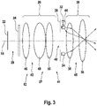
- the detector unit 12 and its beam path are shown schematically, with a presentation lighting that is also shown being explained as an example. However, such a staging lighting could also be arranged on the LIDAR emitter 10 .
- the LIDAR detector 22 is designed as a matrix detector.
- This matrix detector can be designed in particular as a solid-state detector and a CCD chip, a CMOS detector or have a similar chip.
- the LIDAR detector 22 is followed in axial succession by a bandpass filter 24, an optical device 26, a diaphragm 28 and a lens 30.
- a light source 32 and a light guide ring 34 are also arranged between the diaphragm 28 and the lens 30 .
- the light source 32 and the light guide ring 34 are arranged between the LIDAR detector 22 and the objective 30, which is formed by two different optical lenses 36, 38.
- the laser beam is guided from the lenses 36, 38 to the LIDAR detector 22 within a space 37.
- FIG. This space 37 is divided into a detection space 39 and an illumination space 41 by the bandpass filter 24 .
- said space 37 is divided by the diaphragm 28 into a rear diaphragm space 43 with the LIDAR detector 22 and a front diaphragm space 45 without the LIDAR detector 22 .
- the lens 30, the light source 32 and the light guide ring 34 are arranged in the pre-aperture space.
- the optics device 26 and the bandpass filter 24 are arranged in the rear space 43 of the diaphragm. At least most of the visible light from the light source 32 can be guided out of the pre-aperture space 45 through the lens 38 .
- the light from the light source 32 is introduced into the light guide ring 34, which can only be seen with its cross-sectional area in the lateral section.
- the light source 32 is radially outside of the light guide ring 34 arranged.
- the light source 32 and the light guide ring 34 are arranged adjacent to one another in a common plane.
- the light guide ring 34 is arranged in the direction of the optical axis 18 towards the lens 30 and offset to the diaphragm 28 .
- the light guide ring 34 is arranged coaxially with an aperture 40 and is circular.
- the light guide ring 34 has on its side facing the diaphragm 28 prisms 44 which guide the visible light out of the light guide ring 34 forward out of the lens 30 so that the lens 30 appears luminous to outside observers of the motor vehicle.
- the detector unit 12 with its lens 30 in the LIDAR module 8 ( 2 ) integrated next to the lighting device 6 without breaking the design language.
- the detector unit 12 is integrated in such a way that at first glance it is perceived as an additional lighting device.
- the said staging lighting is created by means of the light source 32 and the light guide ring 34 .
- a further staging lighting is preferably also arranged in the area of the LIDAR emitter 10, so that this also fits into the design of a motor vehicle lighting for the outside observer.
- the optics device 26 has more lenses than the lens 30.
- the optics device 26 comprises three different lenses 46, 48, 50 in this exemplary embodiment, which in this respect between the diaphragm 28 and the bandpass filter 24 are arranged. Consequently, the laser beam incident on the optics 30 can be fed to the LIDAR detector 22 through the five optical lenses 38 , 36 , 50 , 48 , 46 , the diaphragm 28 and the bandpass filter 24 .
- the bandpass filter 24 is permeable for the laser beam.
- the wavelength of the laser beam is in the near-infrared light range, which is between 800 nm and 1500 nm.
- the bandpass filter 24 in this exemplary embodiment is transparent to such a wavelength. Restricting the permeability to this wavelength range prevents scattered light from the staging lighting from also being able to impinge on the LIDAR detector 22 . In this respect, the bandpass filter 24 is not transparent to visible radiation.
- the aperture 28 and the lens 30 are designed in such a way that as little light as possible from the light source 32 can pass through the aperture 40 to the LIDAR detector 22 .
- the aperture 28 and the lens 30 are preferably designed in such a way that no light at all from the light source 32 can pass through the aperture 40 to the LIDAR detector 22 .
- the bandpass filter 24 is arranged within the aperture 40 . Moreover, the band-pass filter 24 may be provided in place of the aperture 28. That is, the bandpass filter 24 is then either between the optical device 26 and the Lens 30 arranged or no optical device 26 is provided.
- the lens surfaces of the lenses of the objective 30 and/or the optics device 26 have an anti-reflection coating for optimized transmission of the laser beam, which prevents reflections of the laser beam. That is, as a result of the anti-reflection coating, radiation in the wavelength of the laser is reflected less at the surface of the lens in question. On the other hand, stronger reflection of the visible light from the light source or the staging lighting is desired.
- the antireflection coating of the relevant lens is designed in such a way that it has an antireflection effect selectively only for the wavelength of the laser beam and, on the other hand, has a reduced antireflection effect for the visible light Light, or in the range of the spectrum of the light source 32 has.
- the lenses 46, 48, 50 which are on the side of the light source 32 axially facing the LIDAR detector 22, with an inexpensive anti-reflection coating, which also has a reduced anti-reflection effect for visible light
- the lenses 36 , 38 which are on the axially opposite side of the light source from the LIDAR detector 22, have no anti-reflection coating at all.
- these lenses would be the lenses 36, 38 of the objective 30, whereas the lenses 46, 48, 50 of the optical device 26 have an anti-reflection coating which reduces reflection for both laser beams and visible light.
- only the outermost lens 38 has no anti-reflection coating.
- only the outermost lens 38 has an anti-reflective coating that reflects visible light more than the laser beam, and the anti-reflective coating transmits the laser beam better than if no anti-reflective coating were present.
- the light source 32 is arranged next to or directly behind the outermost lens 38 that closes off the objective 30 . In this respect, the light source 32 can be provided outside the lens or even outside the detector unit 12 .
- the diaphragm 28 is designed with a reflecting or mirroring surface on its side facing away from the LIDAR detector 22 .
- the side of the diaphragm facing the LIDAR detector 22, on the other hand, is black in order to absorb scattered light and marginal rays that would otherwise impair the imaging quality of the lens. Further screens can be provided between the screen 28 and the LIDAR detector 22, which screens have black surfaces on both sides for the reason mentioned above.
- FIG. 12 shows an embodiment in which the diaphragm 28 is arranged very close to the immediately adjacent lens 136 of the objective 130.
- FIG. In contrast to the embodiment according to 3 no fiber optic ring is provided.
- Light source 132 lags relative to light source 132 3 a relatively large beam angle ⁇ with a light cone axis that is almost perpendicular to the optical axis 18 is.
- visible light is thrown from the light source 132 both in the direction of the diaphragm 28 and in the direction of the outermost lens 38 .
- visible light from the outermost lens 38 is directed outwardly refracted such that the outermost lens 38 appears to the outside observer as part of a vehicle light.
- Part of the visible light directed outward is thrown directly from the light source 132 in the direction of the lens 38 .
- the visible light is reflected from a reflective and/or specular surface 144 of the bezel 28 to the outermost lens 38 .
- the staging lighting after 4 can support the low beam. However, legal requirements for the cut-off line and the overhead values mentioned above must be observed.
- the light source 132 is arranged behind the outermost lens 38 and is illuminated from above when the motor vehicle lighting device is installed.
- the light cone axis can cross the optical axis 18 .
- a light guide can also be used to support the low beam with the staging lighting Find application, however, in contrast to the fiber optic ring 3 is arranged exclusively above the optical axis 18 and is therefore located in the upper half of the lens 130 .
- the light source is arranged in such a way that the visible light that comes directly from the light source or is reflected by the surface of the diaphragm and is preferably radiated by the lens into the lower hemisphere in such a way that light primarily or exclusively enters the cut-off line is radiated. This ensures that hardly any light above the cut-off line affects the overhead values.
- the focal length of the lens 136 of the objective 130, which is closest to the aperture 28, is preferably greater than the distance between the light source 132 and the outermost lens 38. A virtual image of the light source 132 is therefore generated.
- the light source 132 is therefore arranged at such a great distance from the optical axis 18 that an uppermost marginal ray 52 emanating from the light source 132 is still deflected below the light-dark boundary by the outermost lens 38 .
- figure 5 12 shows an alternative embodiment in which the lenses 236, 238 of the objective 230 are enclosed in a tube 53 made of opaque plastic or metal, so that the lenses 236, 238 are covered in a non-transparent manner radially outwards and inwards.
- the pipe 53 is in the form of a tube executed, but could also be designed oval or square.
- the light source 232 has an area that is transparent to visible light and is designed as a recess 54 in the exemplary embodiment.
- the light source 232 is arranged outside the tube 53 in such a way that the visible light is radiated and/or guided through the transparent area 54 into a space inside the tube 53 . This space is formed by the pre-shutter space 45 .
- the illumination can be adapted to the specific requirements of the detector unit 212 by appropriate configuration of a light transmission cross section of the transparent area 54 .
- the beam angle ⁇ of the light source 232 can be limited to the outermost lens 238 .
- the transparent area 54 is designed as an opening that runs obliquely in a wall of the tube 53 . Starting from the outside, this inclined recess runs in the direction of the front end of the tube 53 or in the direction of the lens 238.
- the transparent area in the tube 53 is preferably designed such that only the outermost lens 238 is illuminated, but not the lens 236 that is closer to the diaphragm 28.
- the light source 232 emits the visible light at a defined irradiation angle ⁇ , which is acute and which is confined between a light cone axis 258 of the light source 232 and the optical axis 18 .
- the irradiation angle ⁇ is so small that its apex in front of the outermost lens 238 and consequently lies outside the lens 230 .
- an inner wall 60 of an opening channel of the transparent area 54 can be made absorbing or reflecting for visible light, depending on the requirement.
- the lens 236 of the objective 230 immediately adjacent to the diaphragm 28 is designed as a meniscus lens.
- the two lenses 236, 238 of the objective 230 have different outer diameters.
- the outer lens 238 has a larger outside diameter than the meniscus lens.
- the tube 53 has different inner diameters on its inner surface 70 .
- a meniscus lens is provided.
- the irradiation angle ⁇ is not acute. Instead, the irradiation angle ⁇ is preferably at least about 90°.
- the associated vertex lies within the optics 330.
- the cone axis 358 of the light cone with the emission angle ⁇ is therefore aligned perpendicular to the optical axis 18.
- the light source 332 radiates visible light into the meniscus lens through the transparent area 354 of the tube 353 on the lateral surface 62 or lens side surface of the meniscus lens.
- the aperture 28 facing surface 64 of Meniscus lens has a smaller radius of curvature R1 than the opposite surface 66 of the meniscus lens.
- the light radiated in by the light source 332 is totally reflected at the interface of the surface 64 with the smaller radius of curvature R1 to the air and is thus deflected in the direction of the outer lens 338 .
- the visible light in the embodiment after 6 in contrast to the previous exemplary embodiment the light source 332 does not radiate directly into the outermost lens 338 . Instead, the light is redirected to the outermost lens 338 via another component of the lens 330 .
Landscapes
- Engineering & Computer Science (AREA)
- Physics & Mathematics (AREA)
- General Engineering & Computer Science (AREA)
- Computer Networks & Wireless Communication (AREA)
- General Physics & Mathematics (AREA)
- Radar, Positioning & Navigation (AREA)
- Remote Sensing (AREA)
- Microelectronics & Electronic Packaging (AREA)
- Optics & Photonics (AREA)
- Electromagnetism (AREA)
- Optical Radar Systems And Details Thereof (AREA)
Applications Claiming Priority (1)
| Application Number | Priority Date | Filing Date | Title |
|---|---|---|---|
| DE102021115721.8A DE102021115721A1 (de) | 2021-06-17 | 2021-06-17 | Kraftfahrzeugbeleuchtungseinrichtung |
Publications (1)
| Publication Number | Publication Date |
|---|---|
| EP4105683A1 true EP4105683A1 (fr) | 2022-12-21 |
Family
ID=82308434
Family Applications (1)
| Application Number | Title | Priority Date | Filing Date |
|---|---|---|---|
| EP22179497.7A Pending EP4105683A1 (fr) | 2021-06-17 | 2022-06-17 | Dispositif d'éclairage de véhicule automobile |
Country Status (3)
| Country | Link |
|---|---|
| EP (1) | EP4105683A1 (fr) |
| CN (1) | CN115493119A (fr) |
| DE (1) | DE102021115721A1 (fr) |
Citations (3)
| Publication number | Priority date | Publication date | Assignee | Title |
|---|---|---|---|---|
| DE19731754A1 (de) * | 1997-07-23 | 1999-02-04 | Spies Martin Dipl Ing Fh | Kombination Scheinwerfer Abstandssensor für Fahrzeuge |
| DE102017109905A1 (de) | 2017-05-09 | 2018-11-15 | Automotive Lighting Reutlingen Gmbh | Scheinwerfer mit integriertem Lidar |
| EP3438697A1 (fr) * | 2017-08-03 | 2019-02-06 | Automotive Lighting Reutlingen GmbH | Ensemble phare du véhicule automobile |
Family Cites Families (2)
| Publication number | Priority date | Publication date | Assignee | Title |
|---|---|---|---|---|
| DE102017222614A1 (de) | 2017-12-13 | 2019-06-13 | Robert Bosch Gmbh | Vorrichtung zur Umgebungserfassung sowie Verfahren zu dessen Betrieb |
| DE102018207293A1 (de) | 2018-05-09 | 2019-11-14 | Ibeo Automotive Systems GmbH | LIDAR Messsystem und Verfahren zur Montage eines LIDAR Messsystems |
-
2021
- 2021-06-17 DE DE102021115721.8A patent/DE102021115721A1/de active Pending
-
2022
- 2022-06-16 CN CN202210682884.8A patent/CN115493119A/zh active Pending
- 2022-06-17 EP EP22179497.7A patent/EP4105683A1/fr active Pending
Patent Citations (3)
| Publication number | Priority date | Publication date | Assignee | Title |
|---|---|---|---|---|
| DE19731754A1 (de) * | 1997-07-23 | 1999-02-04 | Spies Martin Dipl Ing Fh | Kombination Scheinwerfer Abstandssensor für Fahrzeuge |
| DE102017109905A1 (de) | 2017-05-09 | 2018-11-15 | Automotive Lighting Reutlingen Gmbh | Scheinwerfer mit integriertem Lidar |
| EP3438697A1 (fr) * | 2017-08-03 | 2019-02-06 | Automotive Lighting Reutlingen GmbH | Ensemble phare du véhicule automobile |
Also Published As
| Publication number | Publication date |
|---|---|
| DE102021115721A1 (de) | 2022-12-22 |
| CN115493119A (zh) | 2022-12-20 |
Similar Documents
| Publication | Publication Date | Title |
|---|---|---|
| EP2799761B1 (fr) | Module d'éclairage de phare de véhicule automobile | |
| DE4317772C2 (de) | Blendlichtsensor für Fahrzeuge | |
| DE60206369T2 (de) | Belichtungs- regensensor- erleuchtungs- positionierungsanlage | |
| DE102017105888A1 (de) | Lichtmodul für einen Kraftfahrzeugscheinwerfer und Scheinwerfer mit einem solchen Lichtmodul | |
| DE102008044003A1 (de) | Kameramodul mit Mehrfachfunktion | |
| DE102014203335A1 (de) | Lichtmodul eines Kraftfahrzeugscheinwerfers und Scheinwerfer mit einem solchen Lichtmodul | |
| DE102017109905A1 (de) | Scheinwerfer mit integriertem Lidar | |
| DE102013203925A1 (de) | Steuersystem für Fahrzeugscheinwerfer | |
| DE102018118584A1 (de) | Fahrzeugscheinwerfer mit LIDAR-Modul | |
| DE102017117591A1 (de) | Kraftfahrzeugscheinwerferanordnung | |
| DE102012011847A1 (de) | Nachtsichtsystem für ein Kraftfahrzeug | |
| DE102009054101A1 (de) | Beleuchtungsvorrichtung für ein Fahrzeug | |
| DE102019131155A1 (de) | Lidar-integrierte beleuchtungsvorrichtung für ein fahrzeug | |
| EP3077255B1 (fr) | Éclairage destiné à détecter des gouttes de pluie sur une vitre au moyen d'une caméra | |
| DE102009008418A1 (de) | Beleuchtungsvorrichtung mit einer IR-LED-Lichtquelle | |
| DE102004052667B4 (de) | Kraftfahrzeug mit einem Spurwechselassistenzsystem | |
| EP4105683A1 (fr) | Dispositif d'éclairage de véhicule automobile | |
| DE202017102056U1 (de) | Kraftfahrzeugscheinwerferanordnung und Steuergerät dafür | |
| DE4420889B4 (de) | Beleuchtungsvorrichtung für Fahrzeuge | |
| DE102019206379B4 (de) | Beleuchtungsvorrichtung mit einem als Lichtleiter ausgebildeten flächigen Trägermedium | |
| DE102018114389A1 (de) | Laserscanner für ein Fahrunterstützungssystem und Fahrunterstützungssystem aufweisend einen Laserscanner | |
| DE19916843A1 (de) | Leuchte für Kraftfahrzeuge | |
| DE102017103402A1 (de) | Beleuchtungseinrichtung zum Einbau in ein Kraftfahrzeug | |
| WO2017211647A1 (fr) | Dispositif et procédé pour projeter un motif lumineux | |
| DE102010054239B4 (de) | Infrarotscheinwerfer mit versteckter Infrarotstrahlungsquelle |
Legal Events
| Date | Code | Title | Description |
|---|---|---|---|
| PUAI | Public reference made under article 153(3) epc to a published international application that has entered the european phase |
Free format text: ORIGINAL CODE: 0009012 |
|
| STAA | Information on the status of an ep patent application or granted ep patent |
Free format text: STATUS: THE APPLICATION HAS BEEN PUBLISHED |
|
| AK | Designated contracting states |
Kind code of ref document: A1 Designated state(s): AL AT BE BG CH CY CZ DE DK EE ES FI FR GB GR HR HU IE IS IT LI LT LU LV MC MK MT NL NO PL PT RO RS SE SI SK SM TR |
|
| STAA | Information on the status of an ep patent application or granted ep patent |
Free format text: STATUS: REQUEST FOR EXAMINATION WAS MADE |
|
| 17P | Request for examination filed |
Effective date: 20230619 |
|
| RBV | Designated contracting states (corrected) |
Designated state(s): AL AT BE BG CH CY CZ DE DK EE ES FI FR GB GR HR HU IE IS IT LI LT LU LV MC MK MT NL NO PL PT RO RS SE SI SK SM TR |
|
| RAP3 | Party data changed (applicant data changed or rights of an application transferred) |
Owner name: MARELLI GERMANY GMBH |
|
| STAA | Information on the status of an ep patent application or granted ep patent |
Free format text: STATUS: EXAMINATION IS IN PROGRESS |
|
| 17Q | First examination report despatched |
Effective date: 20251219 |