EP4106038A1 - Cale pour coucheuse à filière, coucheuse à filière la comprenant et batterie secondaire au lithium comprenant une cathode fabriquée à l'aide de celle-ci - Google Patents
Cale pour coucheuse à filière, coucheuse à filière la comprenant et batterie secondaire au lithium comprenant une cathode fabriquée à l'aide de celle-ci Download PDFInfo
- Publication number
- EP4106038A1 EP4106038A1 EP21889415.2A EP21889415A EP4106038A1 EP 4106038 A1 EP4106038 A1 EP 4106038A1 EP 21889415 A EP21889415 A EP 21889415A EP 4106038 A1 EP4106038 A1 EP 4106038A1
- Authority
- EP
- European Patent Office
- Prior art keywords
- slurry
- die coater
- shim
- guides
- positive electrode
- Prior art date
- Legal status (The legal status is an assumption and is not a legal conclusion. Google has not performed a legal analysis and makes no representation as to the accuracy of the status listed.)
- Granted
Links
Images




Classifications
-
- H—ELECTRICITY
- H01—ELECTRIC ELEMENTS
- H01M—PROCESSES OR MEANS, e.g. BATTERIES, FOR THE DIRECT CONVERSION OF CHEMICAL ENERGY INTO ELECTRICAL ENERGY
- H01M4/00—Electrodes
- H01M4/02—Electrodes composed of, or comprising, active material
- H01M4/04—Processes of manufacture in general
- H01M4/0402—Methods of deposition of the material
- H01M4/0404—Methods of deposition of the material by coating on electrode collectors
-
- B—PERFORMING OPERATIONS; TRANSPORTING
- B05—SPRAYING OR ATOMISING IN GENERAL; APPLYING FLUENT MATERIALS TO SURFACES, IN GENERAL
- B05C—APPARATUS FOR APPLYING FLUENT MATERIALS TO SURFACES, IN GENERAL
- B05C5/00—Apparatus in which liquid or other fluent material is projected, poured or allowed to flow on to the surface of the work
- B05C5/02—Apparatus in which liquid or other fluent material is projected, poured or allowed to flow on to the surface of the work the liquid or other fluent material being discharged through an outlet orifice by pressure, e.g. from an outlet device in contact or almost in contact, with the work
- B05C5/0254—Coating heads with slot-shaped outlet
-
- H—ELECTRICITY
- H01—ELECTRIC ELEMENTS
- H01M—PROCESSES OR MEANS, e.g. BATTERIES, FOR THE DIRECT CONVERSION OF CHEMICAL ENERGY INTO ELECTRICAL ENERGY
- H01M10/00—Secondary cells; Manufacture thereof
- H01M10/05—Accumulators with non-aqueous electrolyte
- H01M10/052—Li-accumulators
-
- H—ELECTRICITY
- H01—ELECTRIC ELEMENTS
- H01M—PROCESSES OR MEANS, e.g. BATTERIES, FOR THE DIRECT CONVERSION OF CHEMICAL ENERGY INTO ELECTRICAL ENERGY
- H01M4/00—Electrodes
- H01M4/02—Electrodes composed of, or comprising, active material
- H01M4/13—Electrodes for accumulators with non-aqueous electrolyte, e.g. for lithium-accumulators; Processes of manufacture thereof
-
- H—ELECTRICITY
- H01—ELECTRIC ELEMENTS
- H01M—PROCESSES OR MEANS, e.g. BATTERIES, FOR THE DIRECT CONVERSION OF CHEMICAL ENERGY INTO ELECTRICAL ENERGY
- H01M4/00—Electrodes
- H01M4/02—Electrodes composed of, or comprising, active material
- H01M4/13—Electrodes for accumulators with non-aqueous electrolyte, e.g. for lithium-accumulators; Processes of manufacture thereof
- H01M4/139—Processes of manufacture
-
- B—PERFORMING OPERATIONS; TRANSPORTING
- B05—SPRAYING OR ATOMISING IN GENERAL; APPLYING FLUENT MATERIALS TO SURFACES, IN GENERAL
- B05C—APPARATUS FOR APPLYING FLUENT MATERIALS TO SURFACES, IN GENERAL
- B05C9/00—Apparatus or plant for applying liquid or other fluent material to surfaces by means not covered by any preceding group, or in which the means of applying the liquid or other fluent material is not important
- B05C9/06—Apparatus or plant for applying liquid or other fluent material to surfaces by means not covered by any preceding group, or in which the means of applying the liquid or other fluent material is not important for applying two different liquids or other fluent materials, or the same liquid or other fluent material twice, to the same side of the work
-
- H—ELECTRICITY
- H01—ELECTRIC ELEMENTS
- H01M—PROCESSES OR MEANS, e.g. BATTERIES, FOR THE DIRECT CONVERSION OF CHEMICAL ENERGY INTO ELECTRICAL ENERGY
- H01M10/00—Secondary cells; Manufacture thereof
- H01M10/05—Accumulators with non-aqueous electrolyte
- H01M10/058—Construction or manufacture
-
- Y—GENERAL TAGGING OF NEW TECHNOLOGICAL DEVELOPMENTS; GENERAL TAGGING OF CROSS-SECTIONAL TECHNOLOGIES SPANNING OVER SEVERAL SECTIONS OF THE IPC; TECHNICAL SUBJECTS COVERED BY FORMER USPC CROSS-REFERENCE ART COLLECTIONS [XRACs] AND DIGESTS
- Y02—TECHNOLOGIES OR APPLICATIONS FOR MITIGATION OR ADAPTATION AGAINST CLIMATE CHANGE
- Y02E—REDUCTION OF GREENHOUSE GAS [GHG] EMISSIONS, RELATED TO ENERGY GENERATION, TRANSMISSION OR DISTRIBUTION
- Y02E60/00—Enabling technologies; Technologies with a potential or indirect contribution to GHG emissions mitigation
- Y02E60/10—Energy storage using batteries
Definitions
- the present invention relates to a shim for a die coater, a die coater including the shim, and a lithium secondary battery including a positive electrode manufactured using the die coater.
- a secondary battery can be recharged and may be formed in a small size or as a large capacity. Accordingly, a lot of researches and developments secondary batteries are currently in progress. Such secondary batteries are manufactured as a form in which one battery cell is packed as a pack or tens of battery cells are connected as a pack, and are widely used for a mobile phone, a notebook computer, and a power source for driving a motor of an electric vehicle.
- An electrode of a secondary battery is manufactured by applying slurry, which is obtained by mixing an active material with a conductive agent, on a metal foil, drying and pressing the metal foil.
- a die coater for electrode production is equipment for applying slurry on a metal foil.
- a die coater is a device which supplies a fluid (slurry, an adhesive, a hard coating agent, ceramic, etc.) with fluidity to a space between upper die and lower die by using a pulseless pump or a piston pump, and coats the supplied fluid on an object such as a fabric, a film, a glass plate, or a sheet to have a constant thickness.
- a fluid slurry, an adhesive, a hard coating agent, ceramic, etc.
- FIG. 1 is an exploded perspective view showing a decomposition state of a conventional die coater for electrode production.
- a die coater 10 includes a supply port 15 through which a slurry is supplied to a slot die.
- the slurry supplied from a supply port 15 is moved into a body 11 having an inner space 14 which is connected to the supply port 15 and accommodates slurry.
- the body 11 includes an upper die 12, a lower die 13, and a shim 1 between the upper die 12 and the lower die 13.
- a discharge port 16 is prepared in the body 11 so that slurry may be discharged from the inner space 14 of the body 11 to the external side.
- the discharge port 16 has a thin and wide shape so that slurry may be widely coated on a metal foil.
- the slurry supplied from the supply port 15 is widely spread in a width direction of the discharge port 16 in the inner space of the body 11 and is then discharged through the discharge port 16. As such, a slurry can be coated on an electrode current collector.
- an aspect of the present invention provides a shim for a die coater capable of smoothly applying slurry on an edge portion, a die coater including the shim, and a lithium secondary battery including a positive electrode manufactured using the die coater.
- a shim for a die coater relates to a shim for a die coater which applies a slurry on an electrode current collector and includes: first and second guides having one end bent and extended; and a base which connects other ends of the first and second guides to each other. At this time, the first and second guides have a step along a discharge line of a slurry.
- the first and second guides have a step at a portion corresponding to 3/10 to 6/10 of an entire thickness of the first and second guides.
- an average thickness of regions where a step is not formed is in a range of 1 to 2 mm
- an average thickness of regions where a step is formed is in a range of 0.4 to 0.9 mm.
- the shim according to the present invention further includes at least one sub-guide which is located between the first and second guides and divides the discharge line.
- the sub-guide has a step along the discharge line of the slurry.
- the sub-guide may have a step at a portion corresponding to 3/10 to 6/10 of an entire thickness of the sub-guide, and in the sub-guide, an average thickness of regions where a step is not formed may be in a range of 1 to 2 mm, and an average thickness of regions where a step is formed may be in a range of 0.4 to 0.9 mm.
- the present invention provides a die coater including the above-described shim for a die coater.
- the die coater includes: a body which has an inner space for accommodating a slurry; a supply port through which the slurry is supplied to the inner space; and a discharge port through which the slurry is discharged from the inner space to an electrode current collector.
- the shim for the die coater may be detachably installed at the inner space of the die coater.
- a lithium secondary battery including a positive electrode manufactured by the above-described die coater.
- a lithium secondary battery according to the present invention includes: a positive electrode in which a positive electrode slurry is applied on a positive electrode current collector; a negative electrode in which a negative electrode slurry is applied on a negative electrode current collector; and a separator interposed between the positive electrode and the negative electrode.
- a thickness difference between a central portion of the positive electrode slurry and an edge portion of the positive electrode slurry along the cross-section in a width direction is 10% or more, and a thickness difference between a central portion of the negative electrode slurry and an edge portion of the negative electrode slurry along the cross-section in a width direction is 5% or less.
- a ratio of the thickness of the edge portion of the positive electrode slurry to the thickness of the central portion of the positive electrode slurry is in a range of 80 to 90%, and a ratio of the thickness of the edge portion of the positive electrode slurry to the thickness of the central portion of the negative electrode slurry is in a range of 95 to 105%.
- a shim for a die coater a die coater including the shim, and a lithium secondary battery including a positive electrode manufactured using the die coater of the present invention, it is possible to smoothly apply slurry on the edge portion.
- the present invention relates to a shim for a die coater, a die coater including the shim, and a lithium secondary battery including the positive electrode manufactured using the die coater.
- the inventors of the present invention invented a shim for a die coater capable of reducing a NP ratio reversal phenomenon, a die coater including the shim, and a lithium secondary battery including the positive electrode manufactured using the die coater, by controlling the length, shape, etc. of the coating boundary surface of slurry at the time of manufacturing an electrode.
- the guide of the shim for a die coater according to the present invention has a step on the boundary surface of the discharge line, through which slurry is discharged, to thereby allow slurry to be smoothly applied on the edge portion of the electrode current collector.
- a shim for a die coater relates to a shim for a die coater which applies a slurry on an electrode current collector and includes: first and second guides having one end bent and extended; and a base which connects other ends of the first and second guides to each other. At this time, the first and second guides have a step along a discharge line of a slurry.
- a step is formed on the boundary surface of the discharge line in the first and second guides, and the step is formed on the inner surface of first and second guides contacting the slurry.
- the boundary surface of the discharge line are formed to be lower, compared to the entire thickness of the first and second guides. This is to smoothly apply slurry on an edge portion when coating slurry.
- a shim for a die coater according to the present invention has a plate shape. One side of the shim is opened, and the other side is closed. At this time, a slurry can be discharged through an opened region of the shim for a die coater. Further, the base can close the other end of the shim for a die coater by connecting other ends of the first and second guides to each other.
- the shim for a die coater according to the present invention is preferably made of a material having sealability except for an opened region as it also plays a role of a gasket which prevents leakage of slurry form the die coater.
- the first and second guides are installed at one side of the base to be spaced apart from each other and are directed in the same direction to be parallel to each other. Specifically, a region between the first and second guides is a region where slurry is discharged, and the first and second guides form the discharge line of slurry.
- the base connects other ends of the first and second guides to each other and is formed in a simple straight line form.
- the present invention is not limited thereto.
- the first and second guides have a step along a discharge line of a slurry.
- the first and second guides have a step on the boundary surface of the discharge line, and when slurry dischagres, the step is formed on the inner surface of the first and second guides contacting the slurry.
- the thickness of the boundary surfaces of the discharge line in the first and second guides with are set to be smaller than the entire thickness of the first and second guides. This is to smoothly apply an edge portion of slurry coated when coating slurry.
- the first and second guides have a step at a portion corresponding to 3/10 to 6/10 of an entire thickness of the first and second guides.
- the first and second guides have a step at a portion corresponding to 4/10 to 5/10 of an entire thickness of the first and second guides.
- an average thickness of regions where a step is not formed is in a range of 1 to 2 mm
- an average thickness of regions where a step is formed is in a range of 0.4 to 0.9 mm.
- an average thickness of regions where a step is not formed may be in a range of 1.4 to 1.8 mm, and an average thickness of regions where a step is formed may be in a range of 0.5 to 0.8 mm.
- an average thickness of regions where a step is not formed may be 1.6 mm, and an average thickness of regions where a step is formed may be in a range of 0.5 to 0.7 mm.
- the shim for a die coater according to the present invention can control the length and shape of the edge portion of the slurry coated on the electrode current collector by making (setting) the thickness of the boundary surface of the slurry discharge line of first and second guides.
- the shim according to the present invention further includes at least one sub-guide which is located between the first and second guides and divides the discharge line.
- the shim for a die coater according to the present invention includes n sub-guides, (n+1) discharge lines can be formed.
- 1 to 10 sub-guides may be included.
- 3 sub-guides may be included.
- the shim for a die coater according to the present invention may form 4 discharge lines.
- sub-guides are included between the first and second guides in order to alternately stripe-coating the coated part and the non-coated part at the time of coating slurry.
- the sub-guide has a step along a discharge line of a slurry.
- the sub-guide has a step formed on the boundary surface of the discharge line of slurry, and when slurry is discharged, the step is formed on the side surface of the sub-guide contacting the slurry.
- the thickness of the boundary surface of the discharge line is set to be smaller than the entire thickness of the sub-guide. This is to smoothly apply slurry on the edge portion when coating slurry as in the first and second guides.
- the sub-guide may have a step at a portion corresponding to 3/10 to 6/10 of an entire thickness of the sub-guide.
- the sub-guide may have a step at a portion corresponding to 4/10 to 5/10 of an entire thickness of the sub-guide.
- an average thickness of regions where a step is not formed is in a range of 1 to 2 mm
- an average thickness of regions where a step is formed is in a range of 0.4 to 0.9 mm.
- an average thickness of regions where a step is not formed may be in a range of 1.4 to 1.8 mm
- an average thickness of regions where a step is formed may be in a range of 0.5 to 0.8 mm.
- an average thickness of regions where a step is not formed may be 1.6 mm, and an average thickness of regions where a step is formed may be in a range of 0.5 to 0.7 mm.
- the thickness of the step of the sub-guide may correspond to the thickness of the step of the first and second guides.
- the present invention provides a die coater including the above-described shim for a die coater.
- the die coater includes: a body which has an inner space for accommodating a slurry; a supply port through which a slurry is supplied to the inner space; and a discharge port through which a slurry is discharged from the inner space to an electrode current collector.
- the shim for the die coater may be detachably installed at the inner space of the die coater.
- the body of the die coater includes an upper die and a lower die.
- the upper and lower dies have a symmetrical prismoid shape, and may be assembled as one surface of the upper and lower dies, which is the bottom surface of the prismoid, faces each other.
- the lower die may include a supply port through which a slurry is supplied from an external side.
- the slurry which is supplied from the external side through the supply port, may be stored in an inner space formed in the lower die.
- a shim for a die coater is interposed between the upper die and the lower die.
- the slurry discharge line is formed at the inside of the die coater as the upper die and the lower die are spaced apart from each other by the thickness of the shim for a die coater.
- slurry supplied from the supply port flows in the die coater along the discharge line and may be discharged to the outside through the discharge port.
- the shim for a die coater includes a first guide, a second guide, and a sub-guide where a step is formed along the discharge line, to thereby control the length and shape of the edge portion of the slurry. Since the first and second guides were explained above, the detailed description for the first and second guides is omitted here.
- the present invention provides a lithium secondary battery including the positive electrode manufactured by the above-described die coater.
- a lithium secondary battery according to the present invention includes: a positive electrode in which a positive electrode slurry is applied on a positive electrode current collector; the negative electrode in which the negative electrode slurry is applied on the negative electrode current collector; and a separator interposed between the positive electrode and the negative electrode.
- the positive electrode current collector may contain at least one of aluminum, nickel, and their alloys.
- the electrode current collector used for the positive electrode is a metal having high conductivity, and any metal which the positive electrode active material slurry may be easily attached to and which is not reactive in the voltage range of the electrochemical device can be used.
- the slurry of the mixture layer may contain a positive electrode active material.
- the positive electrode active material may be a lithium-containing oxide, and a transition metal oxide containing lithium may be used as the lithium-containing oxide.
- the positive electrode active material layer according to the present invention includes an active material component represented by Chemical Formula 1 below.
- the value a is 0.6 or more, specifically 0.8 or more. In the Formula 1, as the value a increases, the value b and/or value c decrease within the range satisfying the above Formula 1.
- the negative electrode current collector may contain at least one of copper, gold, nickel, and their alloys.
- the electrode current collector may be made of copper.
- the slurry of the mixture layer may contain the negative electrode active material.
- the negative electrode active material may include a carbon material, lithium metal, silicon or tin. When a carbon material is used as the negative electrode active material, both low crystalline carbon and high crystalline carbon may be used. Representative examples of low crystalline carbon include soft carbon and hard carbon.
- high crystalline carbon include natural graphite, Kish graphite, pyrolytic carbon, mesophase pitch based carbon fiber, mesocarbon microbeads, mesophase pitches, and high-temperature calcined carbons such as petroleum or coal tar pitch derived cokes.
- the slurry may include a conductive material and a binder which are commonly used in the related field.
- the separator may be made of any porous substrate used in a lithium secondary battery, and for example, a polyolefin-based porous membrane or a nonwoven fabric may be used, but the present invention is not particularly limited thereto.
- polystyrene-based porous membrane examples include polyethylene such as high density polyethylene, linear low density polyethylene, low density polyethylene, or ultrahigh molecular weight polyethylene, and polyolefin-based polymers, such as polypropylene, polybutylene, or polypentene, which is used alone or in a mixture thereof to form a membrane .
- polyethylene such as high density polyethylene, linear low density polyethylene, low density polyethylene, or ultrahigh molecular weight polyethylene
- polyolefin-based polymers such as polypropylene, polybutylene, or polypentene, which is used alone or in a mixture thereof to form a membrane .
- Polyethyleneterephthalate, polybutyleneterephthalate, polyester, polyacetal, polyamide, polycarbonate, polyimide, polyetheretherketone, polyethersulfone, polyphenyleneoxide, polyphenylenesulfide, and polyethylenenaphthalene, etc. may be used individually or as a polymer by a mixture thereof, to thereby form the non-woven fabric, in addition to polyolefin-based nonwoven fabric.
- a thickness difference between a central portion of the positive electrode slurry and an edge portion of the positive electrode slurry along the cross- section in the width direction is 10% or more, and a thickness difference between a central portion of the negative electrode slurry and an edge portion of the negative electrode slurry along the cross-section in the width direction is 5% or less.
- a ratio of the thickness of the edge portion of the positive electrode slurry to the thickness of the central portion of the positive electrode slurry may be in a range of 80 to 90%, and a ratio of the thickness of the edge portion of the positive electrode slurry to the thickness of the central portion of the negative electrode slurry may be in a range of 95 to 105%.
- a lithium secondary battery manufactured according to the present invention it is possible to control the length and shape of the edge region of slurry coated on a positive electrode current collector. As such, the NP ratio reversal risk, etc. can be reduced by increasing the length of the coating boundary surface of slurry.
- FIG. 2 is a schematic diagram of a shim for a die coater according to one embodiment of the present invention.
- a shim 100 for a die coater according to the present invention relates to a shim for a die coater which applies a slurry on an electrode current collector and includes: first and second guides 110 and 120 having one end bent and extended; and a base 130 which connects other ends of the first and second guides 110 and 120 to each other.
- the shim 100 for a die coater has a plate shape. One side of the shim 100 is opened, and the other side is closed. At this time, a slurry can be discharged through an opened region of the shim 100 for a die coater. Further, the base 130 can close the other end of the shim 100 for a die coater by connecting other ends of the first and second guides 110 and 120 to each other. Further, the shim 100 for a die coater is preferably made of a material having sealability except for an opened region as it also plays a role of a gasket which prevents leakage of slurry from the die coater.
- the first and second guides 110 and 120 are installed at one side of the base 130 to be spaced apart from each other and are directed in the same direction to be parallel to each other. Specifically, a region between the first and second guides 110 and 120 is a region where slurry is discharged, and the first and second guides 110 and 120 form the discharge line of slurry.
- the base 130 connects other ends of the first and second guides 110 and 120 to each other and is formed in a simple straight line form.
- the present invention is not limited thereto.
- first and second guides 110 and 12 have a step 140 along a discharge line of a slurry.
- first and second guides 110 and 120 have a step 140 on the boundary surface of the discharge line, and when slurry is discharged, the step 140 is formed on the inner surface of the first and second guides 110 and 120 contacting the slurry.
- the thickness of boundary surface of the discharge line is set to be smaller than the entire thickness of the first and second guides 110 and 120. This is to smoothly apply slurry on an edge portion when coating slurry.
- the first and second guides 110 and 120 have a step 140 at a portion corresponding to 3/10 to 6/10 of an entire thickness of the first and second guides 110 and 120.
- an average thickness of regions where a step 130 is not formed is 1.5 mm
- an average thickness of regions where a step 140 is formed is 0.7 mm.
- the present invention is not limited thereto.
- the shim 100 for a die coater can control the length and shape of the edge portion of the slurry coated on the electrode current collector by making (setting) the thickness of the boundary surface of the slurry discharge line of first and second guides 110 and 120.
- the NP ratio reversal risk, etc. can be reduced by increasing the length of the coating boundary surface of slurry.
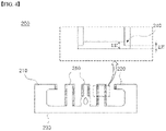
- FIGS. 3 to 4 are schematic diagrams of a shim for a die coater according to another embodiment of the present invention.
- the shim 200 for the die coater according to the present invention includes at least one sub-guide 250 which is located between the first and second guides 210 and 220 and divides the discharge line. It is illustrated that there are 3 sub-guides 250, but the present invention is not limited to this example. If 3 sub-guides 250 are included between the first and second guides 210 and 220, the shim 200 for a die coater according to the present invention may form 4 discharge lines.
- sub-guides 250 are included between the first and second guides 210 and 220 in order to alternately stripe-coating the coated part and the non-coated part at the time of coating slurry.
- the sub-guide 250 has a step 240 along the discharge line of the slurry.
- the sub-guide 250 has a step 240 formed on the boundary surface of the discharge line of slurry, and when slurry is discharged, the step 240 is formed on the side surface of the sub-guide 250 contacting the slurry.
- the thickness of the boundary surface of the discharge line is set to be smaller than the entire thickness of the sub-guide 250. This is to smoothly apply slurry on the edge portion when coating slurry as in the first and second guides 210 and 220.
- the sub-guide 250 has a step 240 at a portion corresponding to 3/10 to 6/10 of an entire thickness of the sub-guide 250.
- an average thickness of regions where a step 240 is not formed is 1.5 mm
- an average thickness of regions where a step 240 is formed is 0.7 mm.
- the present invention is not limited thereto. Since the first and second guides 210 and 220 were explained above, the detailed description for the first and second guides 210 and 220 is omitted here.
- the sub-guide 250 of the shim 200 for a die coater according to the present invention can control the length and shape of the edge portion of the slurry coated on the electrode current collector by making the thickness of the boundary surface of the slurry discharge line.
- the NP ratio reversal risk, etc. can be reduced by increasing the length of the coating boundary surface of slurry.
- FIG. 5 is an exploded perspective view of a die coater according to one embodiment of the present invention.
- a die coater 30 according to the present invention includes: a body 31 which has an inner space for accommodating a slurry; a supply port 35 through which a slurry is supplied to the inner space 34; and a discharge port 36 through which a slurry is discharged from the inner space 34 to an electrode current collector.
- the shim 300 for the die coater may be detachably installed at the inner space of the die coater 30.
- the body 31 of the die coater 30 includes an upper die 32 and a lower die 33.
- the upper and lower dies 32 and 33 have a symmetrical prismoid shape, and may be assembled as one surface of the upper and lower dies 32 and 33, which is the bottom surface of the prismoid, faces each other.
- the lower die 33 may include a supply port 35 through which a slurry is supplied from an external side.
- the slurry, which is supplied from the external side through the supply port 35, may be stored in an inner space 34 formed in the lower die 33.
- a shim 300 for a die coater is interposed between the upper die 32 and the lower die 33.
- the slurry discharge line is formed at the inside of the die coater 30 as the upper die 32 and the lower die 33 are spaced apart from each other by the thickness of the shim 300 for a die coater. Slurry supplied from the supply port 35 flows in the die coater along the discharge line and is discharged to the outside through the discharge port 36.
- the shim 300 for a die coater includes a first guide 310, a second guide 320, and a sub-guide 350 where a step 340 is formed along the discharge line, to thereby control the length and shape of the edge portion of the slurry. Since the first and second guides 310 and 320 were explained above, the detailed description for the first and second guides 310 and 320 is omitted here.
- a positive electrode was manufactured using the die coater of FIG. 5 (example 1). Specifically, slurry was applied on an aluminum current collector by supplying positive electrode slurry to a die coater, and the slurry was applied on the top surface and the back surface of the aluminum current collector. Further, as a comparative example, a positive electrode was manufactured using a die coater including the shim 10 for a die coater of FIG. 6 in the same manner as in example 1 (comparative example 1).
- FIG. 7 is a graph showing the thickness of the slurry by positions of the positive electrode manufactured according to Example 1 and in Comparative Example 1. Referring to FIG. 7 , in the case of the example 1, the thickness of slurry decreases toward the edge region of the positive electrode. Particularly, in the example 1, the side ring phenomenon of the back surface was improved, compared to the comparative example 1.
- the sliding length of a die coater, to which a shim for a die coater according to the present invention has been applied was about 5 to 6 mm. It is seen that the sliding length has been improved by smoothly coating slurry on the edge portion of the current collector.
- lane (left) and lane (right) mean the left edge region and the right edge region of slurry coated in a stripe form.
- the sliding length was about 2 to 3 mm.
- the top surface of the comparative example 1 is in a level in which the NP ratio is reversed, and it is predicted that the swelling of the thickness according to the NP ratio reversal will occur.
- a positive electrode was manufactured in the same manner as in the example 1 except that the type and composition of the positive electrode slurry were set to be different from those of the example 1. And the result is shown in Table 2.
- Table 2 Sliding 1 st lane (left) 1 st lane (right ) 2 nd lane (left) 2 nd lane (right ) 3 rd lane (left) 3 rd lane (right ) 4 th lane (left) 4 th lane (right ) Aver age Exam ple 2 Top 6.45 5.96 5.04 5.24 5.64 4.95 5.60 5.90 5.55 Back 7.12 5.73 4.84 6.72 6.16 6.95 6.76 6.36 6.33 Exam ple 3 Top 5.70 5.80 6.07 5.76 5.37 4.97 5.69 5.89 5.62 Back 5.76 5.07 5.63 5.63 6.00 7.20 7.97 4.88 6.18 Exam ple 4 Top 5.86 6.15 4.88 6.18 4.86 5.65 4.99 7.13 5.51 Back 7.02 5.44 5.16 5.36 5.65 5.84 6.95 5.86
- the sliding length has been improved to a 5 to 6 mm level from a 2 to 3 mm level.
- the NP ratio reversal risk, etc. can be reduced by increasing the length of the coating boundary surface of slurry.
Landscapes
- Chemical & Material Sciences (AREA)
- Engineering & Computer Science (AREA)
- Chemical Kinetics & Catalysis (AREA)
- Electrochemistry (AREA)
- General Chemical & Material Sciences (AREA)
- Manufacturing & Machinery (AREA)
- Materials Engineering (AREA)
- Battery Electrode And Active Subsutance (AREA)
- Coating Apparatus (AREA)
Applications Claiming Priority (2)
| Application Number | Priority Date | Filing Date | Title |
|---|---|---|---|
| KR1020200145292A KR20220059744A (ko) | 2020-11-03 | 2020-11-03 | 다이 코터용 심, 이를 포함하는 다이 코터 및 이를 이용하여 제조된 양극을 포함하는 리튬 이차전지 |
| PCT/KR2021/014271 WO2022097950A1 (fr) | 2020-11-03 | 2021-10-14 | Cale pour coucheuse à filière, coucheuse à filière la comprenant et batterie secondaire au lithium comprenant une cathode fabriquée à l'aide de celle-ci |
Publications (3)
| Publication Number | Publication Date |
|---|---|
| EP4106038A1 true EP4106038A1 (fr) | 2022-12-21 |
| EP4106038A4 EP4106038A4 (fr) | 2024-07-31 |
| EP4106038B1 EP4106038B1 (fr) | 2026-03-25 |
Family
ID=81457171
Family Applications (1)
| Application Number | Title | Priority Date | Filing Date |
|---|---|---|---|
| EP21889415.2A Active EP4106038B1 (fr) | 2020-11-03 | 2021-10-14 | Cale pour coucheuse à filière, coucheuse à filière la comprenant et batterie secondaire au lithium comprenant une cathode fabriquée à l'aide de celle-ci |
Country Status (5)
| Country | Link |
|---|---|
| US (1) | US12551918B2 (fr) |
| EP (1) | EP4106038B1 (fr) |
| KR (1) | KR20220059744A (fr) |
| CN (1) | CN115298849A (fr) |
| WO (1) | WO2022097950A1 (fr) |
Families Citing this family (8)
| Publication number | Priority date | Publication date | Assignee | Title |
|---|---|---|---|---|
| KR102865379B1 (ko) * | 2021-11-12 | 2025-09-25 | 주식회사 엘지에너지솔루션 | 전극 코팅 장치 및 전극 코팅 방법 |
| JP7739438B2 (ja) * | 2021-12-08 | 2025-09-16 | エルジー エナジー ソリューション リミテッド | スロットダイシムおよびそれを含むスロットダイ |
| EP4279184A1 (fr) | 2022-05-19 | 2023-11-22 | LG Energy Solution, Ltd. | Système de dépôt d'une matière |
| US20250196176A1 (en) * | 2022-12-09 | 2025-06-19 | Lg Energy Solution, Ltd. | Shim Plate and Slot Die Coater Including the Same |
| CN115970988B (zh) * | 2022-12-15 | 2024-02-09 | 苏州擎动动力科技有限公司 | 一种涂布装置和系统 |
| CN222855817U (zh) * | 2024-04-15 | 2025-05-13 | 宁德时代新能源科技股份有限公司 | 一种涂布设备和涂布系统 |
| CN118367228A (zh) * | 2024-06-20 | 2024-07-19 | 西北工业大学 | 一种快充长循环硅基锂离子电池的制备方法及循环充电方法 |
| KR20260037966A (ko) * | 2024-09-11 | 2026-03-18 | 주식회사 엘지에너지솔루션 | 심 플레이트 및 이를 포함하는 슬롯 다이 코터 |
Family Cites Families (39)
| Publication number | Priority date | Publication date | Assignee | Title |
|---|---|---|---|---|
| US7097673B2 (en) * | 2001-06-07 | 2006-08-29 | 3M Innovative Properties Company | Coating edge control |
| JP2006255643A (ja) * | 2005-03-18 | 2006-09-28 | Hitachi Chem Co Ltd | 塗工機及びそれを用いた塗工方法 |
| KR101265212B1 (ko) * | 2011-02-22 | 2013-05-24 | 삼성에스디아이 주식회사 | 이차전지 |
| CN105027347B (zh) | 2013-03-07 | 2018-01-05 | Nec 能源元器件株式会社 | 非水电解液二次电池 |
| JP2014188435A (ja) | 2013-03-27 | 2014-10-06 | Nitto Denko Corp | 塗布装置 |
| JP2014233651A (ja) * | 2013-05-31 | 2014-12-15 | オリジン電気株式会社 | 接着剤塗布装置及び方法 |
| CN104487176B (zh) * | 2013-07-16 | 2017-05-03 | Lg化学株式会社 | 狭缝式挤出涂布机用部件、狭缝式挤出涂布机用可动部件以及使用这些部件的电极生产用狭缝式挤出涂布机 |
| WO2015009033A1 (fr) | 2013-07-16 | 2015-01-22 | 주식회사 엘지화학 | Élément pour machine à enduire à filière plate, élément mobile pour machine à enduire à filière plate et machine à enduire à filière plate pour la production d'électrode les utilisant |
| KR101801422B1 (ko) | 2013-10-18 | 2017-11-24 | 주식회사 엘지화학 | 전극 생산용 슬롯 다이 코터 |
| JP2015136675A (ja) * | 2014-01-24 | 2015-07-30 | Necエナジーデバイス株式会社 | 塗工装置、塗工装置の組み立て方法、および二次電池用電極の製造方法 |
| KR101841346B1 (ko) | 2016-06-01 | 2018-03-22 | 고려대학교 산학협력단 | 비뉴튼성 코팅액의 균일 분포를 위한 슬롯 다이 내의 심 및 이를 포함하는 슬롯 다이 코터 |
| CN110198792B (zh) * | 2017-02-03 | 2021-10-26 | 日本汽车能源株式会社 | 涂敷模具、涂敷装置、涂敷方法以及二次电池的制造方法 |
| KR102227310B1 (ko) * | 2017-08-23 | 2021-03-15 | 주식회사 엘지화학 | 전극 제조용 슬롯 다이 |
| CN208173722U (zh) * | 2017-08-24 | 2018-11-30 | 日立汽车系统株式会社 | 二次电池 |
| CN207765534U (zh) * | 2018-02-09 | 2018-08-24 | 宁德新能源科技有限公司 | 用于涂布装置的垫片及涂布装置 |
| CN208127303U (zh) * | 2018-03-08 | 2018-11-20 | 成都市银隆新能源有限公司 | 一种挤压式涂布模头垫片 |
| KR102677503B1 (ko) | 2018-09-27 | 2024-06-20 | 주식회사 엘지에너지솔루션 | 슬롯들의 움직임으로 전극 활물질 슬러리의 코팅 형태가 변환되는 슬롯 다이 코터 |
| JP7155881B2 (ja) * | 2018-10-31 | 2022-10-19 | トヨタ自動車株式会社 | 電極板、これを用いた電池、電極板の製造方法、これを用いた電池の製造方法、ダイヘッド |
| CN113228338A (zh) | 2019-03-18 | 2021-08-06 | 株式会社大赛璐 | 浆料 |
| KR20200145292A (ko) | 2019-06-21 | 2020-12-30 | 탱커펀드주식회사 | 협업 필터링 기반의 사용자 선호도 예측 방법을 실행시키기 위한 프로그램이 기록된 컴퓨터로 판독 가능한 기록매체 |
| CN211026907U (zh) | 2019-09-23 | 2020-07-17 | 合肥国轩高科动力能源有限公司 | 一种可调式涂布模头垫片 |
| KR102866099B1 (ko) * | 2019-11-20 | 2025-09-26 | 삼성에스디아이 주식회사 | 이차전지 전극 제조용 슬롯다이 |
| JP7253147B2 (ja) * | 2019-11-26 | 2023-04-06 | トヨタ自動車株式会社 | 非水電解質二次電池 |
| CN211726368U (zh) * | 2019-11-29 | 2020-10-23 | 合肥国轩高科动力能源有限公司 | 一种边缘削薄的涂布模头垫片 |
| KR20210083512A (ko) | 2019-12-27 | 2021-07-07 | 주식회사 엘지에너지솔루션 | 코팅 균일성이 우수한 전극 슬러리 토출용 코팅 심 및 이를 포함하는 코팅 다이 |
| WO2021161649A1 (fr) * | 2020-02-12 | 2021-08-19 | パナソニック株式会社 | Matrice de revêtement et dispositif de revêtement |
| US20230140800A1 (en) * | 2020-10-28 | 2023-05-04 | Lg Energy Solution, Ltd. | Slot Die Coater |
| WO2022097985A1 (fr) * | 2020-11-05 | 2022-05-12 | 주식회사 엘지에너지솔루션 | Dispositif d'enduction à filière à fente |
| KR20220088069A (ko) * | 2020-12-18 | 2022-06-27 | 주식회사 엘지에너지솔루션 | 밀링 가공을 이용한 다이 코터용 심의 제조방법 |
| ES3040213T3 (en) * | 2021-11-26 | 2025-10-29 | Lg Energy Solution Ltd | Slot die coater |
| HUE071858T2 (hu) * | 2021-11-26 | 2025-09-28 | Lg Energy Solution Ltd | Résszerszám bevonatoló berendezés |
| KR102872643B1 (ko) * | 2021-11-29 | 2025-10-16 | 주식회사 엘지에너지솔루션 | 이차전지용 집전체에 활물질을 코팅하기 위한 다이 코터용 심 및 다이 코터 |
| JP7739438B2 (ja) * | 2021-12-08 | 2025-09-16 | エルジー エナジー ソリューション リミテッド | スロットダイシムおよびそれを含むスロットダイ |
| KR102864423B1 (ko) * | 2021-12-21 | 2025-09-24 | 주식회사 엘지에너지솔루션 | 슬롯 다이 코터 및 이를 포함하는 다레인 이중 코팅 장치 |
| KR102876795B1 (ko) * | 2022-01-11 | 2025-10-24 | 주식회사 엘지에너지솔루션 | 이차전지 집전체의 활물질 코팅을 위한 다이 코터 |
| KR20230108616A (ko) * | 2022-01-11 | 2023-07-18 | 주식회사 엘지에너지솔루션 | 이차전지 집전체의 활물질 코팅을 위한 다이 코터 |
| JP7510453B2 (ja) * | 2022-03-14 | 2024-07-03 | プライムプラネットエナジー&ソリューションズ株式会社 | 電池の製造方法 |
| KR20230140718A (ko) * | 2022-03-30 | 2023-10-10 | 주식회사 엘지에너지솔루션 | 이차전지 집전체의 활물질 코팅을 위한 다이 코터 |
| KR102630461B1 (ko) * | 2022-12-23 | 2024-01-31 | 주식회사 엘지에너지솔루션 | 리튬 이차전지용 음극 및 이의 제조방법 |
-
2020
- 2020-11-03 KR KR1020200145292A patent/KR20220059744A/ko active Pending
-
2021
- 2021-10-14 EP EP21889415.2A patent/EP4106038B1/fr active Active
- 2021-10-14 CN CN202180022605.9A patent/CN115298849A/zh active Pending
- 2021-10-14 US US17/913,343 patent/US12551918B2/en active Active
- 2021-10-14 WO PCT/KR2021/014271 patent/WO2022097950A1/fr not_active Ceased
Also Published As
| Publication number | Publication date |
|---|---|
| CN115298849A (zh) | 2022-11-04 |
| EP4106038A4 (fr) | 2024-07-31 |
| KR20220059744A (ko) | 2022-05-10 |
| WO2022097950A1 (fr) | 2022-05-12 |
| US12551918B2 (en) | 2026-02-17 |
| US20230149968A1 (en) | 2023-05-18 |
| EP4106038B1 (fr) | 2026-03-25 |
Similar Documents
| Publication | Publication Date | Title |
|---|---|---|
| EP4106038B1 (fr) | Cale pour coucheuse à filière, coucheuse à filière la comprenant et batterie secondaire au lithium comprenant une cathode fabriquée à l'aide de celle-ci | |
| JP7442541B2 (ja) | コーティングの均一性に優れた電極スラリー吐出用のコーティングシム及びそれを含むコーティングダイ | |
| US8323822B2 (en) | Power storage device with different electrolyte layers in stack | |
| KR102722956B1 (ko) | 이차전지용 음극 및 그를 포함하는 이차전지 | |
| KR20050011723A (ko) | 고체 전해질, 리튬 이온 전지 및 그의 제조 방법 | |
| EP3834950B1 (fr) | Filière à fente pour barre d'étranglement et appareil de revêtement de suspension comprenant celle-ci | |
| US5626729A (en) | Modified polymer electrodes for energy storage devices and method of making same | |
| KR102498353B1 (ko) | 리튬 이차전지용 전극 및 이를 포함하는 리튬 이차전지 | |
| KR20170111748A (ko) | 음극 활물질 슬러리, 이를 포함하는 음극, 상기 음극을 포함하는 리튬 이차전지 | |
| CN110741493B (zh) | 锂二次电池的负极及包括该负极的锂二次电池 | |
| EP3851491B1 (fr) | Composition et corps multicouche | |
| KR20230078497A (ko) | 오프셋 조정 가능한 심 및 이를 포함하는 슬롯 다이 코터 | |
| EP4492523A1 (fr) | Électrolyte composite, son procédé de préparation et batterie secondaire au lithium le comprenant | |
| EP3993089A1 (fr) | Procédé de fabrication d'électrode sur laquelle une couche de résistance est formée | |
| KR20180023620A (ko) | 리튬 이차전지용 음극 및 이의 제조방법 | |
| US20240299970A1 (en) | Slot Die Coater | |
| KR20220135643A (ko) | 활물질이 없는 전고체 전지용 음극 및 이를 포함하는 전고체 전지 | |
| EP4037057A1 (fr) | Électrolyte pour batterie au lithium métallique et batterie au lithium métallique le comprenant | |
| US20230178852A1 (en) | Method for manufacturing separator and separator obtained thereby | |
| EP4531128A1 (fr) | Électrode de batterie secondaire au lithium-ion et batterie secondaire au lithium-ion | |
| KR102892910B1 (ko) | 이차전지용 전극 제조 방법 및 장치 | |
| EP3460896B1 (fr) | Électrolyte polymère solide et batterie secondaire au lithium comprenant cet électrolyte | |
| KR20230033349A (ko) | 리튬 이차 전지용 음극, 이를 포함하는 이차 전지 및 이의 제조 방법 | |
| KR20220057166A (ko) | 다공성 지지층을 포함하는 바이폴라 전고체전지 | |
| US20250379249A1 (en) | Apparatus and method for pressurizing battery |
Legal Events
| Date | Code | Title | Description |
|---|---|---|---|
| STAA | Information on the status of an ep patent application or granted ep patent |
Free format text: STATUS: THE INTERNATIONAL PUBLICATION HAS BEEN MADE |
|
| PUAI | Public reference made under article 153(3) epc to a published international application that has entered the european phase |
Free format text: ORIGINAL CODE: 0009012 |
|
| STAA | Information on the status of an ep patent application or granted ep patent |
Free format text: STATUS: REQUEST FOR EXAMINATION WAS MADE |
|
| 17P | Request for examination filed |
Effective date: 20220914 |
|
| AK | Designated contracting states |
Kind code of ref document: A1 Designated state(s): AL AT BE BG CH CY CZ DE DK EE ES FI FR GB GR HR HU IE IS IT LI LT LU LV MC MK MT NL NO PL PT RO RS SE SI SK SM TR |
|
| DAV | Request for validation of the european patent (deleted) | ||
| DAX | Request for extension of the european patent (deleted) | ||
| A4 | Supplementary search report drawn up and despatched |
Effective date: 20240703 |
|
| RIC1 | Information provided on ipc code assigned before grant |
Ipc: B05C 9/06 20060101ALN20240627BHEP Ipc: H01M 10/058 20100101ALN20240627BHEP Ipc: B05C 5/02 20060101ALI20240627BHEP Ipc: H01M 10/052 20100101ALI20240627BHEP Ipc: H01M 4/13 20100101ALI20240627BHEP Ipc: H01M 4/04 20060101AFI20240627BHEP |
|
| STAA | Information on the status of an ep patent application or granted ep patent |
Free format text: STATUS: EXAMINATION IS IN PROGRESS |
|
| 17Q | First examination report despatched |
Effective date: 20250326 |
|
| GRAP | Despatch of communication of intention to grant a patent |
Free format text: ORIGINAL CODE: EPIDOSNIGR1 |
|
| STAA | Information on the status of an ep patent application or granted ep patent |
Free format text: STATUS: GRANT OF PATENT IS INTENDED |
|
| RIC1 | Information provided on ipc code assigned before grant |
Ipc: H01M 4/04 20060101AFI20251216BHEP Ipc: H01M 10/052 20100101ALI20251216BHEP Ipc: B05C 5/02 20060101ALI20251216BHEP Ipc: H01M 4/139 20100101ALI20251216BHEP Ipc: H01M 10/058 20100101ALN20251216BHEP Ipc: B05C 9/06 20060101ALN20251216BHEP |
|
| INTG | Intention to grant announced |
Effective date: 20260107 |
|
| GRAS | Grant fee paid |
Free format text: ORIGINAL CODE: EPIDOSNIGR3 |
|
| GRAA | (expected) grant |
Free format text: ORIGINAL CODE: 0009210 |
|
| STAA | Information on the status of an ep patent application or granted ep patent |
Free format text: STATUS: THE PATENT HAS BEEN GRANTED |
|
| P01 | Opt-out of the competence of the unified patent court (upc) registered |
Free format text: CASE NUMBER: UPC_APP_0003927_4106038/2026 Effective date: 20260203 |
|
| AK | Designated contracting states |
Kind code of ref document: B1 Designated state(s): AL AT BE BG CH CY CZ DE DK EE ES FI FR GB GR HR HU IE IS IT LI LT LU LV MC MK MT NL NO PL PT RO RS SE SI SK SM TR |
|
| REG | Reference to a national code |
Ref country code: CH Ref legal event code: F10 Free format text: ST27 STATUS EVENT CODE: U-0-0-F10-F00 (AS PROVIDED BY THE NATIONAL OFFICE) Effective date: 20260325 Ref country code: GB Ref legal event code: FG4D |
|
| REG | Reference to a national code |
Ref country code: DE Ref legal event code: R096 Ref document number: 602021050843 Country of ref document: DE |
|
| REG | Reference to a national code |
Ref country code: IE Ref legal event code: FG4D |