EP4106149B1 - Lagervorrichtung, und herstellungsverfahren - Google Patents
Lagervorrichtung, und herstellungsverfahren Download PDFInfo
- Publication number
- EP4106149B1 EP4106149B1 EP21753193.8A EP21753193A EP4106149B1 EP 4106149 B1 EP4106149 B1 EP 4106149B1 EP 21753193 A EP21753193 A EP 21753193A EP 4106149 B1 EP4106149 B1 EP 4106149B1
- Authority
- EP
- European Patent Office
- Prior art keywords
- ring
- magnetic
- magnetic ring
- stator
- coil
- Prior art date
- Legal status (The legal status is an assumption and is not a legal conclusion. Google has not performed a legal analysis and makes no representation as to the accuracy of the status listed.)
- Active
Links
Images








Classifications
-
- F—MECHANICAL ENGINEERING; LIGHTING; HEATING; WEAPONS; BLASTING
- F16—ENGINEERING ELEMENTS AND UNITS; GENERAL MEASURES FOR PRODUCING AND MAINTAINING EFFECTIVE FUNCTIONING OF MACHINES OR INSTALLATIONS; THERMAL INSULATION IN GENERAL
- F16C—SHAFTS; FLEXIBLE SHAFTS; ELEMENTS OR CRANKSHAFT MECHANISMS; ROTARY BODIES OTHER THAN GEARING ELEMENTS; BEARINGS
- F16C32/00—Bearings not otherwise provided for
- F16C32/04—Bearings not otherwise provided for using magnetic or electric supporting means
- F16C32/0406—Magnetic bearings
- F16C32/044—Active magnetic bearings
- F16C32/0474—Active magnetic bearings for rotary movement
-
- H—ELECTRICITY
- H02—GENERATION; CONVERSION OR DISTRIBUTION OF ELECTRIC POWER
- H02K—DYNAMO-ELECTRIC MACHINES
- H02K7/00—Arrangements for handling mechanical energy structurally associated with dynamo-electric machines, e.g. structural association with mechanical driving motors or auxiliary dynamo-electric machines
- H02K7/08—Structural association with bearings
-
- F—MECHANICAL ENGINEERING; LIGHTING; HEATING; WEAPONS; BLASTING
- F16—ENGINEERING ELEMENTS AND UNITS; GENERAL MEASURES FOR PRODUCING AND MAINTAINING EFFECTIVE FUNCTIONING OF MACHINES OR INSTALLATIONS; THERMAL INSULATION IN GENERAL
- F16C—SHAFTS; FLEXIBLE SHAFTS; ELEMENTS OR CRANKSHAFT MECHANISMS; ROTARY BODIES OTHER THAN GEARING ELEMENTS; BEARINGS
- F16C33/00—Parts of bearings; Special methods for making bearings or parts thereof
- F16C33/72—Sealings
- F16C33/76—Sealings of ball or roller bearings
- F16C33/80—Labyrinth sealings
-
- F—MECHANICAL ENGINEERING; LIGHTING; HEATING; WEAPONS; BLASTING
- F16—ENGINEERING ELEMENTS AND UNITS; GENERAL MEASURES FOR PRODUCING AND MAINTAINING EFFECTIVE FUNCTIONING OF MACHINES OR INSTALLATIONS; THERMAL INSULATION IN GENERAL
- F16C—SHAFTS; FLEXIBLE SHAFTS; ELEMENTS OR CRANKSHAFT MECHANISMS; ROTARY BODIES OTHER THAN GEARING ELEMENTS; BEARINGS
- F16C41/00—Other accessories, e.g. devices integrated in the bearing not relating to the bearing function as such
-
- F—MECHANICAL ENGINEERING; LIGHTING; HEATING; WEAPONS; BLASTING
- F16—ENGINEERING ELEMENTS AND UNITS; GENERAL MEASURES FOR PRODUCING AND MAINTAINING EFFECTIVE FUNCTIONING OF MACHINES OR INSTALLATIONS; THERMAL INSULATION IN GENERAL
- F16C—SHAFTS; FLEXIBLE SHAFTS; ELEMENTS OR CRANKSHAFT MECHANISMS; ROTARY BODIES OTHER THAN GEARING ELEMENTS; BEARINGS
- F16C41/00—Other accessories, e.g. devices integrated in the bearing not relating to the bearing function as such
- F16C41/004—Electro-dynamic machines, e.g. motors, generators, actuators
-
- F—MECHANICAL ENGINEERING; LIGHTING; HEATING; WEAPONS; BLASTING
- F16—ENGINEERING ELEMENTS AND UNITS; GENERAL MEASURES FOR PRODUCING AND MAINTAINING EFFECTIVE FUNCTIONING OF MACHINES OR INSTALLATIONS; THERMAL INSULATION IN GENERAL
- F16C—SHAFTS; FLEXIBLE SHAFTS; ELEMENTS OR CRANKSHAFT MECHANISMS; ROTARY BODIES OTHER THAN GEARING ELEMENTS; BEARINGS
- F16C41/00—Other accessories, e.g. devices integrated in the bearing not relating to the bearing function as such
- F16C41/007—Encoders, e.g. parts with a plurality of alternating magnetic poles
-
- F—MECHANICAL ENGINEERING; LIGHTING; HEATING; WEAPONS; BLASTING
- F16—ENGINEERING ELEMENTS AND UNITS; GENERAL MEASURES FOR PRODUCING AND MAINTAINING EFFECTIVE FUNCTIONING OF MACHINES OR INSTALLATIONS; THERMAL INSULATION IN GENERAL
- F16C—SHAFTS; FLEXIBLE SHAFTS; ELEMENTS OR CRANKSHAFT MECHANISMS; ROTARY BODIES OTHER THAN GEARING ELEMENTS; BEARINGS
- F16C43/00—Assembling bearings
- F16C43/04—Assembling rolling-contact bearings
-
- G—PHYSICS
- G01—MEASURING; TESTING
- G01P—MEASURING LINEAR OR ANGULAR SPEED, ACCELERATION, DECELERATION, OR SHOCK; INDICATING PRESENCE, ABSENCE, OR DIRECTION, OF MOVEMENT
- G01P3/00—Measuring linear or angular speed; Measuring differences of linear or angular speeds
- G01P3/42—Devices characterised by the use of electric or magnetic means
- G01P3/44—Devices characterised by the use of electric or magnetic means for measuring angular speed
- G01P3/443—Devices characterised by the use of electric or magnetic means for measuring angular speed mounted in bearings
-
- G—PHYSICS
- G01—MEASURING; TESTING
- G01P—MEASURING LINEAR OR ANGULAR SPEED, ACCELERATION, DECELERATION, OR SHOCK; INDICATING PRESENCE, ABSENCE, OR DIRECTION, OF MOVEMENT
- G01P3/00—Measuring linear or angular speed; Measuring differences of linear or angular speeds
- G01P3/42—Devices characterised by the use of electric or magnetic means
- G01P3/44—Devices characterised by the use of electric or magnetic means for measuring angular speed
- G01P3/48—Devices characterised by the use of electric or magnetic means for measuring angular speed by measuring frequency of generated current or voltage
- G01P3/481—Devices characterised by the use of electric or magnetic means for measuring angular speed by measuring frequency of generated current or voltage of pulse signals
- G01P3/487—Devices characterised by the use of electric or magnetic means for measuring angular speed by measuring frequency of generated current or voltage of pulse signals delivered by rotating magnets
-
- H—ELECTRICITY
- H02—GENERATION; CONVERSION OR DISTRIBUTION OF ELECTRIC POWER
- H02K—DYNAMO-ELECTRIC MACHINES
- H02K1/00—Details of the magnetic circuit
- H02K1/06—Details of the magnetic circuit characterised by the shape, form or construction
- H02K1/12—Stationary parts of the magnetic circuit
- H02K1/14—Stator cores with salient poles
- H02K1/145—Stator cores with salient poles having an annular coil, e.g. of the claw-pole type
-
- H—ELECTRICITY
- H02—GENERATION; CONVERSION OR DISTRIBUTION OF ELECTRIC POWER
- H02K—DYNAMO-ELECTRIC MACHINES
- H02K11/00—Structural association of dynamo-electric machines with electric components or with devices for shielding, monitoring or protection
- H02K11/20—Structural association of dynamo-electric machines with electric components or with devices for shielding, monitoring or protection for measuring, monitoring, testing, protecting or switching
- H02K11/21—Devices for sensing speed or position, or actuated thereby
-
- H—ELECTRICITY
- H02—GENERATION; CONVERSION OR DISTRIBUTION OF ELECTRIC POWER
- H02K—DYNAMO-ELECTRIC MACHINES
- H02K11/00—Structural association of dynamo-electric machines with electric components or with devices for shielding, monitoring or protection
- H02K11/20—Structural association of dynamo-electric machines with electric components or with devices for shielding, monitoring or protection for measuring, monitoring, testing, protecting or switching
- H02K11/25—Devices for sensing temperature, or actuated thereby
-
- H—ELECTRICITY
- H02—GENERATION; CONVERSION OR DISTRIBUTION OF ELECTRIC POWER
- H02K—DYNAMO-ELECTRIC MACHINES
- H02K11/00—Structural association of dynamo-electric machines with electric components or with devices for shielding, monitoring or protection
- H02K11/30—Structural association with control circuits or drive circuits
- H02K11/35—Devices for recording or transmitting machine parameters, e.g. memory chips or radio transmitters for diagnosis
-
- H—ELECTRICITY
- H02—GENERATION; CONVERSION OR DISTRIBUTION OF ELECTRIC POWER
- H02K—DYNAMO-ELECTRIC MACHINES
- H02K7/00—Arrangements for handling mechanical energy structurally associated with dynamo-electric machines, e.g. structural association with mechanical driving motors or auxiliary dynamo-electric machines
- H02K7/08—Structural association with bearings
- H02K7/09—Structural association with bearings with magnetic bearings
-
- F—MECHANICAL ENGINEERING; LIGHTING; HEATING; WEAPONS; BLASTING
- F16—ENGINEERING ELEMENTS AND UNITS; GENERAL MEASURES FOR PRODUCING AND MAINTAINING EFFECTIVE FUNCTIONING OF MACHINES OR INSTALLATIONS; THERMAL INSULATION IN GENERAL
- F16C—SHAFTS; FLEXIBLE SHAFTS; ELEMENTS OR CRANKSHAFT MECHANISMS; ROTARY BODIES OTHER THAN GEARING ELEMENTS; BEARINGS
- F16C19/00—Bearings with rolling contact, for exclusively rotary movement
- F16C19/02—Bearings with rolling contact, for exclusively rotary movement with bearing balls essentially of the same size in one or more circular rows
- F16C19/04—Bearings with rolling contact, for exclusively rotary movement with bearing balls essentially of the same size in one or more circular rows for radial load mainly
- F16C19/06—Bearings with rolling contact, for exclusively rotary movement with bearing balls essentially of the same size in one or more circular rows for radial load mainly with a single row or balls
-
- F—MECHANICAL ENGINEERING; LIGHTING; HEATING; WEAPONS; BLASTING
- F16—ENGINEERING ELEMENTS AND UNITS; GENERAL MEASURES FOR PRODUCING AND MAINTAINING EFFECTIVE FUNCTIONING OF MACHINES OR INSTALLATIONS; THERMAL INSULATION IN GENERAL
- F16C—SHAFTS; FLEXIBLE SHAFTS; ELEMENTS OR CRANKSHAFT MECHANISMS; ROTARY BODIES OTHER THAN GEARING ELEMENTS; BEARINGS
- F16C2233/00—Monitoring condition, e.g. temperature, load, vibration
-
- F—MECHANICAL ENGINEERING; LIGHTING; HEATING; WEAPONS; BLASTING
- F16—ENGINEERING ELEMENTS AND UNITS; GENERAL MEASURES FOR PRODUCING AND MAINTAINING EFFECTIVE FUNCTIONING OF MACHINES OR INSTALLATIONS; THERMAL INSULATION IN GENERAL
- F16C—SHAFTS; FLEXIBLE SHAFTS; ELEMENTS OR CRANKSHAFT MECHANISMS; ROTARY BODIES OTHER THAN GEARING ELEMENTS; BEARINGS
- F16C2380/00—Electrical apparatus
- F16C2380/26—Dynamo-electric machines or combinations therewith, e.g. electro-motors and generators
Definitions
- the present invention relates to a bearing device, and a manufacturing method.
- a bearing with a wireless sensor disclosed in Japanese Patent Laying-Open No. 2006-170624 includes a rolling bearing, a rotation sensor serving also as a generator, and a wireless transmission circuit that wirelessly transmits an output of the rotation sensor.
- the rotation sensor serving also as a generator, of the bearing with a wireless sensor disclosed in Japanese Patent Laying-Open No. 2006 -170624 includes a magnetic encoder and a magnetic ring in which a coil is accommodated.
- the magnetic ring functions as a stator of the rotation sensor of the generator.
- the rotation sensor is configured as a generator of a claw pole type.
- the magnetic ring is a ring body having a substantially rectangular cross section in a plane including a rotation axis of the bearing.
- the magnetic ring is configured by combining two magnetic ring members having a groove-shaped cross-sectional shape opened in a direction of the rotation axis.
- the two magnetic ring members are arranged such that the two magnetic ring members face each other with their openings facing each other, and the two magnetic ring members are in contact with each other with no gap therebetween in the outer diameter portion. In this manner, by preventing the contact portions of both the magnetic ring members from forming a gap, magnetic resistance at a fitting portion in a magnetic circuit inside the magnetic ring is suppressed to be small.
- the document US2008/069686A1 discloses a bearing device according to the preamble of claim 1.
- the document EP1342633B1 also discloses a bearing device, wherein the first and the second members of the magnetic yoke overlap, but the members do not have an identical shape.
- the present invention has been made to solve the above problems, and an object of the present invention is to provide a bearing device, and a manufacturing method of these capable of simplifying a configuration of the generator and reducing initial manufacturing cost.
- the present disclosure relates to a bearing device that rotatably supports a rotary member.
- the bearing device or the spacer includes: a magnetic ring fixed to the rotary member; and a stator fixed to a non-rotary member so as to face the magnetic ring.
- the magnetic ring and the stator constitute a claw pole type generator.
- the stator includes: a coil; and a magnetic yoke surrounding the coil.
- the magnetic yoke is configured by combining a first member and a second member that are magnetic bodies.
- the first member includes a plurality of first claws arranged in a comb shape.
- the second member includes a plurality of second claws arranged in a comb shape.
- the plurality of first claws and the plurality of second claws are alternately arranged on a surface facing the magnetic ring.
- the first member and the second member have an identical shape.
- the bearing device of the present disclosure only one type of die for press-forming is required since the two magnetic rings are configured as parts having an identical shape, and therefore it is possible to suppress initial manufacturing cost and to suppress manufacturing cost by eliminating die replacement when the magnetic ring is manufactured.
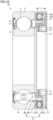
- Fig. 1 is a cross-sectional view of a bearing device according to a first embodiment in a plane including a rotation axis.
- a bearing with a wireless sensor is exemplified as a bearing device 1 illustrated in Fig. 1 .
- Bearing device 1 includes a bearing B, an external ring 7, a magnetic ring 8, and a stator 9.
- Bearing B includes an outer ring 2, an inner ring 3, rolling elements 4, a retainer 5, and a seal 6.
- External ring 7 is fixed to an inner diameter surface of outer ring 2.
- Magnetic ring 8 is fixed to an outer diameter surface of inner ring 3.
- Stator 9 is fixed to the inner diameter surface of external ring 7 so as to face magnetic ring 8.
- Magnetic ring 8 and stator 9 constitute a generator G.
- Generator G is a claw pole generator.
- Bearing B is, for example, a deep groove ball bearing in which rolling elements 4 are balls.
- inner ring rotation type in which inner ring 3 is a rotating wheel and outer ring 2 is a fixed wheel will be described as an example.
- Magnetic ring 8 includes a cored bar 8a and a multipolar magnet 8b.
- Multipolar magnet 8b is obtained by, for example, vulcanizing and bonding a magnetic material obtained by kneading magnetic powder and rubber to cored bar 8a, and then alternately magnetizing N poles and S poles, and is fixed to inner ring (rotating wheel) 3.
- Stator 9 includes two magnetic ring members 10-1 and 10-2 having the same shape, a bobbin 11, and a coil 12.
- the winding of coil 12 is wound a plurality of times in the circumferential direction of bobbin 11.
- a stator can be similarly configured even if a coil not using bobbin 11 is used.
- a resin case 13 is fixed to the inner diameter surface of external ring 7 so as to be adjacent to generator G.
- Circuit board 14 is fixed to case 13.
- Circuit board 14 is provided with a power circuit 15 that rectifies AC power generated by generator G and converts the AC power into DC power, a sensor 16 that monitors a state of bearing B, and a wireless communication circuit 17 that wirelessly transmits an output of sensor 16 to the outside.
- An end portion 12a that is a start of winding of coil 12 and an end portion 12b that is an end of winding of the coil are connected to circuit board 14.
- a lid 18 that protects circuit board 14 is made of a nonmagnetic insulator such as resin, and is fixed to external ring 7, for example.
- a surface of circuit board 14 may be sealed with a resin molding agent instead of lid 18.
- Circuit board 14 on which wireless communication circuit 17 is mounted is surrounded by a nonmagnetic insulator such as resin. Since a magnetic material or a conductor is not disposed on a side of lid 18 of circuit board 14, wireless communication is possible.
- case 13 is interposed between bearing B and circuit board 14.
- case 13 is made of a resin material having a low thermal conductivity, it is also possible to suppress rise of the temperature of circuit board 14.
- a material having excellent heat insulating properties such as resin containing fine bubbles, it is effective to suppress the temperature rise.
- seal 6 is not mounted on a side of bearing B to which magnetic ring 8 is fixed, making a gap between magnetic ring 8 and components such as stator 9 and case 13 narrowed provides a labyrinth seal (non-contact seal) structure, and thus it is possible to prevent foreign matters and the like from entering.
- a groove or the like may be provided on any of the opposing surfaces, or a contact type seal may be provided.
- FIG. 2 is a diagram illustrating a schematic configuration of generator G.
- Generator G is a claw pole type generator.
- a magnetic rotor includes a ring-shaped multipolar magnet 8b.
- stator 9 includes coil 12 and a magnetic yoke surrounding the coil.
- the magnetic yoke includes magnetic ring members 10-1 and 10-2.
- a magnetic flux emitted from the N pole of multipolar magnet 8b enters the magnetic yoke from a claw 10b which is a magnetic pole, goes around the coil, and enters the S pole of multipolar magnet 8b from claw 10b which is an adjacent magnetic pole.
- directions of the magnetic fluxes are reversed.
- the alternating magnetic fields generated in this manner generate an AC voltage at both ends of coil 12.
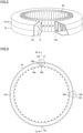
- Fig. 3 is a side view of a magnetic ring member 10.
- Fig. 4 is a cross-sectional view taken along line IV-IV of Fig. 3 . Referring to Figs. 3 and 4 , at one end of magnetic ring member 10, grooves 10a and claws 10b opened in an axial direction are alternately arranged in a comb shape.
- a recess 10c and a protrusion 10d are provided on an end surface 10f of magnetic ring member 10.
- positions of recess 10c and protrusion 10d are designed such that protrusion 10d of one magnetic ring member 10-2 is arranged with respect to recess 10c of the other magnetic ring member 10-1.
- a plurality of recesses and protrusions may be provided as illustrated in Fig. 3 .
- assembly is possible as long as protrusion 10d illustrated in a circle V1 and recess 10c illustrated in a circle V2 in Fig. 3 are provided.
- two recesses 10c and two protrusions 10d are provided in Fig. 3 in consideration of the balance at the time of assembly.
- a hole 10e provided in the side surface is provided in magnetic ring member 10 in order to pull out end portions 12a and 12b of coil 12 to the outside.
- Fig. 5 is a view illustrating a state in which two magnetic ring members 10 having the same shape are arranged to face each other.
- bobbin 11 wound with coil 12 is accommodated in a space between two magnetic ring members 10-1 and 10-2, but bobbin 11 wound with coil 12 is not illustrated here because the drawing becomes complicated.
- the number of magnetic poles of magnetic ring 8 including the N pole and the S pole is the same as that of claw 10b in the state of Fig. 6 .
- Fig. 6 is a view illustrating a state in which two magnetic ring members 10 are fitted.
- Fig. 7 is a cross-sectional view of a portion VII in Fig. 6 after fitting of the two magnetic ring members on a plane including the rotation axis of the bearing.
- bobbin 11 and coil 12 are arranged inside the stator as in Fig. 1 and the like, bobbin 11 and coil 12 are not illustrated in Fig. 7 .
- Two magnetic ring members 10-1, 10-2 of the same shape are used. Recess 10c and protrusion 10d provided on end surface 10f of each magnetic ring member 10 are fitted so that claws 10b provided on each magnetic ring member 10 are alternately arranged.
- end surface 10f of magnetic ring member 10 On end surface 10f of magnetic ring member 10, the same number of recesses 10c and protrusions 10d are provided.
- recesses 10c and protrusions 10d When recesses 10c and protrusions 10d are fitted and end surfaces 10f are brought into contact with each other, it is easy to align the phases of the arrangements so that a gap between claw 10b and claw 10b of respective magnetic ring members 10 become uniform.
- the plurality of recesses 10c and the plurality of protrusions 10d are arranged in the circumferential direction, the positions of magnetic ring members 10 can be fixed without being displaced from each other in the circumferential direction.
- End surfaces 10f of two magnetic ring members 10 come into contact with each other without a gap and provide a magnetic path.
- external ring 7 can be used as a magnetic path, and the magnetic resistance of the magnetic yoke can be suppressed to be small.
- two magnetic ring members 10 can be easily assembled without adhesion or welding.
- plastic working such as caulking (not illustrated) may be added to the fitting portion, or the fitting portion may be elastically deformed.
- magnetic ring member 10 is generally manufactured by press-forming a thin plate of a magnetic material with a die, but other than this method, the magnetic material may be deposited on the surface by plating, electrodeposition, or the like after injection molding of a resin material. In this manufacturing method, it is easy to manufacture even a fine claw shape that is difficult to plastically process by pressing.
- Fig. 8 is a diagram illustrating a configuration of circuit board 14.
- Circuit board 14 is provided with power circuit 15, sensor 16, and wireless communication circuit 17.
- Power circuit 15 smooths an alternating current obtained from generator G into a direct current, and boosts or steps down the alternating current at a subsequent stage to generate a DC power supply GV for driving sensor 16 and wireless communication circuit 17. Since a frequency of an AC signal obtained from generator G changes according to the rotation speed of inner ring 3, a rotation detection unit 20 can process the AC signal to obtain a rotation signal RP.
- Rotation detection unit 20 may be such a transistor.
- Sensor 16 is, for example, a temperature sensor or an acceleration sensor that monitors the state of bearing B.
- sensor 16 is mounted on circuit board 14, but the temperature sensor may be fixed in contact with or in the vicinity of outer ring 2 so as to directly measure the temperature of bearing B, and a sensor signal may be input to circuit board 14.
- Wireless communication circuit 17 includes an input unit 17a that inputs a sensor signal, an arithmetic unit 17b that performs arithmetic processing on the sensor signal, a transmission/reception unit 17c for transmitting and receiving data, and an antenna 17d.
- input unit 17a may include a DA converter. With such a configuration, by converting the sensor output into a digital signal in the immediate vicinity of sensor 16, it is possible to suppress mixing of electromagnetic noise.
- arithmetic unit 17b has functions of a central processing unit (CPU) and a memory, and performs arithmetic processing on information obtained from sensor 16.
- Wireless communication circuit 17 is, for example, a module compatible with a wireless standard such as Bluetooth (registered trademark) or Bluetooth Low Energy (registered trademark).
- wireless communication circuit 17 is preferably a circuit that can be driven with low power.
- wireless communication circuit 17 may be a communication circuit other than the wireless standards described above.
- circuit board 14 is fixed via case 13 made of a nonmagnetic material, a distance between antenna 17d and a magnetic material such as stator 9 can be increased, and therefore an influence on wireless communication is reduced.
- stator 9 from being arranged on a back side of wireless communication circuit 17, the influence on the wireless communication can be further reduced.
- the signal of sensor 16 may be processed into an index according to a purpose, such as a result of calculation of an average value by arithmetic unit 17b or a maximum value and a minimum value within a certain period of time, and then transmitted.
- a purpose such as a result of calculation of an average value by arithmetic unit 17b or a maximum value and a minimum value within a certain period of time.
- Fig. 9 is a diagram illustrating an improved example of circuit board 14 of Fig. 8 .
- generator G using the rotation of inner ring 3 When generator G using the rotation of inner ring 3 is used, necessary electric power cannot be secured unless inner ring 3 rotates at a certain speed or more. Therefore, in Fig. 9 , a battery 21 is mounted in addition to generator G. As such a configuration, when the power required by generator G cannot be secured, the power may be switched to the battery drive by a switch unit 19 and used. In addition, power generated by generator G may be stored in battery 21, and data may be intermittently transmitted after a sufficient amount of power is stored.
- Fig. 10 is a cross-sectional view of a bearing device 1A according to a first modification of the first embodiment in a plane including a rotation axis.
- Bearing device 1A is a bearing with a wireless sensor as an improved example of Fig. 1 .
- case 13 is disposed so as to be inserted into an inner diameter portion of magnetic ring 8, and circuit board 14 is disposed inside the case. Therefore, a width in the axial direction can be reduced as compared with the example of Fig. 1 , and magnetic ring 8 can be made compact.
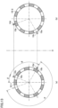
- Fig. 11 is a view for illustrating a condition for correspondingly fitting recess 10c and protrusion 10d provided for two magnetic ring members 10.
- recess 10c is indicated by a white circle
- protrusion 10d is indicated by a hatched circle.
- Fig. 11(a) is a view of magnetic ring member 10-1 viewed from the side of recess 10c and protrusion 10d, and shows an example in which one recess 10c and one protrusion 10d are provided.
- Recess 10c is provided at a position of ⁇ from the reference position
- protrusion 10d is provided at a position of ⁇ from recess 10c.
- Fig. 11(b) is a view illustrating arrangement of magnetic ring member 10-2.
- the arrangement of magnetic ring member 10-2 corresponds to the arrangement obtained by rotating Fig. 11(a) clockwise by an angle ⁇ so as to be line-symmetric with respect to a line O.
- recess 10c provided in magnetic ring member 10-1 and protrusion 10d provided in magnetic ring member 10-2 are fitted, and recess 10c provided in magnetic ring member 10-2 and protrusion 10d provided in magnetic ring member 10-1 are fitted.
- Fig. 12 is a view illustrating a phase of two magnetic ring members 10 in which groove 10a and claw 10b fit alternately.
- Fig. 12(a) illustrates arrangement of the groove and the claw of magnetic ring member 10-1.
- Fig. 12(b) illustrates arrangement of the groove and the claw of magnetic ring member 10-1.
- the state illustrated in Fig. 12(b) corresponds to a state of being rotated at angle ⁇ from the state of Fig. 12(a) .
- i represents an integer indicating the number of pitches to be shifted at the time of fitting
- n represents the number of grooves 10a and claws 10b of magnetic ring member 10
- 2 ⁇ /n represents a pitch P of the claws.
- outer ring 2 of bearing B is fixed to the stationary member
- inner ring 3 is fixed to the rotary member
- the rotary member is supported with respect to the stationary member.
- the present invention can be similarly applied to a case where the outer ring is rotational and the inner ring is stationary.
- Fig. 14 is a cross-sectional view of a bearing device 1B according to a second modification of the first embodiment in a plane including the rotation axis of bearing device 1B.
- Bearing device 1B is a modification of bearing device 1A illustrated in Fig. 10 , and is a bearing with a wireless sensor in which the outer ring is rotational.
- magnetic ring 8 is fixed to an inner diameter portion of outer ring 2, and multipolar magnet 8b is provided on a side of an inner diameter of cored bar 8a.
- a ring member 30 is fixed to an outer diameter surface of inner ring 3 serving as a fixed wheel.
- Stator 9 is fixed to a side of an outer diameter of ring member 30, and case 13 is fixed to a side of an inner diameter of the ring member.
- the claws aligned in a comb shape are arranged on the outer periphery of stator 9.
- Case 13 has a flange portion 30a protruding toward on the side of the outer diameter.
- a labyrinth structure in which a gap between flange portion 30a and magnetic ring 8 is narrowed is provided. The labyrinth structure prevents a foreign matter from entering.
- Circuit board 14 is fixed in the groove provided in case 13.
- Circuit board 14 is provided with power circuit 15 that rectifies AC power generated by generator G and converts the AC power into DC power, sensor 16 that monitors a state of bearing B, and wireless communication circuit 17 that wirelessly transmits an output of sensor 16 to the outside.
- End portion 12a that is the start of winding and end portion 12b that is the end of winding drawn from coil 12 are connected to circuit board 14.
- the AC power output from generator G when outer ring 2 rotates is converted into DC by power circuit 15.
- Lid 18 that protects circuit board 14 is made of a nonmagnetic insulator such as resin, and closes the opening of case 13.
- the surface of circuit board 14 may be sealed with a resin molding agent instead of lid 18.
- the first embodiment has described an example in which two magnetic ring members having an identical shape are combined to provide a magnetic ring.
- a second embodiment another example is shown in which two magnetic ring members having an identical shape are similarly combined to provide a magnetic ring. Portions other than the magnetic ring are similar to the configuration described in the first embodiment, and thus only the magnetic ring will be described below.
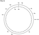
- Fig. 15 is a side view of a magnetic ring member 10A used in the second embodiment.
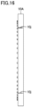
- Fig. 16 is a view of magnetic ring member 10A shown in Fig. 15 seen along an XVI arrow.
- grooves 10a and claws 10b opened in the axial direction are alternately arranged in a comb shape at one end of magnetic ring member 10A.
- a plurality of large-diameter portions 10g and small-diameter portions 10h having different outer diameters are provided at the other end.
- the number of large-diameter portions 10g is equal to the number of small-diameter portions 10h.
- a cutout portion 10j is provided at a boundary between large-diameter portion 10g and small-diameter portion 10h.
- Fig. 15 illustrates an example in which two large-diameter portions 10g and two small-diameter portions 10h are disposed.
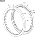
- Fig. 17 illustrates a state in which two magnetic ring members 10A having the same shape are arranged to face each other.
- Fig. 18 illustrates a state in which two magnetic ring members 10A are fitted.
- large-diameter portion 10g of magnetic ring member 10A-1 is fitted to small-diameter portion 10h of magnetic ring member 10A-2.
- Small-diameter portion 10h of magnetic ring member 10A-1 is fitted to large-diameter portion 10g of magnetic ring member 10A-2.
- Hole 10e provided in the side surface of magnetic ring member 10 is provided to pull out end portions 12a and 12b of coil 12 to the outside.
- bobbin 11 wound with coil 12 is accommodated in a space sandwiched between two magnetic ring members 10A-1 and 10A-2. However, since the drawing becomes complicated, bobbin 11 wound with coil 12 is not illustrated here.
- the number of magnetic poles of magnetic ring 8 including the N pole and the S pole is the same as that of claw 10b in the state of Fig. 18 .
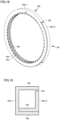
- Fig. 19 is a cross-sectional view of the XIX portion of the stator of Fig. 18 on a plane including the rotation axis.
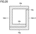
- Fig. 20 is a cross-sectional view of the XX portion of the stator in Fig. 18 on another plane including the rotation axis.
- bobbin 11 and coil 12 are arranged inside the stator as in Fig. 1 and the like, bobbin 11 and coil 12 are not illustrated in Figs. 19 and 20 .
- Claw 10b of magnetic ring member 10A-1 and claw 10b of magnetic ring member 10A-2 are disposed on one side (upper side in Figs. 19 and 20 ) with respect to coil 12, and in a cross section ( Fig. 20 ) in a certain plane, first member 10A-1 and second member 10A-2 overlap in the order of small-diameter portion 10h of first member 10A-1 and large-diameter portion 10g of second member 10A-2 in a direction away from the coil on a side (lower side in Fig. 20 ) opposite to the one side with respect to the coil.
- a cross section Fig.
- first member 10A-1 and second member 10A-2 overlap in the order of small-diameter portion 10h of second member 10A-2 and large-diameter portion 10g of first member 10A-1 in a direction away from the coil on the side (lower side in Fig. 19 ) opposite to the one side with respect to the coil.
- large-diameter portion 10g of magnetic ring member 10A-1 and small-diameter portion 10h of magnetic ring member 10A-2 are fitted to each other, and large-diameter portion 10g of magnetic ring member 10A-2 and small-diameter portion 10h of magnetic ring member 10A-1 are fitted to each other, such that claws 10b provided on magnetic ring member 10A-1 and claws 10b provided on magnetic ring member 10A-2 are alternately arranged.
- large-diameter portion 10g and small-diameter portion 10h abut on each other on the cylindrical surface, magnetic ring member 10A-1 and magnetic ring member 10A-2 can be restrained in position without being displaced in the circumferential direction, and the magnetic resistance can be reduced.
- large-diameter portion 10g and small-diameter portion 10h are provided, large-diameter portion 10g and small-diameter portion 10h are fitted by aligning the positions of cutout portions 10j, and gaps between claws 10b of magnetic ring member 10A-1 and claws 10b of magnetic ring member 10A-2 becomes uniform. Therefore, it is easy to perform phase matching between magnetic ring member 10A-1 and magnetic ring member 10A-2 at the time of assembly of stator 9.
- a stator structure of the claw pole power generation can be applied not only to the bearing but also to an outer-ring spacer.
- an example in which the stator structure of the claw pole generator is applied to an outer-ring spacer of a spindle device will be described.
- Fig. 21 is a cross-sectional view illustrating a schematic configuration in which the stator structure of the claw pole generator is applied to a bearing device of the spindle device.
- Fig. 22 is an enlarged view of a main part on the left side in Fig. 21 .
- Fig. 22 mainly illustrates a bearing device 90.
- a spindle device 50 illustrated in Fig. 21 is used as, for example, a built-in motor type spindle device of a machine tool.
- a motor 52 is incorporated on one end side of a spindle 51 supported by spindle device 50 for a machine tool spindle, and a cutting tool such as an end mill (not illustrated) is connected to the other end side.
- spindle device 50 includes bearings 53a and 53b, a spacer 54 disposed adjacent to bearings 53a and 53b, motor 52, and a bearing 55 disposed adjacent to motor 52 on a side opposite to spacer 54.
- Spindle 51 is rotatably supported by a plurality of bearings 53a and 53b provided in a housing 57 embedded in the inner diameter portion of an outer cylinder 56.
- Bearing 53a includes an inner ring 53ia, an outer ring 53ga, rolling elements Ta, and a retainer Rta.
- Bearing 53b includes an inner ring 53ib, an outer ring 53gb, rolling elements Tb, and a retainer Rtb.
- Spacer 54 includes an inner-ring spacer 54i and an outer-ring spacer 54g.
- rolling elements Ta and Tb are ceramic balls that are nonmetallic insulators, and retainers Rta and Rtb are made of resin.
- Inner ring 53ia of bearing 53a and inner ring 53ib of a bearing 5b separated in the axial direction are fitted to spindle 51 in an interference fit state (press fit state).
- Inner-ring spacer 54i is disposed between inner rings 53ia-53ib, and outer-ring spacer 54g is disposed between outer rings 53ga-53gb.
- Bearings 53a and 53b are bearings capable of applying a preload by an axial force, and an angular ball bearing, a deep groove ball bearing, a tapered roller bearing, or the like can be used.
- An angular ball bearing is used as bearing device 90 illustrated in Fig. 22 , and two bearings 53a and 53b are installed in back-to-back duplex (DB).
- Outer-ring spacer 54g is divided into two parts of a first outer-ring spacer 54g1 and a second outer-ring spacer 54g2 in the axial direction, and stator 9 of generator G is fixed therebetween.
- magnetic ring 8 is fixed to an outer peripheral surface of inner-ring spacer 54i, and stator 9 and multipolar magnet 8b of magnetic ring 8 are arranged to face each other with a gap therebetween, and thus generator G is configured.
- generator G the claw pole generator illustrated in Figs. 2 to 7 and 15 to 20 can be used.
- Magnetic ring 8 includes cored bar 8a and multipolar magnet 8b.
- Multipolar magnet 8b is obtained by, for example, vulcanizing and bonding a magnetic material obtained by kneading magnetic powder and rubber to cored bar 8a, and then alternately magnetizing N poles and S poles, and is fixed to inner-ring spacer 54i.
- Stator 9 includes two magnetic ring members 10-1 and 10-2 having the same shape, bobbin 11, and coil 12.
- the winding of coil 12 is wound a plurality of times in the circumferential direction of bobbin 11.
- bobbin 11 an example of using bobbin 11 is illustrated here, a stator can be similarly configured even if a coil not using bobbin 11 is used.
- a groove portion 54g1a is provided on an end surface of first outer-ring spacer 54g1, and circuit board 14 is mounted inside groove portion 54g1a.
- Circuit board 14 is provided with power circuit 15 that rectifies AC power generated by generator G and converts the AC power into DC power, sensor 16 that monitors the state of bearing device 90, and wireless communication circuit 17 that wirelessly transmits an output of sensor 16 to the outside.
- End portion 12a that is the start of winding of coil 12 and end portion 12b that is the end of winding of the coil are connected to circuit board 14 through a hole 54g1b.
- hole 54g1b is sealed using a sealing material after wiring to prevent oil or the like from entering a side of circuit board 14.
- Lid 18 that protects circuit board 14 is made of a nonmetallic insulator such as resin, and is fixed inside groove portion 54gla.
- the surface of circuit board 14 may be sealed with a resin molding agent instead of lid 18.
- a plurality of sensors such as a temperature sensor, an acceleration sensor, and a load sensor are mounted.
- the load sensor (not illustrated) is disposed between first outer-ring spacer 54g1 and second outer-ring spacer 54g2, signal processing is performed by circuit board 14, and an output thereof is wirelessly transmitted.
- Rolling bearing 55 of a single row is a cylindrical roller bearing.
- a radial load and an axial load acting on spindle device 50 are supported by bearings 53a and 53b as angular ball bearings.
- the load in the radial direction acting on spindle device 50 for a machine tool spindle is supported by single-row bearing 55 as a cylindrical roller bearing.
- a cooling medium flow path GV is provided in housing 57. By allowing a cooling medium to flow between housing 57 and outer cylinder 56, bearings 53a and 53b can be cooled.
- a lubricating oil supply passage is unnecessary, but when lubrication of air oil or the like is necessary, a lubricating oil supply passage is provided for outer-ring spacer 54g. Here, the lubricating oil supply passage is not illustrated.
- bearing 53a, spacer 54, bearing 53b, and a spacer 58 are inserted into spindle 51 in the stated order, and an initial preload is applied by tightening a nut 59.
- spindle 51 to which bearings 53a and 53b are attached is inserted into housing 57 until the right side of outer ring 53gb of bearing 53b in Fig. 22 is brought into contact with a stepped portion 57a provided in housing 57.
- a front lid 60 pushes outer ring 53ga of left bearing 53a to fix spindle 51 to housing 57.
- This force is transmitted to outer ring 53ga, rolling elements Ta, and inner ring 53ia in bearing 53a to apply a preload between raceway surfaces of inner ring 53ia and outer ring 53ga of a left bearing 5a and rolling elements Ta.
- the preload applied to bearings 53a and 53b is determined by, for example, a movement amount limited by a dimensional difference between a width of outer-ring spacer 54g and a width of inner-ring spacer 54i.
- an inner ring 55a is positioned in the axial direction by a cylindrical member 61 and an inner ring retainer 62 fitted to the outer periphery of spindle 51.
- Inner ring retainer 62 is prevented from coming off by a nut 63 screwed to spindle 51.
- An outer ring 55b of bearing 55 is sandwiched between a positioning member 65 and a positioning member 66 fixed to an end member 64.
- Inner ring 55a slides integrally with respect to end member 64 in accordance with expansion and contraction of spindle 51.
- Motor 52 that drives spindle 51 is disposed at an intermediate position in the axial direction between bearing 53b and single-row bearing 55 in a space 67 provided between spindle 51 and outer cylinder 56.
- a rotor 68 of motor 52 is fixed to cylindrical member 61 fitted to the outer periphery of spindle 51, and a stator 69 of motor 52 is fixed to the inner peripheral portion of outer cylinder 56.
- cooling medium flow path for cooling motor 52 is not illustrated.
- Outer-ring spacer 54g is provided with generator G, sensor 16, and wireless communication circuit 17 that wirelessly transmits the output of sensor 16 to the outside, and the operation status of spindle device 50 can be monitored and the sensor output can be wirelessly transmitted.
- an abnormality determination means (not illustrated) that determines the presence or absence of an abnormality from each sensor output may be mounted on circuit board 14, and an abnormality determination result may be wirelessly transmitted.
- the radio wave transmitted from wireless communication circuit 17 passes between outer ring 53ga and inner ring 53ia of bearing 53a, and is emitted from a gap 70 of the labyrinth seal provided by spindle 51 and front lid 60.
- spindle device 50 performs wireless communication, the wiring does not need to be drawn out from outer-ring spacer 54g. Therefore, it is not necessary to process a groove for wiring on the inner diameter side of housing 57, and the modification of spindle device 50 can be minimized.
- outer-ring spacer 54g and inner-ring spacer 54i are further provided.
- Magnetic ring 8 is fixed to inner-ring spacer 54i
- stator 9 is fixed to outer-ring spacer 54g so as to face magnetic ring 8.
- magnetic ring 8 may be fixed to outer-ring spacer 54g
- stator 9 may be fixed to inner-ring spacer 54i so as to face magnetic ring 8.
- circuit board 14 is fixed to inner-ring spacer 54i.
- bearing device 1 includes magnetic ring 8 fixed to a rotary member, and a stator 9 fixed to a non-rotary member so as to face magnetic ring 8.
- Magnetic ring 8 and stator 9 constitute claw pole type generator G.
- Stator 9 includes coil 12 and a magnetic yoke surrounding coil 12.
- the magnetic yoke is configured by combining first member 10-1 and second member 10-2 that are magnetic bodies.
- First member 10-1 includes a plurality of first claws 10b arranged in a comb shape
- second member 10-2 includes a plurality of second claws 10b arranged in a comb shape.
- the plurality of first claws 10b of first member 10-1 and the plurality of second claws 10b of second member 10-2 are alternately arranged on the surface facing magnetic ring 8.
- First member 10-1 and second member 10-2 have an identical shape.
- bearing device 1 further includes outer ring 2, inner ring 3 and a plurality of rolling elements 4 arranged between outer ring 2 and inner ring 3.
- Magnetic ring 8 is fixed to one of outer ring 2 and inner ring 3.
- Stator 9 is fixed to the other of outer ring 2 and inner ring 3 so as to face magnetic ring 8.
- bearing device 90 shown in Figs. 21 and 22 further includes outer-ring spacer 54g and inner-ring spacer 54i.
- Magnetic ring 8 is fixed to inner-ring spacer 54i
- stator 9 is fixed to outer-ring spacer 54g so as to face magnetic ring 8.
- magnetic ring 8 may be fixed to outer-ring spacer 54g
- stator 9 may be fixed to inner-ring spacer 54i so as to face magnetic ring 8.
- Stator 9 and magnetic ring 8 have an annular shape through which the rotation axis of bearing device 1 passes.
- first claws 10b and second claws 10b are arranged on one side with respect to coil 12, and end surface 10f of first member 10-1 and end surface 10f of second member 10-2 abut on the side opposite to the one side with respect to coil 12 in the cross section.
- a first recess 10c and a first protrusion 10d are provided on end surface 10f of first member 10-1, and a second recess 10c and a second protrusion 10d are provided on the end surface of the second member.
- first recess 10c abuts on second protrusion 10d
- first protrusion 10d abuts on second recess 10c.
- coil 12 illustrated in Fig. 2 and surrounded by first member 10-1 and second member 10-2 is not illustrated in Fig. 7 .
- ⁇ represents a rotation angle between first member 10-1 and second member 10-2
- ⁇ represents an angle indicating a position of first recess 10c from a reference position
- ⁇ represents an angle indicating a position of first protrusion 10d from the position of first recess 10c.
- ⁇ represents a rotation angle between first member 10-1 and second member 10-2.
- i represents an integer.
- n represents the number of the plurality of first claws 10b of first member 10-1 and the number of the plurality of second claws 10b of second member 10-2.
- 2 ⁇ /n represents each pitch P of the plurality of first claws 10b of first member 10-1 and the plurality of second claws 10b of second member 10-2.
- Stator 9 and magnetic ring 8 have an annular shape through which the rotation axis of bearing device 1 passes.
- one of first claw 10b of first member 10A-1 and second claw 10b of second member 10A-2 is disposed on one side (upper side in Figs. 19 and 20 ) with respect to coil 12.
- first member 10A-1 and second member 10A-2 overlap in the order of first member 10A-1 and second member 10A-2 in the direction away from the coil on a side opposite to the one side (lower side in Fig. 20 ) with respect to the coil.
- first member 10A-1 and second member 10A-2 overlap in the order of second member 10A-2 and first member 10A-1 in the direction away from the coil on a side opposite to the one side with respect to the coil.
- first member 10A-1 and second member 10A-2 overlap each other at the portion opposite to claw 10b, the contact area can be increased to reduce the magnetic resistance of the magnetic yoke.
- the manufacturing method for manufacturing the bearing device or the spacer includes: punching first member 10-1 and second member 10-2 by press working, using a die having an identical shape; and assembling first member 10-1, second member 10-2, and coil 12 to constitute stator 9.
- 1, 1A, 1B, 90 bearing device, 2, 53ga, 53gb, 55b: outer ring, 3, 53ia, 53ib, 55a: inner ring, 4, Ta, Tb: rolling element, 5, Rta, Rtb: retainer, 5a, 5b, 53a, 53b, 55, B: bearing, 6: seal, 7: external ring, 8: magnetic ring, 8a: cored bar, 8b: multipolar magnet, 9, 69: stator, 10, 10-1, 10-2, 10A, 10A-1, 10A-2: magnetic ring member, 10a: groove, 10b: claw, 10c: recess, 10d: protrusion, 10e: hole, 10f: end surface, 10g: large-diameter portion, 10h: small-diameter portion, 10j: cutout portion, 11: bobbin, 12: coil, 12a, 12b: end portion, 13: case, 14: circuit board, 15: power circuit, 16: sensor, 17: wireless communication circuit, 17a: input unit,
Landscapes
- Engineering & Computer Science (AREA)
- General Engineering & Computer Science (AREA)
- Mechanical Engineering (AREA)
- Power Engineering (AREA)
- Microelectronics & Electronic Packaging (AREA)
- Physics & Mathematics (AREA)
- General Physics & Mathematics (AREA)
- Rolling Contact Bearings (AREA)
Claims (4)
- Lagervorrichtung (1, 1A, 1B, 90), die ein Rotationselement drehbar stützt, wobei die Lagervorrichtung (1, 1A, 1B, 90) umfasst:einen Magnetring (8), der an dem Rotationselement befestigt ist; undeinen Stator (9), der an einem Nicht-Rotationselement so befestigt ist, dass er dem Magnetring (8) zugewandt ist, wobei:der Magnetring (8) und der Stator (9) einen Generator (G) vom Klauenpoltyp bilden,wobei der Stator (9) aufweist:eine Spule (12) undein magnetisches Joch, das die Spule (12) umgibt,das magnetische Joch durch Kombinieren eines ersten Elements (10A-1) und eines zweiten Elements (10A-2), die magnetische Körper sind, eingerichtet ist,das erste Element (10A-1) mehrere erste Klauen (10b) aufweist, die in einer Kammform angeordnet sind,das zweite Element (10A-2) mehrere zweite Klauen (10b) aufweist, die in einer Kammform angeordnet sind,die mehreren ersten Klauen (10b) und die mehreren zweiten Klauen (10b) abwechselnd auf einer Fläche angeordnet sind, die dem Magnetring (8) zugewandt ist, unddas erste Element (10A-1) und das zweite Element (10A-2) eine identische Form aufweisen, wobei der Stator (9) und der Magnetring (8) eine Ringform aufweisen, durch die eine Rotationsachse der Lagervorrichtung (1, 1A, 1B, 90) verläuft,eine der mehreren ersten Klauen (10b) und der mehreren zweiten Klauen (10b) auf einer Seite in Bezug auf die Spule (12) in Querschnitten des Stators (9) in einer ersten Ebene und einer zweiten Ebene, die die Rotationsachse aufweisen, angeordnet sind,dadurch gekennzeichnet, dassdas erste Element (10A-1) und das zweite Element (10A-2) einander in der Reihenfolge des ersten Elements (10A-1) und des zweiten Elements (10A-2) in einer Richtung von der Spule (12) fort auf einer Seite überlappen, die der einen Seite in Bezug auf die Spule (12) im Querschnitt in der ersten Ebene gegenüberliegt, unddas erste Element (10A-1) und das zweite Element (10A-2) einander in der Reihenfolge des zweiten Elements (10A-2) und des ersten Elements (10A-1) in einer Richtung von der Spule (12) fort auf einer Seite überlappen, die der einen Seite in Bezug auf die Spule (12) im Querschnitt in der zweiten Ebene gegenüberliegt.
- Lagervorrichtung (1, 1A, 1B) nach Anspruch 1, des Weiteren umfassend:einen Außenring (2);einen Innenring (3), undmehrere Wälzkörper (4), die zwischen dem Außenring (2) und dem Innenring (3) angeordnet sind, wobeider Magnetring (8) an einem des Außenrings (2) und des Innenrings (3) befestigt ist und der Stator (9) an dem anderen des Außenrings (2) und des Innenrings (3) so befestigt ist, dass er dem Magnetring (8) zugewandt ist.
- Lagervorrichtung (90) nach Anspruch 1, des Weiteren umfassend:einen Außenring-Abstandshalter (54g); undeinen Innenring-Abstandshalter (54i), wobeider Magnetring (8) an einem des Außenring-Abstandshalter (54g) und des Innenring-Abstandshalter (54i) befestigt ist undder Stator (9) an dem anderen des Außenring-Abstandshalter (54g) und des Innenring-Abstandshalter (54i) so befestigt, dass er dem Magnetring (8) zugewandt ist.
- Herstellungsverfahren zur Herstellung der Lagervorrichtung (1, 1A, 1B, 90) nach einem der Ansprüche 1 bis 3, wobei das Herstellungsverfahren umfasst:Stanzen des ersten Elements (10A-1) und des zweiten Elements (10A-2) durch Pressen unter Verwendung eines Stempels, der eine identische Form aufweist; undZusammenbauen des ersten Elements (10A-1), des zweiten Elements (10A-2) und der Spule (12), um den Stator (9) zu bilden.
Applications Claiming Priority (3)
| Application Number | Priority Date | Filing Date | Title |
|---|---|---|---|
| JP2020023669 | 2020-02-14 | ||
| JP2021003421A JP7731204B2 (ja) | 2020-02-14 | 2021-01-13 | 軸受装置、間座および製造方法 |
| PCT/JP2021/003613 WO2021161843A1 (ja) | 2020-02-14 | 2021-02-02 | 軸受装置、間座および製造方法 |
Publications (3)
| Publication Number | Publication Date |
|---|---|
| EP4106149A1 EP4106149A1 (de) | 2022-12-21 |
| EP4106149A4 EP4106149A4 (de) | 2023-11-22 |
| EP4106149B1 true EP4106149B1 (de) | 2024-08-14 |
Family
ID=77291803
Family Applications (1)
| Application Number | Title | Priority Date | Filing Date |
|---|---|---|---|
| EP21753193.8A Active EP4106149B1 (de) | 2020-02-14 | 2021-02-02 | Lagervorrichtung, und herstellungsverfahren |
Country Status (4)
| Country | Link |
|---|---|
| US (1) | US12066056B2 (de) |
| EP (1) | EP4106149B1 (de) |
| CN (1) | CN115088159A (de) |
| WO (1) | WO2021161843A1 (de) |
Families Citing this family (7)
| Publication number | Priority date | Publication date | Assignee | Title |
|---|---|---|---|---|
| EP4484778B1 (de) * | 2022-03-24 | 2026-05-06 | NTN Corporation | Lagervorrichtung |
| JP7450657B2 (ja) * | 2022-03-24 | 2024-03-15 | Ntn株式会社 | 軸受装置 |
| JP7765327B2 (ja) * | 2022-03-24 | 2025-11-06 | Ntn株式会社 | 軸受装置 |
| JP7808995B2 (ja) * | 2022-03-30 | 2026-01-30 | Ntn株式会社 | 軸受装置 |
| JP7797278B2 (ja) * | 2022-03-30 | 2026-01-13 | Ntn株式会社 | センサ付き軸受及び軸受装置 |
| JP2024036860A (ja) * | 2022-09-06 | 2024-03-18 | Ntn株式会社 | 軸受装置 |
| CN117145875A (zh) * | 2023-04-21 | 2023-12-01 | 浙江师范大学 | 一种自发电监测的滑动轴承 |
Family Cites Families (9)
| Publication number | Priority date | Publication date | Assignee | Title |
|---|---|---|---|---|
| JPH037672U (de) * | 1989-06-13 | 1991-01-24 | ||
| EP1342633B1 (de) | 2002-03-08 | 2010-01-13 | Ntn Corporation | Dreherkennungsvorrichtung und Antiblockierbremssystem mit einer solchen Vorrichtung |
| JP2006170624A (ja) | 2004-12-10 | 2006-06-29 | Ntn Corp | ワイヤレスセンサ付き軸受 |
| JP2008072854A (ja) * | 2006-09-15 | 2008-03-27 | Hitachi Industrial Equipment Systems Co Ltd | 多相クローポール型モータ |
| JP5039348B2 (ja) * | 2006-09-20 | 2012-10-03 | 株式会社日立産機システム | モータ、及びそれを用いたファン装置 |
| JP2009207257A (ja) * | 2008-02-27 | 2009-09-10 | Honda Motor Co Ltd | クローポール型モータのステータ |
| JP6915478B2 (ja) * | 2017-09-27 | 2021-08-04 | 株式会社ジェイテクト | 転がり軸受装置 |
| JP7362239B2 (ja) | 2018-02-13 | 2023-10-17 | Ntn株式会社 | 軸受装置およびスピンドル装置 |
| JP7155583B2 (ja) * | 2018-03-30 | 2022-10-19 | 日本精工株式会社 | センサ付き発電ユニットおよびセンサ付き軸受 |
-
2021
- 2021-02-02 US US17/798,830 patent/US12066056B2/en active Active
- 2021-02-02 EP EP21753193.8A patent/EP4106149B1/de active Active
- 2021-02-02 WO PCT/JP2021/003613 patent/WO2021161843A1/ja not_active Ceased
- 2021-02-02 CN CN202180014453.8A patent/CN115088159A/zh active Pending
Also Published As
| Publication number | Publication date |
|---|---|
| US12066056B2 (en) | 2024-08-20 |
| EP4106149A4 (de) | 2023-11-22 |
| WO2021161843A1 (ja) | 2021-08-19 |
| US20230086645A1 (en) | 2023-03-23 |
| EP4106149A1 (de) | 2022-12-21 |
| CN115088159A (zh) | 2022-09-20 |
Similar Documents
| Publication | Publication Date | Title |
|---|---|---|
| EP4106149B1 (de) | Lagervorrichtung, und herstellungsverfahren | |
| JP7731204B2 (ja) | 軸受装置、間座および製造方法 | |
| US10240637B2 (en) | Bearing structure | |
| US10837494B2 (en) | Bearing assembly with integrated generator | |
| EP3157141A1 (de) | Motor | |
| WO2023189588A1 (ja) | 軸受装置および発電機 | |
| JP7808995B2 (ja) | 軸受装置 | |
| US9118222B2 (en) | Outer rotor-type brushless motor | |
| JP2024161229A (ja) | 軸受装置 | |
| CN218569951U (zh) | 转子、旋转电机以及泵 | |
| EP4317718A1 (de) | Integrierte resolverlagervorrichtung und verfahren zur herstellung davon | |
| JP6891445B2 (ja) | ワイヤレスセンサ付き軸受 | |
| WO2023167247A1 (ja) | 軸受装置 | |
| JP7450657B2 (ja) | 軸受装置 | |
| JP7765327B2 (ja) | 軸受装置 | |
| WO2023182091A1 (ja) | 軸受装置 | |
| JP7633341B1 (ja) | 軸受装置の製造方法および軸受装置 | |
| CN119836529A (zh) | 轴承装置 | |
| JP7814216B2 (ja) | 軸受装置 | |
| JP7796573B2 (ja) | 軸受装置 | |
| WO2025205206A1 (ja) | データ集積装置およびデータ集積システム | |
| JP2025147610A (ja) | 軸受装置および異常検知システム | |
| JP2025150655A (ja) | 軸受装置 | |
| JP2025049810A (ja) | 軸受装置 | |
| JP2022157815A (ja) | レゾルバ一体型軸受装置 |
Legal Events
| Date | Code | Title | Description |
|---|---|---|---|
| STAA | Information on the status of an ep patent application or granted ep patent |
Free format text: STATUS: THE INTERNATIONAL PUBLICATION HAS BEEN MADE |
|
| PUAI | Public reference made under article 153(3) epc to a published international application that has entered the european phase |
Free format text: ORIGINAL CODE: 0009012 |
|
| STAA | Information on the status of an ep patent application or granted ep patent |
Free format text: STATUS: REQUEST FOR EXAMINATION WAS MADE |
|
| 17P | Request for examination filed |
Effective date: 20220824 |
|
| AK | Designated contracting states |
Kind code of ref document: A1 Designated state(s): AL AT BE BG CH CY CZ DE DK EE ES FI FR GB GR HR HU IE IS IT LI LT LU LV MC MK MT NL NO PL PT RO RS SE SI SK SM TR |
|
| DAV | Request for validation of the european patent (deleted) | ||
| DAX | Request for extension of the european patent (deleted) | ||
| A4 | Supplementary search report drawn up and despatched |
Effective date: 20231019 |
|
| RIC1 | Information provided on ipc code assigned before grant |
Ipc: G01P 3/44 20060101ALI20231013BHEP Ipc: H02K 21/14 20060101ALI20231013BHEP Ipc: H02K 11/35 20160101ALI20231013BHEP Ipc: H02K 11/25 20160101ALI20231013BHEP Ipc: H02K 11/21 20160101ALI20231013BHEP Ipc: H02K 7/18 20060101ALI20231013BHEP Ipc: H02K 7/08 20060101ALI20231013BHEP Ipc: G01P 3/487 20060101ALI20231013BHEP Ipc: F16C 41/00 20060101ALI20231013BHEP Ipc: F16C 33/80 20060101ALI20231013BHEP Ipc: F16C 19/06 20060101ALI20231013BHEP Ipc: H02K 1/14 20060101AFI20231013BHEP |
|
| GRAP | Despatch of communication of intention to grant a patent |
Free format text: ORIGINAL CODE: EPIDOSNIGR1 |
|
| STAA | Information on the status of an ep patent application or granted ep patent |
Free format text: STATUS: GRANT OF PATENT IS INTENDED |
|
| INTG | Intention to grant announced |
Effective date: 20240508 |
|
| GRAS | Grant fee paid |
Free format text: ORIGINAL CODE: EPIDOSNIGR3 |
|
| GRAA | (expected) grant |
Free format text: ORIGINAL CODE: 0009210 |
|
| STAA | Information on the status of an ep patent application or granted ep patent |
Free format text: STATUS: THE PATENT HAS BEEN GRANTED |
|
| AK | Designated contracting states |
Kind code of ref document: B1 Designated state(s): AL AT BE BG CH CY CZ DE DK EE ES FI FR GB GR HR HU IE IS IT LI LT LU LV MC MK MT NL NO PL PT RO RS SE SI SK SM TR |
|
| REG | Reference to a national code |
Ref country code: GB Ref legal event code: FG4D |
|
| REG | Reference to a national code |
Ref country code: CH Ref legal event code: EP |
|
| REG | Reference to a national code |
Ref country code: DE Ref legal event code: R096 Ref document number: 602021017267 Country of ref document: DE |
|
| REG | Reference to a national code |
Ref country code: IE Ref legal event code: FG4D |
|
| REG | Reference to a national code |
Ref country code: LT Ref legal event code: MG9D |
|
| REG | Reference to a national code |
Ref country code: NL Ref legal event code: MP Effective date: 20240814 |
|
| PG25 | Lapsed in a contracting state [announced via postgrant information from national office to epo] |
Ref country code: NO Free format text: LAPSE BECAUSE OF FAILURE TO SUBMIT A TRANSLATION OF THE DESCRIPTION OR TO PAY THE FEE WITHIN THE PRESCRIBED TIME-LIMIT Effective date: 20241114 |
|
| REG | Reference to a national code |
Ref country code: AT Ref legal event code: MK05 Ref document number: 1714188 Country of ref document: AT Kind code of ref document: T Effective date: 20240814 |
|
| PG25 | Lapsed in a contracting state [announced via postgrant information from national office to epo] |
Ref country code: PT Free format text: LAPSE BECAUSE OF FAILURE TO SUBMIT A TRANSLATION OF THE DESCRIPTION OR TO PAY THE FEE WITHIN THE PRESCRIBED TIME-LIMIT Effective date: 20241216 Ref country code: FI Free format text: LAPSE BECAUSE OF FAILURE TO SUBMIT A TRANSLATION OF THE DESCRIPTION OR TO PAY THE FEE WITHIN THE PRESCRIBED TIME-LIMIT Effective date: 20240814 Ref country code: NL Free format text: LAPSE BECAUSE OF FAILURE TO SUBMIT A TRANSLATION OF THE DESCRIPTION OR TO PAY THE FEE WITHIN THE PRESCRIBED TIME-LIMIT Effective date: 20240814 Ref country code: PL Free format text: LAPSE BECAUSE OF FAILURE TO SUBMIT A TRANSLATION OF THE DESCRIPTION OR TO PAY THE FEE WITHIN THE PRESCRIBED TIME-LIMIT Effective date: 20240814 Ref country code: GR Free format text: LAPSE BECAUSE OF FAILURE TO SUBMIT A TRANSLATION OF THE DESCRIPTION OR TO PAY THE FEE WITHIN THE PRESCRIBED TIME-LIMIT Effective date: 20241115 |
|
| PG25 | Lapsed in a contracting state [announced via postgrant information from national office to epo] |
Ref country code: BG Free format text: LAPSE BECAUSE OF FAILURE TO SUBMIT A TRANSLATION OF THE DESCRIPTION OR TO PAY THE FEE WITHIN THE PRESCRIBED TIME-LIMIT Effective date: 20240814 |
|
| PG25 | Lapsed in a contracting state [announced via postgrant information from national office to epo] |
Ref country code: LV Free format text: LAPSE BECAUSE OF FAILURE TO SUBMIT A TRANSLATION OF THE DESCRIPTION OR TO PAY THE FEE WITHIN THE PRESCRIBED TIME-LIMIT Effective date: 20240814 |
|
| PG25 | Lapsed in a contracting state [announced via postgrant information from national office to epo] |
Ref country code: AT Free format text: LAPSE BECAUSE OF FAILURE TO SUBMIT A TRANSLATION OF THE DESCRIPTION OR TO PAY THE FEE WITHIN THE PRESCRIBED TIME-LIMIT Effective date: 20240814 Ref country code: IS Free format text: LAPSE BECAUSE OF FAILURE TO SUBMIT A TRANSLATION OF THE DESCRIPTION OR TO PAY THE FEE WITHIN THE PRESCRIBED TIME-LIMIT Effective date: 20241214 |
|
| PG25 | Lapsed in a contracting state [announced via postgrant information from national office to epo] |
Ref country code: HR Free format text: LAPSE BECAUSE OF FAILURE TO SUBMIT A TRANSLATION OF THE DESCRIPTION OR TO PAY THE FEE WITHIN THE PRESCRIBED TIME-LIMIT Effective date: 20240814 |
|
| PG25 | Lapsed in a contracting state [announced via postgrant information from national office to epo] |
Ref country code: RS Free format text: LAPSE BECAUSE OF FAILURE TO SUBMIT A TRANSLATION OF THE DESCRIPTION OR TO PAY THE FEE WITHIN THE PRESCRIBED TIME-LIMIT Effective date: 20241114 Ref country code: ES Free format text: LAPSE BECAUSE OF FAILURE TO SUBMIT A TRANSLATION OF THE DESCRIPTION OR TO PAY THE FEE WITHIN THE PRESCRIBED TIME-LIMIT Effective date: 20240814 |
|
| PG25 | Lapsed in a contracting state [announced via postgrant information from national office to epo] |
Ref country code: RS Free format text: LAPSE BECAUSE OF FAILURE TO SUBMIT A TRANSLATION OF THE DESCRIPTION OR TO PAY THE FEE WITHIN THE PRESCRIBED TIME-LIMIT Effective date: 20241114 Ref country code: PT Free format text: LAPSE BECAUSE OF FAILURE TO SUBMIT A TRANSLATION OF THE DESCRIPTION OR TO PAY THE FEE WITHIN THE PRESCRIBED TIME-LIMIT Effective date: 20241216 Ref country code: PL Free format text: LAPSE BECAUSE OF FAILURE TO SUBMIT A TRANSLATION OF THE DESCRIPTION OR TO PAY THE FEE WITHIN THE PRESCRIBED TIME-LIMIT Effective date: 20240814 Ref country code: NO Free format text: LAPSE BECAUSE OF FAILURE TO SUBMIT A TRANSLATION OF THE DESCRIPTION OR TO PAY THE FEE WITHIN THE PRESCRIBED TIME-LIMIT Effective date: 20241114 Ref country code: NL Free format text: LAPSE BECAUSE OF FAILURE TO SUBMIT A TRANSLATION OF THE DESCRIPTION OR TO PAY THE FEE WITHIN THE PRESCRIBED TIME-LIMIT Effective date: 20240814 Ref country code: LV Free format text: LAPSE BECAUSE OF FAILURE TO SUBMIT A TRANSLATION OF THE DESCRIPTION OR TO PAY THE FEE WITHIN THE PRESCRIBED TIME-LIMIT Effective date: 20240814 Ref country code: IS Free format text: LAPSE BECAUSE OF FAILURE TO SUBMIT A TRANSLATION OF THE DESCRIPTION OR TO PAY THE FEE WITHIN THE PRESCRIBED TIME-LIMIT Effective date: 20241214 Ref country code: HR Free format text: LAPSE BECAUSE OF FAILURE TO SUBMIT A TRANSLATION OF THE DESCRIPTION OR TO PAY THE FEE WITHIN THE PRESCRIBED TIME-LIMIT Effective date: 20240814 Ref country code: GR Free format text: LAPSE BECAUSE OF FAILURE TO SUBMIT A TRANSLATION OF THE DESCRIPTION OR TO PAY THE FEE WITHIN THE PRESCRIBED TIME-LIMIT Effective date: 20241115 Ref country code: FI Free format text: LAPSE BECAUSE OF FAILURE TO SUBMIT A TRANSLATION OF THE DESCRIPTION OR TO PAY THE FEE WITHIN THE PRESCRIBED TIME-LIMIT Effective date: 20240814 Ref country code: ES Free format text: LAPSE BECAUSE OF FAILURE TO SUBMIT A TRANSLATION OF THE DESCRIPTION OR TO PAY THE FEE WITHIN THE PRESCRIBED TIME-LIMIT Effective date: 20240814 Ref country code: BG Free format text: LAPSE BECAUSE OF FAILURE TO SUBMIT A TRANSLATION OF THE DESCRIPTION OR TO PAY THE FEE WITHIN THE PRESCRIBED TIME-LIMIT Effective date: 20240814 Ref country code: AT Free format text: LAPSE BECAUSE OF FAILURE TO SUBMIT A TRANSLATION OF THE DESCRIPTION OR TO PAY THE FEE WITHIN THE PRESCRIBED TIME-LIMIT Effective date: 20240814 |
|
| PG25 | Lapsed in a contracting state [announced via postgrant information from national office to epo] |
Ref country code: SM Free format text: LAPSE BECAUSE OF FAILURE TO SUBMIT A TRANSLATION OF THE DESCRIPTION OR TO PAY THE FEE WITHIN THE PRESCRIBED TIME-LIMIT Effective date: 20240814 Ref country code: RO Free format text: LAPSE BECAUSE OF FAILURE TO SUBMIT A TRANSLATION OF THE DESCRIPTION OR TO PAY THE FEE WITHIN THE PRESCRIBED TIME-LIMIT Effective date: 20240814 Ref country code: DK Free format text: LAPSE BECAUSE OF FAILURE TO SUBMIT A TRANSLATION OF THE DESCRIPTION OR TO PAY THE FEE WITHIN THE PRESCRIBED TIME-LIMIT Effective date: 20240814 |
|
| PG25 | Lapsed in a contracting state [announced via postgrant information from national office to epo] |
Ref country code: EE Free format text: LAPSE BECAUSE OF FAILURE TO SUBMIT A TRANSLATION OF THE DESCRIPTION OR TO PAY THE FEE WITHIN THE PRESCRIBED TIME-LIMIT Effective date: 20240814 |
|
| PG25 | Lapsed in a contracting state [announced via postgrant information from national office to epo] |
Ref country code: CZ Free format text: LAPSE BECAUSE OF FAILURE TO SUBMIT A TRANSLATION OF THE DESCRIPTION OR TO PAY THE FEE WITHIN THE PRESCRIBED TIME-LIMIT Effective date: 20240814 |
|
| PG25 | Lapsed in a contracting state [announced via postgrant information from national office to epo] |
Ref country code: SK Free format text: LAPSE BECAUSE OF FAILURE TO SUBMIT A TRANSLATION OF THE DESCRIPTION OR TO PAY THE FEE WITHIN THE PRESCRIBED TIME-LIMIT Effective date: 20240814 Ref country code: IT Free format text: LAPSE BECAUSE OF FAILURE TO SUBMIT A TRANSLATION OF THE DESCRIPTION OR TO PAY THE FEE WITHIN THE PRESCRIBED TIME-LIMIT Effective date: 20240814 |
|
| REG | Reference to a national code |
Ref country code: DE Ref legal event code: R097 Ref document number: 602021017267 Country of ref document: DE |
|
| PLBE | No opposition filed within time limit |
Free format text: ORIGINAL CODE: 0009261 |
|
| STAA | Information on the status of an ep patent application or granted ep patent |
Free format text: STATUS: NO OPPOSITION FILED WITHIN TIME LIMIT |
|
| 26N | No opposition filed |
Effective date: 20250515 |
|
| PG25 | Lapsed in a contracting state [announced via postgrant information from national office to epo] |
Ref country code: SE Free format text: LAPSE BECAUSE OF FAILURE TO SUBMIT A TRANSLATION OF THE DESCRIPTION OR TO PAY THE FEE WITHIN THE PRESCRIBED TIME-LIMIT Effective date: 20240814 |
|
| PG25 | Lapsed in a contracting state [announced via postgrant information from national office to epo] |
Ref country code: MC Free format text: LAPSE BECAUSE OF FAILURE TO SUBMIT A TRANSLATION OF THE DESCRIPTION OR TO PAY THE FEE WITHIN THE PRESCRIBED TIME-LIMIT Effective date: 20240814 |
|
| REG | Reference to a national code |
Ref country code: CH Ref legal event code: PL |
|
| PG25 | Lapsed in a contracting state [announced via postgrant information from national office to epo] |
Ref country code: LU Free format text: LAPSE BECAUSE OF NON-PAYMENT OF DUE FEES Effective date: 20250202 |
|
| PG25 | Lapsed in a contracting state [announced via postgrant information from national office to epo] |
Ref country code: CH Free format text: LAPSE BECAUSE OF NON-PAYMENT OF DUE FEES Effective date: 20250228 |
|
| GBPC | Gb: european patent ceased through non-payment of renewal fee |
Effective date: 20250202 |
|
| REG | Reference to a national code |
Ref country code: BE Ref legal event code: MM Effective date: 20250228 |
|
| PG25 | Lapsed in a contracting state [announced via postgrant information from national office to epo] |
Ref country code: GB Free format text: LAPSE BECAUSE OF NON-PAYMENT OF DUE FEES Effective date: 20250202 |
|
| PGFP | Annual fee paid to national office [announced via postgrant information from national office to epo] |
Ref country code: FR Payment date: 20251231 Year of fee payment: 6 |
|
| PG25 | Lapsed in a contracting state [announced via postgrant information from national office to epo] |
Ref country code: BE Free format text: LAPSE BECAUSE OF NON-PAYMENT OF DUE FEES Effective date: 20250228 |
|
| PG25 | Lapsed in a contracting state [announced via postgrant information from national office to epo] |
Ref country code: IE Free format text: LAPSE BECAUSE OF NON-PAYMENT OF DUE FEES Effective date: 20250202 |
|
| PGFP | Annual fee paid to national office [announced via postgrant information from national office to epo] |
Ref country code: DE Payment date: 20251230 Year of fee payment: 6 |