EP4106558B1 - Article de génération d'aérosol ayant un élément de pontage comportant un facteur de réflectance - Google Patents
Article de génération d'aérosol ayant un élément de pontage comportant un facteur de réflectance Download PDFInfo
- Publication number
- EP4106558B1 EP4106558B1 EP21705229.9A EP21705229A EP4106558B1 EP 4106558 B1 EP4106558 B1 EP 4106558B1 EP 21705229 A EP21705229 A EP 21705229A EP 4106558 B1 EP4106558 B1 EP 4106558B1
- Authority
- EP
- European Patent Office
- Prior art keywords
- aerosol
- bridging element
- wrapper
- filter
- cavity
- Prior art date
- Legal status (The legal status is an assumption and is not a legal conclusion. Google has not performed a legal analysis and makes no representation as to the accuracy of the status listed.)
- Active
Links
Images
Classifications
-
- A—HUMAN NECESSITIES
- A24—TOBACCO; CIGARS; CIGARETTES; SIMULATED SMOKING DEVICES; SMOKERS' REQUISITES
- A24D—CIGARS; CIGARETTES; TOBACCO SMOKE FILTERS; MOUTHPIECES OF CIGARS OR CIGARETTES; MANUFACTURE OF TOBACCO SMOKE FILTERS OR MOUTHPIECES
- A24D1/00—Cigars; Cigarettes
- A24D1/02—Cigars; Cigarettes with special covers
- A24D1/025—Cigars; Cigarettes with special covers the covers having material applied to defined areas, e.g. bands for reducing the ignition propensity
-
- A—HUMAN NECESSITIES
- A24—TOBACCO; CIGARS; CIGARETTES; SIMULATED SMOKING DEVICES; SMOKERS' REQUISITES
- A24D—CIGARS; CIGARETTES; TOBACCO SMOKE FILTERS; MOUTHPIECES OF CIGARS OR CIGARETTES; MANUFACTURE OF TOBACCO SMOKE FILTERS OR MOUTHPIECES
- A24D1/00—Cigars; Cigarettes
- A24D1/20—Cigarettes specially adapted for simulated smoking devices
-
- A—HUMAN NECESSITIES
- A24—TOBACCO; CIGARS; CIGARETTES; SIMULATED SMOKING DEVICES; SMOKERS' REQUISITES
- A24D—CIGARS; CIGARETTES; TOBACCO SMOKE FILTERS; MOUTHPIECES OF CIGARS OR CIGARETTES; MANUFACTURE OF TOBACCO SMOKE FILTERS OR MOUTHPIECES
- A24D1/00—Cigars; Cigarettes
- A24D1/02—Cigars; Cigarettes with special covers
-
- A—HUMAN NECESSITIES
- A24—TOBACCO; CIGARS; CIGARETTES; SIMULATED SMOKING DEVICES; SMOKERS' REQUISITES
- A24C—MACHINES FOR MAKING CIGARS OR CIGARETTES
- A24C5/00—Making cigarettes; Making tipping materials for, or attaching filters or mouthpieces to, cigars or cigarettes
- A24C5/01—Making cigarettes for simulated smoking devices
-
- A—HUMAN NECESSITIES
- A24—TOBACCO; CIGARS; CIGARETTES; SIMULATED SMOKING DEVICES; SMOKERS' REQUISITES
- A24C—MACHINES FOR MAKING CIGARS OR CIGARETTES
- A24C5/00—Making cigarettes; Making tipping materials for, or attaching filters or mouthpieces to, cigars or cigarettes
- A24C5/47—Attaching filters or mouthpieces to cigars or cigarettes, e.g. inserting filters into cigarettes or their mouthpieces
- A24C5/471—Attaching filters or mouthpieces to cigars or cigarettes, e.g. inserting filters into cigarettes or their mouthpieces by means of a connecting band
-
- A—HUMAN NECESSITIES
- A24—TOBACCO; CIGARS; CIGARETTES; SIMULATED SMOKING DEVICES; SMOKERS' REQUISITES
- A24C—MACHINES FOR MAKING CIGARS OR CIGARETTES
- A24C5/00—Making cigarettes; Making tipping materials for, or attaching filters or mouthpieces to, cigars or cigarettes
- A24C5/56—Making tipping materials, e.g. sheet cork for mouthpieces of cigars or cigarettes, by mechanical means
-
- A—HUMAN NECESSITIES
- A24—TOBACCO; CIGARS; CIGARETTES; SIMULATED SMOKING DEVICES; SMOKERS' REQUISITES
- A24D—CIGARS; CIGARETTES; TOBACCO SMOKE FILTERS; MOUTHPIECES OF CIGARS OR CIGARETTES; MANUFACTURE OF TOBACCO SMOKE FILTERS OR MOUTHPIECES
- A24D1/00—Cigars; Cigarettes
- A24D1/04—Cigars; Cigarettes with mouthpieces or filter-tips
- A24D1/045—Cigars; Cigarettes with mouthpieces or filter-tips with smoke filter means
Definitions
- the present disclosure relates to aerosol-generating articles, for example cigarettes or heated aerosol-generating articles.
- Filter cigarettes typically comprise a rod of aerosol-generating substrate in the form of tobacco cut filler surrounded by a paper wrapper and a cylindrical filter aligned in an end-to-end relationship with the wrapped tobacco rod, with the filter attached to the tobacco rod by tipping paper.
- the filter may consist of a plug of cellulose acetate tow wrapped in porous plug wrap.
- Filter cigarettes with multi-component filters that comprise two or more segments of filtration material for the removal of particulate and gaseous components of the mainstream smoke are also known.
- a consumer smokes a cigarette until the burning area of the tobacco rod (the lit end) reaches the edge of the tipping paper. At this point, the proximity of the burning area to the filter results in burning or excessive heating of the filter which can negatively affect the taste and flavour of the mainstream smoke produced by the cigarette.
- US 2019/191757 A1 discloses a cigarette structure containing: a body, a filtration element, and a space.
- the body includes a rolling paper and multiple tobaccos, the rolling paper is rolled in a hollow cylinder shape so as to accommodate the multiple tobaccos, and the rolling paper has a first thickness.
- the filtration element includes a filter paper and filter cotton, wherein the filter paper is rolled in a cylinder shape and has a second thickness which is more than the first thickness of the rolling paper, the filter cotton is accommodated in a front end of the filter paper, and an end of the body is connected in a rear end of the filter paper away from the filter cotton.
- the space is defined between the filter paper of the filtration element and the body so that the body does not contact with the filter cotton.
- Aerosol-generating articles for the generation of an aerosol by heating rather than burning are known in the art.
- One example of such aerosol-generating articles comprises an aerosol-generating substrate penetrable by a heating element of an aerosol-generating device.
- the aerosol-generating substrate is, preferably, a solid substrate and comprises tobacco.
- the heating element heats the aerosol-generating substrate to generate an aerosol that a user can draw through a filter at the mouth end of the aerosol-generating article.
- the aerosol-generating substrate may be heatable by a susceptor.
- the aerosol-generating device may comprise an inductor coil through which an alternating current is passed to generate an alternating magnetic field.
- the susceptor may be a part of the aerosol-generating article or a part of the aerosol-generating device.
- the aerosol-generating substrate may be heated to temperatures of around 300 degrees Celsius or more. As a result, in such arrangements, it may also be desirable to avoid excessive heating of the filter.
- an aerosol-generating article comprising a rod comprising an aerosol-generating substrate; a filter in axial alignment with the rod; a bridging element comprising a first wrapper, the first wrapper circumscribing the rod and the filter and securing the filter to the rod; and a cavity located between the rod and the filter, the cavity being partially delimited by the inner surface of the first wrapper in a first portion of the bridging element, wherein the first portion of the bridging element has a reflectance factor of 85 percent or higher, and wherein the inner surface of the first wrapper in the first portion of the bridging element comprises a coating.
- the provision of a cavity between the rod and filter advantageously reduces the risk of excessive heating or burning of the filter when the aerosol-generating article is consumed.
- the aerosol-generating article may be consumed as a result of ignition of the aerosol-generating substrate.
- the provision of a cavity between the rod comprising the aerosol-generating substrate and the filter reduces the proximity of the burning area of the aerosol-generating substrate to the filter, even when the burning area reaches the end of the rod.
- the aerosol-generating article may be consumed by heating, rather than burning, the aerosol-generating substrate.
- the provision of a cavity between the rod comprising the aerosol-generating substrate and the filter ensures that the filter is not excessively heated.
- a bridging element comprising a first wrapper that secures the filter and the rod and which has an inner surface that partially delimits the cavity may result in an aerosol-generating article that is simple and cheap to manufacture.
- the first portion of the bridging element is a portion having a reflectance of 85 percent or higher.
- the bridging element comprises a first wrapper.
- the first wrapper may have a portion having a reflectance of 85 percent or higher. This portion of the first wrapper may correspond to the first portion of the bridging element.
- the bridging element may comprise more than one wrapper.
- the bridging element may comprise a portion of a first wrapper and a portion of a second wrapper.
- the second wrapper may circumscribe the first wrapper.
- the portion having a reflectance of 85 percent or higher may be a result of combined reflectance factor of the two or more layers.
- the cavity may be partially delimited by the inner surface of the first wrapper in the first portion of the bridging element.
- Providing a first portion of the bridging element partially delimiting the cavity and having a reflectance factor of 85 percent or higher may result in the cavity not being visibly discernible through the bridging element when the aerosol-generating article is viewed from the outside and in normal lighting conditions.
- a user of the aerosol-generating article might consider an aerosol-generating article having a visible cavity as being faulty.
- the inner surface of first wrapper in the first portion of the bridging element may extend around extend around the some or all of the circumference of the cavity.
- the portion of the bridging element delimiting the cavity may have a reflectance factor of 85 percent or higher for light incident on the outer surface of the bridging element.
- the reflectance factor may not be the same when measured for light incident on the outer surface of the bridging element compared to light incident on the inner surface of the first wrapper.
- the cavity is visible if light from the surroundings is transmitted through the bridging element, from the outer surface to the inner surface of the first wrapper. Therefore, a reflectance factor of 85 percent or higher for light incident on the outer surface is advantageous to reduce the visibility of the cavity.
- the first portion of the bridging element has a reflectance factor of 90 percent or higher. Even more preferably, the portion of the bridging element delimiting the cavity has a reflectance factor of 95 percent or higher.
- the portion of the bridging element delimiting the cavity having a reflectance factor of 85 percent or higher refers to the reflectance factor of the bridging element when the bridging element is separate to the aerosol-generating article rather than the reflectance factor of the bridging element on the assembled aerosol-generating article.
- the reflectance factor of the bridging element in region of the cavity may be 85 percent or higher.
- the reflectance factor of the bridging element in the region of the filter may be greater than or equal to the reflectance factor of the of the bridging element in region of the cavity.
- the first wrapper may permanently secure the rod to the filter.
- the first wrapper of the bridging element may comprise an adhesive to permanently secure the filter to the rod.
- the inner surface of the first wrapper of the bridging element may comprise adhesive to permanently secure the first wrapper to the filter.
- the inner surface of the first wrapper of the bridging element may comprise adhesive to permanently secure the first wrapper to the rod.
- the first wrapper may be glued to the rod.
- the first wrapper may be glued to the filter.
- the term "reflectance factor” is a measure of the opacity of a sample.
- “reflectance factor” is a measure of a sample's ability to obstruct the passage of light. Reflectance factor is calculated as the ratio of the luminous reflectance factor of a single sample against a black backing and the intrinsic luminous reflectance factor of the sample. The higher the reflectance factor, the lower the amount of light passing through the sample.
- luminous reflectance factor is the ratio of the luminous power reflected by the sample (i.e. reflected by the incident surface of the objection) and the incident luminous power.
- Luminous power can be measured using a reflectometer, for example a Spectrophotometer Datacolor 800V.
- intrinsic luminous reflectance factor is the luminous reflectance factor of a stack of identical samples thick enough to be considered opaque. A stack is considered to be opaque when increasing the thickness of the stack by doubling the number of samples in the stack results in no change in the measured reflectance factor.
- black backing refers to a backing having a reflectance factor which does not differ from its nominal value by more than 0.2 percent at all wavelengths.
- the black backing may be a black trap as provided in the Spectrophotometer Datacolor 800V.
- the following method can be used to measure the reflectance factor of the first portion of the bridging element.
- the method is based on ISO2471:2008.
- each sample first portion should be separate or separated from the aerosol-generating article and laid out flat and single sided (i.e. not folded over on itself). Each sample should be the same way up, with the side of the sample that would form the outer surface of an assembled aerosol-generating article facing up.
- the intrinsic luminous reflectance factor of the stack is measured from the top side of the stack. This should be measured to the nearest 0.01 percent.
- a first sample is then removed from the top of the stack of samples and, with a black backing behind the first sample, the luminance factor of the sample is measured.
- the same spot on the sample should be measured when the sample is part of the stack and when the sample is removed from the stack.
- the reflectance factor of the sample of the first portion of the bridging element is calculated as the luminous reflectance factor of the sample divided by the intrinsic luminous reflectance factor multiplied by 100.
- the reflectance factor of samples in the stack of samples can be measured.
- the first sample is moved to the bottom of the stack and the measurements of luminous reflectance factor and intrinsic luminous reflectance factor are repeated for the second sample and for any subsequent samples.
- this process is repeated five times and a mean reflectance factor calculated.
- ISO2471:2008 describes that the stack is turned upside down and the measurements repeated for the bottom side. However, this is not appropriate or necessary when measuring the reflectance factor of the bridging element.
- the portion of the bridging element having a reflectance factor of greater than 85 percent advantageously reduces the visibility of the cavity when the aerosol-generating article is viewed from the outside and in normal lighting conditions. Therefore, measurements of the reflectance factor of the inside surface are not important.
- the bridging element comprises at least one wrapper.
- each individual sample of the first portion of the bridging element in the stack comprises two or more wrappers.
- the plurality of wrappers should be treated as a single sample. For example, if the bridging element comprise three wrappers, a single sample also comprises three wrappers. Therefore, a stack of 10 bridging elements may comprise, for example, 20 wrappers.
- the measurement of the luminous reflectance factor should be made of the plurality of wrappers together, not of the wrappers individually.
- the reflectance factor of the first portion may be determined by performing a visual comparison between a reference sample having a known reflectance factor and the first portion, rather than directly measuring the reflectance factor of the first portion. For example, this method may be useful when the bridging element is small. Alternatively or additionally, a visual comparison may allow for the reflectance factor to be determined or estimated relatively quickly. In a visual comparison method, a reference sample of known reflectance factor is provided. For example, the reference sample may have a standard or previously measured reflectance factor.
- the visual comparison may comprise placing both the first portion of the bridging element and the reference sample on a black backing and comparing the reflectance factor in uniform light.
- the reference sample may have similar properties to the first portion. For example, the colour of the reference sample and the first portion may be similar or the same. In particular, both the reference sample and the first portion may be white.
- the component having lower reflectance factor will appear darker. Therefore, provided the first portion of the bridging element appears the same or less dark than the reference sample, it may be determined that the first portion of the bridging element has a reflectance factor of at least the reflectance factor of the reference sample.
- the visual comparison may be confirmed by a plurality of technicians in order to accurately verify the reflectance factor of the first portion.
- a reference sample having a reflectance factor of at least 85 percent may be used.
- the terms 'upstream' and 'downstream' are used to describe the relative positions of elements, or portions of elements, of the aerosol-generating article in relation to the direction in which a user draws on the aerosol-generating article during use thereof.
- the term "inner surface of the bridging element” is used to describe the surface of the bridging element that faces towards the inside of aerosol-generating article.
- the upstream end of the cavity may be delimited by the rod.
- the downstream end of the cavity may be delimited by the filter.
- the cavity may have a length of at least 1 millimetre. Such a length of cavity can reduce the transfer of heat produced upstream of the cavity to the filter, whether such heat is produced by the ignited aerosol-generating substrate or by the heater of an aerosol-generating device.
- the cavity may reduce heat transfer to such that excessive heating of the filter is avoided.
- the cavity may have a length of between 1 millimetre and 7 millimetres.
- the cavity may have a length of between 2 millimetres and 5 millimetres. Even more preferably, the cavity may have a length of 3 millimetres.
- the bridging element may have a length of greater than 25 millimetres. Such a bridging element may be sufficiently long to span the cavity and to circumscribe both the rod and filter. The bridging element may circumscribe the filter along the entire length of the filter. The bridging element may have a length of between 25 millimetres and 36 millimetres.
- the first portion of the bridging element may extend along the length of the bridging element by a distance of at least 1.2 times the length of the cavity.
- the first portion of the bridging element may extend along the length of the bridging element by a distance of at least 1.5 times the length of the cavity.
- the inner surface of the first wrapper partially delimits the cavity regardless of the position of the first portion relative to the cavity.
- the first portion of the bridging element may extend a distance of between 4 millimetres and 10 millimetres along the length of the bridging element.
- the filter may be circumscribed by the first portion of the bridging element.
- the first portion of the bridging element extends beyond the cavity, along the length of the aerosol-generating article, to circumscribe the filter.
- the first portion of the bridging element may extend along at least 1 millimetre of the length of the filter.
- the rod may be circumscribed by the first portion of the bridging element.
- the first portion of the bridging element may extend beyond the cavity, along the length of the aerosol-generating article, to circumscribe the rod.
- the first portion of the bridging element may extend along at least 2 millimetres of the length of the rod.
- the first portion of the bridging element may extend along between 2 millimetres and 7 millimetres of the length of the rod.
- the first portion of the bridging element may extend along the entire length of the rod.
- the first wrapper may comprise at least one of a cellulose based material, paper, cardboard, reconstituted tobacco or a cellulose based film.
- the first wrapper may be a tipping paper.
- the bridging element may comprise a single wrapper.
- the first wrapper may be the only wrapper forming the bridging element.
- the bridging element may comprise a second wrapper circumscribing the first wrapper.
- the reflectance factor of the first portion of the bridging may be a combination of the reflectance factor of both the first wrapper and the second wrapper. By providing two wrappers, the reflectance factor of the first wrapper as part of the first portion can be much lower than 85 percent.
- the second wrapper may comprise at least one of a cellulose based material, paper, cardboard, reconstituted tobacco or a cellulose based film.
- the second wrapper may be a tipping paper.
- the inner surface of the first wrapper in the first portion of the bridging element may extend circumferentially around the cavity by a distance of greater than 5 millimetres.
- the inner surface of the first wrapper in the first portion of the bridging element may extend circumferentially around the cavity by a distance of greater than 10 millimetres.
- the inner surface of the first wrapper in the first portion of the bridging element may extend circumferentially around the cavity by a distance of greater than 15 millimetres.
- the inner surface of the first wrapper in the first portion of the bridging element may extend circumferentially around the entire circumference of the cavity.
- the first portion of the bridging element may extend circumferentially around the cavity by a distance of greater than 5 millimeters, greater than 10 millimeters or greater than 15 millimeters.
- the first portion of the bridging element may extend around the entire circumference of the cavity.
- the inner surface of the first wrapper in the first portion of the bridging element may be curved to define an arc subtending an angle of greater than 45 degrees.
- the inner surface of the first wrapper in the first portion of the bridging element may be curved to define an arc subtending an angle of greater than 90 degrees.
- the inner surface of the first wrapper in the first portion of the bridging element may be curved to define an arc subtending an angle of greater than 180 degrees.
- the inner surface of the first wrapper in the first portion of the bridging element may be curved to define an arc subtending an angle of greater than 270 degrees.
- the first portion of the bridging element may be curved to define an arc subtending an angle of greater than 45 degrees, greater than 90 degrees, greater than 180 degrees or greater than 270 degrees.
- the inner surface of the first wrapper of the first portion of the bridging element may have a surface area of greater than 25 millimetres squared.
- the inner surface of the first wrapper in the first portion of the bridging element may have a surface area of greater than 50 millimetres squared.
- the first portion of the bridging element may have a surface area of greater than 25 millimeters squared or greater than 50 millimeters squared.
- the inner surface of the first wrapper in the first portion of the bridging element comprises a coating.
- the coating may contribute to increasing the reflectance factor of the bridging element in the first portion of the bridging element.
- the provision of a coating may be particularly preferable when the bridging element comprises a single wrapper. In such embodiments, the reflectance factor of the first portion of the single wrapper may only be high enough to obscure the cavity when the single wrapper comprises a coating.
- the coating on the inner surface features such as texture on the outer surface of the first portion of the bridging element is unaffected by the coating.
- the bridging element comprises at least a second portion, different to the first portion, this may advantageously ensure a continuous appearance of the bridging element.
- the coating may be printed on to the inner surface of the first wrapper.
- the coating may be printed on to the inner surface of the first wrapper using a rotogravure printing technique.
- the coverage density of the coating may be between 1 gram per centimetre squared and 5 gram per centimetre squared.
- a coating of such a coating density may advantageously contribute sufficiently to the reflectance factor of the first portion such that the cavity is not discernible through the first portion comprising the coating.
- the coating may have a thickness of between 1 and 5 microns.
- the coating may comprise an opaque pigment.
- the term 'opaque pigment' is used to describe a pigment that is impenetrable to light. Light incident on the opaque pigment may instead be absorbed or reflected by the opaque pigment. As the opaque pigment is impenetrable to light, the provision of opaque pigments in the coating reduces the amount of light passing through the first portion of the wrapper having the coating. Therefore, the provision of a coating comprising opaque pigments may advantageously increase the reflectance factor of the first portion of the bridging element.
- the coating may comprise a white pigment. Light incident on white pigments is reflected. Light reflected by the white pigment does not pass through the white pigment.
- the white pigment may comprise at least one of titanium dioxide, calcium hydroxide or zinc oxide.
- the coating may comprise a black pigment. Light incident on the black pigment may advantageously be absorbed. Light absorbed by the black pigment does not pass through the black pigment.
- the black pigment may comprise at least one of vegetal black carbon or black iron oxide.
- the coating may comprise both white and black pigments.
- the colour of the first portion may depend on the ratio of white pigments to black pigments in the coating. For example, a higher percentage of black pigments will result in the coating having a darker appearance and so will darken the colour of first portion of the bridging element.
- the coating may comprise between 10 percent and 30 percent black pigments by weight.
- the coating may comprise between 70 percent and 90 percent white pigments by weight.
- the coating may comprise white and black pigments in a ratio of 80 percent white pigments to 20 percent black pigments.
- the bridging element comprises at least a second portion, different to the first portion, this may advantageously ensure a continuous appearance of the bridging element.
- the coating may comprise nitrocellulose.
- the coating may comprise a solvent such as ethanol or ethyl acetate.
- the coating may have any of the features referred to in the preceding passages.
- the rod comprising an aerosol-generating substrate may further comprise a wrapper circumscribing the aerosol-generating substrate.
- the term 'aerosol-generating substrate' is used to describe a substrate capable of releasing upon heating or burning volatile compounds, which can form an aerosol.
- the aerosol generated from aerosol-generating substrates of aerosol-generating articles described herein may be visible or invisible and may include vapours (for example, fine particles of substances, which are in a gaseous state, that are ordinarily liquid or solid at room temperature) as well as gases and liquid droplets of condensed vapours.
- the aerosol-generating article may be of the type that is consumed by ignition of the rod and the aerosol-generating substrate.
- the aerosol-generating article may be a smoking article.
- the aerosol-generating article may be a cigarette.
- the aerosol-generating substrate may comprise any suitable tobacco material.
- the tobacco material may comprise tobacco cut filler.
- the aerosol-generating article may be of the type in which an aerosol is generated by heating, rather than burning, the aerosol-generating substrate.
- volatile compounds are released from the aerosol-generating substrate by heat transfer from a heat source and entrained in air drawn through the aerosol-generating article. As the released compounds cool, they condense to form an aerosol that is inhaled by the consumer.
- the heat source may be provided by an aerosol-generating device having a heater for heating the aerosol-generating article.
- the aerosol-generating article may be heated aerosol-generating article.
- the term 'aerosol-generating device' is used to describe a device that interacts with an aerosol-generating substrate of an aerosol-generating article to generate an aerosol.
- the aerosol-generating device is a smoking device that interacts with the aerosol-generating substrate of an aerosol-generating article to generate an aerosol that is directly inhalable into a user's lungs thorough the user's mouth.
- the aerosol-generating substrate is preferably a solid aerosol-generating substrate.
- the aerosol-generating substrate may comprise both solid and liquid components.
- the aerosol-generating substrate may comprise tobacco material.
- the aerosol-generating substrate may comprise a non-tobacco containing aerosol-generating material.
- the solid aerosol-generating substrate may comprise, for example, one or more of: powder, granules, pellets, shreds, strands, strips or sheets containing one or more of: herb leaf, tobacco leaf, tobacco ribs, expanded tobacco and homogenised tobacco.
- the solid aerosol-generating substrate may contain tobacco or non-tobacco volatile flavour compounds, which are released upon heating of the solid aerosol-generating substrate.
- the solid aerosol-generating substrate may also contain one or more capsules that, for example, include additional tobacco volatile flavour compounds or non-tobacco volatile flavour compounds and such capsules may melt during heating of the solid aerosol-generating substrate.
- the solid aerosol-generating substrate may be provided on or embedded in a thermally stable carrier.
- the carrier may take the form of powder, granules, pellets, shreds, strands, strips or sheets.
- the solid aerosol-generating substrate may be deposited on the surface of the carrier in the form of, for example, a sheet, foam, gel or slurry.
- the solid aerosol-generating substrate may be deposited on the entire surface of the carrier, or alternatively, may be deposited in a pattern in order to provide a non-uniform flavour delivery during use.
- the aerosol-generating substrate comprises homogenised tobacco material.
- the term 'homogenised tobacco material' denotes a material formed by agglomerating particulate tobacco.
- the aerosol-generating substrate comprises a gathered sheet of homogenised tobacco material.
- 'sheet' denotes a laminar element having a width and length substantially greater than the thickness thereof.
- the term 'gathered' is used to describe a sheet that is convoluted, folded, or otherwise compressed or constricted substantially transversely to the longitudinal axis of the aerosol-generating article.
- an aerosol-generating substrate comprising a gathered sheet of homogenised tobacco material advantageously significantly reduces the risk of ⁇ loose ends' compared to an aerosol-generating substrate comprising shreds of tobacco material, that is the loss of shreds of tobacco material from the ends of the rod.
- Loose ends may disadvantageously lead to the need for more frequent cleaning of an aerosol-generating device for use with the aerosol-generating article and manufacturing equipment.
- the filter may delimit one side of the cavity.
- the filter may comprise a segment of filtration material.
- the filter may also comprise a filter wrapper circumscribing the segment of filtration material.
- the segment of filtration material may extend along the whole length of the filter.
- the filtration material may comprise at least one of cellulose acetate, cellulose, reconstituted cellulose, polylactic acid, polyvinyl alcohol, nylon, polyhydroxybutyrate, thermoplastic material, starch, nonwoven materials, longitudinally orientate fibres and randomly orientated fibres, crepe, PLA fibres and combinations thereof.
- the filter of heated aerosol-generating articles may comprise components in addition to the segment of filtration material. Each of these components may be assembled within the filter wrapper. Each of the components may be in axial alignment.
- the filter of a heated aerosol-generating article may comprise an aerosol-cooling element located upstream of the segment of filtration material.
- the cavity of the aerosol-generating article may be located immediately upstream of the aerosol-cooling element.
- the filter of a heated aerosol-generating article may comprise an aerosol-cooling element located upstream of the segment of filtration material.
- the cavity of the aerosol-generating article may be located immediately upstream of the aerosol-cooling element.
- the term 'aerosol-cooling element' is used to describe an element having a large surface area and a low resistance to draw.
- an aerosol formed by volatile compounds released from the aerosol-generating substrate passes over and is cooled by the aerosol-cooling element before being inhaled by a user.
- the aerosol-cooling element may have a total surface area of between approximately 300 square millimetres per millimetre length and approximately 1000 square millimetres per millimetre length. In a preferred embodiment, the aerosol-cooling element has a total surface area of approximately 500 square millimetres per millimetre length.
- a container comprising a plurality of aerosol-generating articles, wherein at least 50 percent of the aerosol-generating articles comprise a rod comprising: an aerosol-generating substrate; a filter in axial alignment with the rod; a bridging element comprising a first wrapper, the first wrapper circumscribing the rod and the filter and securing the filter to the rod; and a cavity located between the rod and the filter, the cavity being partially delimited by the inner surface of the first wrapper in a first portion of the bridging element, wherein the first portion of the bridging element has a reflectance factor of 85 percent or higher, and wherein the inner surface of the first wrapper in the first portion of the bridging element comprises a coating.
- Said aerosol-generating article may have any of the features described above.
- Said aerosol-generating articles may make up at least 60 percent of the aerosol-generating articles, at least 70 percent, at least 80 percent, or at least 90 percent of the plurality of aerosol-generating articles.
- the container may comprise at least 5 aerosol-generating articles.
- the container may comprise at least 10 aerosol-generating articles.
- the container may be a box.
- the container may be a lidded box.
- the lid may be a hinged lid.
- a method of manufacturing an aerosol-generating article comprises: providing a rod comprising an aerosol-generating substrate; providing a filter; providing a bridging element comprising a first wrapper; and securing the filter to the rod using the bridging element such that the first wrapper circumscribes the rod and the filter in a spaced-apart relationship to form a cavity between the rod and the filter, the cavity being partially delimited by the inner surface of the first wrapper in a first portion of the bridging element, wherein the first portion of the bridging element has a reflectance factor of 85 percent or higher, and wherein the inner surface of the first wrapper in the first portion of the bridging element comprises a coating.
- the step of securing the filter to the rod may comprise wrapping the bridging element around the rod.
- the step of securing the filter to the rod may comprise wrapping the bridging element around the filter.
- the step of securing the filter to the rod may comprise permanently securing the filter to the rod.
- the step of securing the filter to the rod may comprise gluing the inner surface of the wrapper to the rod.
- the step of securing the filter to the rod may comprise gluing the inner surface of the wrapper to the filter.
- the inner surface of the first wrapper of the bridging element may comprise adhesive.
- the adhesive may permanently secure the bridging element to the rod.
- the adhesive may permanently secure the bridging element to the filter.
- features described in relation to one example or embodiment may also be applicable to other examples and embodiments.
- features of the rod, filter, bridging element and cavity described in relation to the aerosol-generating article may also be applicable to the rod, filter, bridging element and cavity described in relation to the method of manufacturing the aerosol-generating article.
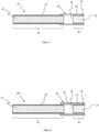
- FIG. 1 shows an aerosol-generating article 10 having an upstream end and a downstream end and comprising a tobacco rod 20 which is attached at its downstream end to an axially aligned filter 30.
- Aerosol-generating article 10 is a cigarette which is configured to be consumed by ignition of the tobacco rod 20.
- the tobacco rod 20 comprises a charge of cut filler 22 that is circumscribed by a tobacco rod wrapper 24.
- the filter 30 comprises a single segment of cellulose acetate tow 32 circumscribed by a filter wrapper 34.
- the aerosol-generating article 10 also comprises a bridging element 40 comprising a single wrapper 42.
- the single wrapper 42 circumscribes the tobacco rod 20 and the filter 30.
- the single wrapper comprises adhesive (not shown in Figure 1 ) to permanently secure the filter 30 to the tobacco rod 20.
- the bridging element 40 has a reflectance factor of 85 percent or higher.
- a cavity 44 is located between the tobacco rod 20 and the filter 30.
- the cavity 44 is delimited by the ends of the tobacco rod 20 and the filter 30 and by the inner surface of the single wrapper 42 of the bridging element 40.
- the inner surface of the single wrapper extends circumferentially around the cavity 44, extending around the complete circumference of the cavity 44.
- the cavity 44 being partially delimited by the single wrapper 42 of the bridging element 40 having a reflectance of 85 percent or higher results in the cavity not being visibly discernible through the bridging element when the aerosol-generating article is viewed from the outside and in normal lighting conditions.
- the cavity 44 has a length of 3 millimeters. In other words, the separation between the tobacco rod 20 and the filter 30 is 3 millimeters.
- FIG 2 shows an aerosol-generating article 100.
- the aerosol-generating article 100 comprises a bridging element 50 comprising a first wrapper 52 and a second wrapper 53.
- the aerosol-generating article 100 is the same as the aerosol-generating article 10 of Figure 1 .
- the first wrapper 52 of the bridging element 50 circumscribes the tobacco rod 20 and the filter 30.
- the first wrapper 52 comprises adhesive (not shown in Figure 2 ) to permanently secure the filter 30 to the tobacco rod 20.
- the second wrapper 53 circumscribes the first wrapper 52.
- the bridging element 50 has a reflectance factor of 85 percent or higher. Both the first wrapper 52 and the second wrapper 53 contribute to the reflectance factor of bridging element 50.
- the cavity located between the tobacco rod 20 and the filter 30 is delimited by the ends of the tobacco rod 20 and the filter 30 and by the inner surface of the first wrapper 52.
- each bridging element 40, 50 of the aerosol-generating articles shown respectively in Figures 1 and 2 it is not necessary for the entire length of each bridging element 40, 50 of the aerosol-generating articles shown respectively in Figures 1 and 2 to have a reflectance factor of 85 percent higher.
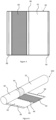
- Figure 3 shows an example of a bridging element where a portion of the bridging element having a reflectance of 85 percent or higher does not extend along the full length of the bridging element.
- Figure 3 shows a bridging element 60 comprising a single wrapper 62.
- the bridging element 60 is shown separately to any aerosol-generating article and from the perspective of the inner surface of the single wrapper 62.
- the bridging element 60 comprises a first portion 64 having a reflectance factor of 85 percent or higher.
- the single wrapper 62 comprises a coating on the inner surface which demarks the first portion 64.
- the coating is printed on to the inner surface of the single wrapper with a coverage density of between 1 and 5 grams per centimetre squared.
- the coating comprises opaque pigments.
- the opaque pigments comprise white and black pigments in a ratio of 80 percent white pigments to 20 percent black pigments.
- the coating also comprises nitrocellulose and an ethanol or ethyl acetate solvent. The coating contributes to the reflectance factor of the first portion 64 being 85 percent or higher.
- the single wrapper 62 also comprises lines of adhesive 66. These lines of adhesive 66 are used to permanently secure the bridging element 60 to a tobacco rod 20 and filter 30.
- Figure 4 shows the bridging element 60 as part of an aerosol-generating article 200 but unwrapped to show the inner surface of the single wrapper 62 with respect to the other features of the aerosol-generating article 200.
- Figure 4 shows how the first portion 64, as demarked by the coating on the inner surface of the single wrapper 62, is aligned with cavity so that the cavity 44 is delimited by the first portion 64 when the aerosol-generating article 200 is fully assembled.
- the cavity 44 has a length of 3 millimeters.
- the first portion 64 extends along the length of the single wrapper 62 by a distance of 7 millimetres. Therefore, the first portion extends along the bridging element 60 by a distance, which is greater than the length of the cavity 44. This ensures that cavity 44 is delimited by the first portion 64 of the bridging element 60 along the entire length of the cavity 44, even if manufacturing tolerances cause the bridging element 60 and the cavity 44 to not be centrally aligned.
- the first portion 64 of the bridging element 60 circumscribes a portion of the tobacco rod 20 and a portion of the filter 30. In a properly aligned aerosol-generating article, the first portion 64 of the bridging element 60 extends a distance of 2 millimetres along the length of the filter and 2 millimetre along the length of the rod.
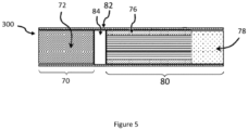
- FIG. 5 shows an aerosol-generating article 300 configured to generate an aerosol by heating rather than burning the aerosol-generating substrate.
- the aerosol-generating article 300 comprises a rod 70 at an upstream end.
- the rod 70 comprises an aerosol-generating substrate 72.
- the aerosol-generating article 300 also comprises a filter 80 at a downstream end.
- the filter 80 comprises an aerosol-cooling element 76 and a segment of filtration material 78 downstream of the aerosol-cooling element 76.
- the filter 80 and rod 70 are in axial alignment with one another and each of the components of the filter 70 are in axial alignment.
- the aerosol-generating article 300 also comprises a bridging element 82 comprising a single wrapper.
- the single wrapper comprises adhesive (not shown in Figure 5 ) to permanently secure the filter 80 to the rod 70.
- the bridging element 82 has a reflectance factor of 85 percent or higher.
- a cavity 84 is located between the rod 70 and the filter 80.
- the cavity 84 is delimited by the ends of the rod 70 and the filter 80 and by the inner surface of the single wrapper of the bridging element 80.
- the inner surface of the single wrapper extends circumferentially around the cavity 84, extending around the complete circumference of the cavity 84.
- the cavity 84 being partially delimited by the single wrapper of the bridging element 82 having a reflectance of 85 percent or higher results in the cavity not being visibly discernible through the bridging element 82 when the aerosol-generating article 300 is viewed from the outside and in normal lighting conditions.
Landscapes
- Engineering & Computer Science (AREA)
- Mechanical Engineering (AREA)
- Cigarettes, Filters, And Manufacturing Of Filters (AREA)
- Nozzles (AREA)
- Containers And Packaging Bodies Having A Special Means To Remove Contents (AREA)
Claims (13)
- Article de génération d'aérosol (10, 100, 200, 300) comprenant :une tige (20, 70) comprenant un substrat de génération d'aérosol (22, 72) ;un filtre (30, 80) en alignement axial avec la tige (20, 70) ;un élément de pontage (40, 50, 60, 82) comprenant une première enveloppe (42, 52, 62), la première enveloppe (42, 52, 62) entourant la tige (20, 70) et le filtre (30, 80) et arrimant le filtre (30, 80) à la tige (20, 70) ; etune cavité (44, 84) située entre la tige (20, 70) et le filtre (30, 80), la cavité (44, 84) étant partiellement délimitée par la surface intérieure de la première enveloppe (42, 52, 62) dans une première portion (64) de l'élément de pontage (40, 50, 60, 82),dans lequel la première portion (64) de l'élément de pontage (40, 50, 60, 82) a un facteur de réflectance de 85 pour cent ou plus ; etdans lequel la surface intérieure de la première enveloppe (42, 52, 62) dans la première portion (64) de l'élément de pontage (40, 50, 60, 82) comprend un revêtement.
- Article de génération d'aérosol (10, 100, 200, 300) selon la revendication 1, dans lequel l'extrémité amont de la cavité (44, 84) est délimitée par la tige (20, 70) et l'extrémité aval de la cavité (44, 84) est délimitée par le filtre (30, 80).
- Article de génération d'aérosol (10, 100, 200, 300) selon la revendication 1 ou 2, dans lequel la cavité (44, 84) a une longueur d'au moins 1 millimètre.
- Article de génération d'aérosol (10, 100, 200, 300) selon l'une quelconque des revendications précédentes, dans lequel la première portion (64) de l'élément de pontage (40, 50, 60, 82) s'étend le long de la longueur de l'élément de pontage (40, 50, 60, 82) sur une distance d'au moins 1,2 fois la longueur de la cavité (44, 84).
- Article de génération d'aérosol (10, 100, 200, 300) selon l'une quelconque des revendications précédentes, dans lequel la première portion (64) de l'élément de pontage (40, 50, 60, 82) s'étend sur une distance d'entre 4 millimètres et 10 millimètres le long de la longueur de l'élément de pontage (40, 50, 60, 82).
- Article de génération d'aérosol (10, 100, 200, 300) selon l'une quelconque des revendications précédentes, dans lequel le filtre (30, 80) est entouré par la première portion (64) de l'élément de pontage (40, 50, 60, 82).
- Article de génération d'aérosol (10, 100, 200, 300) selon la revendication 6, dans lequel la première portion (64) de l'élément de pontage (40, 50, 60, 82) s'étend le long d'au moins 1 millimètre de la longueur du filtre (30, 80).
- Article de génération d'aérosol (10, 200, 300) selon l'une quelconque des revendications précédentes, dans lequel l'élément de pontage (40, 60, 82) comprend une enveloppe (42, 62) unique.
- Article de génération d'aérosol (100) selon l'une quelconque des revendications 1 à 7, dans lequel l'élément de pontage (50) comprend une deuxième enveloppe (53) entourant la première enveloppe (52).
- Article de génération d'aérosol (10, 100, 200, 300) selon l'une quelconque des revendications précédentes, dans lequel la surface intérieure de la première enveloppe (42, 52, 62) dans la première portion de l'élément de pontage (40, 50, 60, 82) s'étend circonférentiellement autour de la cavité sur une distance supérieure à 5 millimètres.
- Article de génération d'aérosol (10, 100, 200, 300) selon l'une quelconque des revendications précédentes, dans lequel la surface intérieure de la première enveloppe (42, 52, 62) de la première portion (64) de l'élément de pontage (40, 50, 60, 82) a une aire surfacique supérieure à 25 millimètres carrés.
- Récipient comprenant une pluralité d'articles de génération d'aérosol (10, 100, 200, 300), dans lequel au moins 50 pour cent des articles de génération d'aérosol dans le récipient sont des articles de génération d'aérosol (10, 100, 200, 300) selon l'une quelconque des revendications 1 à 11.
- Procédé de fabrication d'un article de génération d'aérosol (10, 100, 200, 300) comprenant :la fourniture d'une tige (20, 70) comprenant un substrat de génération d'aérosol (22, 72) ;la fourniture d'un filtre (30, 80) ;la fourniture d'un élément de pontage (40, 50, 60, 82) comprenant une première enveloppe (42, 52, 62) ; etl'arrimage du filtre (30, 80) à la tige (20, 70) à l'aide de l'élément de pontage (40, 50, 60, 82) de sorte que la première enveloppe (42, 52, 62) entoure la tige (20, 70) et le filtre (30, 80) dans une relation espacée pour former une cavité entre la tige (20, 70) et le filtre (30, 80), la cavité étant partiellement délimitée par la première surface intérieure de la première enveloppe (42, 52, 62) dans une première portion de l'élément de pontage (40, 50, 60 ,82),dans lequel la première portion (64) de l'élément de pontage (40, 50, 60, 82) a un facteur de réflectance de 85 pour cent ou plus ; etdans lequel la surface intérieure de la première enveloppe (42, 52, 62) dans la première portion (64) de l'élément de pontage (40, 50, 60, 82) comprend un revêtement.
Applications Claiming Priority (2)
| Application Number | Priority Date | Filing Date | Title |
|---|---|---|---|
| EP20158546 | 2020-02-20 | ||
| PCT/EP2021/054221 WO2021165502A2 (fr) | 2020-02-20 | 2021-02-19 | Article de génération d'aérosol ayant un élément de pontage à facteur de réflectance |
Publications (3)
| Publication Number | Publication Date |
|---|---|
| EP4106558A2 EP4106558A2 (fr) | 2022-12-28 |
| EP4106558B1 true EP4106558B1 (fr) | 2024-04-03 |
| EP4106558C0 EP4106558C0 (fr) | 2024-04-03 |
Family
ID=69723822
Family Applications (1)
| Application Number | Title | Priority Date | Filing Date |
|---|---|---|---|
| EP21705229.9A Active EP4106558B1 (fr) | 2020-02-20 | 2021-02-19 | Article de génération d'aérosol ayant un élément de pontage comportant un facteur de réflectance |
Country Status (7)
| Country | Link |
|---|---|
| US (1) | US12564212B2 (fr) |
| EP (1) | EP4106558B1 (fr) |
| JP (2) | JP2023515930A (fr) |
| KR (1) | KR20220143698A (fr) |
| CN (1) | CN115135178A (fr) |
| BR (1) | BR112022016260A2 (fr) |
| WO (1) | WO2021165502A2 (fr) |
Families Citing this family (1)
| Publication number | Priority date | Publication date | Assignee | Title |
|---|---|---|---|---|
| WO2022167495A1 (fr) | 2021-02-02 | 2022-08-11 | Philip Morris Products S.A. | Article de génération d'aérosol avec segments de bouchon entourant un élément de génération d'aérosol |
Family Cites Families (36)
| Publication number | Priority date | Publication date | Assignee | Title |
|---|---|---|---|---|
| US3065756A (en) | 1959-08-01 | 1962-11-27 | Davies James Noel | Tobacco smoking device |
| US3064541A (en) | 1959-12-01 | 1962-11-20 | Mantchev Marco Ivanov | Machine for making filter units for cigarettes |
| US3283762A (en) | 1964-05-14 | 1966-11-08 | Michael S Kissel | Aeratable cigarette |
| IT1149414B (it) | 1981-01-15 | 1986-12-03 | Cigarette Components Ltd | Filtro per sigaretta |
| GB8531660D0 (en) * | 1985-12-23 | 1986-02-05 | British American Tobacco Co | Smoking articles |
| EP0275379B1 (fr) | 1986-12-05 | 1991-03-13 | Audi Ag | Antenne télescopique à déploiement manuel |
| US4776354A (en) | 1987-01-02 | 1988-10-11 | R. J. Reynolds Tobacco Company | Filtered smoking article |
| DE69300056T2 (de) * | 1993-07-06 | 1995-08-10 | Fabriques De Tabac Reunies S.A., Neuenburg/Neuchatel | Mit mehr als einer Öffnungsmöglichkeit versehene Zigarettenverpackung. |
| JP3108906B2 (ja) | 1995-05-16 | 2000-11-13 | 株式会社クボタ | エンジン作業機の始動制御装置 |
| US7836895B2 (en) | 2003-06-23 | 2010-11-23 | R. J. Reynolds Tobacco Company | Filtered cigarette incorporating a breakable capsule |
| JP3108906U (ja) * | 2004-11-22 | 2005-04-28 | 和彦 川本 | ライタ入りシガレットケース |
| BRPI0603954B1 (pt) | 2006-09-25 | 2014-05-20 | Souza Cruz Sa | Artigo para fumar e método de fabricação de um artigo para fumar |
| GB0716629D0 (en) * | 2007-08-24 | 2007-10-03 | British American Tobacco Co | Tipping paper |
| JP2012507287A (ja) * | 2008-10-31 | 2012-03-29 | アール・ジエイ・レイノルズ・タバコ・カンパニー | フィルタ付き紙巻タバコ用のチッピング材 |
| EP2253233A1 (fr) | 2009-05-21 | 2010-11-24 | Philip Morris Products S.A. | Système de fumage chauffé électriquement |
| WO2011117750A2 (fr) * | 2010-03-26 | 2011-09-29 | Philip Morris Products S.A. | Article pour fumeur avec un matériau de feuille thermorésistant |
| EP2579736B8 (fr) | 2010-06-10 | 2020-02-26 | Essentra Filter Products Development Co. Pte. Ltd. | Filtre pour la fumée de tabac |
| US8950407B2 (en) * | 2010-06-30 | 2015-02-10 | R.J. Reynolds Tobacco Company | Degradable adhesive compositions for smoking articles |
| WO2012061249A2 (fr) * | 2010-11-02 | 2012-05-10 | Greenbutts Llc | Filtre de cigarette ayant une enveloppe modifiée |
| CN103702577B (zh) * | 2011-08-05 | 2015-04-29 | 日本烟草产业株式会社 | 香烟 |
| JP2015033330A (ja) * | 2011-11-30 | 2015-02-19 | 日本たばこ産業株式会社 | 喫煙物品用フィルターおよび喫煙物品 |
| WO2013179428A1 (fr) * | 2012-05-30 | 2013-12-05 | 日本たばこ産業株式会社 | Cigarette et éléments d'emballage |
| EP3003904B1 (fr) * | 2013-06-03 | 2018-12-26 | Essentra Filter Products Development Co. Pte. Ltd | Distributeur et son procédé de fabrication |
| KR102215329B1 (ko) | 2013-07-16 | 2021-02-16 | 필립모리스 프로덕츠 에스.에이. | 소화를 용이하게 하는 흡연 물품 필터 |
| SG11201600359PA (en) * | 2013-07-19 | 2016-02-26 | Philip Morris Products Sa | Smoking article having a particle containing wrapper |
| EP2888955A1 (fr) * | 2013-12-24 | 2015-07-01 | Philip Morris Products S.A. | Article à fumer présentant une partie enveloppe de bout-filtre amovible |
| CN104921296A (zh) | 2015-06-25 | 2015-09-23 | 云南中烟工业有限责任公司 | 一种用于加热不燃烧型卷烟的复合嘴棒 |
| TW201700019A (zh) | 2015-06-30 | 2017-01-01 | 菲利浦莫里斯製品股份有限公司 | 具有改良的熄滅性的菸製品 |
| WO2017013105A1 (fr) * | 2015-07-22 | 2017-01-26 | Jt International Sa | Article à fumer |
| RU2713242C1 (ru) * | 2015-12-30 | 2020-02-04 | Филип Моррис Продактс С.А. | Выдвижной источник теплоты для изделия, генерирующего аэрозоль |
| CN206326967U (zh) * | 2016-12-01 | 2017-07-14 | 江苏大亚新型包装材料有限公司 | 局部透明接装纸 |
| AU2018377970B2 (en) * | 2017-11-30 | 2024-03-07 | Philip Morris Products S.A. | Aerosol-generating article having mouthpiece with upstream cavity |
| KR20200094772A (ko) * | 2017-12-22 | 2020-08-07 | 니뽄 다바코 산교 가부시키가이샤 | 흡연 물품 및 흡연 물품의 필터 |
| TWM557523U (zh) * | 2017-12-22 | 2018-04-01 | Xie ming long | 香菸結構改良 |
| CN107981411A (zh) | 2017-12-28 | 2018-05-04 | 浙江中烟工业有限责任公司 | 一种加热不燃烧卷烟烟支 |
| GB2574790A (en) * | 2018-04-24 | 2019-12-25 | British American Tobacco Investments Ltd | A tobacco industry product component and a method of manufacturing a tobacco industry product component |
-
2021
- 2021-02-19 CN CN202180015607.5A patent/CN115135178A/zh active Pending
- 2021-02-19 EP EP21705229.9A patent/EP4106558B1/fr active Active
- 2021-02-19 BR BR112022016260A patent/BR112022016260A2/pt unknown
- 2021-02-19 JP JP2022549926A patent/JP2023515930A/ja active Pending
- 2021-02-19 US US17/800,606 patent/US12564212B2/en active Active
- 2021-02-19 KR KR1020227031520A patent/KR20220143698A/ko active Pending
- 2021-02-19 WO PCT/EP2021/054221 patent/WO2021165502A2/fr not_active Ceased
-
2026
- 2026-01-05 JP JP2026000456A patent/JP2026040797A/ja active Pending
Also Published As
| Publication number | Publication date |
|---|---|
| CN115135178A (zh) | 2022-09-30 |
| WO2021165502A3 (fr) | 2021-10-07 |
| US20230292816A1 (en) | 2023-09-21 |
| JP2023515930A (ja) | 2023-04-17 |
| WO2021165502A2 (fr) | 2021-08-26 |
| EP4106558A2 (fr) | 2022-12-28 |
| JP2026040797A (ja) | 2026-03-09 |
| US12564212B2 (en) | 2026-03-03 |
| BR112022016260A2 (pt) | 2022-10-11 |
| KR20220143698A (ko) | 2022-10-25 |
| EP4106558C0 (fr) | 2024-04-03 |
Similar Documents
| Publication | Publication Date | Title |
|---|---|---|
| KR102676028B1 (ko) | 섬유상 필터 부위를 갖는 에어로졸 발생 물품 | |
| KR102104277B1 (ko) | 개선된 최외곽 래퍼를 갖는 에어로졸 발생 물품 | |
| US20210022390A1 (en) | Smoking article | |
| AU2018373559C1 (en) | Smoking article | |
| TW202133748A (zh) | 過濾器、吸煙物品及香味吸嚐物品 | |
| JP2026040797A (ja) | 反射係数を有するブリッジング要素を有するエアロゾル発生物品 | |
| CN114144080A (zh) | 具有保持件的气溶胶生成制品 | |
| EP4106559B1 (fr) | Article de génération d'aérosol doté d'un élément de pontage à poids de base | |
| WO2016050883A1 (fr) | Article à fumer comprenant une bande destinée à être fixée sur le bout | |
| RU2833150C1 (ru) | Изделие, генерирующее аэрозоль, емкость для изделий, генерирующих аэрозоль, и способ изготовления изделия, генерирующего аэрозоль | |
| AU2019431538B2 (en) | Smoking article | |
| HK40083340A (en) | Aerosol-generating article having bridging element with basis weight | |
| HK40083340B (en) | Aerosol-generating article having bridging element with basis weight | |
| RU2830560C1 (ru) | Изделие, генерирующее аэрозоль, контейнер для изделий, генерирующих аэрозоль, и способ изготовления изделия, генерирующего аэрозоль | |
| CA3131572C (fr) | Article à fumer | |
| JP2025528594A (ja) | エアロゾル発生物品のための吸湿ラッパー | |
| TR2021013512U2 (tr) | Tütün ürünü | |
| HK1234964B (en) | Smoking article with over-tipping band |
Legal Events
| Date | Code | Title | Description |
|---|---|---|---|
| STAA | Information on the status of an ep patent application or granted ep patent |
Free format text: STATUS: UNKNOWN |
|
| STAA | Information on the status of an ep patent application or granted ep patent |
Free format text: STATUS: THE INTERNATIONAL PUBLICATION HAS BEEN MADE |
|
| PUAI | Public reference made under article 153(3) epc to a published international application that has entered the european phase |
Free format text: ORIGINAL CODE: 0009012 |
|
| STAA | Information on the status of an ep patent application or granted ep patent |
Free format text: STATUS: REQUEST FOR EXAMINATION WAS MADE |
|
| 17P | Request for examination filed |
Effective date: 20220819 |
|
| AK | Designated contracting states |
Kind code of ref document: A2 Designated state(s): AL AT BE BG CH CY CZ DE DK EE ES FI FR GB GR HR HU IE IS IT LI LT LU LV MC MK MT NL NO PL PT RO RS SE SI SK SM TR |
|
| DAV | Request for validation of the european patent (deleted) | ||
| DAX | Request for extension of the european patent (deleted) | ||
| GRAP | Despatch of communication of intention to grant a patent |
Free format text: ORIGINAL CODE: EPIDOSNIGR1 |
|
| STAA | Information on the status of an ep patent application or granted ep patent |
Free format text: STATUS: GRANT OF PATENT IS INTENDED |
|
| INTG | Intention to grant announced |
Effective date: 20231025 |
|
| GRAS | Grant fee paid |
Free format text: ORIGINAL CODE: EPIDOSNIGR3 |
|
| GRAA | (expected) grant |
Free format text: ORIGINAL CODE: 0009210 |
|
| STAA | Information on the status of an ep patent application or granted ep patent |
Free format text: STATUS: THE PATENT HAS BEEN GRANTED |
|
| AK | Designated contracting states |
Kind code of ref document: B1 Designated state(s): AL AT BE BG CH CY CZ DE DK EE ES FI FR GB GR HR HU IE IS IT LI LT LU LV MC MK MT NL NO PL PT RO RS SE SI SK SM TR |
|
| REG | Reference to a national code |
Ref country code: CH Ref legal event code: EP |
|
| REG | Reference to a national code |
Ref country code: DE Ref legal event code: R096 Ref document number: 602021011277 Country of ref document: DE |
|
| REG | Reference to a national code |
Ref country code: IE Ref legal event code: FG4D |
|
| U01 | Request for unitary effect filed |
Effective date: 20240403 |
|
| U07 | Unitary effect registered |
Designated state(s): AT BE BG DE DK EE FI FR IT LT LU LV MT NL PT SE SI Effective date: 20240408 |
|
| U1N | Appointed representative for the unitary patent procedure changed after the registration of the unitary effect |
Representative=s name: REDDIE & GROSE LLP; GB |
|
| PG25 | Lapsed in a contracting state [announced via postgrant information from national office to epo] |
Ref country code: IS Free format text: LAPSE BECAUSE OF FAILURE TO SUBMIT A TRANSLATION OF THE DESCRIPTION OR TO PAY THE FEE WITHIN THE PRESCRIBED TIME-LIMIT Effective date: 20240803 |
|
| PG25 | Lapsed in a contracting state [announced via postgrant information from national office to epo] |
Ref country code: HR Free format text: LAPSE BECAUSE OF FAILURE TO SUBMIT A TRANSLATION OF THE DESCRIPTION OR TO PAY THE FEE WITHIN THE PRESCRIBED TIME-LIMIT Effective date: 20240403 |
|
| PG25 | Lapsed in a contracting state [announced via postgrant information from national office to epo] |
Ref country code: GR Free format text: LAPSE BECAUSE OF FAILURE TO SUBMIT A TRANSLATION OF THE DESCRIPTION OR TO PAY THE FEE WITHIN THE PRESCRIBED TIME-LIMIT Effective date: 20240704 |
|
| PG25 | Lapsed in a contracting state [announced via postgrant information from national office to epo] |
Ref country code: ES Free format text: LAPSE BECAUSE OF FAILURE TO SUBMIT A TRANSLATION OF THE DESCRIPTION OR TO PAY THE FEE WITHIN THE PRESCRIBED TIME-LIMIT Effective date: 20240403 |
|
| PG25 | Lapsed in a contracting state [announced via postgrant information from national office to epo] |
Ref country code: CZ Free format text: LAPSE BECAUSE OF FAILURE TO SUBMIT A TRANSLATION OF THE DESCRIPTION OR TO PAY THE FEE WITHIN THE PRESCRIBED TIME-LIMIT Effective date: 20240403 |
|
| PG25 | Lapsed in a contracting state [announced via postgrant information from national office to epo] |
Ref country code: PL Free format text: LAPSE BECAUSE OF FAILURE TO SUBMIT A TRANSLATION OF THE DESCRIPTION OR TO PAY THE FEE WITHIN THE PRESCRIBED TIME-LIMIT Effective date: 20240403 |
|
| PG25 | Lapsed in a contracting state [announced via postgrant information from national office to epo] |
Ref country code: PL Free format text: LAPSE BECAUSE OF FAILURE TO SUBMIT A TRANSLATION OF THE DESCRIPTION OR TO PAY THE FEE WITHIN THE PRESCRIBED TIME-LIMIT Effective date: 20240403 Ref country code: NO Free format text: LAPSE BECAUSE OF FAILURE TO SUBMIT A TRANSLATION OF THE DESCRIPTION OR TO PAY THE FEE WITHIN THE PRESCRIBED TIME-LIMIT Effective date: 20240703 Ref country code: IS Free format text: LAPSE BECAUSE OF FAILURE TO SUBMIT A TRANSLATION OF THE DESCRIPTION OR TO PAY THE FEE WITHIN THE PRESCRIBED TIME-LIMIT Effective date: 20240803 Ref country code: HR Free format text: LAPSE BECAUSE OF FAILURE TO SUBMIT A TRANSLATION OF THE DESCRIPTION OR TO PAY THE FEE WITHIN THE PRESCRIBED TIME-LIMIT Effective date: 20240403 Ref country code: GR Free format text: LAPSE BECAUSE OF FAILURE TO SUBMIT A TRANSLATION OF THE DESCRIPTION OR TO PAY THE FEE WITHIN THE PRESCRIBED TIME-LIMIT Effective date: 20240704 Ref country code: ES Free format text: LAPSE BECAUSE OF FAILURE TO SUBMIT A TRANSLATION OF THE DESCRIPTION OR TO PAY THE FEE WITHIN THE PRESCRIBED TIME-LIMIT Effective date: 20240403 Ref country code: CZ Free format text: LAPSE BECAUSE OF FAILURE TO SUBMIT A TRANSLATION OF THE DESCRIPTION OR TO PAY THE FEE WITHIN THE PRESCRIBED TIME-LIMIT Effective date: 20240403 Ref country code: RS Free format text: LAPSE BECAUSE OF FAILURE TO SUBMIT A TRANSLATION OF THE DESCRIPTION OR TO PAY THE FEE WITHIN THE PRESCRIBED TIME-LIMIT Effective date: 20240703 |
|
| REG | Reference to a national code |
Ref country code: DE Ref legal event code: R097 Ref document number: 602021011277 Country of ref document: DE |
|
| PG25 | Lapsed in a contracting state [announced via postgrant information from national office to epo] |
Ref country code: RO Free format text: LAPSE BECAUSE OF FAILURE TO SUBMIT A TRANSLATION OF THE DESCRIPTION OR TO PAY THE FEE WITHIN THE PRESCRIBED TIME-LIMIT Effective date: 20240403 Ref country code: SK Free format text: LAPSE BECAUSE OF FAILURE TO SUBMIT A TRANSLATION OF THE DESCRIPTION OR TO PAY THE FEE WITHIN THE PRESCRIBED TIME-LIMIT Effective date: 20240403 |
|
| PG25 | Lapsed in a contracting state [announced via postgrant information from national office to epo] |
Ref country code: SM Free format text: LAPSE BECAUSE OF FAILURE TO SUBMIT A TRANSLATION OF THE DESCRIPTION OR TO PAY THE FEE WITHIN THE PRESCRIBED TIME-LIMIT Effective date: 20240403 |
|
| PG25 | Lapsed in a contracting state [announced via postgrant information from national office to epo] |
Ref country code: SM Free format text: LAPSE BECAUSE OF FAILURE TO SUBMIT A TRANSLATION OF THE DESCRIPTION OR TO PAY THE FEE WITHIN THE PRESCRIBED TIME-LIMIT Effective date: 20240403 Ref country code: SK Free format text: LAPSE BECAUSE OF FAILURE TO SUBMIT A TRANSLATION OF THE DESCRIPTION OR TO PAY THE FEE WITHIN THE PRESCRIBED TIME-LIMIT Effective date: 20240403 Ref country code: RO Free format text: LAPSE BECAUSE OF FAILURE TO SUBMIT A TRANSLATION OF THE DESCRIPTION OR TO PAY THE FEE WITHIN THE PRESCRIBED TIME-LIMIT Effective date: 20240403 |
|
| PLBE | No opposition filed within time limit |
Free format text: ORIGINAL CODE: 0009261 |
|
| STAA | Information on the status of an ep patent application or granted ep patent |
Free format text: STATUS: NO OPPOSITION FILED WITHIN TIME LIMIT |
|
| 26N | No opposition filed |
Effective date: 20250106 |
|
| U20 | Renewal fee for the european patent with unitary effect paid |
Year of fee payment: 5 Effective date: 20250221 |
|
| PG25 | Lapsed in a contracting state [announced via postgrant information from national office to epo] |
Ref country code: MC Free format text: LAPSE BECAUSE OF FAILURE TO SUBMIT A TRANSLATION OF THE DESCRIPTION OR TO PAY THE FEE WITHIN THE PRESCRIBED TIME-LIMIT Effective date: 20240403 |
|
| PG25 | Lapsed in a contracting state [announced via postgrant information from national office to epo] |
Ref country code: IE Free format text: LAPSE BECAUSE OF NON-PAYMENT OF DUE FEES Effective date: 20250219 |
|
| REG | Reference to a national code |
Ref country code: CH Ref legal event code: U11 Free format text: ST27 STATUS EVENT CODE: U-0-0-U10-U11 (AS PROVIDED BY THE NATIONAL OFFICE) Effective date: 20260301 |
|
| U20 | Renewal fee for the european patent with unitary effect paid |
Year of fee payment: 6 Effective date: 20260225 |
|
| PGFP | Annual fee paid to national office [announced via postgrant information from national office to epo] |
Ref country code: GB Payment date: 20260220 Year of fee payment: 6 |
|
| PGFP | Annual fee paid to national office [announced via postgrant information from national office to epo] |
Ref country code: CH Payment date: 20260301 Year of fee payment: 6 |