EP4106559B1 - Article de génération d'aérosol doté d'un élément de pontage à poids de base - Google Patents
Article de génération d'aérosol doté d'un élément de pontage à poids de base Download PDFInfo
- Publication number
- EP4106559B1 EP4106559B1 EP21705230.7A EP21705230A EP4106559B1 EP 4106559 B1 EP4106559 B1 EP 4106559B1 EP 21705230 A EP21705230 A EP 21705230A EP 4106559 B1 EP4106559 B1 EP 4106559B1
- Authority
- EP
- European Patent Office
- Prior art keywords
- aerosol
- bridging element
- wrapper
- filter
- rod
- Prior art date
- Legal status (The legal status is an assumption and is not a legal conclusion. Google has not performed a legal analysis and makes no representation as to the accuracy of the status listed.)
- Active
Links
Images


Classifications
-
- A—HUMAN NECESSITIES
- A24—TOBACCO; CIGARS; CIGARETTES; SIMULATED SMOKING DEVICES; SMOKERS' REQUISITES
- A24D—CIGARS; CIGARETTES; TOBACCO SMOKE FILTERS; MOUTHPIECES OF CIGARS OR CIGARETTES; MANUFACTURE OF TOBACCO SMOKE FILTERS OR MOUTHPIECES
- A24D1/00—Cigars; Cigarettes
- A24D1/02—Cigars; Cigarettes with special covers
-
- A—HUMAN NECESSITIES
- A24—TOBACCO; CIGARS; CIGARETTES; SIMULATED SMOKING DEVICES; SMOKERS' REQUISITES
- A24C—MACHINES FOR MAKING CIGARS OR CIGARETTES
- A24C5/00—Making cigarettes; Making tipping materials for, or attaching filters or mouthpieces to, cigars or cigarettes
- A24C5/56—Making tipping materials, e.g. sheet cork for mouthpieces of cigars or cigarettes, by mechanical means
-
- A—HUMAN NECESSITIES
- A24—TOBACCO; CIGARS; CIGARETTES; SIMULATED SMOKING DEVICES; SMOKERS' REQUISITES
- A24D—CIGARS; CIGARETTES; TOBACCO SMOKE FILTERS; MOUTHPIECES OF CIGARS OR CIGARETTES; MANUFACTURE OF TOBACCO SMOKE FILTERS OR MOUTHPIECES
- A24D1/00—Cigars; Cigarettes
- A24D1/20—Cigarettes specially adapted for simulated smoking devices
-
- A—HUMAN NECESSITIES
- A24—TOBACCO; CIGARS; CIGARETTES; SIMULATED SMOKING DEVICES; SMOKERS' REQUISITES
- A24C—MACHINES FOR MAKING CIGARS OR CIGARETTES
- A24C5/00—Making cigarettes; Making tipping materials for, or attaching filters or mouthpieces to, cigars or cigarettes
- A24C5/56—Making tipping materials, e.g. sheet cork for mouthpieces of cigars or cigarettes, by mechanical means
- A24C5/58—Applying the tipping materials
- A24C5/586—Applying the tipping materials to a cigarette
-
- A—HUMAN NECESSITIES
- A24—TOBACCO; CIGARS; CIGARETTES; SIMULATED SMOKING DEVICES; SMOKERS' REQUISITES
- A24D—CIGARS; CIGARETTES; TOBACCO SMOKE FILTERS; MOUTHPIECES OF CIGARS OR CIGARETTES; MANUFACTURE OF TOBACCO SMOKE FILTERS OR MOUTHPIECES
- A24D1/00—Cigars; Cigarettes
- A24D1/04—Cigars; Cigarettes with mouthpieces or filter-tips
- A24D1/045—Cigars; Cigarettes with mouthpieces or filter-tips with smoke filter means
Definitions
- the present disclosure relates to aerosol-generating articles, for example cigarettes or heated aerosol-generating articles.
- Filter cigarettes typically comprise a rod of aerosol-generating substrate in the form of tobacco cut filler surrounded by a paper wrapper and a cylindrical filter aligned in an end-to-end relationship with the wrapped tobacco rod, with the filter attached to the tobacco rod by tipping paper.
- the filter may consist of a plug of cellulose acetate tow wrapped in porous plug wrap.
- Filter cigarettes with multi-component filters that comprise two or more segments of filtration material for the removal of particulate and gaseous components of the mainstream smoke are also known.
- a consumer smokes a cigarette until the burning area of the tobacco rod (the lit end) reaches the edge of the tipping paper. At this point, the proximity of the burning area to the filter can result in burning or excessive heating of the filter which can negatively affect the taste and flavour of the mainstream smoke produced by the cigarette.
- Aerosol-generating articles for the generation of an aerosol by heating rather than burning are known in the art.
- One example of such aerosol-generating articles comprises an aerosol-generating substrate penetrable by a heating element of an aerosol-generating device.
- the aerosol-generating substrate is, preferably, a solid substrate and comprises tobacco.
- the heating element heats the aerosol-generating substrate to generate an aerosol that a user can draw through a filter at the mouth end of the aerosol-generating article.
- the aerosol-generating substrate may be heatable by a susceptor.
- the aerosol-generating device may comprise an inductor coil through which an alternating current is passed to generate an alternating magnetic field.
- the susceptor may be a part of the aerosol-generating article or a part of the aerosol-generating device.
- the aerosol-generating substrate may be heated to temperatures of around 300 degrees Celsius or more. As a result, in such arrangements, it may also be desirable to avoid excessive heating of the filter.
- US 5 439 011 A discloses a coaxial filter cigarette comprising a rod portion.
- the rod portion has an inner core of a material smouldering substantially residue-free, in particular tobacco material.
- the cigarette further comprises a coaxial filter element.
- the coaxial filter element has a filter core comprising a preferably air-impermeable wrapper.
- a filter jacket coaxially surrounds the filter core and its wrapper.
- the filter jacket comprises an air-impermeable wrapper serving also to connect the rod portion and the filter element.
- the filter jacket is connected by the air-impermeable wrapper to the rod portion in such a manner that between the filter-side end of the rod portion and the tobacco-side end of the filter element a cavity results which forms a smoke mixing zone.
- an aerosol-generating article comprises: a rod comprising an aerosol-generating substrate; a filter in axial alignment with the rod; a bridging element comprising a first wrapper, the first wrapper circumscribing the rod and the filter and securing the filter to the rod; and a cavity located between the rod and the filter, the cavity being partially delimited by the inner surface of the first wrapper in a first portion of the bridging element, wherein the first portion of the bridging element has a basis weight of 50 grams per square meter or greater.
- the provision of a cavity between the rod and filter advantageously reduces the risk of excessive heating or burning of the filter when the aerosol-generating article is consumed.
- the aerosol-generating article may be consumed as a result of ignition of the aerosol-generating substrate.
- the provision of a cavity between the rod comprising the aerosol-generating substrate and the filter reduces the proximity of the burning area of the aerosol-generating substrate to the filter, even when the burning area reaches the end of the rod.
- the aerosol-generating article may be consumed by heating, rather than burning, the aerosol-generating substrate.
- the provision of a cavity between the rod comprising the aerosol-generating substrate and the filter ensures that the filter is not excessively heated.
- a bridging element comprising a first wrapper that secures the filter and the rod and which has an inner surface that partially delimits the cavity may result in an aerosol-generating article that is simple and cheap to manufacture.
- the aerosol-generating article may experience forces, for example compressive or shear forces, during use or during the manufacturing process.
- the bridging element preferably has the strength to withstand such forces.
- Longitudinal forces being applied along the length of the aerosol-generating article may be a particular problem when inserting aerosol-generating articles into packaging during the manufacture process. Longitudinal forces being applied along the length of the aerosol-generating article may also be a particular problem for aerosol-generating articles configured to be consumed by heating rather than burning. Such aerosol-generating articles may be inserted into an aerosol-generating device. This may result in longitudinal forces being applied along the length of the aerosol-generating article on insertion into an aerosol-generating device.
- the first portion of the bridging element is a portion having a basis weight of 50 grams per square meter or greater.
- the bridging element comprises a first wrapper.
- the first wrapper may have a portion having a basis weight of 50 grams per square meter or greater. This portion of the first wrapper may correspond to the first portion of the wrapper.
- the bridging element may comprise more than one wrapper.
- the bridging element may comprise a portion of a first wrapper and a portion of a second wrapper.
- the second wrapper may circumscribe the first wrapper.
- the portion having a basis weight of 50 grams per square meter or greater may be a result of the combined basis weight of two or more layers.
- the cavity may be partially delimited by the inner surface of the first wrapper in the first portion of the bridging element.
- Providing a first portion of the bridging element having a basis weight of 50 grams per square meter or greater can provide strength to the aerosol-generating article in the region of the cavity.
- a basis weight may advantageously be high enough to prevent the cavity from collapsing in normal use of the aerosol-generating article and during the manufacturing process.
- the inner surface of first wrapper in the first portion of the bridging element may extend around extend around the some or all of the circumference of the cavity to prevent collapse of the cavity during normal use of the aerosol-generating article and during the manufacturing process.
- Basis weight is a measure of mass, in grams per square meter. In other words, basis weight is a measure of areal density. Basis weight may also be referred to grammage.
- the first portion of bridging element has a basis weight of between 50 to 110 grams per square meter.
- the first portion of bridging element may have a basis weight of 70 grams per square meter or greater.
- the bridging element may have a basis weight of 80, 90 or even 100 grams per square meter or greater.
- the bridging element may have a basis weight of between 70 to 110 grams per square meter, between 80 to 110 grams per square meter, between 90 to 110 grams per square meter or between 100 and 110 grams per square meter.
- the terms 'upstream' and 'downstream' are used to describe the relative positions of elements, or portions of elements, of the aerosol-generating article in relation to the direction in which a user draws on the aerosol-generating article during use thereof.
- the term "inner surface of the bridging element” is used to describe the surface of the bridging element that faces towards the inside of aerosol-generating article.
- the first portion of the bridging element may have a thickness of between 50 micrometres and 140 micrometres.
- the first portion of the bridging element may have a thickness of between 70 micrometres and 140 micrometres. Preferably, the thickness is 80 micrometres.
- the upstream end of the cavity may be delimited by the rod.
- the downstream end of the cavity may be delimited by the filter.
- the cavity may have a length of at least 1 millimetre. Such a length of cavity can reduce the transfer of heat produced upstream of the cavity to the filter, whether such heat is produced by the ignited aerosol-generating substrate or by the heater of an aerosol-generating device.
- the cavity may reduce heat transfer such that excessive heating of the filter is avoided.
- the cavity may have a length of between 1 millimetre and 7 millimetres.
- the cavity may have a length of at least 2 millimetres.
- the cavity may have a length of between 2 millimetres and 5 millimetres. Even more preferably, the cavity may have a length of 3 millimetres.
- the cavity may have a length of at least 3 millimetres.
- the bridging element may have a length of greater than 25 millimetres. Such a bridging element may be sufficiently long to span the cavity and to circumscribe at least a sufficient portion of each of the rod and the filter. The bridging element may circumscribe the filter along the entire length of the filter. The bridging element may have a length of between 25 millimetres and 40 millimetres. The bridging element may have a length of between 25 millimetres and 30 millimetres.
- the first portion of the bridging element may extend along the length of the bridging element by a distance of at least 1.2 times the length of the cavity.
- the first portion of the bridging element may extend along the length of the bridging element by a distance of at least 1.5 times the length of the cavity.
- the inner surface of the first wrapper partially delimits the cavity regardless of the position of the first portion of the bridging element relative to the cavity.
- the first portion the bridging element may extend a distance of between 4 millimetres and 10 millimetres along the length of the bridging element.
- the rod may be circumscribed by the first portion of the bridging element.
- the first portion of the bridging element may extend along at least 2 millimetres of the length of the rod.
- the first portion of the bridging element may extend along between 2 millimetres and 7 millimetres of the length of the rod.
- the first portion of the bridging element may extend along the entire length of the rod.
- the first wrapper may permanently secure the rod to the filter.
- the first wrapper of the bridging element may comprise an adhesive to permanently secure the filter to the rod.
- the inner surface of the first wrapper of the bridging element may comprise adhesive to permanently secure the first wrapper to the filter.
- the inner surface of the first wrapper of the bridging element may comprise adhesive to permanently secure the first wrapper to the rod.
- the first wrapper may be glued to the rod.
- the first wrapper may be glued to the filter.
- the filter may be circumscribed by the first portion of the bridging element.
- the first portion of the bridging element extends beyond the cavity, along the length of the aerosol-generating article, to circumscribe the filter.
- the portion of bridging element having a basis weight of 50 grams per square meter or greater extends beyond the cavity.
- the first portion of the bridging element may extend along at least 1 millimetre of the length of the filter.
- the first portion of the bridging element may extend along the entire length of the filter.
- the rod may be circumscribed by the first portion of the bridging element.
- the first portion of the bridging element may extend beyond the cavity, along the length of the aerosol-generating article, to circumscribe the rod.
- the portion of bridging element having a basis weight of 50 grams per square meter or greater extends beyond the cavity.
- the first portion of the bridging element may extend along the length of the rod by a distance of at least 2 millimetres.
- the first portion of the bridging element may extend along the length of the rod by a distance of between 2 millimetres and 7 millimetres.
- the first portion of the bridging element may extend along the entire length of the rod.
- the first wrapper may comprise at least one of a cellulose based material, paper, cardboard, reconstituted tobacco or a cellulose based film.
- a cellulose based material having a basis weight of 50 grams per square meter or greater have a suitable stiffness so as to prevent the cavity from collapsing during normal use of the aerosol-generating article and during the manufacture of the aerosol-generating article.
- the first wrapper comprises paper.
- the bridging element may comprise a single wrapper.
- first wrapper may be the only wrapper forming the bridging element.
- the bridging element may comprise a second wrapper circumscribing the first wrapper.
- the basis weight of the first portion of the bridging may be a combination of the basis weight of both the first wrapper and the second wrapper.
- the basis weight of the first wrapper as part of the first portion can be much lower than 50 grams per square meter.
- the first wrapper and the second wrapper may both be formed of tipping paper. Tipping paper typically has a basis weight of around 30 grams per square meter. By providing two wrappers, one circumscribing the other, a basis weight of 50 grams per square meter or greater can be achieved using standard and readily available materials.
- the second wrapper may comprise at least one of a cellulose based material, paper, cardboard, reconstituted tobacco or a cellulose based film.
- the second wrapper may be a tipping paper.
- the inner surface of the first wrapper in the first portion of the bridging element may extend circumferentially around the cavity by a distance of greater than 5 millimetres.
- the inner surface of the first wrapper in the first portion of the bridging element may extend circumferentially around the cavity by a distance of greater than 10 millimetres.
- the inner surface of the first wrapper in the first portion of the bridging element may extend circumferentially around the cavity by a distance of greater than 15 millimetres.
- the inner surface of the first wrapper in the first portion of the bridging element may extend circumferentially around the entire circumference of the cavity.
- the first portion of the bridging element may extend circumferentially around the cavity by a distance of greater than 5 millimeters, greater than 10 millimeters or greater than 15 millimeters.
- the first portion of the bridging element may extend around the entire circumference of the cavity.
- the inner surface of the first wrapper in the first portion of the bridging element may be curved to define an arc subtending an angle of greater than 45 degrees.
- the inner surface of the first wrapper in the first portion of the bridging element may be curved to define an arc subtending an angle of greater than 90 degrees.
- the inner surface of the first wrapper in the first portion of the bridging element may be curved to define an arc subtending an angle of greater than 180 degrees.
- the inner surface of the first wrapper of the first portion in the bridging element may be curved to define an arc subtending an angle of greater than 270 degrees.
- the first portion of the bridging element may be curved to define an arc subtending an angle of greater than 45 degrees, greater than 90 degrees, greater than 180 degrees or greater than 270 degrees.
- the inner surface of the first wrapper in the first portion of the bridging element may have a surface area of greater than 25 millimetres squared.
- the inner surface of the first wrapper in the first portion of the bridging element may have a surface area of greater than 50 millimetres squared.
- the first portion of the bridging element may have a surface area of greater than 25 millimeters squared or greater than 50 millimeters squared.
- the rod comprising an aerosol-generating substrate may further comprise a wrapper circumscribing the aerosol-generating substrate.
- the term 'aerosol-generating substrate' is used to describe a substrate capable of releasing upon heating or burning volatile compounds, which can form an aerosol.
- the aerosol generated from aerosol-generating substrates of aerosol-generating articles described herein may be visible or invisible and may include vapours (for example, fine particles of substances, which are in a gaseous state, that are ordinarily liquid or solid at room temperature) as well as gases and liquid droplets of condensed vapours.
- the aerosol-generating article may be of the type that is consumed by ignition of the rod and the aerosol-generating substrate.
- the aerosol-generating article may be a smoking article.
- the aerosol-generating article may be a cigarette.
- the aerosol-generating substrate may comprise any suitable tobacco material.
- the tobacco material may comprise tobacco cut filler.
- the aerosol-generating article may be of the type in which an aerosol is generated by heating, rather than burning, the aerosol-generating substrate.
- volatile compounds are released from the aerosol-generating substrate by heat transfer from a heat source and entrained in air drawn through the aerosol-generating article. As the released compounds cool, they condense to form an aerosol that is inhaled by the consumer.
- the heat source may be provided by an aerosol-generating device having a heater for heating the aerosol-generating article.
- the aerosol-generating article may be heated aerosol-generating article.
- the term 'aerosol-generating device' is used to describe a device that interacts with an aerosol-generating substrate of an aerosol-generating article to generate an aerosol.
- the aerosol-generating device is a smoking device that interacts with the aerosol-generating substrate of an aerosol-generating article to generate an aerosol that is directly inhalable into a user's lungs thorough the user's mouth.
- the aerosol-generating substrate is preferably a solid aerosol-generating substrate.
- the aerosol-generating substrate may comprise both solid and liquid components.
- the aerosol-generating substrate may comprise tobacco material.
- the aerosol-generating substrate may comprise a non-tobacco containing aerosol-generating material.
- the solid aerosol-generating substrate may comprise, for example, one or more of: powder, granules, pellets, shreds, strands, strips or sheets containing one or more of: herb leaf, tobacco leaf, tobacco ribs, expanded tobacco and homogenised tobacco.
- the solid aerosol-generating substrate may contain tobacco or non-tobacco volatile flavour compounds, which are released upon heating of the solid aerosol-generating substrate.
- the solid aerosol-generating substrate may also contain one or more capsules that, for example, include additional tobacco volatile flavour compounds or non-tobacco volatile flavour compounds and such capsules may melt during heating of the solid aerosol-generating substrate.
- the solid aerosol-generating substrate may be provided on or embedded in a thermally stable carrier.
- the carrier may take the form of powder, granules, pellets, shreds, strands, strips or sheets.
- the solid aerosol-generating substrate may be deposited on the surface of the carrier in the form of, for example, a sheet, foam, gel or slurry.
- the solid aerosol-generating substrate may be deposited on the entire surface of the carrier, or alternatively, may be deposited in a pattern in order to provide a non-uniform flavour delivery during use.
- the aerosol-generating substrate comprises homogenised tobacco material.
- the term 'homogenised tobacco material' denotes a material formed by agglomerating particulate tobacco.
- the aerosol-generating substrate comprises a gathered sheet of homogenised tobacco material.
- ⁇ sheet' denotes a laminar element having a width and length substantially greater than the thickness thereof.
- the term 'gathered' is used to describe a sheet that is convoluted, folded, or otherwise compressed or constricted substantially transversely to the longitudinal axis of the aerosol-generating article.
- an aerosol-generating substrate comprising a gathered sheet of homogenised tobacco material advantageously significantly reduces the risk of ⁇ loose ends' compared to an aerosol-generating substrate comprising shreds of tobacco material, that is the loss of shreds of tobacco material from the ends of the rod.
- Loose ends may disadvantageously lead to the need for more frequent cleaning of an aerosol-generating device for use with the aerosol-generating article and manufacturing equipment.
- the filter may delimit one side of the cavity.
- the filter may comprise a segment of filtration material.
- the filter may also comprise a filter wrapper circumscribing the segment of filtration material.
- the segment of filtration material may extend along the whole length of the filter.
- the filtration material may comprise at least one of cellulose acetate, cellulose, reconstituted cellulose, polylactic acid, polyvinyl alcohol, nylon, polyhydroxybutyrate, thermoplastic material, starch, non-woven materials, longitudinally orientate fibres and randomly orientated fibres, crepe, PLA fibres and combinations thereof.
- the filter of heated aerosol-generating articles may comprise components in addition to the segment of filtration material. Each of these components may be assembled within the filter wrapper. Each of the components may be in axial alignment.
- the filter of a heated aerosol-generating article may comprise an aerosol-cooling element located upstream of the segment of filtration material.
- the cavity of the aerosol-generating article may be located immediately upstream of the aerosol-cooling element.
- the term 'aerosol-cooling element' is used to describe an element having a large surface area and a low resistance to draw.
- an aerosol formed by volatile compounds released from the aerosol-generating substrate passes over and is cooled by the aerosol-cooling element before being inhaled by a user.
- the aerosol-cooling element may have a total surface area of between approximately 300 square millimetres per millimetre length and approximately 1000 square millimetres per millimetre length. In a preferred embodiment, the aerosol-cooling element has a total surface area of approximately 500 square millimetres per millimetre length.
- a container comprising a plurality of aerosol-generating articles, wherein at least 50 percent of the aerosol-generating articles comprise a rod comprising an aerosol-generating substrate; a filter in axial alignment with the rod; a bridging element comprising a first wrapper, the first wrapper circumscribing the rod and the filter and securing the filter to the rod; and a cavity located between the rod and the filter, the cavity being partially delimited by the inner surface of the first wrapper in a first portion of the bridging element, wherein the first portion of the bridging element has a basis weight of 50 grams per square meter or greater.
- Said aerosol-generating article may have any of the features described above.
- Said aerosol-generating articles may make up at least 60 percent of the aerosol-generating articles, at least 70 percent, at least 80 percent, or at least 90 percent of the plurality of aerosol-generating articles.
- the container may comprise at least 5 aerosol-generating articles.
- the container may comprise at least 10 aerosol-generating articles.
- the container may be a box.
- the container may be a lidded box.
- the lid may be a hinged lid.
- the method of manufacturing an aerosol-generating article comprises: providing a rod comprising an aerosol-generating substrate; providing a filter; providing a bridging element comprising a first wrapper; and securing the filter to the rod using the bridging element such that the first wrapper circumscribes the rod and the filter in a spaced-apart relationship to form a cavity between the rod and the filter, the cavity being partially delimited by the inner surface of the first wrapper in a first portion of the bridging element, wherein the first portion of the bridging element has a basis weight of 50 grams per square meter or higher.
- the step of securing the filter to the rod may comprise wrapping the bridging element around the rod.
- the step of securing the filter to the rod may comprise wrapping the bridging element around the filter.
- the step of securing the filter to the rod may comprise permanently securing the filter to the rod.
- the step of securing the filter to the rod may comprise gluing the inner surface of the wrapper to the rod.
- the step of securing the filter to the rod may comprise gluing the inner surface of the wrapper to the filter.
- the inner surface of the first wrapper of the bridging element may comprise adhesive.
- the adhesive may permanently secure the bridging element to the rod.
- the adhesive may permanently secure the bridging element to the filter.
- features described in relation to one example or embodiment may also be applicable to other examples and embodiments.
- features of the rod, filter, bridging element and cavity described in relation to the aerosol-generating article may also be applicable to the rod, filter, bridging element and cavity described in relation to the method of manufacturing the aerosol-generating article.
- the tobacco rod 20 comprises a charge of cut filler 22 that is circumscribed by a tobacco rod wrapper 24.
- the filter 30 comprises a single segment of cellulose acetate tow 32 circumscribed by a filter wrapper 34.
- the aerosol-generating article 10 also comprises a bridging element 40 comprising a single wrapper 42.
- the single wrapper 42 circumscribes the tobacco rod 20 and the filter 30.
- the single wrapper comprises adhesive (not shown in Figure 1 ) to permanently secure the filter 30 to the tobacco rod 20.
- the bridging element 40 has a basis weight of greater 50 grams per square meter.
- the bridging element has a thickness of 80 micrometres.
- a cavity 44 is located between the tobacco rod 20 and the filter 30.
- the cavity 44 is delimited by the ends of the tobacco rod 20 and the filter 30 and by the inner surface of the single wrapper 42 of the bridging element 40.
- the inner surface of the single wrapper extends circumferentially around the cavity 44, extending around the complete circumference of the cavity 44.
- the cavity 44 being partially delimited by the single wrapper 42 of the bridging element 40 having a basis weight of 50 grams per square meter or greater provides strength to the aerosol-generating article in the region of the cavity. This can reduce the risk of the cavity 44 collapsing, particularly when the aerosol-generating article experiences longitudinal forces, for example, when being inserted into a cigarette pack.
- the cavity 44 has a length of 3 millimeters. In other words, the separation between the tobacco rod 20 and the filter 30 is 3 millimeters.
- FIG 2 shows an aerosol-generating article 100.
- the aerosol-generating article 100 comprises a bridging element 50 comprising a first wrapper 52 and a second wrapper 53.
- the aerosol-generating article 100 is the same as the aerosol-generating article 10 of Figure 1 .
- the first wrapper 52 of the bridging element 50 circumscribes the tobacco rod 20 and the filter 30.
- the first wrapper 52 comprises adhesive (not shown in Figure 2 ) to permanently secure the filter 30 to the tobacco rod 20.
- the second wrapper 53 circumscribes the first wrapper 52.
- the bridging element 50 has a basis weight of 50 grams per square meter or higher. Both the first wrapper 52 and the second wrapper 53 contribute to the basis weight of bridging element 50.
- the first wrapper 52 may have a basis weight of 25 grams per square meter or higher
- the second wrapper 53 may have a basis weight of 25 grams per square meter or higher.
- the cavity located between the tobacco rod 20 and the filter 30 is delimited by the ends of the tobacco rod 20 and the filter 30 and by the inner surface of the first wrapper 52.
- each bridging element 40, 50 of the aerosol-generating articles shown respectively in Figures 1 and 2 it is not necessary for the entire length of each bridging element 40, 50 of the aerosol-generating articles shown respectively in Figures 1 and 2 to have a basis weight of 50 grams per square meter or higher.
- Figure 3 shows an example of a bridging element where the portion of the bridging element having a basis weight of 50 grams per square meter or higher does not extend along the full length of the bridging element.
- Figure 3 shows a bridging element 60 comprising a first wrapper 62 and a second wrapper 64.
- the bridging element 60 is shown separately to any aerosol-generating article and from the perspective of the inner surface of the bridging element.
- the bridging element 60 comprises a first portion 65 having basis weight of 50 grams per square meter or higher. This first portion 65 is made up of both the first wrapper 62 and the second wrapper 64. Therefore, this region or portion has a higher basis weight than the basis weight of either of the wrappers on their own.
- the bridging element 60 also comprises lines of adhesive 66.
- the inner surface of the first wrapper 62 comprises two lines of adhesive 66. One of these line of adhesive 66 is used to secure the bridging element to the filter 20, the other 66 is used to secure the bridging element 60 to the rod 30.
- the inner surface of the second wrapper 64 comprises one line of adhesive 66 to secure the bridging element to the filter. This is shown more clearly in Figure 4 .
- Figure 4 shows the bridging element 60 as part of an aerosol-generating article 200 but unwrapped to show the inner surface of the first wrapper 62 and second wrapper 64 with respect to the other features of the aerosol-generating article 200.
- Figure 4 shows how the first portion 65 is aligned with cavity so that the cavity 44 is delimited by the first portion 65 when the aerosol-generating article 200 is fully assembled.
- the cavity 44 has a length of 3 millimeters.
- the first portion 65 extends along the length of the single wrapper 62 by a distance of 7 millimetres. Therefore, the first portion extends along the bridging element 60 by a distance, which is greater than the length of the cavity 44. This ensures that cavity 44 is delimited by the first portion 65 of the bridging element 60 along the entire length of the cavity 44, even if manufacturing tolerances cause the bridging element 60 and the cavity 44 to not be centrally aligned.
- the first portion 65 of the bridging element 60 circumscribes a portion of the tobacco rod 20 and a portion of the filter 30.
- the first portion 65 of the bridging element 60 extends a distance of 2 millimetres along the length of the filter and 2 millimetres along the length of the rod and is secured to both the rod and filter by the line of adhesive 68.
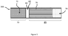
- FIG. 5 shows an aerosol-generating article 300 configured to generate an aerosol by heating rather than burning the aerosol-generating substrate.
- the aerosol-generating article 300 comprises a rod 70 at an upstream end.
- the rod 70 comprises an aerosol-generating substrate 72.
- the aerosol-generating article 300 also comprises a filter 80 at a downstream end.
- the filter 80 comprises an aerosol-cooling element 76 and a segment of filtration material 78 downstream of the aerosol-cooling element 76.
- the filter 80 and rod 70 are in axial alignment with one another and each of the components of the filter 70 are in axial alignment.
- the aerosol-generating article 300 also comprises a bridging element 82 comprising a single wrapper.
- the single wrapper comprises adhesive (not shown in Figure 5 ) to permanently secure the filter 80 to the rod 70.
- the bridging element 82 has a basis weight of 50 grams per square meter or higher.
- a cavity 84 is located between the rod 70 and the filter 80.
- the cavity 84 is delimited by the ends of the rod 70 and the filter 80 and by the inner surface of the single wrapper of the bridging element 80.
- the inner surface of the single wrapper extends circumferentially around the cavity 84, extending around the complete circumference of the cavity 84.
- the cavity 84 being partially delimited by the single wrapper of the bridging element 80 having a basis weight of 50 grams per square meter or greater provides strength to the aerosol-generating article in the region of the cavity and so prevents the cavity 84 from collapsing, particularly when the aerosol-generating article experiences longitudinal forces, for example, when being inserted into packaging or when being inserted into an aerosol-generating device.
Landscapes
- Engineering & Computer Science (AREA)
- Mechanical Engineering (AREA)
- Cigarettes, Filters, And Manufacturing Of Filters (AREA)
- Nozzles (AREA)
- Containers And Packaging Bodies Having A Special Means To Remove Contents (AREA)
- Catching Or Destruction (AREA)
- Agricultural Chemicals And Associated Chemicals (AREA)
- Medicinal Preparation (AREA)
Claims (15)
- Article de génération d'aérosol (10, 100, 200, 300) comprenant :une tige (20, 70) comprenant un substrat de génération d'aérosol (22, 72) ;un filtre (30, 80) en alignement axial avec la tige ;un élément de pontage (40, 50, 60, 82) comprenant une première enveloppe (42, 52, 62), la première enveloppe entourant la tige et le filtre et arrimant le filtre à la tige ; etune cavité (44, 84) située entre la tige et le filtre, la cavité étant partiellement délimitée par la surface intérieure de la première enveloppe dans une première portion (65) de l'élément de pontage,dans lequel la première portion de l'élément de pontage a un grammage de 50 grammes par mètre carré ou plus.
- Article de génération d'aérosol (10, 100, 200, 300) selon la revendication 1, dans lequel la cavité (44, 84) a une longueur d'au moins 2 millimètres.
- Article de génération d'aérosol (10, 100, 200, 300) selon la revendication 1 ou 2, dans lequel la première portion (65) de l'élément de pontage (40, 50, 60, 82) a un grammage de 70 grammes par mètre carré ou plus.
- Article de génération d'aérosol (10, 100, 200, 300) selon l'une quelconque des revendications précédentes, dans lequel la première portion (65) de l'élément de pontage (40, 50, 60, 82) a une épaisseur d'entre 50 micromètres et 140 micromètres.
- Article de génération d'aérosol (10, 100, 200, 300) selon l'une quelconque des revendications précédentes, dans lequel l'extrémité amont de la cavité (44, 84) est délimitée par la tige (20, 70) et l'extrémité aval de la cavité est délimitée par le filtre (30, 80).
- Article de génération d'aérosol (10, 100, 200, 300) selon l'une quelconque des revendications précédentes, dans lequel la première portion (65) de l'élément de pontage (40, 50, 60, 82) s'étend le long de la longueur de l'élément de pontage sur une distance d'au moins 1,2 fois la longueur de la cavité (44, 84).
- Article de génération d'aérosol (10, 100, 200, 300) selon l'une quelconque des revendications précédentes, dans lequel la première portion (65) de l'élément de pontage (40, 50, 60, 82) s'étend sur une distance d'entre 4 millimètres et 10 millimètres le long de la longueur de l'élément de pontage.
- Article de génération d'aérosol (10, 100, 200, 300) selon l'une quelconque des revendications précédentes, dans lequel le filtre (30, 80) est entouré par la première portion (65) de l'élément de pontage (40, 50, 60, 82).
- Article de génération d'aérosol (10, 100, 200, 300) selon l'une quelconque des revendications précédentes, dans lequel la tige (20, 70) est entourée par la première portion (65) de l'élément de pontage (40, 50, 60, 82).
- Article de génération d'aérosol (10, 300) selon l'une quelconque des revendications précédentes, dans lequel l'élément de pontage (40, 82) comprend une enveloppe (42) unique.
- Article de génération d'aérosol (100, 200) selon l'une quelconque des revendications 1 à 9, dans lequel l'élément de pontage (50, 60) comprend une deuxième enveloppe (53, 64) entourant la première enveloppe (52, 62).
- Article de génération d'aérosol (10, 100, 200, 300) selon l'une quelconque des revendications précédentes, dans lequel la surface intérieure de la première enveloppe (42, 52, 62) dans la première portion de l'élément de pontage (40, 50, 60, 82) s'étend circonférentiellement autour de la cavité (44, 84) sur une distance supérieure à 5 millimètres.
- Article de génération d'aérosol (10, 100, 200, 300) selon l'une quelconque des revendications précédentes, dans lequel la surface intérieure de la première enveloppe (42, 52, 62) dans la première portion de l'élément de pontage (40, 50, 60, 82) a une aire de surface supérieure à 25 millimètres carrés.
- Récipient comprenant une pluralité d'articles de génération d'aérosol (10, 100, 200, 300), dans lequel au moins 50 pour cent des articles de génération d'aérosol dans le récipient sont des articles de génération d'aérosol selon l'une quelconque des revendications 1 à 13.
- Procédé de fabrication d'un article de génération d'aérosol (10, 100, 200, 300) comprenant :la fourniture d'une tige (20, 70) comprenant un substrat de génération d'aérosol (22, 72) ;la fourniture d'un filtre (30, 80) ;la fourniture d'un élément de pontage (40, 50, 60, 82) comprenant une première enveloppe (42, 52, 62) ; etl'arrimage du filtre à la tige à l'aide de l'élément de pontage de sorte que la première enveloppe entoure la tige et le filtre selon une relation espacée pour former une cavité (44, 84) entre la tige et le filtre, la cavité étant partiellement délimitée par la surface intérieure de la première enveloppe dans une première portion de l'élément de pontage,dans lequel la première portion de l'élément de pontage a un grammage de 50 grammes par mètre carré ou plus.
Applications Claiming Priority (2)
| Application Number | Priority Date | Filing Date | Title |
|---|---|---|---|
| EP20158535 | 2020-02-20 | ||
| PCT/EP2021/054229 WO2021165509A1 (fr) | 2020-02-20 | 2021-02-19 | Article de génération d'aérosol doté d'un élément de liaison ayant un poids de base |
Publications (3)
| Publication Number | Publication Date |
|---|---|
| EP4106559A1 EP4106559A1 (fr) | 2022-12-28 |
| EP4106559B1 true EP4106559B1 (fr) | 2024-04-03 |
| EP4106559C0 EP4106559C0 (fr) | 2024-04-03 |
Family
ID=69713958
Family Applications (1)
| Application Number | Title | Priority Date | Filing Date |
|---|---|---|---|
| EP21705230.7A Active EP4106559B1 (fr) | 2020-02-20 | 2021-02-19 | Article de génération d'aérosol doté d'un élément de pontage à poids de base |
Country Status (18)
| Country | Link |
|---|---|
| US (1) | US20230084346A1 (fr) |
| EP (1) | EP4106559B1 (fr) |
| JP (2) | JP2023513963A (fr) |
| KR (1) | KR20220143697A (fr) |
| CN (1) | CN115135179A (fr) |
| AU (1) | AU2021225063A1 (fr) |
| BR (1) | BR112022016255A2 (fr) |
| CA (1) | CA3168160A1 (fr) |
| ES (1) | ES2978036T3 (fr) |
| HU (1) | HUE066419T2 (fr) |
| IL (1) | IL295665B2 (fr) |
| MX (1) | MX2022009960A (fr) |
| MY (1) | MY209176A (fr) |
| PH (1) | PH12022552039A1 (fr) |
| PL (1) | PL4106559T3 (fr) |
| UA (1) | UA130676C2 (fr) |
| WO (1) | WO2021165509A1 (fr) |
| ZA (1) | ZA202210153B (fr) |
Families Citing this family (3)
| Publication number | Priority date | Publication date | Assignee | Title |
|---|---|---|---|---|
| EP4436410A1 (fr) * | 2021-11-22 | 2024-10-02 | Philip Morris Products S.A. | Article de génération d'aérosol comprenant un papier d'emballage avec des sections faisant saillie dans la direction amont |
| CN114431525B (zh) * | 2022-03-08 | 2024-06-25 | 东莞市本草香弹科技有限公司 | 一种滤嘴装置其用途与使用方法、及气溶胶产生系统 |
| KR20250002407A (ko) | 2022-05-11 | 2025-01-07 | 필립모리스 프로덕츠 에스.에이. | 스페이서를 갖는 컨베이어 상의 에어로졸 발생 물품 조립체 |
Citations (20)
| Publication number | Priority date | Publication date | Assignee | Title |
|---|---|---|---|---|
| US5439011A (en) | 1993-06-24 | 1995-08-08 | B.A.T. Cigarettenfabriken Gmbh | Coaxial filter cigarette |
| WO1996032854A2 (fr) | 1995-04-20 | 1996-10-24 | Philip Morris Products Inc. | Cigarette et dispositif chauffant destines a un systeme electrique servant a fumer |
| EP0791688A1 (fr) | 1995-09-07 | 1997-08-27 | Japan Tobacco Inc. | Papier a cigarette pour produits a base de tabac |
| WO2000000047A1 (fr) | 1998-06-30 | 2000-01-06 | Philip Morris Products, Inc. | Cigarette et filtre presentant un niveau eleve de ventilation |
| US20070240729A1 (en) | 2003-01-30 | 2007-10-18 | Philip Morris Usa Inc. | Opposed seam electrically heated cigarette smoking system |
| WO2009106374A1 (fr) | 2008-02-27 | 2009-09-03 | British American Tobacco (Investments) Limited | Filtre pour article à fumer |
| WO2013057282A1 (fr) | 2011-10-21 | 2013-04-25 | Philip Morris Products S.A. | Article à fumer doté d'une cavité d'embouchure comportant des éléments d'impression |
| US20130104915A1 (en) | 2010-04-01 | 2013-05-02 | Delfortgroup Ag | Perforated Cigarette Paper |
| WO2013076098A2 (fr) | 2011-11-21 | 2013-05-30 | Philip Morris Products S.A. | Extracteur pour un dispositif de génération d'aérosol |
| US20130199551A1 (en) | 2010-03-29 | 2013-08-08 | British American Tobacco (Investments) Limited | Smoking Article and Method of Manufacturing a Smoking Article |
| EP2783590A1 (fr) | 2011-12-21 | 2014-10-01 | Japan Tobacco, Inc. | Tube en papier et outil d'aspiration de saveur utilisant ce tube |
| WO2014158051A1 (fr) | 2013-03-28 | 2014-10-02 | Philip Morris Products S.A. | Article à fumer ayant un filtre à cavités multiples |
| WO2015124242A1 (fr) | 2014-02-24 | 2015-08-27 | Philip Morris Products S.A. | Filtre amélioré en termes de dureté et d'efficacité de filtration |
| WO2017198837A1 (fr) | 2016-05-20 | 2017-11-23 | British American Tobacco (Investments) Limited | Article destiné à être utilisé dans un appareil permettant de chauffer un matériau à fumer |
| WO2017198876A1 (fr) | 2016-05-20 | 2017-11-23 | British American Tobacco (Investments) Limited | Filtre pour dispositif générateur d'aérosol |
| CN107981411A (zh) | 2017-12-28 | 2018-05-04 | 浙江中烟工业有限责任公司 | 一种加热不燃烧卷烟烟支 |
| US20190059449A1 (en) | 2016-04-27 | 2019-02-28 | Japan Tobacco Inc. | Flavor inhaler |
| EP3449739A1 (fr) | 2016-04-28 | 2019-03-06 | Japan Tobacco, Inc. | Cigarette à filtre |
| CN109512022A (zh) | 2018-12-06 | 2019-03-26 | 陈征 | 带封口膜的空管填充式加热不燃烧发烟制品的制备方法及应用 |
| EP3566591A1 (fr) | 2018-05-12 | 2019-11-13 | Shenzhen Dakavape Tech Co., Ltd. | Produit pour la cuisson et l'atomisation |
Family Cites Families (20)
| Publication number | Priority date | Publication date | Assignee | Title |
|---|---|---|---|---|
| JP3108906U (ja) * | 2004-11-22 | 2005-04-28 | 和彦 川本 | ライタ入りシガレットケース |
| BRPI0603954B1 (pt) * | 2006-09-25 | 2014-05-20 | Souza Cruz Sa | Artigo para fumar e método de fabricação de um artigo para fumar |
| US20100108081A1 (en) * | 2008-10-31 | 2010-05-06 | Leigh Ann Blevins Joyce | Filtered cigarette with flavored tipping material |
| EP2253233A1 (fr) * | 2009-05-21 | 2010-11-24 | Philip Morris Products S.A. | Système de fumage chauffé électriquement |
| JP2015033330A (ja) * | 2011-11-30 | 2015-02-19 | 日本たばこ産業株式会社 | 喫煙物品用フィルターおよび喫煙物品 |
| WO2013179428A1 (fr) * | 2012-05-30 | 2013-12-05 | 日本たばこ産業株式会社 | Cigarette et éléments d'emballage |
| US20150157052A1 (en) * | 2013-12-05 | 2015-06-11 | R. J. Reynolds Tobacco Company | Smoking article and associated manufacturing method |
| JP2017135984A (ja) * | 2014-06-10 | 2017-08-10 | 日本たばこ産業株式会社 | たばこ製品用のフィルタ及びたばこ製品 |
| JP6770512B2 (ja) * | 2014-09-30 | 2020-10-14 | フィリップ・モーリス・プロダクツ・ソシエテ・アノニム | オーバーチッピングバンドを備えた喫煙物品 |
| JP6701187B2 (ja) * | 2014-10-20 | 2020-05-27 | フィリップ・モーリス・プロダクツ・ソシエテ・アノニム | 疎水性チッピングペーパー |
| TW201635927A (zh) * | 2015-03-27 | 2016-10-16 | 菲利浦莫里斯製品股份有限公司 | 具有嘴端空腔及通氣的吸煙物件 |
| CN104921296A (zh) * | 2015-06-25 | 2015-09-23 | 云南中烟工业有限责任公司 | 一种用于加热不燃烧型卷烟的复合嘴棒 |
| BR112018003916A2 (pt) * | 2015-08-28 | 2018-09-25 | Jt International S.A. | ?artigo de fumo? |
| US10897928B2 (en) * | 2016-06-29 | 2021-01-26 | Essentra Filter Products Development Co Pte. Ltd. | Shaped elements for smoking devices |
| MX2019003424A (es) * | 2016-09-29 | 2019-07-18 | Philip Morris Products Sa | Articulo generador de aerosol con envoltura de boquilla modificada con porcion de envoltura de boquilla removible. |
| CN109996456B (zh) * | 2016-12-21 | 2021-12-03 | 菲利普莫里斯生产公司 | 具有熄灭装置的吸烟制品 |
| AU2018377970B2 (en) * | 2017-11-30 | 2024-03-07 | Philip Morris Products S.A. | Aerosol-generating article having mouthpiece with upstream cavity |
| KR20200094772A (ko) * | 2017-12-22 | 2020-08-07 | 니뽄 다바코 산교 가부시키가이샤 | 흡연 물품 및 흡연 물품의 필터 |
| TWM557523U (zh) * | 2017-12-22 | 2018-04-01 | Xie ming long | 香菸結構改良 |
| GB2574790A (en) * | 2018-04-24 | 2019-12-25 | British American Tobacco Investments Ltd | A tobacco industry product component and a method of manufacturing a tobacco industry product component |
-
2021
- 2021-02-19 PH PH1/2022/552039A patent/PH12022552039A1/en unknown
- 2021-02-19 JP JP2022549928A patent/JP2023513963A/ja active Pending
- 2021-02-19 CA CA3168160A patent/CA3168160A1/fr active Pending
- 2021-02-19 WO PCT/EP2021/054229 patent/WO2021165509A1/fr not_active Ceased
- 2021-02-19 MY MYPI2022004362A patent/MY209176A/en unknown
- 2021-02-19 AU AU2021225063A patent/AU2021225063A1/en active Pending
- 2021-02-19 US US17/801,050 patent/US20230084346A1/en active Pending
- 2021-02-19 HU HUE21705230A patent/HUE066419T2/hu unknown
- 2021-02-19 EP EP21705230.7A patent/EP4106559B1/fr active Active
- 2021-02-19 MX MX2022009960A patent/MX2022009960A/es unknown
- 2021-02-19 UA UAA202203464A patent/UA130676C2/uk unknown
- 2021-02-19 ES ES21705230T patent/ES2978036T3/es active Active
- 2021-02-19 BR BR112022016255A patent/BR112022016255A2/pt unknown
- 2021-02-19 KR KR1020227031518A patent/KR20220143697A/ko active Pending
- 2021-02-19 IL IL295665A patent/IL295665B2/en unknown
- 2021-02-19 PL PL21705230.7T patent/PL4106559T3/pl unknown
- 2021-02-19 CN CN202180015573.XA patent/CN115135179A/zh active Pending
-
2022
- 2022-09-13 ZA ZA2022/10153A patent/ZA202210153B/en unknown
-
2026
- 2026-01-05 JP JP2026000463A patent/JP2026040799A/ja active Pending
Patent Citations (20)
| Publication number | Priority date | Publication date | Assignee | Title |
|---|---|---|---|---|
| US5439011A (en) | 1993-06-24 | 1995-08-08 | B.A.T. Cigarettenfabriken Gmbh | Coaxial filter cigarette |
| WO1996032854A2 (fr) | 1995-04-20 | 1996-10-24 | Philip Morris Products Inc. | Cigarette et dispositif chauffant destines a un systeme electrique servant a fumer |
| EP0791688A1 (fr) | 1995-09-07 | 1997-08-27 | Japan Tobacco Inc. | Papier a cigarette pour produits a base de tabac |
| WO2000000047A1 (fr) | 1998-06-30 | 2000-01-06 | Philip Morris Products, Inc. | Cigarette et filtre presentant un niveau eleve de ventilation |
| US20070240729A1 (en) | 2003-01-30 | 2007-10-18 | Philip Morris Usa Inc. | Opposed seam electrically heated cigarette smoking system |
| WO2009106374A1 (fr) | 2008-02-27 | 2009-09-03 | British American Tobacco (Investments) Limited | Filtre pour article à fumer |
| US20130199551A1 (en) | 2010-03-29 | 2013-08-08 | British American Tobacco (Investments) Limited | Smoking Article and Method of Manufacturing a Smoking Article |
| US20130104915A1 (en) | 2010-04-01 | 2013-05-02 | Delfortgroup Ag | Perforated Cigarette Paper |
| WO2013057282A1 (fr) | 2011-10-21 | 2013-04-25 | Philip Morris Products S.A. | Article à fumer doté d'une cavité d'embouchure comportant des éléments d'impression |
| WO2013076098A2 (fr) | 2011-11-21 | 2013-05-30 | Philip Morris Products S.A. | Extracteur pour un dispositif de génération d'aérosol |
| EP2783590A1 (fr) | 2011-12-21 | 2014-10-01 | Japan Tobacco, Inc. | Tube en papier et outil d'aspiration de saveur utilisant ce tube |
| WO2014158051A1 (fr) | 2013-03-28 | 2014-10-02 | Philip Morris Products S.A. | Article à fumer ayant un filtre à cavités multiples |
| WO2015124242A1 (fr) | 2014-02-24 | 2015-08-27 | Philip Morris Products S.A. | Filtre amélioré en termes de dureté et d'efficacité de filtration |
| US20190059449A1 (en) | 2016-04-27 | 2019-02-28 | Japan Tobacco Inc. | Flavor inhaler |
| EP3449739A1 (fr) | 2016-04-28 | 2019-03-06 | Japan Tobacco, Inc. | Cigarette à filtre |
| WO2017198837A1 (fr) | 2016-05-20 | 2017-11-23 | British American Tobacco (Investments) Limited | Article destiné à être utilisé dans un appareil permettant de chauffer un matériau à fumer |
| WO2017198876A1 (fr) | 2016-05-20 | 2017-11-23 | British American Tobacco (Investments) Limited | Filtre pour dispositif générateur d'aérosol |
| CN107981411A (zh) | 2017-12-28 | 2018-05-04 | 浙江中烟工业有限责任公司 | 一种加热不燃烧卷烟烟支 |
| EP3566591A1 (fr) | 2018-05-12 | 2019-11-13 | Shenzhen Dakavape Tech Co., Ltd. | Produit pour la cuisson et l'atomisation |
| CN109512022A (zh) | 2018-12-06 | 2019-03-26 | 陈征 | 带封口膜的空管填充式加热不燃烧发烟制品的制备方法及应用 |
Non-Patent Citations (2)
| Title |
|---|
| APPLICATION AS FILED |
| LOKOVIC MARK: "Understanding Paper Weights and Thickness", 31 May 2020 (2020-05-31), XP055912245, Retrieved from the Internet <URL:http://training.kellypaper.com/wp-content/uploads/2020/05/Understanding-Basis-Weights-Thickness.pdf> [retrieved on 20220412] |
Also Published As
| Publication number | Publication date |
|---|---|
| JP2023513963A (ja) | 2023-04-04 |
| KR20220143697A (ko) | 2022-10-25 |
| AU2021225063A1 (en) | 2022-09-08 |
| CN115135179A (zh) | 2022-09-30 |
| US20230084346A1 (en) | 2023-03-16 |
| MX2022009960A (es) | 2022-09-19 |
| UA130676C2 (uk) | 2026-04-15 |
| ZA202210153B (en) | 2023-12-20 |
| IL295665A (en) | 2022-10-01 |
| PL4106559T3 (pl) | 2024-08-26 |
| EP4106559A1 (fr) | 2022-12-28 |
| MY209176A (en) | 2025-06-26 |
| WO2021165509A1 (fr) | 2021-08-26 |
| BR112022016255A2 (pt) | 2022-10-11 |
| IL295665B2 (en) | 2026-04-01 |
| IL295665B1 (en) | 2025-12-01 |
| EP4106559C0 (fr) | 2024-04-03 |
| CA3168160A1 (fr) | 2021-08-26 |
| ES2978036T3 (es) | 2024-09-04 |
| JP2026040799A (ja) | 2026-03-09 |
| HUE066419T2 (hu) | 2024-08-28 |
| PH12022552039A1 (en) | 2023-11-20 |
Similar Documents
| Publication | Publication Date | Title |
|---|---|---|
| CN111093402B (zh) | 用于气溶胶生成制品的支承元件 | |
| AU2020235462B2 (en) | Aerosol generation | |
| EP3813572B1 (fr) | Article générateur d'aérosol et appareil pour former un article générateur d'aérosol | |
| TWI586285B (zh) | 具有生物可降解風味產生成分之氣溶膠產生物品 | |
| KR102697052B1 (ko) | 에어로졸 발생 물품 및 에어로졸 발생 물품 내 세그먼트로서 사용하기 위한 저 저항 지지 요소 | |
| EP3713430B1 (fr) | Article pour fumeurs | |
| JP7493600B2 (ja) | 非燃焼系エアロゾル供給システムに使用するための物品 | |
| EP4106559B1 (fr) | Article de génération d'aérosol doté d'un élément de pontage à poids de base | |
| EP4262450B1 (fr) | Élément tubulaire creux pour un article de génération d'aérosol | |
| JP7795567B2 (ja) | 喫煙品 | |
| JP2025501156A (ja) | 送達システムのための構成要素、ならびに送達システムのための構成要素を製造するための方法および装置 | |
| HK40083340A (en) | Aerosol-generating article having bridging element with basis weight | |
| HK40083340B (en) | Aerosol-generating article having bridging element with basis weight | |
| RU2830560C1 (ru) | Изделие, генерирующее аэрозоль, контейнер для изделий, генерирующих аэрозоль, и способ изготовления изделия, генерирующего аэрозоль | |
| EP4106558B1 (fr) | Article de génération d'aérosol ayant un élément de pontage comportant un facteur de réflectance | |
| HK1200287B (en) | Aerosol-generating article having a flavour-generating component |
Legal Events
| Date | Code | Title | Description |
|---|---|---|---|
| STAA | Information on the status of an ep patent application or granted ep patent |
Free format text: STATUS: UNKNOWN |
|
| STAA | Information on the status of an ep patent application or granted ep patent |
Free format text: STATUS: THE INTERNATIONAL PUBLICATION HAS BEEN MADE |
|
| PUAI | Public reference made under article 153(3) epc to a published international application that has entered the european phase |
Free format text: ORIGINAL CODE: 0009012 |
|
| STAA | Information on the status of an ep patent application or granted ep patent |
Free format text: STATUS: REQUEST FOR EXAMINATION WAS MADE |
|
| 17P | Request for examination filed |
Effective date: 20220819 |
|
| AK | Designated contracting states |
Kind code of ref document: A1 Designated state(s): AL AT BE BG CH CY CZ DE DK EE ES FI FR GB GR HR HU IE IS IT LI LT LU LV MC MK MT NL NO PL PT RO RS SE SI SK SM TR |
|
| DAV | Request for validation of the european patent (deleted) | ||
| DAX | Request for extension of the european patent (deleted) | ||
| REG | Reference to a national code |
Ref country code: HK Ref legal event code: DE Ref document number: 40083340 Country of ref document: HK |
|
| GRAP | Despatch of communication of intention to grant a patent |
Free format text: ORIGINAL CODE: EPIDOSNIGR1 |
|
| STAA | Information on the status of an ep patent application or granted ep patent |
Free format text: STATUS: GRANT OF PATENT IS INTENDED |
|
| INTG | Intention to grant announced |
Effective date: 20231025 |
|
| GRAS | Grant fee paid |
Free format text: ORIGINAL CODE: EPIDOSNIGR3 |
|
| GRAA | (expected) grant |
Free format text: ORIGINAL CODE: 0009210 |
|
| STAA | Information on the status of an ep patent application or granted ep patent |
Free format text: STATUS: THE PATENT HAS BEEN GRANTED |
|
| AK | Designated contracting states |
Kind code of ref document: B1 Designated state(s): AL AT BE BG CH CY CZ DE DK EE ES FI FR GB GR HR HU IE IS IT LI LT LU LV MC MK MT NL NO PL PT RO RS SE SI SK SM TR |
|
| REG | Reference to a national code |
Ref country code: CH Ref legal event code: EP |
|
| REG | Reference to a national code |
Ref country code: IE Ref legal event code: FG4D |
|
| REG | Reference to a national code |
Ref country code: DE Ref legal event code: R096 Ref document number: 602021011278 Country of ref document: DE |
|
| U01 | Request for unitary effect filed |
Effective date: 20240403 |
|
| U07 | Unitary effect registered |
Designated state(s): AT BE BG DE DK EE FI FR IT LT LU LV MT NL PT SE SI Effective date: 20240408 |
|
| REG | Reference to a national code |
Ref country code: SK Ref legal event code: T3 Ref document number: E 44028 Country of ref document: SK |
|
| REG | Reference to a national code |
Ref country code: GR Ref legal event code: EP Ref document number: 20240401304 Country of ref document: GR Effective date: 20240716 |
|
| REG | Reference to a national code |
Ref country code: HU Ref legal event code: AG4A Ref document number: E066419 Country of ref document: HU |
|
| U1N | Appointed representative for the unitary patent procedure changed after the registration of the unitary effect |
Representative=s name: REDDIE & GROSE LLP; GB |
|
| REG | Reference to a national code |
Ref country code: ES Ref legal event code: FG2A Ref document number: 2978036 Country of ref document: ES Kind code of ref document: T3 Effective date: 20240904 |
|
| PG25 | Lapsed in a contracting state [announced via postgrant information from national office to epo] |
Ref country code: IS Free format text: LAPSE BECAUSE OF FAILURE TO SUBMIT A TRANSLATION OF THE DESCRIPTION OR TO PAY THE FEE WITHIN THE PRESCRIBED TIME-LIMIT Effective date: 20240803 |
|
| PG25 | Lapsed in a contracting state [announced via postgrant information from national office to epo] |
Ref country code: HR Free format text: LAPSE BECAUSE OF FAILURE TO SUBMIT A TRANSLATION OF THE DESCRIPTION OR TO PAY THE FEE WITHIN THE PRESCRIBED TIME-LIMIT Effective date: 20240403 |
|
| PG25 | Lapsed in a contracting state [announced via postgrant information from national office to epo] |
Ref country code: NO Free format text: LAPSE BECAUSE OF FAILURE TO SUBMIT A TRANSLATION OF THE DESCRIPTION OR TO PAY THE FEE WITHIN THE PRESCRIBED TIME-LIMIT Effective date: 20240703 Ref country code: IS Free format text: LAPSE BECAUSE OF FAILURE TO SUBMIT A TRANSLATION OF THE DESCRIPTION OR TO PAY THE FEE WITHIN THE PRESCRIBED TIME-LIMIT Effective date: 20240803 Ref country code: HR Free format text: LAPSE BECAUSE OF FAILURE TO SUBMIT A TRANSLATION OF THE DESCRIPTION OR TO PAY THE FEE WITHIN THE PRESCRIBED TIME-LIMIT Effective date: 20240403 Ref country code: RS Free format text: LAPSE BECAUSE OF FAILURE TO SUBMIT A TRANSLATION OF THE DESCRIPTION OR TO PAY THE FEE WITHIN THE PRESCRIBED TIME-LIMIT Effective date: 20240703 |
|
| REG | Reference to a national code |
Ref country code: DE Ref legal event code: R026 Ref document number: 602021011278 Country of ref document: DE |
|
| PLBI | Opposition filed |
Free format text: ORIGINAL CODE: 0009260 |
|
| PLAX | Notice of opposition and request to file observation + time limit sent |
Free format text: ORIGINAL CODE: EPIDOSNOBS2 |
|
| PG25 | Lapsed in a contracting state [announced via postgrant information from national office to epo] |
Ref country code: SM Free format text: LAPSE BECAUSE OF FAILURE TO SUBMIT A TRANSLATION OF THE DESCRIPTION OR TO PAY THE FEE WITHIN THE PRESCRIBED TIME-LIMIT Effective date: 20240403 |
|
| PG25 | Lapsed in a contracting state [announced via postgrant information from national office to epo] |
Ref country code: SM Free format text: LAPSE BECAUSE OF FAILURE TO SUBMIT A TRANSLATION OF THE DESCRIPTION OR TO PAY THE FEE WITHIN THE PRESCRIBED TIME-LIMIT Effective date: 20240403 |
|
| 26 | Opposition filed |
Opponent name: IMPERIAL TOBACCO LIMITED Effective date: 20250102 |
|
| U1N | Appointed representative for the unitary patent procedure changed after the registration of the unitary effect |
Representative=s name: CHUNG, HSU MIN; GB |
|
| U1N | Appointed representative for the unitary patent procedure changed after the registration of the unitary effect |
Representative=s name: HGF; GB |
|
| U20 | Renewal fee for the european patent with unitary effect paid |
Year of fee payment: 5 Effective date: 20250221 |
|
| PLBB | Reply of patent proprietor to notice(s) of opposition received |
Free format text: ORIGINAL CODE: EPIDOSNOBS3 |
|
| PGFP | Annual fee paid to national office [announced via postgrant information from national office to epo] |
Ref country code: ES Payment date: 20250331 Year of fee payment: 5 |
|
| PG25 | Lapsed in a contracting state [announced via postgrant information from national office to epo] |
Ref country code: MC Free format text: LAPSE BECAUSE OF FAILURE TO SUBMIT A TRANSLATION OF THE DESCRIPTION OR TO PAY THE FEE WITHIN THE PRESCRIBED TIME-LIMIT Effective date: 20240403 |
|
| PG25 | Lapsed in a contracting state [announced via postgrant information from national office to epo] |
Ref country code: IE Free format text: LAPSE BECAUSE OF NON-PAYMENT OF DUE FEES Effective date: 20250219 |
|
| REG | Reference to a national code |
Ref country code: CH Ref legal event code: U11 Free format text: ST27 STATUS EVENT CODE: U-0-0-U10-U11 (AS PROVIDED BY THE NATIONAL OFFICE) Effective date: 20260301 |
|
| PGFP | Annual fee paid to national office [announced via postgrant information from national office to epo] |
Ref country code: HU Payment date: 20260220 Year of fee payment: 6 |
|
| U20 | Renewal fee for the european patent with unitary effect paid |
Year of fee payment: 6 Effective date: 20260225 |
|
| PGFP | Annual fee paid to national office [announced via postgrant information from national office to epo] |
Ref country code: GB Payment date: 20260220 Year of fee payment: 6 |
|
| PGFP | Annual fee paid to national office [announced via postgrant information from national office to epo] |
Ref country code: RO Payment date: 20260209 Year of fee payment: 6 |
|
| PGFP | Annual fee paid to national office [announced via postgrant information from national office to epo] |
Ref country code: TR Payment date: 20260211 Year of fee payment: 6 |
|
| PGFP | Annual fee paid to national office [announced via postgrant information from national office to epo] |
Ref country code: CZ Payment date: 20260212 Year of fee payment: 6 Ref country code: CH Payment date: 20260301 Year of fee payment: 6 |
|
| PGFP | Annual fee paid to national office [announced via postgrant information from national office to epo] |
Ref country code: GR Payment date: 20260218 Year of fee payment: 6 Ref country code: PL Payment date: 20260216 Year of fee payment: 6 |
|
| PGFP | Annual fee paid to national office [announced via postgrant information from national office to epo] |
Ref country code: SK Payment date: 20260210 Year of fee payment: 6 |