EP4106665B1 - Dispositif de commande et de fonctionnement endodontique - Google Patents
Dispositif de commande et de fonctionnement endodontique Download PDFInfo
- Publication number
- EP4106665B1 EP4106665B1 EP21820617.5A EP21820617A EP4106665B1 EP 4106665 B1 EP4106665 B1 EP 4106665B1 EP 21820617 A EP21820617 A EP 21820617A EP 4106665 B1 EP4106665 B1 EP 4106665B1
- Authority
- EP
- European Patent Office
- Prior art keywords
- drive shaft
- surrounding
- cylindrical element
- coil
- central processing
- Prior art date
- Legal status (The legal status is an assumption and is not a legal conclusion. Google has not performed a legal analysis and makes no representation as to the accuracy of the status listed.)
- Active
Links
Images




Classifications
-
- A—HUMAN NECESSITIES
- A61—MEDICAL OR VETERINARY SCIENCE; HYGIENE
- A61C—DENTISTRY; APPARATUS OR METHODS FOR ORAL OR DENTAL HYGIENE
- A61C5/00—Filling or capping teeth
- A61C5/40—Implements for surgical treatment of the roots or nerves of the teeth; Nerve needles; Methods or instruments for medication of the roots
-
- A—HUMAN NECESSITIES
- A61—MEDICAL OR VETERINARY SCIENCE; HYGIENE
- A61C—DENTISTRY; APPARATUS OR METHODS FOR ORAL OR DENTAL HYGIENE
- A61C1/00—Dental machines for boring or cutting ; General features of dental machines or apparatus, e.g. hand-piece design
- A61C1/08—Machine parts specially adapted for dentistry
-
- A—HUMAN NECESSITIES
- A61—MEDICAL OR VETERINARY SCIENCE; HYGIENE
- A61C—DENTISTRY; APPARATUS OR METHODS FOR ORAL OR DENTAL HYGIENE
- A61C1/00—Dental machines for boring or cutting ; General features of dental machines or apparatus, e.g. hand-piece design
- A61C1/0007—Control devices or systems
-
- A—HUMAN NECESSITIES
- A61—MEDICAL OR VETERINARY SCIENCE; HYGIENE
- A61C—DENTISTRY; APPARATUS OR METHODS FOR ORAL OR DENTAL HYGIENE
- A61C1/00—Dental machines for boring or cutting ; General features of dental machines or apparatus, e.g. hand-piece design
- A61C1/0007—Control devices or systems
- A61C1/0015—Electrical systems
- A61C1/003—Control of rotation of instrument
-
- A—HUMAN NECESSITIES
- A61—MEDICAL OR VETERINARY SCIENCE; HYGIENE
- A61C—DENTISTRY; APPARATUS OR METHODS FOR ORAL OR DENTAL HYGIENE
- A61C1/00—Dental machines for boring or cutting ; General features of dental machines or apparatus, e.g. hand-piece design
- A61C1/0061—Air and water supply systems; Valves specially adapted therefor
-
- A—HUMAN NECESSITIES
- A61—MEDICAL OR VETERINARY SCIENCE; HYGIENE
- A61C—DENTISTRY; APPARATUS OR METHODS FOR ORAL OR DENTAL HYGIENE
- A61C1/00—Dental machines for boring or cutting ; General features of dental machines or apparatus, e.g. hand-piece design
- A61C1/02—Dental machines for boring or cutting ; General features of dental machines or apparatus, e.g. hand-piece design characterised by the drive of the dental tools
-
- A—HUMAN NECESSITIES
- A61—MEDICAL OR VETERINARY SCIENCE; HYGIENE
- A61C—DENTISTRY; APPARATUS OR METHODS FOR ORAL OR DENTAL HYGIENE
- A61C1/00—Dental machines for boring or cutting ; General features of dental machines or apparatus, e.g. hand-piece design
- A61C1/02—Dental machines for boring or cutting ; General features of dental machines or apparatus, e.g. hand-piece design characterised by the drive of the dental tools
- A61C1/06—Dental machines for boring or cutting ; General features of dental machines or apparatus, e.g. hand-piece design characterised by the drive of the dental tools with electric drive
-
- A—HUMAN NECESSITIES
- A61—MEDICAL OR VETERINARY SCIENCE; HYGIENE
- A61C—DENTISTRY; APPARATUS OR METHODS FOR ORAL OR DENTAL HYGIENE
- A61C1/00—Dental machines for boring or cutting ; General features of dental machines or apparatus, e.g. hand-piece design
- A61C1/08—Machine parts specially adapted for dentistry
- A61C1/14—Tool-holders, i.e. operating tool holders, e.g. burr holders
-
- A—HUMAN NECESSITIES
- A61—MEDICAL OR VETERINARY SCIENCE; HYGIENE
- A61C—DENTISTRY; APPARATUS OR METHODS FOR ORAL OR DENTAL HYGIENE
- A61C1/00—Dental machines for boring or cutting ; General features of dental machines or apparatus, e.g. hand-piece design
- A61C1/08—Machine parts specially adapted for dentistry
- A61C1/14—Tool-holders, i.e. operating tool holders, e.g. burr holders
- A61C1/141—Tool-holders, i.e. operating tool holders, e.g. burr holders in an angled handpiece
-
- A—HUMAN NECESSITIES
- A61—MEDICAL OR VETERINARY SCIENCE; HYGIENE
- A61C—DENTISTRY; APPARATUS OR METHODS FOR ORAL OR DENTAL HYGIENE
- A61C1/00—Dental machines for boring or cutting ; General features of dental machines or apparatus, e.g. hand-piece design
- A61C1/08—Machine parts specially adapted for dentistry
- A61C1/18—Flexible shafts; Clutches or the like; Bearings or lubricating arrangements; Drives or transmissions
- A61C1/181—Bearings or lubricating arrangements, e.g. air-cushion bearings
-
- A—HUMAN NECESSITIES
- A61—MEDICAL OR VETERINARY SCIENCE; HYGIENE
- A61C—DENTISTRY; APPARATUS OR METHODS FOR ORAL OR DENTAL HYGIENE
- A61C2204/00—Features not otherwise provided for
- A61C2204/002—Features not otherwise provided for using batteries
Definitions
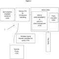
- the present invention relates to a device for driving an endodontic file head of an endodontic device and operating a remote pump.
- an irrigation solution such as sodium hypochlorite solution
- sodium hypochlorite solution is used in order to clean the root canal and the root canal is thereby shaped by rotational motion of a file.
- the European patent application EP 2 449 999 A1 relates to a dental fluid-driven handle with a control circuit for the control of the rotational speed of a rotary part to a predetermined rotational speed.
- the handle comprises a rotary part that can be set in rotary motion by a drive fluid, a fluid line carrying the drive fluid to or from the rotary part, and a control circuit that is designed to control the rotational speed of the rotary part.
- US 2007/25461 A1 relates to a wireless remote control for dental equipment, such as dental scaler tools, dental drills, prophy angles and other rotary instruments.
- US 2019/282332 A1 describes an endodontic treatment method without a file in order to avoid spreading of a smear layer, which may include organic and/or inorganic debris, on the root canal wall after instrumentation and to avoid wounding of the root canal wall or apex.
- WO 2012/054905 A2 discloses an endodontic device comprising a fluid retainer to be applied to the tooth to retain fluid in a chamber of the tooth; and a pressure wave generator having a distal portion, the distal portion being configured to be inserted through the fluid retainer into the tooth chamber.
- endodontic file head refers to the part of the dental device containing at least an endodontic instrument and a drive arrangement or part of a drive arrangement. Moreover, the dental device may also contain an endodontic instrument holder.
- motorized power handle refers to a handle, to be held by the user while operating the dental tool from which motive power is supplied to move the endodontic instrument.
- remote pump refers to a pump which is remote of the endodontic device (1).
- the signal communication between the endodontic device (1) and the remote pump is performed wireless.
- the gear (110) is designed as a bevel gear, and more preferably it is a steel bevel gear.
- An embodiment according to the invention is related to a device (10), wherein the gear (110) is a steel bevel gear (115).
- an embodiment according to the invention is directed to a device (10) for driving an endodontic file head (500) of an endodontic device (1) and operating a remote pump, the device comprising:
- the gear can be made of any material.
- the gear is made of iron or iron alloy.
- the iron alloy contains martensite as a grain structure. It is preferred if the gear is made of a ferromagnetic material.
- the gear (110) is preferably made of an AISI/SAE 440C annealed QQ-S-763 Class 440C condition A.
- the drive shaft (120) can be composed of any material.
- the material is preferably not ferromagnetic.
- the drive shaft (120) is composed of iron or iron alloy, more preferably iron alloy.
- the iron alloy can be steel, and more preferably stainless steel. It is preferred if the iron or iron alloy is not ferromagnetic.
- the steel is thus preferably an austenite, and more preferably stainless steel austenite.
- the steel can be a chromium-nickel steel, preferably AISI 316 (SAE 316). Still more preferably, the steel is AISI 316.
- the drive shaft (120) is made of an AISI 316 annealed stainless steel bar.
- the drive shaft (120) can contain at least one bearing (130) for the improvement of the rotational motion.
- the bearing (130) can be composed of any material.
- the bearing (130) is composed of iron or iron alloy, more preferably iron alloy.
- the iron alloy can be steel, and more preferably stainless steel. It is preferred if the iron or iron alloy is not ferromagnetic.
- the steel is thus preferably an austenite, and more preferably austenitic stainless steel.
- the steel can be a chromium-nickel steel, preferably AISI 316 (SAE 316). Still more preferably, the steel is AISI 316.
- the bearing (130) is made of an AISI 316 annealed stainless steel bar.
- the at least one bearing (130) is preferably positioned between the gear (110) and the magnet holding means (200).
- the bearings are preferably spatial separated by a bearing spacer (140).
- the device (10) according to the invention contains two bearings (130), wherein the two bearings (130) are positioned between the gear (110) and the magnet holding means (200), and wherein the two bearings (130) are spatially separated by a bearing spacer (140).
- the bearing spacer (140) can be made of any material.
- the bearing spacer is made of a polymer.
- the polymer is resistant of aqueous acids, aqueous bases and/or alcohols. More preferably, the polymer is resistant to aqueous acids namely hydrochloric acid and phosphoric acids.
- the polymer can be a thermosetting polymer (thermoset) or thermosoftening plastic (thermoplastic).
- the polymer is an organic polymer.
- the polymer can be selected from the group comprising or consisting of acrylonitrile butadiene styrene copolymer (ABS), acrylonitrile styrene (ANS), cellulose acetate, cellulose acetate butyrate, cellulose acetate propionate, cellulose acetate phthalate, cellulose nitrate, cyclic olefin copolymer, poly(ethene-co-tetrafluoroethene), poly(ethene-co-chlorortrifluoroethene), fluorinated ethylene propylene, polystyrene, high impact polystyrene, polybutylene adipate terephthalate, polybutylene succinate, polybutylene terephthalate, polycarbonate, polychlorotrifluoroethylene, polyethylene terephthalate, polylactide, polyethylene naphthalate, polyetherimide, polyetherketones (PEK) such as
- the polymer is selected from the group comprising or consisting of acrylonitrile butadiene styrene copolymer (ABS), acrylonitrile styrene (ANS), cellulose acetate, cellulose acetate butyrate, cellulose acetate propionate, cellulose acetate phthalate, cellulose nitrate, cyclic olefin copolymer, poly(ethene-co-tetrafluoroethene), poly(ethene-co-chlorortrifluoroethene), fluorinated ethylene propylene, polystyrene, high impact polystyrene, polybutylene adipate terephthalate, polybutylene succinate, polybutylene terephthalate, polycarbonate, polychlorotrifluoroethylene, polyethylene terephthalate, polylactide, polyethylene naphthalate, polyetherimide, polyetherketones (PEK)
- ABS
- the polymer is selected from the group comprising or consisting of acrylonitrile butadiene styrene copolymer (ABS), acrylonitrile styrene (ANS), polyphthalamide, poly(ethene-co-tetrafluoroethene), polycarbonate, polyethylene, polyimide, polystyrene, and polyvinyl chloride. Still more preferably, the polymer is selected from the group comprising or consisting of acrylonitrile butadiene styrene copolymer (ABS), acrylonitrile styrene (ANS), polyphthalamide, and polycarbonate. The polymer is most preferably acrylonitrile butadiene styrene copolymer (ABS).
- the generation of a voltage being high enough to operate the transmitter within a device as small as the endodontic device (1) is challenging.
- the space in an endodontic device is limited which restricts the dimensions of the voltage generating parts, such as the thickness of the coil elements and the number of magnets. It is particularly difficult to provide a voltage of 1.7 V in the dimension of the endodontic device (1).
- An embodiment according to the invention is directed to a device (10), wherein the first cylindrical (310) element and the second cylindrical element (350) comprises a metal.
- an embodiment according to the invention is directed to a device (10) for driving an endodontic file head (500) of an endodontic device (1) and operating a remote pump, the device comprising:
- the device (10) for driving an endodontic file head (500) of an endodontic device (1) and operating a remote pump comprises:
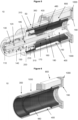
- the magnetic flux is controlled and concentrated on the coil (410), in particular on the wires of the coil (410) that cross said flux, i.e. the magnetic flux does not spread over the whole device (10), and is restricted to the area of the coil (410) so that the efficiency of the electrical current generation increases (efficient energy generation).
- ferromagnetic material such as iron or iron alloy is suitable to increase said effect.
- the device (10) for driving an endodontic file head (500) of an endodontic device (1) and operating a remote pump comprises:
- An embodiment according to the invention is related to a device (10), wherein the metal is an iron alloy.
- an embodiment according to the invention is directed to a device (10) for driving an endodontic file head (500) of an endodontic device (1) and operating a remote pump, the device comprising:
- the device comprises:
- the amount of the carbon in the iron alloy of the first cylindrical element (310) can be up to 0.2 wt%, preferably 0.15 wt%, and most preferably up to 0.1 wt%. In other words, the amount of the carbon in the iron alloy of the first cylindrical element (310, 310) is lower than 0.2 wt% carbon, more preferably lower than 0.15 wt% carbon, still more preferably lower than 0.1 wt% carbon.
- the amount of the carbon in the iron alloy of the second cylindrical element (350) can be up to 0.2 wt%, preferably 0.15 wt%, and most preferably up to 0.1 wt%. In other words, the amount of the carbon in the iron alloy of the second cylindrical element (350) is lower than 0.2 wt% carbon, more preferably lower than 0.15 wt% carbon, still more preferably lower than 0.1 wt% carbon.
- an embodiment according to the invention is directed to a device (10), wherein first cylindrical element (310) and/or the second cylindrical element (350) is made of an iron alloy, wherein the iron alloy contains carbon in an amount up to 0.2 wt%.
- an embodiment according to the invention is directed to a device (10) for driving an endodontic file head (500) of an endodontic device (1) and operating a remote pump, the device comprising:
- the device (10) for driving an endodontic file head (500) of an endodontic device (1) and operating a remote pump comprises:
- first cylindrical element (310) and/or second cylindrical element (350) is ferromagnetic.
- first cylindrical element (310) and/or second cylindrical element (350) should preferably have a ferritic structure.
- the steel AISI 1008 can be used as a material for the first cylindrical element (310) and/or second cylindrical element (350).
- the device comprises:
- An embodiment according to the invention is related to a device (10), wherein the magnet holding means (200) is a magnetic separator (205).
- an embodiment according to the invention is directed to a device (10) for driving an endodontic file head (500) of an endodontic device (1) and operating a remote pump, the device comprising:
- the device (10) for driving an endodontic file head (500) of an endodontic device (1) and operating a remote pump comprises:
- the device (10) for driving an endodontic file head (500) of an endodontic device (1) and operating a remote pump comprises:
- the device (10) for driving an endodontic file head (500) of an endodontic device (1) and operating a remote pump comprises:
- the device (10) for driving an endodontic file head (500) of an endodontic device (1) and operating a remote pump comprises:
- the device (10) for driving an endodontic file head (500) of an endodontic device (1) and operating a remote pump comprises:
- the device (10) for driving an endodontic file head (500) of an endodontic device (1) and operating a remote pump comprises:
- An embodiment according to the invention is directed to a device (10), wherein the device contains 1, 2, 3, 4, 5, 6, 7, 8, 9, 10, 11, 12, 13, 14, 15, or 16 magnets.
- the device contains 2, 4, 6, 8, 10, 12, 14, or 16 magnets. More preferably, the device contains 4, 6, 8, 10, or 12 magnets. Still more preferably, the device contains 6, 8, or 10 magnets. More preferably, the device contains at least 2 magnets, still more preferably 4 magnets, still more preferably 6 magnets, and still more preferably 8 magnets. Most preferably, the device (10) contains 8 magnets.
- an embodiment of the invention is related to a device (10) for driving an endodontic file head (500) of an endodontic device (1) and for operating a remote pump, the device comprising:
- the gear (110) is a steel bevel gear (115).
- the first cylindrical (310) element and the second cylindrical element (350) comprises a metal.
- the first cylindrical (310) element and the second cylindrical element (350) comprises an iron alloy.
- said iron alloy contains carbon in an amount up to 0.2 wt%.
- the magnet holding means (200) is a magnetic separator (205).
- the device (10) for driving an endodontic file head (500) of an endodontic device (1) and operating a remote pump comprises:
- the device (10) for driving an endodontic file head (500) of an endodontic device (1) and operating a remote pump comprises:
- the device (10) for driving an endodontic file head (500) of an endodontic device (1) and operating a remote pump comprises:
- the device (10) for driving an endodontic file head (500) of an endodontic device (1) and operating a remote pump comprises:
- the device (10) for driving an endodontic file head (500) of an endodontic device (1) and operating a remote pump comprises:
- the device (10) for driving an endodontic file head (500) of an endodontic device (1) and operating a remote pump comprises:
- a preferred embodiment according to the invention is directed to a device (10), wherein the at least one magnet (210) is made of an alloy.
- a preferred embodiment according to the invention is related to a device (10) for driving an endodontic file head (500) of an endodontic device (1) and operating a remote pump, the device comprising:
- the gear (110) is a steel bevel gear (115).
- the first cylindrical (310) element and the second cylindrical element (350) comprises a metal.
- the first cylindrical (310) element and the second cylindrical element (350) comprises an iron alloy.
- said iron alloy contains carbon in an amount up to 0.2 wt%.
- the magnet holding means (200) is a magnetic separator (205).
- the device (10) for driving an endodontic file head (500) of an endodontic device (1) and operating a remote pump comprises:
- the device (10) for driving an endodontic file head (500) of an endodontic device (1) and operating a remote pump comprises:
- the device (10) for driving an endodontic file head (500) of an endodontic device (1) and operating a remote pump comprises:
- the device (10) for driving an endodontic file head (500) of an endodontic device (1) and operating a remote pump comprises:
- the device (10) for driving an endodontic file head (500) of an endodontic device (1) and operating a remote pump comprises:
- the device (10) for driving an endodontic file head (500) of an endodontic device (1) and operating a remote pump comprises:
- a more preferred embodiment according to the invention is related to a device (10), wherein the at least one magnet (210) is made of a neodymium-iron-boron alloy.
- a still more preferred embodiment according to the invention is related to a device (10), wherein the at least one magnet (210) is made of a nickel-plated neodymium-iron-boron alloy.
- a still more preferred embodiment according to the invention is directed to a device (10) for driving an endodontic file head (500) of an endodontic device (1) and operating a remote pump, the device comprising:
- the gear (110) is a steel bevel gear (115).
- the first cylindrical (310) element and the second cylindrical element (350) comprises a metal.
- the first cylindrical (310) element and the second cylindrical element (350) comprises an iron alloy.
- said iron alloy contains carbon in an amount up to 0.2 wt%.
- the magnet holding means (200) is a magnetic separator (205).
- the device (10) for driving an endodontic file head (500) of an endodontic device (1) and operating a remote pump comprises:
- the device (10) for driving an endodontic file head (500) of an endodontic device (1) and operating a remote pump comprises:
- the device (10) for driving an endodontic file head (500) of an endodontic device (1) and operating a remote pump comprises:
- the device (10) for driving an endodontic file head (500) of an endodontic device (1) and operating a remote pump comprises:
- the device (10) for driving an endodontic file head (500) of an endodontic device (1) and operating a remote pump comprises:
- the device (10) for driving an endodontic file head (500) of an endodontic device (1) and operating a remote pump comprises:
- the at least two magnets (210) can be symmetrically arranged along the circumference of drive shaft (120), which provides strong magnetic flux loops. Symmetrically arranged means that the magnets are equidistantly positioned in the magnet holding means (200). Moreover, neighbouring (adjacent) magnets can have opposite polarity, which also provides strong magnetic flux loops. More preferably, the at least two magnets (210) are arranged symmetrically along the circumference of the drive shaft (120), and the neighbouring magnets have opposite polarity, which further increases the magnetic flux loops.
- an embodiment according to the invention is directed to a device (10) for driving an endodontic file head (500) of an endodontic device (1) and operating a remote pump, the device comprising:
- the gear (110) is a steel bevel gear (115).
- the first cylindrical (310) element and the second cylindrical element (350) comprises a metal.
- the first cylindrical (310) element and the second cylindrical element (350) comprises an iron alloy.
- said iron alloy contains carbon in an amount up to 0.2 wt%.
- the magnet holding means (200) is a magnetic separator (205).
- the device (10) for driving an endodontic file head (500) of an endodontic device (1) and operating a remote pump comprises:
- the device (10) for driving an endodontic file head (500) of an endodontic device (1) and operating a remote pump comprises:
- the device (10) for driving an endodontic file head (500) of an endodontic device (1) and operating a remote pump comprises:
- the device (10) for driving an endodontic file head (500) of an endodontic device (1) and operating a remote pump comprises:
- the device (10) for driving an endodontic file head (500) of an endodontic device (1) and operating a remote pump comprises:
- the device (10) for driving an endodontic file head (500) of an endodontic device (1) and operating a remote pump comprises:
- the device (10) for driving an endodontic file head (500) of an endodontic device (1) and operating a remote pump comprises:
- the device (10) for driving an endodontic file head (500) of an endodontic device (1) and operating a remote pump comprises:
- the device (10) for driving an endodontic file head (500) of an endodontic device (1) and operating a remote pump comprises:
- the device (10) for driving an endodontic file head (500) of an endodontic device (1) and operating a remote pump comprises:
- the device (10) for driving an endodontic file head (500) of an endodontic device (1) and operating a remote pump comprises:
- the device (10) for driving an endodontic file head (500) of an endodontic device (1) and operating a remote pump comprises:
- the device (10) for driving an endodontic file head (500) of an endodontic device (1) and operating a remote pump comprises:
- the device (10) for driving an endodontic file head (500) of an endodontic device (1) and operating a remote pump comprises:
- the device (10) for driving an endodontic file head (500) of an endodontic device (1) and operating a remote pump comprises:
- the device (10) for driving an endodontic file head (500) of an endodontic device (1) and operating a remote pump comprises:
- the device (10) for driving an endodontic file head (500) of an endodontic device (1) and operating a remote pump comprises:
- the device (10) for driving an endodontic file head (500) of an endodontic device (1) and operating a remote pump comprises:
- a preferred embodiment according to the invention is directed to a device (10) for driving an endodontic file head (500) of an endodontic device (1) and operating a remote pump, the device comprising:
- a still more preferred embodiment according to the invention is directed to a device (10) for driving an endodontic file head (500) of an endodontic device (1) and operating a remote pump, the device comprising:
- the gear (110) is a steel bevel gear (115).
- the first cylindrical (310) element and the second cylindrical element (350) comprises a metal.
- the first cylindrical (310) element and the second cylindrical element (350) comprises an iron alloy.
- said iron alloy contains carbon in an amount up to 0.2 wt%.
- the magnet holding means (200) is a magnetic separator (205).
- a still more preferred embodiment according to the invention is directed to a device (10) for driving an endodontic file head (500) of an endodontic device (1) and operating a remote pump, the device comprising:
- a still more preferred embodiment according to the invention is directed to a device (10) for driving an endodontic file head (500) of an endodontic device (1) and operating a remote pump, the device comprising:
- a still more preferred embodiment according to the invention is directed to a device (10) for driving an endodontic file head (500) of an endodontic device (1) and operating a remote pump, the device comprising:
- the magnet holding means (200), particularly the magnetic separator (205), can be made of any material, which is not ferromagnetic, paramagnetic or diamagnetic.
- the material is preferably a polymer.
- the polymer is resistant of aqueous acids, aqueous bases and/or alcohols. More preferably, the polymer is resistant to aqueous acids namely hydrochloric acid and phosphoric acids.
- the polymer can be a thermosetting polymer (thermoset) or thermosoftening plastic (thermoplastic).
- the polymer is an organic polymer.
- the polymer can be selected from the group comprising or consisting of acrylonitrile butadiene styrene copolymer (ABS), acrylonitrile styrene (ANS), cellulose acetate, cellulose acetate butyrate, cellulose acetate propionate, cellulose acetate phthalate, cellulose nitrate, cyclic olefin copolymer, poly(ethene-co-tetrafluoroethene), poly(ethene-co-chlorortrifluoroethene), fluorinated ethylene propylene, polystyrene, high impact polystyrene, polybutylene adipate terephthalate, polybutylene succinate, polybutylene terephthalate, polycarbonate, polychlorotrifluoroethylene, polyethylene terephthalate, polylactide, polyethylene naphthalate, polyetherimide, polyetherketones (PEK) such as
- the polymer is selected from the group comprising or consisting of acrylonitrile butadiene styrene copolymer (ABS), acrylonitrile styrene (ANS), cellulose acetate, cellulose acetate butyrate, cellulose acetate propionate, cellulose acetate phthalate, cellulose nitrate, cyclic olefin copolymer, poly(ethene-co-tetrafluoroethene), poly(ethene-co-chlorortrifluoroethene), fluorinated ethylene propylene, polystyrene, high impact polystyrene, polybutylene adipate terephthalate, polybutylene succinate, polybutylene terephthalate, polycarbonate, polychlorotrifluoroethylene, polyethylene terephthalate, polylactide, polyethylene naphthalate, polyetherimide, polyetherketones (PEK)
- ABS
- the polymer is selected from the group comprising or consisting of acrylonitrile butadiene styrene copolymer (ABS), acrylonitrile styrene (ANS), polyphthalamide, poly(ethene-co-tetrafluoroethene), polycarbonate, polyethylene, polyimide, polystyrene, and polyvinyl chloride. Still more preferably, the polymer is selected from the group comprising or consisting of acrylonitrile butadiene styrene copolymer (ABS), acrylonitrile styrene (ANS), polyphthalamide, and polycarbonate. The polymer is most preferably acrylonitrile butadiene styrene copolymer (ABS).
- PCB Printed circuit board
- An embodiment according to the invention is related to a device (10), wherein the inner encoder (430) on the central processing (420) unit for measuring the velocity of the drive shaft is implemented by means of the central processing unit (420) counting the time that passes between threshold crossing of the sine wave being generated in the coil (410), which is proportional to the velocity of the drive shaft (120). More precisely, the time that passes between threshold crossing of the sine wave being generated in the coil is proportional to the rotational speed of the drive shaft.
- an embodiment according to the invention is directed to a device (10) for driving an endodontic file head (500) of an endodontic device (1) and operating a remote pump, the device comprising:
- the device (10) for driving an endodontic file head (500) of an endodontic device (1) and operating a remote pump comprises:
- the device (10) for driving an endodontic file head (500) of an endodontic device (1) and operating a remote pump comprises:
- the device (10) for driving an endodontic file head (500) of an endodontic device (1) and operating a remote pump comprises:
- the device (10) for driving an endodontic file head (500) of an endodontic device (1) and operating a remote pump comprises:
- the device (10) for driving an endodontic file head (500) of an endodontic device (1) and operating a remote pump comprises:
- the device (10) for driving an endodontic file head (500) of an endodontic device (1) and operating a remote pump comprises:
- the device (10) for driving an endodontic file head (500) of an endodontic device (1) and operating a remote pump comprises:
- the device (10) for driving an endodontic file head (500) of an endodontic device (1) and operating a remote pump comprises:
- the device (10) for driving an endodontic file head (500) of an endodontic device (1) and operating a remote pump comprises:
- the device (10) for driving an endodontic file head (500) of an endodontic device (1) and operating a remote pump comprises:
- the device (10) for driving an endodontic file head (500) of an endodontic device (1) and operating a remote pump comprises:
- the device (10) for driving an endodontic file head (500) of an endodontic device (1) and operating a remote pump comprises:
- the device (10) for driving an endodontic file head (500) of an endodontic device (1) and operating a remote pump comprises:
- the device (10) for driving an endodontic file head (500) of an endodontic device (1) and operating a remote pump comprises:
- the device (10) for driving an endodontic file head (500) of an endodontic device (1) and operating a remote pump comprises:
- the device (10) for driving an endodontic file head (500) of an endodontic device (1) and operating a remote pump comprises:
- the device (10) for driving an endodontic file head (500) of an endodontic device (1) and operating a remote pump comprises:
- the device (10) for driving an endodontic file head (500) of an endodontic device (1) and operating a remote pump comprises:
- the device (10) for driving an endodontic file head (500) of an endodontic device (1) and operating a remote pump comprises:
- the device (10) for driving an endodontic file head (500) of an endodontic device (1) and operating a remote pump comprises:
- the gear (110) is a steel bevel gear (115).
- the first cylindrical (310) element and the second cylindrical element (350) comprises a metal.
- the first cylindrical (310) element and the second cylindrical element (350) comprises an iron alloy.
- said iron alloy contains carbon in an amount up to 0.2 wt%.
- the magnet holding means (200) is a magnetic separator (205).
- the device comprises at least two magnets (210), more preferably eight magnets (210).
- the magnet(s) (210) are made of a nickel-plated neodymium-iron-boron alloy.
- the AC voltage that is generated by the coil goes into the central processing unit (420) preferably via a protection circuit to avoid reaching central processing unit input limitations. Said input is used to measure the rotation speed.
- the AC voltage is rectified preferably by means of diodes and capacitors in order to feed the DC-DC circuit. The rotation speed is thus measured by using the AC voltage of the coil, while the power supply circuits use the rectified DC voltage.
- An embodiment is directed to a device (10), wherein the coil (410), the central processing unit (420), the inner encoder (430), the transmitter (450), and the antenna (460) are on a printed circuit board (400).
- the integration of the coil into the printed circuit board (400) is essential since no space for regular coils is present in an endodontic device (1) or of the device (10) having a reduced volume is available.
- coils are easier to manufacture when being printed on a printed circuit board in comparison to conventional thin wire winding technology.
- assembly of the device (10) is facilitated by using the PCB (400) having the coil (410) printed on it, instead of a coil custom made by wire winding.
- a coil custom made by wire winding is less reliable than a coil (410) printed in multiple layers on a printed circuit board (400).
- the coil is printed on the printed circuit board.
- An AC voltage is induced in the coil printed on the printed circuit board (400) by rotation of the at least one magnet in the rotatable magnet holding means (200).
- adjacent magnets of the at least one magnet (210) fixed in the rotatable magnet holding means (200) are of opposite polarity, thereby generating alternating current.
- the coil therefore acts as an inductor on the PCB.
- the coil is preferably made of an electrically conductive material, such as copper.
- the cross section of the coil has preferably the shape of a rectangle.
- the number of coils can be in the range of 3 to 10, preferably in the range of 4 to 8, and most preferably in the range of 4 to 6.
- a lower number of coils as stated above adversely affects the performance since not enough power is generated for activating the current electronics.
- a larger number of coils as stated above is more costly to produce and a flexible PCB with such a number of coils is difficult to place into the inventive device.
- the printed circuit board (400) comprises six coils.
- the coils are printed on top of each other so that they are located exactly at the same position on the printed circuit board.
- the printed circuit board (400) comprises six coils, which are printed on top of each other.
- each coil is printed as an individual layer on the PCB (400).
- the number of layers can be in the range of 3 to 10, preferably in the range of 4 to 8, and most preferably in the range of 4 to 6.
- the printed circuit board (400) comprises six layers.
- the printed coil can be of any pattern, such as wavy line pattern, S-shape pattern, snake shape pattern, rectangular snake shape pattern, or square wave pattern. Since the voltage induction is most efficient in sections of the coil, which are oriented parallel to the axis of rotation of the drive shaft (120) and the rotatable magnet holding means (200), those patterns are preferred that result in the largest sections of the coil, which are oriented in parallel to the axis of rotation.
- the coil comprises a square wave pattern as depicted in Figure 15 .
- the coil is not spiral shaped.
- the coil (410) is square wave shaped, wherein the shape is defined by the parameters A, B and C (see Figure 16 ).
- A represents closest distance between the center line B and the square wave pattern and P represents the length of each segment of the square wave pattern.
- P lies in the range of 3 mm to 7 mm, more preferably in the range of 4 mm to 6.5 mm and most preferably in the range of 5 mm to 6 mm. In a preferred embodiment, P is about 5.55 mm.
- A lies in the range of 2 mm to 6 mm, more preferably in the range of 2.5 mm to 5 mm and most preferably in the range of 3 mm to 4 mm. In a preferred embodiment, A is about 3 mm.
- A is about 3 mm and P is about 5.55 mm.
- the square wave shaped coil consists of 7 to 15 periods (windings), more preferably of 8 to 14 periods, more preferably of 9 to 13 periods, and most preferably of 10 to 12 periods. Particularly preferred is a square wave shaped coil of 11 periods.
- the number of the periods of the square wave shaped coil is identical to the number of the at least one magnet (210) fixed in the rotatable magnet holding means (200).
- a larger value of A is preferred.
- a value of P is preferred which is identical or nearly identical to the distance of the adjacent magnets of the at least one magnet (210) fixed in the rotatable magnet holding means (200).
- the effective length of each printed coil can be in the range of 1000 mm to 1800 mm, preferably in the range of 1200 mm to 1600 mm, more preferably 1300 mm to 1500 mm. Preferably, the effective length of each printed coil is about 1420 mm.
- an embodiment according to the invention is related to a device (10) for driving an endodontic file head (500) of an endodontic device (1) and operating a remote pump, the device comprising:
- the gear (110) is a steel bevel gear (115).
- the first cylindrical (310) element and the second cylindrical element (350) comprises a metal.
- the first cylindrical (310) element and the second cylindrical element (350) comprises an iron alloy.
- said iron alloy contains carbon in an amount up to 0.2 wt%.
- the magnet holding means (200) is a magnetic separator (205).
- the device comprises at least two magnets (210), more preferably eight magnets (210).
- the magnet(s) (210) are made of a nickel-plated neodymium-iron-boron alloy.
- the inventive device (10) for driving an endodontic file head (500) of an endodontic device (1) and operating a remote pump comprises:
- An embodiment according to the invention is directed to a device (10), wherein the coil (410), the central processing unit (420), the inner encoder (430), the transmitter (450), and the antenna (460) are on a flexible printed circuit board (400).
- the printed circuit board (400) is made of a flexible material, such as polyamide.
- an embodiment according to the invention is related to a device (10) for driving an endodontic file head (500) of an endodontic device (1) and operating a remote pump, the device comprising:
- An embodiment according to the invention is related to a device (10), wherein the device contains a DC-DC converter (470).
- an embodiment according to the invention is directed to a device (10) for driving an endodontic file head (500) of an endodontic device (1) and operating a remote pump, the device comprising:
- the gear (110) is a steel bevel gear (115).
- the first cylindrical (310) element and the second cylindrical element (350) comprises a metal.
- the first cylindrical (310) element and the second cylindrical element (350) comprises an iron alloy.
- said iron alloy contains carbon in an amount up to 0.2 wt%.
- the magnet holding means (200) is a magnetic separator (205).
- the device comprises at least two magnets (210), more preferably eight magnets (210).
- the magnet(s) (210) are made of a nickel-plated neodymium-iron-boron alloy.
- An embodiment according to the invention is directed to a device (10), wherein the DC-DC converter (470) contains a maximum power point tracking algorithm. Thereby, the voltage level can be further improved.
- MPPT Maximum Power Point Tracking
- the concept is: to efficiently harvest energy from the coil, the device should neither seek for high current, nor high voltage, but rather seek for maximum power, which is the product of the current multiplied by the voltage.
- the DC-DC converter (470) which is fed by the coil energy, sweeps through certain ranges of current drawn from the coil, causing changes in the coil voltage. (In case of a low current, a light load exists and the voltage is higher. In case of a high current, a heavy load exists, and the voltage is lower).
- the power (product of current and voltage) is calculated along this sweep, the maximum power is recorded, and the DC-DC converter goes back to consume the current that corresponds to the maximum power point.
- the DC-DC converter keeps tracking this maximum power point, by actively changing the current consumed from the source (coil) and monitoring the voltage.
- the DC-DC converter (470) comprises a MPPT charge controller.
- an embodiment according to the invention is related to a device (10) for driving an endodontic file head (500) of an endodontic device (1) and operating a remote pump, the device comprising:
- the gear (110) is a steel bevel gear (115).
- the first cylindrical (310) element and the second cylindrical element (350) comprises a metal.
- the first cylindrical (310) element and the second cylindrical element (350) comprises an iron alloy.
- said iron alloy contains carbon in an amount up to 0.2 wt%.
- the magnet holding means (200) is a magnetic separator (205).
- the device comprises at least two magnets (210), more preferably eight magnets (210).
- the magnet(s) (210) are made of a nickel-plated neodymium-iron-boron alloy.
- the central processing unit (420), the inner encoder (430), the transmitter (450), and the antenna (460) can be surrounded by an outer ring positioner (1000).
- This outer ring positioner (1000) will cover and protect said components.
- the outer ring positioned (1000) surrounds part of the PCB apart from the coil part.
- the outer ring positioned can be made of any material.
- the material is a polymer.
- the polymer is resistant of aqueous acids, aqueous bases and/or alcohols.
- the polymer is resistant to aqueous acids namely hydrochloric acid and phosphoric acids.
- the polymer can be a thermosetting polymer (thermoset) or thermosoftening plastic (thermoplastic).
- thermoplastic thermoplastic
- the polymer is an organic polymer.
- the polymer can be selected from the group comprising or consisting of acrylonitrile butadiene styrene copolymer (ABS), acrylonitrile styrene (ANS), cellulose acetate, cellulose acetate butyrate, cellulose acetate propionate, cellulose acetate phthalate, cellulose nitrate, cyclic olefin copolymer, poly(ethene-co-tetrafluoroethene), poly(ethene-cochlorortrifluoroethene), fluorinated ethylene propylene, polystyrene, high impact polystyrene, polybutylene adipate terephthalate, polybutylene succinate, polybutylene terephthalate, polycarbonate, polychlorotrifluoroethylene, polyethylene terephthalate, polylactide, polyethylene naphthalate, polyetherimide, polyetherketones (PEK) such as poly
- the polymer is selected from the group comprising or consisting of acrylonitrile butadiene styrene copolymer (ABS), acrylonitrile styrene (ANS), cellulose acetate, cellulose acetate butyrate, cellulose acetate propionate, cellulose acetate phthalate, cellulose nitrate, cyclic olefin copolymer, poly(ethene-co-tetrafluoroethene), poly(ethene-cochlorortrifluoroethene), fluorinated ethylene propylene, polystyrene, high impact polystyrene, polybutylene adipate terephthalate, polybutylene succinate, polybutylene terephthalate, polycarbonate, polychlorotrifluoroethylene, polyethylene terephthalate, polylactide, polyethylene naphthalate, polyetherimide, polyetherketones (PEK) such
- the polymer is selected from the group comprising or consisting of acrylonitrile butadiene styrene copolymer (ABS), acrylonitrile styrene (ANS), polyphthalamide, poly(ethene-co-tetrafluoroethene), polycarbonate, polyethylene, polyimide, polystyrene, and polyvinyl chloride. Still more preferably, the polymer is selected from the group comprising or consisting of acrylonitrile butadiene styrene copolymer (ABS), acrylonitrile styrene (ANS), polyphthalamide, and polycarbonate. The polymer is most preferably acrylonitrile butadiene styrene copolymer (ABS).
- An embodiment according to the invention is directed to a device (10), wherein the device further comprises at least one battery (800).
- an embodiment according to the invention is related to a device (10) for driving an endodontic file head (500) of an endodontic device (1) and operating a remote pump, the device comprising:
- the gear (110) is a steel bevel gear (115).
- the first cylindrical (310) element and the second cylindrical element (350) comprises a metal.
- the first cylindrical (310) element and the second cylindrical element (350) comprises an iron alloy.
- said iron alloy contains carbon in an amount up to 0.2 wt%.
- the magnet holding means (200) is a magnetic separator (205).
- the device comprises at least two magnets (210), more preferably eight magnets (210).
- the magnet(s) (210) are made of a nickel-plated neodymium-iron-boron alloy.
- the battery can help to reduce the waiting period before using the device (10) by 1.0 to 1.5 milliseconds, which is significant for surgeon.
- the space in an endodontic device is limited in a manner that the generation of a high voltage relative to the dimension is challenging.
- a voltage of 4.2 V is necessary.
- it is particularly difficult to provide a voltage of 4.2 V in the dimension of the endodontic device (1). Reducing the waiting period before using the device (10) by 1.0 to 1.5 milliseconds by faster charging a battery is significant for a surgeon.
- a further embodiment according to the invention is related to a device (10), wherein the device (10) further comprises at least one rechargeable battery (810). Therefore, a further embodiment according to the invention is directed to a device (10) for driving an endodontic file head (500) of an endodontic device (1) and operating a remote pump, the device comprising:
- the energy generated by the use of device (10) can be used for another treatment in order to reduce the waiting period before using the device (10) by 1.0 to 1.5 milliseconds, which is significant for surgeon.
- At least one battery (800) is not fixed on the printed circuit board (400) or flexible printed circuit board (405) of the device (10).
- an embodiment is directed to a device (10) for driving an endodontic file head (500) of an endodontic device (1) and operating a remote pump, the device comprising:
- At least one rechargeable battery (810) is not fixed on the printed circuit board (400) of the device (10).
- another preferred embodiment according to the invention is directed to a device (10) for driving an endodontic file head (500) of an endodontic device (1) and operating a remote pump, the device comprising:
- the printed circuit board (400) may contain a battery connection (850) if a battery is used.
- the printed circuit board (400) may contain a capacitor connection (880) if a capacitor (860) is used.
- the rechargeable battery can be a lithium-ion polymer battery also called lithium polymer battery, which utilizes a polymer electrolyte. High conductivity semisolid gels or polymers form this electrolyte. These batteries provide higher specific energy than other lithium battery types.
- the weight of the device (10) can be reduced by using a lithium-ion polymer battery.
- the voltage of the lithium-ion polymer battery is preferably between 2.7 V to 3.7 V in a discharged state, more preferably 3.0 to 3.7V, still more preferably 3.5 V to 3.7 V, and still more preferably 3.7 V.
- the battery has preferably a capacity of 9 mAh.
- the device (10) further comprises at least one battery charger (900).
- a further embodiment according to the invention is directed to a device (10) for driving an endodontic file head (500) of an endodontic device (1) and operating a remote pump, the device comprising:
- a DC-DC converter (470) can charge the battery, and thus function as a battery charger (900).
- the DC-DC converter (470) comprises then two outputs, one for the battery and one output for the transmitter.
- Power can be provided to the transmitter from one of the available power sources: either the coil or the battery, with the coil having precedence over the battery.
- the DC-DC converter (470) is adapted in such a way that if the coil has enough power for both, it will be the power source for battery charging and the transmitter, otherwise, the battery will power the transmitter.
- a preferred embodiment according to the invention is directed to a device (10) for driving an endodontic file head (500) of an endodontic device (1) and operating a remote pump, the device comprising:
- a preferred embodiment according to the invention is directed to a device (10) for driving an endodontic file head (500) of an endodontic device (1) and operating a remote pump, the device comprising:
- a preferred embodiment according to the invention is directed to a device (10) for driving an endodontic file head (500) of an endodontic device (1) and operating a remote pump, the device comprising:
- a more preferred embodiment according to the invention is directed to a device (10) for driving an endodontic file head (500) of an endodontic device (1) and operating a remote pump, the device comprising:
- a still more preferred embodiment according to the invention is directed to a device (10) for driving an endodontic file head (500) of an endodontic device (1) and operating a remote pump, the device comprising:
- the use of the battery voltage does not influence the measuring of the rotation speed since the AC voltage is used for this purpose while the battery produces a DC voltage.
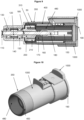
- Another embodiment according to the invention is directed to a device (10), wherein the device does not comprise a battery (800) or a rechargeable battery (810) (see Figures 9-11 ).
- an embodiment according to the invention is related to a device (10) for driving an endodontic file head (500) of an endodontic device (1) and operating a remote pump, the device comprising:
- the gear (110) is a steel bevel gear (115).
- the first cylindrical (310) element and the second cylindrical element (350) comprises a metal.
- the first cylindrical (310) element and the second cylindrical element (350) comprises an iron alloy.
- said iron alloy contains carbon in an amount up to 0.2 wt%.
- the magnet holding means (200) is a magnetic separator (205).
- the device comprises at least two magnets (210), more preferably eight magnets (210).
- the magnet(s) (210) are made of a nickel-plated neodymium-iron-boron alloy.
- an embodiment according to the invention is related to a device (10) for driving an endodontic file head (500) of an endodontic device (1) and operating a remote pump, the device comprising:
- the gear (110) is a steel bevel gear (115).
- the first cylindrical (310) element and the second cylindrical element (350) comprises a metal.
- the first cylindrical (310) element and the second cylindrical element (350) comprises an iron alloy.
- said iron alloy contains carbon in an amount up to 0.2 wt%.
- the magnet holding means (200) is a magnetic separator (205).
- the device comprises at least two magnets (210), more preferably eight magnets (210).
- the magnet(s) (210) are made of a nickel-plated neodymium-iron-boron alloy.
- the device (10) according to the invention further comprises at least one capacitor (860).
- an embodiment according to the invention is related to a device (10) for driving an endodontic file head (500) of an endodontic device (1) and operating a remote pump, the device comprising:
- the one or more capacitors serve as power storage (power capacitor), like the battery (800), and can help to reduce the waiting period before using the device (10) by 1.0 millisecond to 1.5 milliseconds, which is significant for surgeon.
- the battery (800) may be replaced by one or more capacitors (860).
- the at least one capacitor (860) is preferably selected from, but not limited to: ceramic capacitors constructed of two or more alternating layers of ceramic and a metal layer acting as the electrodes, multilayer ceramic capacitors (MLCCs), or Tantalum polymer capacitors. Given the limited available space of device (10), a capacitor of high volumetric efficiency is particularly preferred. Volumetric efficiency quantifies the performance of energy stored per unit volume and is calculated by multiplying the capacitance (C) by the maximum voltage rating (V), divided by the volume.
- an embodiment according to the invention is related to a device (10) for driving an endodontic file head (500) of an endodontic device (1) and operating a remote pump, the device comprising:
- these embodiments do not comprise a battery (800).
- an embodiment according to the invention is related to a device (10) for driving an endodontic file head (500) of an endodontic device (1) and operating a remote pump, the device comprising:
- the space in an endodontic device is limited in a manner that the generation of a high voltage relative to the dimension is challenging.
- a voltage of 4.2 V is necessary.
- it is particularly difficult to provide a voltage of 4.2 V in the dimension of the endodontic device (1). Reducing the waiting period before using the device (10) by 1.0 to 1.5 milliseconds by faster charging a battery is significant for a surgeon.
- the capacitor (860) has a capacitance of at least 400 ⁇ F, more preferably 415 ⁇ P, more preferably 430 ⁇ F and most preferably 450 ⁇ F.
- an embodiment according to the invention is related to a device (10) for driving an endodontic file head (500) of an endodontic device (1) and operating a remote pump, the device comprising:
- the at least one capacitor (860) has a capacitance in the range of 400 ⁇ F to 550 ⁇ F, more preferably in the range of 410 ⁇ F to 540 ⁇ F, more preferably in the range of 420 ⁇ F to 530 ⁇ F, more preferably in the range of 430 ⁇ F to 520 ⁇ F and most preferably in the range of 450 ⁇ F to 050 ⁇ F.
- the device (10) for driving an endodontic file head (500) of an endodontic device (1) and operating a remote pump comprises 2, 3, 4 or 5 capacitors (860).
- the device (10) comprises three capacitors (860).
- an embodiment according to the invention is related to a device (10) for driving an endodontic file head (500) of an endodontic device (1) and operating a remote pump, the device comprising:
- the three capacitors have a total capacitance between 450 ⁇ F and 500 ⁇ F.
- the device (10) comprises a capacitor having a capacitance of 47 ⁇ F and two capacitors each having a capacitance of 220 ⁇ F.
- the at least one capacitor (860) is located on the printed circuit board (400) at the outer ring (1000). In embodiments of the device (10) comprising more than one capacitor, it is preferred that all capacitors are located on the printed circuit board (400) at the outer ring (1000). Thus, it is preferred that the at least one capacitor (860) has the same position as the battery (800) in Figures 5 - 8 .
- the printed circuit board (400) may contain a capacitor charger (870) if one or more capacitors are used.
- a DC-DC converter (470) can charge the capacitor, and thus function as a capacitor charger (870).
- the DC-DC converter (470) comprises then two outputs, one for the capacitor and one output for the transmitter. Power can be provided to the transmitter from one of the available power sources: either the coil or the capacitor, with the coil having precedence over the capacitor.
- the DC-DC converter (470) is adapted in such a way that if the coil has enough power for both, it will be the power source for capacitor charging and the transmitter, otherwise, the capacitor will power the transmitter.
- a preferred embodiment according to the invention is directed to a device (10) for driving an endodontic file head (500) of an endodontic device (1) and operating a remote pump, the device comprising:
- a preferred embodiment according to the invention is directed to a device (10) for driving an endodontic file head (500) of an endodontic device (1) and operating a remote pump, the device comprising:
- a still more preferred embodiment according to the invention is directed to a device (10) for driving an endodontic file head (500) of an endodontic device (1) and operating a remote pump, the device comprising:
- the use of the capacitor voltage does not influence the measuring of the rotation speed since the AC voltage is used for this purpose while the capacitor produces a DC voltage.
- the sleeve (150) for moving the drive shaft (120) by a motorized power handle (600) can be an ISO-type connector typical in the endodontic field.
- the connector can be composed of any material.
- the material is preferably not ferromagnetic.
- the sleeve (150) is composed of iron or iron alloy, more preferably iron alloy.
- the iron alloy can be steel, and more preferably stainless steel. It is preferred if the iron or iron alloy is not ferromagnetic.
- the steel is thus preferably an austenite, and more preferably stainless steel austenite.
- the austenite can be AISI 316 (SAE 316). Still more preferably, the steel is AISI 316.
- the sleeve (150) is made of an AISI 316 annealed stainless steel bar.
- the sleeve (150) is connectable to a securing cup (160), wherein the securing cup (160) directly surrounds the part of the connector, and the securing cup (160) is positioned between the magnet holding means (200) and the sleeve (150).
- the securing cup can be made of any material. The material is preferably not ferromagnetic.
- the securing cup (160) is composed of iron or iron alloy, more preferably iron alloy.
- the iron alloy can be steel, and more preferably stainless steel. It is preferred if the iron or iron alloy is not ferromagnetic.
- the steel is thus preferably an austenite, and more preferably stainless steel austenite.
- the steel can be a chromium-nickel steel, preferably AISI 316 (SAE 316). Still more preferably, the steel is AISI 316. Most preferably, the securing cup (160) is made of an AISI 316 annealed stainless steel bar.
- the device (10) can contain an adapter (190) for connecting a motorized power handle (600) to the device (10).
- an ISO type motor adaptor Preferably, an ISO type motor adaptor.
- the adaptor can be made of any material. However, it is preferred if the material is non-ferromagnetic and/or non-paramagnetic as well as lowparamagnetic.
- the material can be aluminium or aluminium alloy, more preferably aluminium alloy, and still preferably A6061 aluminium alloy, and most preferably A6061-T6 aluminium alloy.
- the number of the aluminium alloy follows the UNS-numbering (Unified Numbering System for Metals and Alloys)
- device (10) according to the invention can contain a spring (170).
- the spring can be positioned between the magnet holding mean (200) and the securing cap (160).
- the spring (170) can be composed of steel.
- the spring (170) is composed of stainless steel. More preferably, the spring (170) is made of spring steel. Still more preferably, the spring (170) is made of steel according to EN 10151:2002 or EN10270-3:2001 (DIN 17224).
- the spring serves to couple the sleeve (150) with the motorized power handle (600). Thereby, the spring pushes the sleeve (150) against the shaft of the motorized power handle (600) in order to create a mechanical engagement between the sleeve (150) and the shaft of the motorized power handle (600).
- the housing (50) of the device (10) which encases the components of the device (10) according to the invention can be made of a polymer.
- the polymer is resistant of aqueous acids, aqueous bases and/or alcohols. More Preferably, the polymer is resistant to aqueous acids namely hydrochloric acid and phosphoric acids.
- the polymer can be a thermosetting polymer (thermoset) or thermosoftening plastic (thermoplastic).
- the polymer is an organic polymer.
- the polymer can be selected from the group comprising or consisting of acrylonitrile butadiene styrene copolymer (ABS), acrylonitrile styrene (ANS), cellulose acetate, cellulose acetate butyrate, cellulose acetate propionate, cellulose acetate phthalate, cellulose nitrate, cyclic olefin copolymer, poly(etheneco-tetrafluoroethene), poly(ethene-co-chlorortrifluoroethene), fluorinated ethylene propylene, polystyrene, high impact polystyrene, polybutylene adipate terephthalate, polybutylene succinate, polybutylene terephthalate, polycarbonate, polychlorotrifluoroethylene, polyethylene terephthalate, polylactide, polyethylene naphthalate, polyetherimide, polyetherketones (PEK) such as poly
- the polymer is selected from the group comprising or consisting of acrylonitrile butadiene styrene copolymer (ABS), acrylonitrile styrene (ANS), cellulose acetate, cellulose acetate butyrate, cellulose acetate propionate, cellulose acetate phthalate, cellulose nitrate, cyclic olefin copolymer, poly(etheneco-tetrafluoroethene), poly(ethene-co-chlorortrifluoroethene), fluorinated ethylene propylene, polystyrene, high impact polystyrene, polybutylene adipate terephthalate, polybutylene succinate, polybutylene terephthalate, polycarbonate, polychlorotrifluoroethylene, polyethylene terephthalate, polylactide, polyethylene naphthalate, polyetherimide, polyetherketones (PEK) such
- the polymer is selected from the group comprising or consisting of acrylonitrile butadiene styrene copolymer (ABS), acrylonitrile styrene (ANS), polyphthalamide, poly(ethene-co-tetrafluoroethene), polycarbonate, polyethylene, polyimide, polystyrene, and polyvinyl chloride. Still more preferably, the polymer is selected from the group comprising or consisting of acrylonitrile butadiene styrene copolymer (ABS), acrylonitrile styrene (ANS), polyphthalamide, and polycarbonate. The polymer is most preferably acrylonitrile butadiene styrene copolymer (ABS).
- the coil (410), the central processing unit (420), the inner encoder (430), the transmitter (450), and the antenna (460) can be fixed on an electrical circuit housing (480). More preferably, the coil (410), the central processing unit (420), the inner encoder (430), the transmitter (450), the antenna (460), and the DC-DC converter (470) are fixed on an electrical circuit housing (480).
- the printed circuit board (400) is preferably fixed on an electrical circuit housing (480). More preferably, the printed circuit board (400) containing the coil (410), the central processing unit (420), the inner encoder (430), the transmitter (450), and the antenna (460) are fixed on an electrical circuit housing (480). Still more preferably, the printed circuit board (400) containing the coil (410), the central processing unit (420), the inner encoder (430), the transmitter (450), the antenna (460), and the DC-DC converter are fixed on an electrical circuit housing (480).
- the electrical circuit housing (480) can be composed of any material.
- the material is not ferromagnetic, paramagnetic or diamagnetic.
- the material is preferably a polymer.
- the polymer is resistant of aqueous acids, aqueous bases and/or alcohols. More Preferably, the polymer is resistant to aqueous acids namely hydrochloric acid and phosphoric acids.
- the polymer can be a thermosetting polymer (thermoset) or thermosoftening plastic (thermoplastic).
- the polymer is an organic polymer.
- the polymer can be selected from the group comprising or consisting of acrylonitrile butadiene styrene copolymer (ABS), acrylonitrile styrene (ANS), cellulose acetate, cellulose acetate butyrate, cellulose acetate propionate, cellulose acetate phthalate, cellulose nitrate, cyclic olefin copolymer, poly(ethene-co-tetrafluoroethene), poly(ethene-cochlorortrifluoroethene), fluorinated ethylene propylene, polystyrene, high impact polystyrene, polybutylene adipate terephthalate, polybutylene succinate, polybutylene terephthalate, polycarbonate, polychlorotrifluoroethylene, polyethylene terephthalate, polylactide, polyethylene naphthalate, polyetherimide, polyetherketones (PEK) such as poly
- the polymer is selected from the group comprising or consisting of acrylonitrile butadiene styrene copolymer (ABS), acrylonitrile styrene (ANS), cellulose acetate, cellulose acetate butyrate, cellulose acetate propionate, cellulose acetate phthalate, cellulose nitrate, cyclic olefin copolymer, poly(ethene-co-tetrafluoroethene), poly(ethene-cochlorortrifluoroethene), fluorinated ethylene propylene, polystyrene, high impact polystyrene, polybutylene adipate terephthalate, polybutylene succinate, polybutylene terephthalate, polycarbonate, polychlorotrifluoroethylene, polyethylene terephthalate, polylactide, polyethylene naphthalate, polyetherimide, polyetherketones (PEK) such
- the polymer is selected from the group comprising or consisting of acrylonitrile butadiene styrene copolymer (ABS), acrylonitrile styrene (ANS), polyphthalamide, poly(ethene-co-tetrafluoroethene), polycarbonate, polyethylene, polyimide, polystyrene, and polyvinyl chloride. Still more preferably, the polymer is selected from the group comprising or consisting of acrylonitrile butadiene styrene copolymer (ABS), acrylonitrile styrene (ANS), polyphthalamide, and polycarbonate. The polymer is most preferably acrylonitrile butadiene styrene copolymer (ABS).
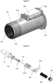
- the drive shaft 120 can be linked to the other components of the rotator part (100) of the device (10) by a pin (180).
- the pin (180) can be composed of any material. The material is preferably not ferromagnetic.
- the drive shaft (120) is composed of iron or iron alloy, more preferably iron alloy.
- the iron alloy can be steel, and more preferably stainless steel. It is preferred if the iron or iron alloy is not ferromagnetic.
- the steel is thus preferably an austenite, and more preferably stainless steel austenite.
- the steel can be chromium-nickel steel, preferably AISI 316 (SAE 316). Still more preferably, the steel is AISI 316.
- the pin (180) is made of an AISI 316 annealed stainless steel bar.
- the drive shaft (120) can be linked by a pin (180) to the sleeve (150).
- the magnet holding means (200) can be linked to the drive shaft (120) by a pin (185).
- the pin interconnecting the magnet holding means (200) and the drive shaft (120) is a slotted spring pin.
- the slotted spring pin can be made of steel, and preferably stainless steel.
- the steel can have an austenitic structure.
- the steel is not ferromagnetic.
- the steel can be a chromiumnickelsteel, preferably, the steel is 18-8 stainless steel (AISI/SAE 304).
- the alloy AISI 1008/SAE 1008 (material number: 1.0034; UNS: G10080) has the following composition: 0.3 - 0.5 wt% Mn ⁇ 0.05 wt% S ⁇ 0.04 wt% P ⁇ 0.1 wt% C Balance to 100 wt% Fe
- the alloy AISI/SAE 440C (Material number 1.4125; DIN 17740, UNS: S44004, EN material designation: X105CrMo17) has the following composition: 16.0 wt% - 18.0 wt% Cr ⁇ 0.8 wt% Mo ⁇ 1.0 wt% Mn ⁇ 0.04 wt% S ⁇ 0.04 wt% P ⁇ 1.0 wt% Si 0.95 wt - 1.20 wt% C Balance to 100 wt% Fe
- the alloy AISI/SAE 440c has the following composition: 16.0 wt% - 18.0 wt% Cr 0.4 - 0.8 wt% Mo ⁇ 1.0 wt% Mn ⁇ 0.04 wt% S ⁇ 0.04 wt% P ⁇ 1.0 wt% Si 0.95 wt - 1.20 wt% C Balance to 100 wt% Fe
- the alloy AISI 316 / SAE 316 (Material number: 1.4401; EN material designation: X5CrNiMo 17-12-2; UNS 31600) has the following composition: 16.5 - 18.5 wt% Cr 2.0 - 2.5 wt% Mo 10.0 - 13.0 wt% Ni ⁇ 2.0 wt% Mn ⁇ 0.015 wt% S ⁇ 0.011 wt% N ⁇ 0.045 wt% P ⁇ 1.0 wt% Si ⁇ 0.07 wt% C Balance to 100 wt% Fe
- the alloy 18/8 (18-8; AISI/SAE 304; material no. 1.4301; UNS: S30400) has the following composition: 17.5 - 19.5 wt% Cr 8.0 - 10.5 wt% Ni ⁇ 2.0 wt% Mn ⁇ 0.015 wt% S ⁇ 0.011 wt% N ⁇ 0.045 wt% P ⁇ 1.0 wt% Si ⁇ 0.07 wt% C Balance to 100 wt% Fe
- DIN17224 (EN 10151:2002 or EN10270-3:2001) refers to stainless steel strip for springs (technical delivery conditions) or steel wire for mechanical springs (part 3: stainless spring steel wire).
- the spring can be composed of an alloy such as X10CrNi18-8 (material no. 1.4310), X11CrMnNiN19-8-6 (material no. 1.4369), X12CrMnNiN17-7-5 (material no. 1.4372), X20Cr13 (material no.1.4021), X30Cr13 (material no. 1.4028), X39Cr13 (material no. 1.4031), X5CrNi18-10 (material no.
- the steel X10CrNi18-8 (material no. 1.4310) has the following composition: 16.0 - 19.0 wt% Cr 6.0 - 9.5 wt% Ni ⁇ 2.0 wt% Mn ⁇ 0.8 wt% Mo ⁇ 0.015 wt% S ⁇ 0.011 wt% N ⁇ 0.045 wt% P ⁇ 2.0 wt% Si 0.05 - 0.12 wt% C Balance to 100 wt% Fe
- the alloy A6061-T6 (UNS A96061) has the following composition: 0.4 - 0.8 wt% Si ⁇ 0.8 wt% Fe 0.15 - 0.4 wt% Cu ⁇ 0.25 wt% Zn ⁇ 0.15 wt% Mn 0.8 - 1.2 wt% Mg ⁇ 0.15 wt% Ti 0.04 - 0.35 wt% Cr Balance to 100 wt% Al
- the alloy A6061-T6 (UNS A96061) has the following composition: 0.4 - 0.8 wt% Si ⁇ 0.8 wt% Fe 0.15 - 0.4 wt% Cu ⁇ 0.25 wt% Zn 0.15 wt% Mn 0.8 - 1.2 wt% Mg ⁇ 0.15 wt% Ti 0.04 - 0.35 wt% Cr Balance to 100 wt% Al
Landscapes
- Health & Medical Sciences (AREA)
- Oral & Maxillofacial Surgery (AREA)
- General Health & Medical Sciences (AREA)
- Public Health (AREA)
- Dentistry (AREA)
- Epidemiology (AREA)
- Life Sciences & Earth Sciences (AREA)
- Animal Behavior & Ethology (AREA)
- Veterinary Medicine (AREA)
- Engineering & Computer Science (AREA)
- Water Supply & Treatment (AREA)
- Biomedical Technology (AREA)
- Neurology (AREA)
- Neurosurgery (AREA)
- Nuclear Medicine, Radiotherapy & Molecular Imaging (AREA)
- Surgery (AREA)
- Dental Tools And Instruments Or Auxiliary Dental Instruments (AREA)
Claims (15)
- Un dispositif (10) conçu pour entraîner la tête de lime endodontique (500) d'un dispositif endodontique (1) et pour actionner une pompe à distance, le dispositif comprenant :- un pignon (110) pour le raccordement de la tête de lime endodontique (500) ;- un arbre d'entraînement (120) pour mettre en rotation le pignon (110) et au moins un aimant (210) ;- un premier élément cylindrique (310) entourant l'arbre d'entraînement (120) ;- un dispositif de maintien de l'aimant rotatif (200) entourant le premier élément cylindrique (310) ;- au moins un aimant (210) fixé dans le dispositif de maintien de l'aimant rotatif (200) ;- une bobine (410) entourant le dispositif de maintien de l'aimant rotatif (200) ;- un deuxième élément cylindrique (350) entourant la bobine (410) ;caractérisé par le fait que le dispositif (10) comprend également :- une unité centrale (420) ;- un codeur interne (430) sur l'unité centrale (420) pour mesurer la vitesse de l'arbre d'entraînement (120) ;- un émetteur (450) ;- une antenne (460) pour envoyer un signal à une pompe à distance (700) ; et- au moins un manchon (150) relié à l'arbre d'entraînement (120) pour actionner l'arbre d'entraînement (120) à l'aide d'une poignée motorisée (600).
- Le dispositif (10) conforme à la revendication 1, où le pignon (110) est un pignon conique en acier (115).
- Le dispositif (10) conforme à la revendication 1 ou 2, où le premier élément cylindrique (310) et le deuxième élément cylindrique (350) sont constitués d'un métal.
- Le dispositif (10) conforme à la revendication 3, où le métal est un alliage de fer.
- Le dispositif (10) conforme à la revendication 4, où l'alliage de fer contient du carbone dans une proportion allant jusqu'à 0,2 % en masse.
- Le dispositif (10) conforme à l'une des revendications 1 à 5, où le dispositif de maintien de l'aimant (200) est un séparateur magnétique (205).
- Le dispositif (10) conforme à l'une des revendications 1 à 6, où le dispositif contient huit aimants.
- Le dispositif (10) conforme à l'une des revendications 1 à 7, où au moins un aimant (210) est constitué d'un alliage.
- Le dispositif (10) conforme à l'une des revendications 1 à 8, où au moins un aimant (210) est constitué d'un alliage néodyme-fer-bore nickelé.
- Le dispositif (10) conforme à l'une des revendications 1 à 9 et comprenant au moins deux aimants (210), où ces deux aimants au moins (210) sont disposés symétriquement autour de l'arbre d'entraînement (120) et/ou les aimants voisins ont une polarité opposée.
- Le dispositif (10) conforme à l'une des revendications 1 à 10, où le codeur interne (430) sur l'unité centrale (420) destiné à mesurer la vitesse de l'arbre d'entraînement est exploité par l'unité centrale (420) pour calculer le temps qui s'écoule entre les franchissements de seuil de l'onde sinusoïdale générée dans la bobine (410), qui est proportionnel à la vitesse de l'arbre d'entraînement (120).
- Le dispositif (10) conforme à l'une des revendications 1 à 11, où la bobine (410), l'unité centrale (420), le codeur interne (430), l'émetteur (450) et l'antenne (460) sont montés sur un circuit imprimé (400).
- Le dispositif (10) conforme à l'une des revendications 1 à 12, où le dispositif contient un convertisseur CC/CC (470).
- Le dispositif (10) conforme à la revendication 13, où le convertisseur CC/CC (470) contient un algorithme de recherche du point de puissance maximale.
- Le dispositif (10) conforme à l'une des revendications 1 à 14, où le dispositif comprend également au moins une batterie rechargeable (810).
Applications Claiming Priority (2)
| Application Number | Priority Date | Filing Date | Title |
|---|---|---|---|
| EP20212388.1A EP4011318A1 (fr) | 2020-12-08 | 2020-12-08 | Dispositif de commande et de fonctionnement endodontique |
| PCT/EP2021/084296 WO2022122602A1 (fr) | 2020-12-08 | 2021-12-05 | Dispositif d'entraînement et d'actionnement endodontique |
Publications (3)
| Publication Number | Publication Date |
|---|---|
| EP4106665A1 EP4106665A1 (fr) | 2022-12-28 |
| EP4106665C0 EP4106665C0 (fr) | 2024-02-21 |
| EP4106665B1 true EP4106665B1 (fr) | 2024-02-21 |
Family
ID=73747905
Family Applications (2)
| Application Number | Title | Priority Date | Filing Date |
|---|---|---|---|
| EP20212388.1A Ceased EP4011318A1 (fr) | 2020-12-08 | 2020-12-08 | Dispositif de commande et de fonctionnement endodontique |
| EP21820617.5A Active EP4106665B1 (fr) | 2020-12-08 | 2021-12-05 | Dispositif de commande et de fonctionnement endodontique |
Family Applications Before (1)
| Application Number | Title | Priority Date | Filing Date |
|---|---|---|---|
| EP20212388.1A Ceased EP4011318A1 (fr) | 2020-12-08 | 2020-12-08 | Dispositif de commande et de fonctionnement endodontique |
Country Status (8)
| Country | Link |
|---|---|
| US (1) | US20240041561A1 (fr) |
| EP (2) | EP4011318A1 (fr) |
| KR (1) | KR20230113775A (fr) |
| CN (1) | CN117042718A (fr) |
| CA (1) | CA3196127A1 (fr) |
| ES (1) | ES2977751T3 (fr) |
| IL (1) | IL302312A (fr) |
| WO (1) | WO2022122602A1 (fr) |
Families Citing this family (1)
| Publication number | Priority date | Publication date | Assignee | Title |
|---|---|---|---|---|
| EP4154841A1 (fr) * | 2021-09-27 | 2023-03-29 | ReDentNova GmbH & Co. KG | Fixation d'instrument dentaire à main |
Family Cites Families (10)
| Publication number | Priority date | Publication date | Assignee | Title |
|---|---|---|---|---|
| DE10061900B4 (de) * | 2000-12-12 | 2007-10-31 | Sirona Dental Systems Gmbh | Zahnärztliches Instrument mit einem angetriebenen Werkzeug und einer Übertragungseinrichtung mit magnetischen Kupplungselementen |
| US20070254261A1 (en) * | 2006-04-26 | 2007-11-01 | Discus Dental Impressions, Inc. | Wireless control for dental equipment |
| KR100719111B1 (ko) | 2005-07-29 | 2007-05-17 | 삼성전자주식회사 | Ofdm 시스템에 적용되는 위상잡음 보상장치 및 그 방법 |
| EP1949869B1 (fr) * | 2007-01-24 | 2014-03-12 | W & H Dentalwerk Bürmoos GmbH | Pièce à main médicale, en particulier dentaire, entrainée mécaniquement |
| EP2233103B1 (fr) * | 2009-03-26 | 2017-11-15 | W & H Dentalwerk Bürmoos GmbH | Pièce à main médicale, en particulier dentaire |
| BR112013009708A2 (pt) * | 2010-10-21 | 2016-07-19 | Sonendo Inc | aparelhos, métodos e composições para tratamento endodôntico |
| EP2449999A1 (fr) * | 2010-11-05 | 2012-05-09 | W & H Dentalwerk Bürmoos GmbH | Poignée hydraulique médicale, en particulier dentaire |
| IL219169A0 (en) | 2012-04-15 | 2012-07-31 | Yehuda Darshan | Apparatus for cleaning tissues from root canal by spinning liquid jet |
| IT201600129110A1 (it) * | 2016-12-21 | 2018-06-21 | Cefla Soc Cooperativa | Manipolo per endodonzia |
| US11230887B2 (en) * | 2018-03-05 | 2022-01-25 | Baker Hughes, A Ge Company, Llc | Enclosed module for a downhole system |
-
2020
- 2020-12-08 EP EP20212388.1A patent/EP4011318A1/fr not_active Ceased
-
2021
- 2021-12-05 US US18/265,277 patent/US20240041561A1/en active Pending
- 2021-12-05 ES ES21820617T patent/ES2977751T3/es active Active
- 2021-12-05 WO PCT/EP2021/084296 patent/WO2022122602A1/fr not_active Ceased
- 2021-12-05 CN CN202180079183.9A patent/CN117042718A/zh active Pending
- 2021-12-05 KR KR1020237021675A patent/KR20230113775A/ko active Pending
- 2021-12-05 CA CA3196127A patent/CA3196127A1/fr active Pending
- 2021-12-05 EP EP21820617.5A patent/EP4106665B1/fr active Active
- 2021-12-05 IL IL302312A patent/IL302312A/en unknown
Also Published As
| Publication number | Publication date |
|---|---|
| EP4106665C0 (fr) | 2024-02-21 |
| WO2022122602A1 (fr) | 2022-06-16 |
| KR20230113775A (ko) | 2023-08-01 |
| CA3196127A1 (fr) | 2022-06-16 |
| US20240041561A1 (en) | 2024-02-08 |
| CN117042718A (zh) | 2023-11-10 |
| ES2977751T3 (es) | 2024-08-29 |
| IL302312A (en) | 2023-06-01 |
| EP4011318A1 (fr) | 2022-06-15 |
| EP4106665A1 (fr) | 2022-12-28 |
Similar Documents
| Publication | Publication Date | Title |
|---|---|---|
| CA2981610C (fr) | Outil de piece a main chirurgical, motorise et alimente par batterie supportant l'autoclave et procede de commande de moteur | |
| US20050096683A1 (en) | Using thinner laminations to reduce operating temperature in a high speed hand-held surgical power tool | |
| US5553675A (en) | Orthopedic surgical device | |
| EP2555395B1 (fr) | Moteur à courant continu | |
| US20240041561A1 (en) | Endodontic driving and operating device | |
| CN101106207A (zh) | 外科托盘上工具的感应式充电 | |
| Dai et al. | Hip-mounted electromagnetic generator to harvest energy from human motion | |
| EP2624879A1 (fr) | Systèmes de support cardiaque et procédés pour utilisation chronique | |
| EP3392999B1 (fr) | Endoscope à capsule | |
| HK40084692A (en) | Endodontic driving and operating device | |
| HK40084692B (en) | Endodontic driving and operating device | |
| Suzuki et al. | A proposal of electric power generating system for implanted medical devices | |
| CN103513051B (zh) | 自行车旋转检测装置 | |
| JP2017164192A (ja) | 体内埋め込み型医療装置用の給電装置及び体内埋め込み型医療装置 | |
| EP4384112B1 (fr) | Fixation d'instrument dentaire à main | |
| CA3038177A1 (fr) | Dispositif alimente par induction, accessoire d'outil electrique et outil electrique le comprenant | |
| EP1835600A3 (fr) | Moteur/générateur | |
| Stefanini et al. | A mobile microrobot driven by a new type of electromagnetic micromotor | |
| EP3064165A1 (fr) | Instrument endodontique sans fil | |
| Martinez-Quijada et al. | Body-motion driven mems generator for implantable biomedical devices | |
| CN121395822A (zh) | 电机、电驱动装置、电驱动系统及电动设备 | |
| Kim et al. | Development of tubular type linear generator for free-piston engine | |
| CN101425720A (zh) | 一种流体发电机 | |
| CN108667258A (zh) | 一种磁场约束的自对中直线式单线圈多绕组发电装置 |
Legal Events
| Date | Code | Title | Description |
|---|---|---|---|
| STAA | Information on the status of an ep patent application or granted ep patent |
Free format text: STATUS: UNKNOWN |
|
| STAA | Information on the status of an ep patent application or granted ep patent |
Free format text: STATUS: THE INTERNATIONAL PUBLICATION HAS BEEN MADE |
|
| PUAI | Public reference made under article 153(3) epc to a published international application that has entered the european phase |
Free format text: ORIGINAL CODE: 0009012 |
|
| STAA | Information on the status of an ep patent application or granted ep patent |
Free format text: STATUS: REQUEST FOR EXAMINATION WAS MADE |
|
| 17P | Request for examination filed |
Effective date: 20220918 |
|
| AK | Designated contracting states |
Kind code of ref document: A1 Designated state(s): AL AT BE BG CH CY CZ DE DK EE ES FI FR GB GR HR HU IE IS IT LI LT LU LV MC MK MT NL NO PL PT RO RS SE SI SK SM TR |
|
| REG | Reference to a national code |
Ref country code: HK Ref legal event code: DE Ref document number: 40084692 Country of ref document: HK |
|
| GRAP | Despatch of communication of intention to grant a patent |
Free format text: ORIGINAL CODE: EPIDOSNIGR1 |
|
| STAA | Information on the status of an ep patent application or granted ep patent |
Free format text: STATUS: GRANT OF PATENT IS INTENDED |
|
| DAV | Request for validation of the european patent (deleted) | ||
| DAX | Request for extension of the european patent (deleted) | ||
| INTG | Intention to grant announced |
Effective date: 20230920 |
|
| GRAS | Grant fee paid |
Free format text: ORIGINAL CODE: EPIDOSNIGR3 |
|
| GRAA | (expected) grant |
Free format text: ORIGINAL CODE: 0009210 |
|
| STAA | Information on the status of an ep patent application or granted ep patent |
Free format text: STATUS: THE PATENT HAS BEEN GRANTED |
|
| AK | Designated contracting states |
Kind code of ref document: B1 Designated state(s): AL AT BE BG CH CY CZ DE DK EE ES FI FR GB GR HR HU IE IS IT LI LT LU LV MC MK MT NL NO PL PT RO RS SE SI SK SM TR |
|
| REG | Reference to a national code |
Ref country code: GB Ref legal event code: FG4D |
|
| REG | Reference to a national code |
Ref country code: CH Ref legal event code: EP |
|
| REG | Reference to a national code |
Ref country code: IE Ref legal event code: FG4D |
|
| REG | Reference to a national code |
Ref country code: DE Ref legal event code: R096 Ref document number: 602021009688 Country of ref document: DE |
|
| U01 | Request for unitary effect filed |
Effective date: 20240318 |
|
| U07 | Unitary effect registered |
Designated state(s): AT BE BG DE DK EE FI FR IT LT LU LV MT NL PT SE SI Effective date: 20240325 |
|
| PG25 | Lapsed in a contracting state [announced via postgrant information from national office to epo] |
Ref country code: IS Free format text: LAPSE BECAUSE OF FAILURE TO SUBMIT A TRANSLATION OF THE DESCRIPTION OR TO PAY THE FEE WITHIN THE PRESCRIBED TIME-LIMIT Effective date: 20240621 |
|
| PG25 | Lapsed in a contracting state [announced via postgrant information from national office to epo] |
Ref country code: GR Free format text: LAPSE BECAUSE OF FAILURE TO SUBMIT A TRANSLATION OF THE DESCRIPTION OR TO PAY THE FEE WITHIN THE PRESCRIBED TIME-LIMIT Effective date: 20240522 |
|
| PG25 | Lapsed in a contracting state [announced via postgrant information from national office to epo] |
Ref country code: HR Free format text: LAPSE BECAUSE OF FAILURE TO SUBMIT A TRANSLATION OF THE DESCRIPTION OR TO PAY THE FEE WITHIN THE PRESCRIBED TIME-LIMIT Effective date: 20240221 Ref country code: RS Free format text: LAPSE BECAUSE OF FAILURE TO SUBMIT A TRANSLATION OF THE DESCRIPTION OR TO PAY THE FEE WITHIN THE PRESCRIBED TIME-LIMIT Effective date: 20240521 |
|
| PG25 | Lapsed in a contracting state [announced via postgrant information from national office to epo] |
Ref country code: RS Free format text: LAPSE BECAUSE OF FAILURE TO SUBMIT A TRANSLATION OF THE DESCRIPTION OR TO PAY THE FEE WITHIN THE PRESCRIBED TIME-LIMIT Effective date: 20240521 Ref country code: NO Free format text: LAPSE BECAUSE OF FAILURE TO SUBMIT A TRANSLATION OF THE DESCRIPTION OR TO PAY THE FEE WITHIN THE PRESCRIBED TIME-LIMIT Effective date: 20240521 Ref country code: IS Free format text: LAPSE BECAUSE OF FAILURE TO SUBMIT A TRANSLATION OF THE DESCRIPTION OR TO PAY THE FEE WITHIN THE PRESCRIBED TIME-LIMIT Effective date: 20240621 Ref country code: HR Free format text: LAPSE BECAUSE OF FAILURE TO SUBMIT A TRANSLATION OF THE DESCRIPTION OR TO PAY THE FEE WITHIN THE PRESCRIBED TIME-LIMIT Effective date: 20240221 Ref country code: GR Free format text: LAPSE BECAUSE OF FAILURE TO SUBMIT A TRANSLATION OF THE DESCRIPTION OR TO PAY THE FEE WITHIN THE PRESCRIBED TIME-LIMIT Effective date: 20240522 |
|
| PG25 | Lapsed in a contracting state [announced via postgrant information from national office to epo] |
Ref country code: PL Free format text: LAPSE BECAUSE OF FAILURE TO SUBMIT A TRANSLATION OF THE DESCRIPTION OR TO PAY THE FEE WITHIN THE PRESCRIBED TIME-LIMIT Effective date: 20240221 |
|
| REG | Reference to a national code |
Ref country code: ES Ref legal event code: FG2A Ref document number: 2977751 Country of ref document: ES Kind code of ref document: T3 Effective date: 20240829 |
|
| PG25 | Lapsed in a contracting state [announced via postgrant information from national office to epo] |
Ref country code: PL Free format text: LAPSE BECAUSE OF FAILURE TO SUBMIT A TRANSLATION OF THE DESCRIPTION OR TO PAY THE FEE WITHIN THE PRESCRIBED TIME-LIMIT Effective date: 20240221 |
|
| PG25 | Lapsed in a contracting state [announced via postgrant information from national office to epo] |
Ref country code: SM Free format text: LAPSE BECAUSE OF FAILURE TO SUBMIT A TRANSLATION OF THE DESCRIPTION OR TO PAY THE FEE WITHIN THE PRESCRIBED TIME-LIMIT Effective date: 20240221 |
|
| PG25 | Lapsed in a contracting state [announced via postgrant information from national office to epo] |
Ref country code: CZ Free format text: LAPSE BECAUSE OF FAILURE TO SUBMIT A TRANSLATION OF THE DESCRIPTION OR TO PAY THE FEE WITHIN THE PRESCRIBED TIME-LIMIT Effective date: 20240221 |
|
| PG25 | Lapsed in a contracting state [announced via postgrant information from national office to epo] |
Ref country code: SK Free format text: LAPSE BECAUSE OF FAILURE TO SUBMIT A TRANSLATION OF THE DESCRIPTION OR TO PAY THE FEE WITHIN THE PRESCRIBED TIME-LIMIT Effective date: 20240221 |
|
| PG25 | Lapsed in a contracting state [announced via postgrant information from national office to epo] |
Ref country code: SM Free format text: LAPSE BECAUSE OF FAILURE TO SUBMIT A TRANSLATION OF THE DESCRIPTION OR TO PAY THE FEE WITHIN THE PRESCRIBED TIME-LIMIT Effective date: 20240221 Ref country code: SK Free format text: LAPSE BECAUSE OF FAILURE TO SUBMIT A TRANSLATION OF THE DESCRIPTION OR TO PAY THE FEE WITHIN THE PRESCRIBED TIME-LIMIT Effective date: 20240221 Ref country code: RO Free format text: LAPSE BECAUSE OF FAILURE TO SUBMIT A TRANSLATION OF THE DESCRIPTION OR TO PAY THE FEE WITHIN THE PRESCRIBED TIME-LIMIT Effective date: 20240221 Ref country code: CZ Free format text: LAPSE BECAUSE OF FAILURE TO SUBMIT A TRANSLATION OF THE DESCRIPTION OR TO PAY THE FEE WITHIN THE PRESCRIBED TIME-LIMIT Effective date: 20240221 |
|
| REG | Reference to a national code |
Ref country code: DE Ref legal event code: R097 Ref document number: 602021009688 Country of ref document: DE |
|
| PLBE | No opposition filed within time limit |
Free format text: ORIGINAL CODE: 0009261 |
|
| STAA | Information on the status of an ep patent application or granted ep patent |
Free format text: STATUS: NO OPPOSITION FILED WITHIN TIME LIMIT |
|
| U20 | Renewal fee for the european patent with unitary effect paid |
Year of fee payment: 4 Effective date: 20241127 |
|
| 26N | No opposition filed |
Effective date: 20241122 |
|
| PG25 | Lapsed in a contracting state [announced via postgrant information from national office to epo] |
Ref country code: MC Free format text: LAPSE BECAUSE OF FAILURE TO SUBMIT A TRANSLATION OF THE DESCRIPTION OR TO PAY THE FEE WITHIN THE PRESCRIBED TIME-LIMIT Effective date: 20240221 |
|
| PG25 | Lapsed in a contracting state [announced via postgrant information from national office to epo] |
Ref country code: IE Free format text: LAPSE BECAUSE OF NON-PAYMENT OF DUE FEES Effective date: 20241205 |
|
| U20 | Renewal fee for the european patent with unitary effect paid |
Year of fee payment: 5 Effective date: 20251016 |
|
| REG | Reference to a national code |
Ref country code: CH Ref legal event code: U11 Free format text: ST27 STATUS EVENT CODE: U-0-0-U10-U11 (AS PROVIDED BY THE NATIONAL OFFICE) Effective date: 20260101 |
|
| PGFP | Annual fee paid to national office [announced via postgrant information from national office to epo] |
Ref country code: GB Payment date: 20251218 Year of fee payment: 5 |
|
| PG25 | Lapsed in a contracting state [announced via postgrant information from national office to epo] |
Ref country code: CY Free format text: LAPSE BECAUSE OF FAILURE TO SUBMIT A TRANSLATION OF THE DESCRIPTION OR TO PAY THE FEE WITHIN THE PRESCRIBED TIME-LIMIT; INVALID AB INITIO Effective date: 20211205 |
|
| PGFP | Annual fee paid to national office [announced via postgrant information from national office to epo] |
Ref country code: ES Payment date: 20260119 Year of fee payment: 5 |
|
| PGFP | Annual fee paid to national office [announced via postgrant information from national office to epo] |
Ref country code: CH Payment date: 20260101 Year of fee payment: 5 |