EP4108264A1 - Dispositif de stérilisation doté d'un dispositif de commande - Google Patents
Dispositif de stérilisation doté d'un dispositif de commande Download PDFInfo
- Publication number
- EP4108264A1 EP4108264A1 EP22000155.6A EP22000155A EP4108264A1 EP 4108264 A1 EP4108264 A1 EP 4108264A1 EP 22000155 A EP22000155 A EP 22000155A EP 4108264 A1 EP4108264 A1 EP 4108264A1
- Authority
- EP
- European Patent Office
- Prior art keywords
- sterilization
- control
- layer
- control device
- packaging
- Prior art date
- Legal status (The legal status is an assumption and is not a legal conclusion. Google has not performed a legal analysis and makes no representation as to the accuracy of the status listed.)
- Pending
Links
Images



Classifications
-
- A—HUMAN NECESSITIES
- A61—MEDICAL OR VETERINARY SCIENCE; HYGIENE
- A61L—METHODS OR APPARATUS FOR STERILISING MATERIALS OR OBJECTS IN GENERAL; DISINFECTION, STERILISATION OR DEODORISATION OF AIR; CHEMICAL ASPECTS OF BANDAGES, DRESSINGS, ABSORBENT PADS OR SURGICAL ARTICLES; MATERIALS FOR BANDAGES, DRESSINGS, ABSORBENT PADS OR SURGICAL ARTICLES
- A61L2/00—Disinfection or sterilisation of materials or objects, in general; Accessories therefor
- A61L2/26—Accessories
- A61L2/28—Devices for testing the effectiveness or completeness of sterilisation or disinfection, e.g. indicators which change colour
-
- A—HUMAN NECESSITIES
- A61—MEDICAL OR VETERINARY SCIENCE; HYGIENE
- A61L—METHODS OR APPARATUS FOR STERILISING MATERIALS OR OBJECTS IN GENERAL; DISINFECTION, STERILISATION OR DEODORISATION OF AIR; CHEMICAL ASPECTS OF BANDAGES, DRESSINGS, ABSORBENT PADS OR SURGICAL ARTICLES; MATERIALS FOR BANDAGES, DRESSINGS, ABSORBENT PADS OR SURGICAL ARTICLES
- A61L2/00—Disinfection or sterilisation of materials or objects, in general; Accessories therefor
- A61L2/02—Disinfection or sterilisation of materials or objects, in general; Accessories therefor using physical processes
- A61L2/04—Heat
- A61L2/06—Hot gas
- A61L2/07—Steam
-
- A—HUMAN NECESSITIES
- A61—MEDICAL OR VETERINARY SCIENCE; HYGIENE
- A61L—METHODS OR APPARATUS FOR STERILISING MATERIALS OR OBJECTS IN GENERAL; DISINFECTION, STERILISATION OR DEODORISATION OF AIR; CHEMICAL ASPECTS OF BANDAGES, DRESSINGS, ABSORBENT PADS OR SURGICAL ARTICLES; MATERIALS FOR BANDAGES, DRESSINGS, ABSORBENT PADS OR SURGICAL ARTICLES
- A61L2103/00—Materials or objects being the target of disinfection or sterilisation
- A61L2103/15—Laboratory, medical or dentistry appliances, e.g. catheters or sharps
Definitions
- Sterilization device for sterilization products with a control device for checking sterilization in the field of medical product processing.
- Contaminated medical instruments are usually restored in a medical preparation process (cleaning, sterilization, packaging and transport) for the next medical use.
- sterilization devices and sterilization containers are used.
- Sterile containers take in particular a sieve tray or tray with medical instruments and devices such as cannulas, endoscopes, motors, drills or similar instruments. These devices are sealed with a sterile container lid and placed in sterilization equipment in which the medical instruments and equipment are sterilized using a validated procedure. In order to recognize whether sterilization has taken place, sterilization labels with a temperature-sensitive color indicator are used on the outside of a holder.
- a modular cover for a sterile container which has a perforated gas exchange section with at least one partially transparent grid cover for a sterile filter and this cover is removable.
- the state of the art also includes sterile containers with an externally attached closure system to which sterile seals or sterile labels can be attached.
- the innovation preferably consists of a new type of lid, which is used as an essential component on a sterilization container, with the lid closing a trough-like container part.
- the idea is to also use the innovation in the trough-like container part, i.e. it is used at least on the side walls of the container.
- the innovation must be located inside the sterilization container space and be accessible to sterilization media or at least be able to flow onto the surface.
- the innovation is structured in such a way that at least a visual inspection or an image data analysis with devices (camera, scanner or similar devices can be carried out) and/or a different type of data transmission is made possible in order to be able to evaluate the sterilization carried out inside the sterile container without having to open it.
- mechanical devices that are introduced into the sterile container via the lid are also conceivable.
- Another task under consideration is to use the innovation to validate medical preparation processes or at least to make the sterilization process inside the container verifiable without technical accessories. It is essential that the medical devices and instruments contained in the sterile packaging were actually sterilized and not just the outer sterilization cover of the sterilization container or the soft packaging.
- the innovation solves the problem with a sterilization device with a control device for sterilization products, which is used in sterilization devices, the sterilization products being placed in a sterile container or transparent soft packaging as sterilization packaging, characterized in that a control device arranges at least one control surface inside a sterilization packaging in such a way that the sterilization medium during sterilization reaches at least the control surface in the control device via an open side, an opening or a channel and/or an obstacle in order to bring about a visible change in the surface of the control surface and this without opening the sterilization packaging, the change in area is at least visually accessible outside of the sterilization device or can be read out or analyzed using optical methods.
- the control device can be a fixed part of a sterile container lid or an exchangeable or insertable unit that can be optically detected via a transparent window or film of a soft packaging or has a magnifying glass, a light guide and/or a camera module in order to at least carry out a visual or optical analysis of the underlying or accessible, preferably to allow a spaced control surface. Provision can be made for an optical analysis to be carried out in the sterilization device via a cable or via radio (Bluetooth). Furthermore, it can be provided that the control device or only the control surface is first used during cleaning and then during sterilization, or this is already part of a filter basket and is introduced as a storage system.
- the essential innovation takes into account the actually used sterilization barriers (sterile filters, soft packaging, etc.) and enables a sterilization process to be evaluated without opening the sterile packaging, e.g. B. over control surfaces.
- Another advantage is that outside of the sterilization packaging, the visualization can be carried out using tools such as magnifying glasses or reading out using a scanner or visually.
- the accuracy and quality of the analysis is not only indicated by the condition of the control surface, but also by its visualization, which can also be quantified using devices such as scanners or cameras.
- suitable restricted areas or obstacles allow a time delay z. B. the effect of steam, since the sterilization medium such as steam must first overcome this. The color change is displayed with a time delay.
- the proposed control device is treated similarly in a sterilization process and the product to be sterilized is located in sterilization packaging.
- the sterilization products introduced here e.g. B. in perforated baskets can be medical products or alternatively test products in order to be able to determine the sterilization success.
- their design, procurement of materials and structure can be used to evaluate the success of the sterilization.
- the control device is used as an independent device in conjunction with sterile packaging (hard or soft packaging) to one or more points Sterilization chamber to determine the sterilization success or the control device is arranged from a control holder in the interior of the container and can be viewed from the outside via a transparent cover.
- the innovation can have an adapter in connection with a light guide on the sterilization container lid, the light guide end z. B. has a terminal and spaced control surface over a cap in order to visualize the temperature applied via color indicators.
- the innovation on the underside of the sterile container lid can have a battery-operated data memory which, in conjunction with a temperature sensor, records the sterilization process in a time-resolved manner.
- the data can be read wirelessly or via a connection adapter.
- the color change of a temperature control strip must be detectable visually, with a camera or with a scanner, or the stored data must be available via an electrical connection adapter or an inductive coupler surface for inductive data transmission. Depending on the design, however, the data can also be determined across space and through thin layers of material. For reliable data reading, the most direct possible contact with the induction surface or an internal data storage device should be possible.
- the innovation provides for a control unit as an integrated device in the sterile container or which is attached from the outside in the form of a filter basket or as part of it.
- the control unit has at least one control holder, which receives and holds a control surface in the form of a label or has a light guide, which receives a retaining cap with a control surface at least at the front or is brought up to a control surface in order to capture this image.
- the control unit or at least the analytical part of the unit must be accessible to the sterilization media (e.g. steam) during the sterilization process. It is advantageous if a test strip is spaced apart and arranged under a cover surface that has at least one gap or one access opening.
- the sterile container lid used can preferably consist of a transparent plastic.
- the latter cover can have an integrated control strip holder.
- the filter holder can be a transparent filter screw or can accommodate particles and fibers (impurities) introduced here inside the filter screw and can be removed under control.
- Transparent filter snails have the additional advantage that condensation water that forms here can be observed. It is therefore conceivable to have transparent filter screws or parts thereof, in order to accommodate a control strip holder in a visually visible manner, at least below the filter screw.
- a transparent window surface in a sterile container wall or in a sterile container lid.
- This can be a small window the size of a test strip (e.g. 1-3 cm wide and 3-10 cm long). Under this window area, a clearly visible and interior color area can be arranged at a distance. It is advantageous if the colored area can be read visually or with a camera or scanner.
- Suitable materials are transparent, temperature-stable films or surfaces, e.g. B. from polytetrafluoroethylene such as ePTFE or from polyetheretherketone (Peek) conceivable.
- control unit can be designed as a transparent window or as a magnifying glass and have a holder spaced underneath for a test strip.
- the control unit can be incorporated into a cover and be exchangeable.
- control unit can also be a device that has a data memory that is connected to a temperature sensor or provides for data transmission inside the container. Also, this device should preferably be interchangeable to z. B. to be able to replace a battery more easily.
- an adapter that is connected to a light guide on the inside in order to bring in light in order to be able to read the color surface on the inside (e.g. comparable to light guides that are used endoscopically).
- This device can also be placed directly in an instrument channel.
- the advantage of this arrangement is that a pixel change in the color indicator can be detected and data can thus be electronically compared with one another.
- a temperature sensor can be present on the inside, which analyzes temperature data and forwards this to a data memory.
- the preferred control device is an integrated part of the sterilization container and not a mobile device that can be used independently. It is provided that the data memory is located in the cover or on a side wall of the container trough.
- the data can be forwarded wirelessly via contact surfaces (also via radio) or via a cable.
- Suitable sensors can be positioned at almost any location inside the sterile container. The same is achieved with a light guide or temperature sensor that can be placed close to the items to be sterilized or even in them, in order to record the temperature in the inner container space in a location-based and/or time-resolved manner.
- the innovation provides at least one informative control surface that can be visually detected.
- a color change is recorded and a message, e.g. B. in the form of a symbol or a word, text, etc., which only becomes visible after the sterilization process.
- the message can be the word "sterile” or “okay” or a check box with an "X” or “tick”.
- Combinations are also conceivable in order to convey clear and supporting information to the viewer without any aids. It goes without saying that such test strips can also be used in other areas of application, such as cleaning come.
- the innovation thus has a control surface, characterized in that the control surface has an indicator layer and/or a biomarker layer, with a temperature-driven chemical color change or melting of an upper layer producing or releasing a symbol or a symbol with a character or word, or the meltable layer a underlying control layer exposed with biomaterial contained here.
- an absorbent material can be connected to a solution-stable carrier material, with the overlying fusible barrier or cover layer diffusing through the biomarker layer or being able to flow through channels or this being washed off first in a cleaning process.
- a new approach to a control area of a test strip or test device is also conceivable, in which a growth layer or area for germs is present above or next to an indicator layer or in the area.
- This arrangement allows the visualization of the sterilization success and then a safety check with the growth layer for germs, which ensures that there are no longer any germs in the sterilization packaging (sterile container) and that the seals or barrier layers (filters) of the sterile container are tight or do their job. If germs (bacteria or fungi) could enter the sterile room, these germs would form colonies on the growth layer (solid culture media).
- test strip or the control surface is placed in the sterilization device and has a growth layer for germs as a control surface, which is arranged above or next to an indicator layer or is designed as an indicator growth layer.
- the growth layer preferably consists of a thin agar layer which already contains the color indicator or is arranged over an indicator layer and the color of the indicator layer or of the color indicator changes during sterilization.
- control surface which can also be a label (or label)
- a color layer and a barrier layer above it e.g. transparent plastic layer or wax layer that at least melts in steam
- this first bridges an upstream obstacle course to delay the color change not only does the color change after sterilization indicate a temperature that has been reached, it is also reinforced by a visually detectable message.
- a top or barrier layer that is not transparent can be removed by melting or washing away.
- a different colored surface, marking, barcode, or characters or words will be visible underneath. This in turn reproduces information that not only indicates a temperature event, but only occurs when an event has previously taken place or this event creates the prerequisites for another event.
- control strips or labels assess an event using a two phase control model. For example, in the first phase z. For example, a barrier or cover layer is removed above the melting point and a second layer is exposed under this layer, which can be depleted in a further process or the test germs or infectious materials (viruses, bacteria or spores) present here can be killed.
- phase control models can play a role in sterilization and cleaning.
- Such control strips offer cost-effective solutions for a holistic view of sterilization and cleaning steps. Reliable process monitoring is achieved in connection with the control devices described above (e.g. in the form of a chamber), in particular because the melted substances must not contaminate the products to be sterilized.
- the colored areas or the uncovered areas are read out and recorded in whatever form as pixels. Only in this way is it possible to analyze them using a class of analysis software in order to minimize or prevent individual errors when reading out and evaluating.
- the latter is a quality criterion for an installed control surface or a sterilization device if the data from many users is compared.
- An indicator surface can be provided innovatively, which has a transparent cover surface that has the function of a temperature insulator in order to achieve a time delay in the effect of temperature in the sterilization space of the sterile container.
- This temperature isolator can be part of the control bracket.
- the temperature insulator can also be a lattice in order to create a different surface effect. So areas that are covered and areas that are not covered. This ensures that the temperature does not immediately trigger a chemical reaction, as it is important that the legal requirements such as a temperature of 134 °C e.g. B. for a period of 5 min.
- a part of the test strip holder can be a protrusion in the cover surface or a sieve basket surface in order to accommodate a control unit or itself be part of the control unit. It is advantageous if the control surface is arranged far enough from the cover wall so that the steam can flow in freely or via at least one feed channel or via a lateral opening area in order to flow over or reach a control surface with a temperature indicator present there.
- the innovation thus solves the problem with a control device which consists of at least one viewing window and a flat test strip holder underneath, the z. B. has a spring element to hold a test strip and this device for the sterilization medium has accessible control room and this device is screwed detachably to a sterile container lid or placed in a soft packaging.
- a control device can be provided in this individually or in a perforated basket, which has a chamber with a transparent window.
- a control strip is placed in this chamber and there is a suitable opening or supply line on it, in order to direct the sterilization medium (steam, H2O2, ETO, etc.) into the control chamber.
- the sterilization success inside a flexible packaging can also be determined in this arrangement.
- Such control devices can also be used independently of an outer packaging in order to monitor the sterilization process. It is essential that the sterilization medium enters through an obstacle. This is important because the sterilization medium has to be routed through sterile filters, soft packaging or long entry routes in order to sterilize medical instruments.
- Longer channels/lines can be present below or in front of the test strip chamber with an internal test strip holder.
- the arrangement of the lines can also be a hose or tube arranged in the manner of a snail, so that the vapor must first flow through this obstacle in order to reach the test strip-relevant control area (e.g. the chemical reaction surface).
- the control device thus simulates the flowability, e.g. B. of longer instrument channels, as they occur in endoscopes or MIS instruments. It is essential that the sterilization medium first has to overcome these obstacles in order to reach the controlled area.
- the obstacle can be constructed and configured like the sterile material to be sterilized and its inner channels.
- This configuration in particular improves the safety of the sterilization process for sterile goods which are difficult to sterilize and in which the temperature exchange in the interior of a medical instrument in particular is made more difficult. It goes without saying that the temperature sensors used are also connected to such obstacles in order to reduce the effect of e.g. B. to be able to influence steam. Known control devices for analyzing steam-based sterilization do not have such devices.
- a control device can also be provided in which a sensor is incorporated in the cover and the sensor-active part is arranged in the interior of the sterilization container.
- the temperature sensor can be placed in the immediate vicinity of the sterile goods using a cable.
- the aim of the innovation is to determine the sterilization temperature of a sterilization medium directly acting on the interior of a sterilization container or sterilization packaging. This can vary depending on the location of the container, its size and the stored items to be sterilized. This ensures more security for the product to be sterilized than if a control strip is only attached to the outside of the sterilization container, as this area is always easily accessible to the sterilization medium such as steam.
- the innovation improves safety in medical instrument reprocessing, in particular processes in known steam sterilizers, and is suitable for validating sterilization processes.
- a structured stainless steel surface can also be used as a control surface for determining silicate deposits.
- the preferred area of application for the innovation is the downstream control of sterilization processes for sterile medical goods of all types and configurations, which are stored, for example, in perforated baskets and used in sterile containers.
- This includes products with small lumens such as eye instruments, ENT suction devices, saver blades, dental drills, sono tips, but also products with large lumens such as MIS instruments or entire sets of surgical instruments.
- the field of application is not limited to medical products.
- At least one control unit is located at least in the lateral edge area of a sterile container lid.
- the central area of the lid is usually intended for the sterile filter.
- the control unit here consists of a stainless steel surface with laterally attached rails with internal strip springs for fixing the test strips.
- the stainless steel surface is attached a few mm below the viewing window.
- the viewing window and the test strip holder can be a unit and an exchangeable device, which is embedded in the cover surface via screws in connection with a seal.
- the control room is accessible for the sterilization medium (e.g. steam) from at least two sides.
- the structure is similar to that of a freely accessible test strip holder, but the sides are closed and have a small introduction hole or channel on each side.
- the control strip holder is preferably opened up after a closure device has been opened.
- This control strip holder can have a snail-shaped channel feed downwards or a hole cover as an obstacle.
- the inflow volume is precisely defined through the lateral openings and can be adjusted to the sterile goods contained.
- the inflow opening preferably corresponds to the size of the smallest existing instrument channel.
- the length and flow rate over time can be influenced via a screw-guided channel.
- the control strips introduced here can also have a meltable layer underneath which there is another layer with living germs (preferably spores).
- the meltable layer is a protective layer for the layer underneath. Only after melting a top layer z. B. steam can fully develop its sterilizing effect. If the barrier layer is sufficiently thick and only melts within seconds at 130 - 134 °C, the steam can only then have a sterilizing effect at 134 °C.
- the innovation can also be used independently of soft packaging or a sterile container.
- an openable control chamber with a viewing window is used.
- the chamber is made of an insulating material to limit exposure to the sterilization medium only.
- the chamber works like an isolation chamber with defined supply lines or obstacles.
- Below the viewing window is a control strip holder in which a test strip is easily removable.
- the chamber may contain filters similar to those used in sterile containers. Suitable filters consist of Teflon or several layers of paper, which must first be overcome by the steam in order to achieve sterilization.
- no viewing window is used as the control device, but rather a sensor unit that can be read from the outside.
- the device consists of an inwardly directed temperature and/or pressure sensor which forwards the determined data to an integrated data memory.
- the device is powered by a battery unit and is self-sufficient.
- the vapor first flows through the hose or pipe and only reaches the temperature sensor after it has traveled a distance.
- the hose acts as an inflow obstacle for the steam.
- the aim is to carry out the sterilization process in such a way that even medical devices and instrument designs that are difficult to sterilize can be reliably sterilized.
- a further technical embodiment uses a light guide or a readable camera image from a camera as a viewing window, which forms the control device or is part of it.
- This device has a connector adapter that is connected to a light guide.
- the light guide has a small temperature-sensitive surface at the front tip in order to determine a color change via the light introduced. This type of change can be analyzed via a software program via a pixel change.
- the advantage of this device is that the light guide can be placed in the immediate vicinity of the sterile goods. Furthermore, the seal on the container lid to the outside is easy to implement.
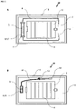
- figure 1 shows a bottom view of a sterile container lid with a control device.
- Figure 10 shows in A the underside 3 of a sterile container lid 1 with a seal (not shown) and a receiving device 2 (sterile filter cover) for sterile filters with openings 4.
- a supply line 8 for the Passage of steam (represented by arrow a) and a transparent window 5 or a magnifying glass for reading support.
- the supply line 8 can be connected to the cover in a fixed or detachable manner and can have a line that is straight or positioned like a snail.
- Below the transparent window 5 there is a control device 6 in which a control strip or a control label can be placed in a chamber 17 .
- the control device 6 has a clip device 7 for introducing the control body.
- B pressed a seal on the underside 3 of the sterile container lid.
- Steam is fed into the control device via the pipeline.
- the supply line 8 is selected in such a way that the steam has to cover a longer distance, as in the case of a cavity product, in order to simulate safe sterilization of the cavity interior.
- a supply line for steam can be dispensed with, particularly when no cavity products are to be sterilized.
- Representation B shows the same sterile container lid 1 as in representation A, has a control device 6 with a data memory 11, which has a camera from the outside via a connection 9 or here, which can be read out via an adapter.
- the data memory (with electronics and battery) is connected to a sensor line 12 in order to measure the temperature via a front temperature sensor 14 .
- the data are stored in the data memory 11 with a time sequence and can be connected via the connection be read out. Alternatively, the reading can also be contactless.
- the sensor may be located in, on, or connected to steam permeable tubing or tubing to simulate the steam sterilizability of ducts in a lumen product.
- the sensor cable 12 lying on the underside 3 of the sterile container lid 1 is fixed here with a sensor cable holder 13 and can also be placed in the sterile container space, in particular to check the sterilization temperature in the immediate vicinity of a sterile item to be sterilized.
- FIG 2 shows control symbols for control labels.
- Representation A shows a circle symbol 15 with a barely legible word 16 (here the word "sterile").
- the color of the symbol is selected here in such a way that both the circle symbol 15 and the word 16 appear very clearly in the event of a successful sterilization process, preferably in another clearly visible color. Alternatively, only the central core of the circle can change color and thus make the word visible.
- a control label is also shown in B as a triangle symbol 15 . The word inside the symbol is hardly or not legible. Only after a successful sterilization does the word 16 "sterile" appear due to a different colored or darker background. Now the word “sterile” is also easy to read.
- panel C shows, as in A , a circle symbol 15 in a faint stain (a sign of non-sterile) and an internationally known "okay” 16 character which may be barely legible or obscured. This representation indicates to the outside that something is not okay. After sterilization, the "okay" symbol and the surrounding circle appear, indicating that everything is "okay", i.e. sterile.
- Representation D shows a control strip that has no or a barely visible background 15 in the non-sterile version. Only after sterilization has been carried out correctly, e.g. B. a barcode and a word "sterile" 16 clearly visible and the barcode can only now be read.
- the upper representations A, B, C and D thus visualize not only a sterilization process through a color change, but at the same time the symbols 15 and the words or signs 16 increase the information content. In this case, instead of a color conversion, a color release can take place and after removal of this layer, the symbols described can become visible. It is then important that the melting of the cover or barrier layer takes place in a controlled manner. It can be the goal that z. B. a 5-minute sterilization time is observed.
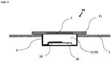
- FIG 3 shows a sectional view of a control device with a simple control strip holder.
- the representation 30 is preferably placed in a sterile container lid 1 so that it can be exchanged.
- the control device can contain a battery, a data memory and electronics as an independent unit and transmit determined pixel or control data to the outside.
- the sterilization medium can easily reach the open space of the control strip holder 26 at least via the side surfaces of the control strip. It is advantageous if the window area is a magnifying glass in order to be able to better observe the control area 18 on the test strip.
- FIG 4 shows a sectional view of a control device for control strips in a sterile container lid 1.
- the representation 40 is a control device 6 in the form of a control chamber 27 which can be opened.
- the chamber 27 is a mountable unit with a cover plate 21, which is fixed in a sterile container lid 1 (z. B. screwed or glued or similar).
- the control device 6 shown can be used alone in a soft packaging or also independently of an outer packaging in a similar configuration. This can be useful if the sterilization in a sterilization chamber is to be examined at different points.
- the sterilization medium z. B. steam is introduced via a pipe opening 8 into the interior 17 of the sterilization chamber 27 .
- a slot or an opening 8 can also be present here.
- the steam can flow into the device space 17 via an opening or the control holder cover itself or has an obstacle course in the form of a snail with at least one entry opening into the control chamber 27 on the side of the chamber.
- the cover plate 21 has a transparent window 5 with or without a magnifying glass function. Through window 5 one can see the spaced control strip and observe its color change after sterilization.
- control unit 40 can be exchanged as a whole unit. Provision can also be made for several control units to be arranged one behind the other and connected to one another with a hose in order to achieve double determination.
- the control strip itself can consist of a filter material in order to absorb melted materials.
- FIG. 5 shows a sectional representation of a control device in connection with a light guide in a sterile container lid 1.
- a control device is also described.
- a light guide 24 with a connection adapter 9 is preferably screwed to a sterile container cover 1 .
- the light guide 24 can be fixed freely in the sterile container space or via a fixation on the cover.
- the cap with the internal temperature-sensitive control surface 18 and a cap space 17 is easy to replace and together with the light guide 24 forms the control device.
- the advantage of this control device is that the color change can be detected in the smallest of spaces and the evaluation can be carried out using a pixel analysis.
- the cap 23 can be constructed in such a way that the vapor first has to be guided through the openings 8 and then over an obstacle or barrier 25 which is located in front of the control surface in order to reach the control surface 18 .
- the upstream obstacle can be a filter material that absorbs the melted material (top layer).
- the device thus corresponds to a Bowie-Dick test device.
- the light guide can be located in a longer hose line or pipeline and this is closed to the outside by a filter element at the ends.
- FIG 6 shows a transparent device with a control strip holder.
- the transparent device is shown here as a cover 60 and is preferably made of a transparent plastic. Alternatively, this device 60 can also be used in a similar form in soft packaging.
- the lid is designed in such a way that a control strip holder 33 is worked out of the lid material or was formed from this material.
- a control strip 32 is preferably inserted laterally. It can be provided that when the control strip is inserted, it is mechanically damaged in order to prevent it being used twice.
- the holder 33 is preferably made of the same or similar material as the cover and could be made of z. B. injection molding or in the 3D process.
- the holder has lateral retaining parts formed in the retaining groove or a retaining spring 19, in order to receive the control strip preferably in a non-positive or positive manner.
- This device 60 can also have lateral obstacles or be connected to them.
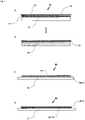
- FIG 7 shows a representation of a control strip with a layer structure.
- the control strip 70 in illustration A consists of different layers.
- the first layer is a transparent protective layer 28. Alternatively, this layer may not be present if the product is to be used in cleaning machines.
- the second layer 29 forms a fusible material.
- a temperature-sensitive indicator layer 35 which can also contain metal crystals for displaying the temperature. This layer reacts with a color change at a defined temperature.
- the above layers 28, 29 and 35 are applied to a substrate 32 such as. B. paper or applied to a solution-stable plastic support with or without a filter paper layer.
- Absorbent carrier materials 32 are advantageous in order to absorb the melted material 29 .
- the representation B shows that the melted Material of the layer 29 flows at a set melting temperature in the carrier material 32, for example via channels or migrates through this material 32 or diffuses.
- Layer 35 can preferably contain test germs or other biomaterial.
- the protective layer is removed and the control strip (also in round form) is brought into contact with an agar layer in a Petri dish. After a defined contact with the agar, the Petri dish is placed in an incubator chamber for several days to observe bacterial growth.
- Representation C shows a control strip 80 with a growth layer 31 for germs which is applied as a surface on the control strip 32 . Temperature indicators 34 can be introduced into this layer in order to carry out a color change when the sterilization temperature is reached.
- test strips are already used sterile, preferably with a protective layer.
- Representation D shows a control strip 90, with a solid culture medium 31 (growth layer or surface) lying over an indicator layer 35 here. Due to the thickness of this growth layer 31 , the introduced steam or the sterilization medium will have a more or less delayed effect, thus ensuring that the sterilization medium is also effective under these conditions.
- the test strips A, B, C and D shown here can be placed in a filter basket or in a sterile container using a holder.
Landscapes
- Health & Medical Sciences (AREA)
- Epidemiology (AREA)
- Life Sciences & Earth Sciences (AREA)
- Animal Behavior & Ethology (AREA)
- General Health & Medical Sciences (AREA)
- Public Health (AREA)
- Veterinary Medicine (AREA)
- Apparatus For Disinfection Or Sterilisation (AREA)
Applications Claiming Priority (1)
| Application Number | Priority Date | Filing Date | Title |
|---|---|---|---|
| DE102021003190.3A DE102021003190A1 (de) | 2021-06-21 | 2021-06-21 | Sterilisationsvorrichtung und Kontrolleinheit |
Publications (1)
| Publication Number | Publication Date |
|---|---|
| EP4108264A1 true EP4108264A1 (fr) | 2022-12-28 |
Family
ID=82067728
Family Applications (1)
| Application Number | Title | Priority Date | Filing Date |
|---|---|---|---|
| EP22000155.6A Pending EP4108264A1 (fr) | 2021-06-21 | 2022-06-14 | Dispositif de stérilisation doté d'un dispositif de commande |
Country Status (2)
| Country | Link |
|---|---|
| EP (1) | EP4108264A1 (fr) |
| DE (1) | DE102021003190A1 (fr) |
Families Citing this family (2)
| Publication number | Priority date | Publication date | Assignee | Title |
|---|---|---|---|---|
| DE202023103401U1 (de) * | 2023-06-20 | 2024-09-25 | Normec Hybeta Gmbh | Prüfkörper für ein medizinisches Reinigungsgerät |
| EP4784323A1 (fr) * | 2023-09-26 | 2026-08-05 | Albert Browne Limited | Indicateur d'efficacité ultrasonore et de nettoyage |
Citations (5)
| Publication number | Priority date | Publication date | Assignee | Title |
|---|---|---|---|---|
| DE102007044703A1 (de) * | 2007-09-19 | 2009-04-02 | Wolfgang Weber | Transportabler Sterilisierbehälter aus Metall oder Hartkunststoff zur Aufnahme von klinischem Sterilgut |
| DE102009000932A1 (de) * | 2009-02-17 | 2010-08-26 | Vereinigte Papierwarenfabriken Gmbh | Prüfvorrichtung für einen Sterilisationsprozess |
| DE102017117624A1 (de) | 2017-08-03 | 2019-02-07 | Aesculap Ag | Modular aufgebauter Deckel für einen Sterilbehälter und Filterabdeckung für einen solchen Deckel |
| WO2020222054A1 (fr) * | 2019-05-02 | 2020-11-05 | 3M Innovative Properties Company | Ensemble de test de stérilisation |
| EP3936160A1 (fr) * | 2020-07-01 | 2022-01-12 | Mesa Laboratories, Inc. | Indicateur de nettoyage |
-
2021
- 2021-06-21 DE DE102021003190.3A patent/DE102021003190A1/de active Pending
-
2022
- 2022-06-14 EP EP22000155.6A patent/EP4108264A1/fr active Pending
Patent Citations (5)
| Publication number | Priority date | Publication date | Assignee | Title |
|---|---|---|---|---|
| DE102007044703A1 (de) * | 2007-09-19 | 2009-04-02 | Wolfgang Weber | Transportabler Sterilisierbehälter aus Metall oder Hartkunststoff zur Aufnahme von klinischem Sterilgut |
| DE102009000932A1 (de) * | 2009-02-17 | 2010-08-26 | Vereinigte Papierwarenfabriken Gmbh | Prüfvorrichtung für einen Sterilisationsprozess |
| DE102017117624A1 (de) | 2017-08-03 | 2019-02-07 | Aesculap Ag | Modular aufgebauter Deckel für einen Sterilbehälter und Filterabdeckung für einen solchen Deckel |
| WO2020222054A1 (fr) * | 2019-05-02 | 2020-11-05 | 3M Innovative Properties Company | Ensemble de test de stérilisation |
| EP3936160A1 (fr) * | 2020-07-01 | 2022-01-12 | Mesa Laboratories, Inc. | Indicateur de nettoyage |
Also Published As
| Publication number | Publication date |
|---|---|
| DE102021003190A1 (de) | 2023-01-05 |
Similar Documents
| Publication | Publication Date | Title |
|---|---|---|
| DE10296927B4 (de) | Vorrichtung zum Beurteilen eines Reinigungsprozesses von Endoskopen | |
| DE102018108325B4 (de) | Sensoraufnahme für einen Bioreaktor sowie Bioreaktor mit Sensoraufnahme und Verfahren zur Vermehrung oder Kultivierung biologischen Materials | |
| DE69833241T2 (de) | Überwachung eines Reinigungsprozesses | |
| DE102009022545B3 (de) | Verpackungsmaschine mit Gas-Konzentrations-Messeinrichtung | |
| EP0466009A1 (fr) | Système de transport pour l'expédition d'échantillons biologiques | |
| DE2152068A1 (de) | Vorrichtung zur Untersuchung der biologischen Wirksamkeit von Kontrollreagenzien | |
| DE102021003190A1 (de) | Sterilisationsvorrichtung und Kontrolleinheit | |
| DE19903506A1 (de) | Verfahren, Gefäß und Vorrichtung zur Überwachung der Stoffwechselaktivität von Zellkulturen in flüssigen Medien | |
| EP2507616A1 (fr) | Dispositif de protection de capteur | |
| DE102014203815B4 (de) | Verfahren zur Weinanalyse und zugehörige Vorrichtung | |
| DE102016101715A1 (de) | Sensoranordnung | |
| DE4032002C2 (de) | In situ Mikroskopsonde und Meßverfahren | |
| EP1468701B1 (fr) | Dispositif de test, en particulier pour évaluer les proprietés de pénétration d'un stérilisant dans des procédés de stérilisation | |
| DE102017124840B3 (de) | Inkubator, Probenbehälter, Set und Verfahren zur Untersuchung eines Probenmaterials | |
| EP2051745A1 (fr) | Dispositif destiné à vérifier les résultats de nettoyage et de désinfection d'instruments de diagnostic et chirurgicaux nettoyés notamment dans des machines à laver automatiques | |
| WO2013110697A1 (fr) | Sonde à réflexion | |
| DE102005021034B4 (de) | Verfahren zur Kultivierung einer Zellkultur in einem automatisierten Zellkultursystem sowie automatisiertes Zellkultursystem | |
| EP1485135B1 (fr) | Procede pour controler une unite de conditionnement de sterilisation quant a son efficacite contre la contamination | |
| EP4260689A1 (fr) | Système pour installations de culture ou de recherche de plantes avec station interchangeable, récipients et ensemble de dispositifs de marquage pour ceux-ci | |
| DE102008034062B4 (de) | Verfahren und Prüfvorrichtung | |
| DE102018209119A1 (de) | Referenzprüfkörper, Verwendung, Prüfkammer und Verfahren | |
| EP1084714A1 (fr) | Dispositif pour essais de stérilisation | |
| DE2614542A1 (de) | Verfahren zur entnahme von reaktionsgut aus unter sterilen bedingungen arbeitenden reaktoren und vorrichtung zu seiner durchfuehrung | |
| DE102007044703A1 (de) | Transportabler Sterilisierbehälter aus Metall oder Hartkunststoff zur Aufnahme von klinischem Sterilgut | |
| EP1925321A1 (fr) | Dispositif pour le nettoyage des instruments chirurgicaux à tige tubulaire et creuse |
Legal Events
| Date | Code | Title | Description |
|---|---|---|---|
| PUAI | Public reference made under article 153(3) epc to a published international application that has entered the european phase |
Free format text: ORIGINAL CODE: 0009012 |
|
| STAA | Information on the status of an ep patent application or granted ep patent |
Free format text: STATUS: REQUEST FOR EXAMINATION WAS MADE |
|
| 17P | Request for examination filed |
Effective date: 20220707 |
|
| AK | Designated contracting states |
Kind code of ref document: A1 Designated state(s): AL AT BE BG CH CY CZ DE DK EE ES FI FR GB GR HR HU IE IS IT LI LT LU LV MC MK MT NL NO PL PT RO RS SE SI SK SM TR |
|
| RBV | Designated contracting states (corrected) |
Designated state(s): AL AT BE BG CH CY CZ DE DK EE ES FI FR GB GR HR HU IE IS IT LI LT LU LV MC MK MT NL NO PL PT RO RS SE SI SK SM TR |
|
| STAA | Information on the status of an ep patent application or granted ep patent |
Free format text: STATUS: EXAMINATION IS IN PROGRESS |
|
| 17Q | First examination report despatched |
Effective date: 20240701 |