EP4108271A1 - Pompe seringue - Google Patents
Pompe seringue Download PDFInfo
- Publication number
- EP4108271A1 EP4108271A1 EP21763658.8A EP21763658A EP4108271A1 EP 4108271 A1 EP4108271 A1 EP 4108271A1 EP 21763658 A EP21763658 A EP 21763658A EP 4108271 A1 EP4108271 A1 EP 4108271A1
- Authority
- EP
- European Patent Office
- Prior art keywords
- flange
- pushing portion
- syringe pump
- syringe
- plunger rod
- Prior art date
- Legal status (The legal status is an assumption and is not a legal conclusion. Google has not performed a legal analysis and makes no representation as to the accuracy of the status listed.)
- Pending
Links
- 230000007246 mechanism Effects 0.000 claims abstract description 36
- 230000005540 biological transmission Effects 0.000 claims description 16
- 239000003814 drug Substances 0.000 description 5
- 239000007788 liquid Substances 0.000 description 5
- 230000002093 peripheral effect Effects 0.000 description 2
- 239000004743 Polypropylene Substances 0.000 description 1
- 230000008859 change Effects 0.000 description 1
- 230000007423 decrease Effects 0.000 description 1
- 230000000694 effects Effects 0.000 description 1
- 239000010687 lubricating oil Substances 0.000 description 1
- 238000000034 method Methods 0.000 description 1
- 230000004048 modification Effects 0.000 description 1
- 238000012986 modification Methods 0.000 description 1
- -1 polypropylene Polymers 0.000 description 1
- 229920001155 polypropylene Polymers 0.000 description 1
- 230000009467 reduction Effects 0.000 description 1
- 239000011347 resin Substances 0.000 description 1
- 229920005989 resin Polymers 0.000 description 1
- 230000004044 response Effects 0.000 description 1
- 229920002545 silicone oil Polymers 0.000 description 1
Images




Classifications
-
- A—HUMAN NECESSITIES
- A61—MEDICAL OR VETERINARY SCIENCE; HYGIENE
- A61M—DEVICES FOR INTRODUCING MEDIA INTO, OR ONTO, THE BODY; DEVICES FOR TRANSDUCING BODY MEDIA OR FOR TAKING MEDIA FROM THE BODY; DEVICES FOR PRODUCING OR ENDING SLEEP OR STUPOR
- A61M5/00—Devices for bringing media into the body in a subcutaneous, intra-vascular or intramuscular way; Accessories therefor, e.g. filling or cleaning devices, arm-rests
- A61M5/14—Infusion devices, e.g. infusing by gravity; Blood infusion; Accessories therefor
- A61M5/142—Pressure infusion, e.g. using pumps
- A61M5/145—Pressure infusion, e.g. using pumps using pressurised reservoirs, e.g. pressurised by means of pistons
- A61M5/1452—Pressure infusion, e.g. using pumps using pressurised reservoirs, e.g. pressurised by means of pistons pressurised by means of pistons
- A61M5/1456—Pressure infusion, e.g. using pumps using pressurised reservoirs, e.g. pressurised by means of pistons pressurised by means of pistons with a replaceable reservoir comprising a piston rod to be moved into the reservoir, e.g. the piston rod is part of the removable reservoir
-
- A—HUMAN NECESSITIES
- A61—MEDICAL OR VETERINARY SCIENCE; HYGIENE
- A61M—DEVICES FOR INTRODUCING MEDIA INTO, OR ONTO, THE BODY; DEVICES FOR TRANSDUCING BODY MEDIA OR FOR TAKING MEDIA FROM THE BODY; DEVICES FOR PRODUCING OR ENDING SLEEP OR STUPOR
- A61M5/00—Devices for bringing media into the body in a subcutaneous, intra-vascular or intramuscular way; Accessories therefor, e.g. filling or cleaning devices, arm-rests
- A61M5/14—Infusion devices, e.g. infusing by gravity; Blood infusion; Accessories therefor
- A61M5/142—Pressure infusion, e.g. using pumps
- A61M5/145—Pressure infusion, e.g. using pumps using pressurised reservoirs, e.g. pressurised by means of pistons
- A61M5/1452—Pressure infusion, e.g. using pumps using pressurised reservoirs, e.g. pressurised by means of pistons pressurised by means of pistons
- A61M5/1458—Means for capture of the plunger flange
Definitions
- the present disclosure relates to a syringe pump.
- a syringe pump is used to administer an accurate amount of liquid medicine from a syringe.
- PTL 1 Japanese Patent Laying-Open No. 2017-51548
- PTL 2 Japanese Patent Laying-Open No. 2019-10502 disclose a technique for suppressing a siphoning phenomenon which causes the liquid medicine in the syringe to be administered without being controlled by the syringe pump.
- the syringe pump according to the present disclosure is applied to a syringe that includes a barrel and a plunger rod which is fitted inside the barrel.
- a flange is provided at a rear end of the plunger rod.
- the syringe pump includes a clamping mechanism which clamps and fixes the flange of the plunger rod in a thickness direction of the flange.
- the clamping mechanism includes a pushing portion which includes a pressing face facing a rear end face of the flange, and a gripping portion which is movable in the thickness direction and connected to the pushing portion so as to form a gap with the pressing face in the thickness direction, and is configured to work in cooperation with the pushing portion so as to fix the flange.
- the pushing portion includes a locking mechanism which locks the movement of the gripping portion in a direction away from the pressing face with the flange being fixed.
- the syringe pump further includes an operation member for operating the gripping portion.
- the pushing portion further includes a transmission mechanism which transmits an operation force from the operation member to the gripping portion, and a casing which forms the pressing face and houses the transmission mechanism, and the locking mechanism is formed between the transmission mechanism and the casing.
- the locking mechanism includes a tapered face formed on the casing, and an abutment member provided on the transmission mechanism and configured to abut against the tapered face.
- the gripping portion includes a finger member rotatable about an axis in the thickness direction with respect to the pushing portion
- the transmission mechanism includes a rotating member which rotates together with the finger member, and the abutment member is formed on the rotating member.
- the pushing portion further includes a bias member configured to bias the transmission mechanism so as to draw the gripping portion toward the pressing face.
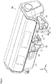
- Figs. 1 to 3 each illustrate a syringe pump according to an embodiment of the present disclosure.
- the syringe pump 100 illustrated in each of Figs. 1 to 3 is viewed from different directions.
- the X-axis, the Y-axis and the Z-axis illustrated in Figs. 1 to 3 are orthogonal to each other.
- the syringe pump 100 includes a main body 110, a syringe mounting member 120, a barrel flange retainer 130, a slide shaft 140, a pushing portion 150, a gripping portion 160, and an operation member 170.
- the main body 110 is provided with a drive unit and a control unit that controls the drive unit.
- the drive unit includes a motor that drives the slide shaft 140 and a reduction gear that is connected to the motor.
- a syringe to be described later is mounted on the syringe mounting member 120.
- the syringe mounting member 120 is provided at one side of the main body 110.
- the syringe mounting member 120 includes a concave member 121 and a syringe clamp 122.
- the concave member 121 has a concave face which curves into an arc shape in the cross section, and is configured to extend in the central axis direction of the arc.
- the syringe clamp 122 is provided to face the concave member 121 and is configured to be brought into contact or out of contact with the concave member 121.
- the syringe clamp 122 has a concave face which is provided at the side facing the concave member 121 and is configured to curve into an arc shape in the opposite direction to the concave face of the concave member 121.
- the concave face of the concave member 121 and the concave face of the syringe clamp 122 clamp the barrel therebetween, whereby the syringe is fixed in the syringe mounting member 120.
- the barrel flange retainer 130 is provided at an end of the syringe mounting member 120. After the syringe is installed in the syringe pump, the barrel flange retainer 130 abuts against a flange (barrel flange) provided at the end of the barrel.
- the slide shaft 140 is connected to the drive unit of the main body 110, and the other end thereof is connected to the pushing portion 150.
- the slide shaft 140 is slidable in the axial direction of the slide shaft 140.
- the axial direction of the slide shaft 140 is substantially parallel to the extending direction of the concave member 121.
- the configuration of the pushing portion 150 will be described later.
- the pushing portion 150 and the gripping portion 160 constitute a "clamping mechanism” that clamps and fixes the flange of the plunger rod of the syringe in the thickness direction of the flange (the Z-axis direction).
- the grip member 160 includes a pair of finger members 161 and 162. Each of the pair of finger members 161 and 162 is connected to the operation member 170 with the pushing portion 150 interposed therebetween.
- each of the pair of finger members 161 and 162 are rotated so as to force the distal ends thereof to separate from each other. At this time, the pair of finger members 161 and 162 slide away from the pushing portion 150 in the Z-axis direction. This state is called the "open state" of the operation member 170.
- the flange of the plunger rod is arranged between the pushing portion 150 and the gripping portion 160, and then the operation member 170 is returned to the "closed state", whereby the flange of the plunger rod is clamped and fixed in the thickness direction (the Z-axis direction).
- the pushing portion 150 and the gripping portion 160 function as a “clamping mechanism” that clamps and fixes the flange of the plunger rod in the thickness direction.
- the pushing portion 150 and the gripping portion 160 are driven by the drive unit of the main body 110 to slide together with the slide shaft 140 in the axial direction (the Z-axis direction) of the slide shaft 140.
- the axial direction of the slide shaft 140 is identical to the axial direction of the plunger rod.
- the drive unit of the main body 110 and the slide shaft 140 function as a "moving mechanism” that moves the “clamping mechanism” along the axial direction of the plunger rod.
- Fig. 4 is a perspective view illustrating an appearance of a syringe to be installed in the syringe pump 100.
- the syringe 200 includes a barrel 210 and a plunger rod 220.
- the barrel 210 has a cylindrical housing member 211 that houses a liquid medicine therein.
- a liquid medicine inlet/outlet 212 is provided at a front end of the barrel 210.
- An opening is provided at a rear end of the barrel 210, and a flange 213 is formed around the opening.
- the barrel 210 is made of a transparent or translucent resin such as polypropylene.
- Lubricating oil such as silicone oil may be applied to an inner peripheral surface of the barrel 210.
- a gasket (not shown) is provided at the distal end of the plunger rod 220, and is configured to be in slide contact with the inner peripheral surface of the barrel 210.
- a flange 221 is provided at the rear end of the plunger rod 220.
- the plunger rod 220 includes a shaft 222 that connects the gasket and the flange 221.
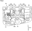
- Fig. 5 is a perspective view illustrating an internal structure of the pushing portion 150
- Fig. 6 is a view illustrating a transmission mechanism that transmits an operation force from the operation member 170 to the gripping portion 160
- Fig. 7 is a cross-sectional view of the pushing portion 150 cut along the Y-axis direction.
- the pushing portion 150 includes a first member 151, a second member 152, a third member 153, a bias member 154, a casing 155, a bias member 156, and a rotating member 157.
- the casing 155 houses the first member 151, the second member 152, the third member 153, the bias member 154, the bias member 156, and the rotating member 157.
- the operation member 170 is firstly rotated. Thereby, the distal ends of the pair of finger members 161 and 162 are separated from each other.
- the rotational operation force generated by the operation member 170 is transmitted to the first member 151 through the rotating member 157.
- the first member 151 rotates in the direction indicated by an arrow DR1 in Fig. 6 .
- the second member 152 which is engaged with the first member 151 rotates in the direction indicated by an arrow DR2.
- the teeth provided on a left part of the third member 153 mesh with the teeth of the second member 152, and the teeth provided on a right part of the third member 153 mesh with the teeth of the first member 151. Due to the rotation of the first member 151 and the second member 152, the left part rotates in the direction indicated by an arrow DR31, and the right part of the third member 153 rotates in the direction indicated by an arrow DR32.
- the left part of the third member 153 is coupled to the finger member 161
- the right part of the third member 153 is coupled to the finger member 162.
- the pair of finger members 161 and 162 rotate in the direction indicated by an arrow DR161 and in the direction indicated by an arrow DR162, respectively. Thereby, the distal ends of the pair of finger members 161 and 162 are separated from each other, achieving the "open state".
- the flange 221 of the plunger rod 220 is arranged between the pair of finger members 161, 162 and the casing 155. Then, by rotating the operation member 170 in the reverse direction, the distal ends of the pair of finger members 161 and 162 become close to each other. In other words, by rotating the first member 151, the second member 152 and the third member 153 in a direction opposite to the direction of switching the operation member 170 to the "open state", the distal ends of the pair of finger members 161 and 162 become close to each other, achieving the "closed state".
- the first member 151, the second member 152, and the third member 153 constitute a "transmission mechanism" that transmits an operation force from the operation member 170 to the gripping portion 160.
- the third member 153 includes a protrusion 153A (abutment member) that protrudes toward the inner surface of the casing 155, and a connection member 153B that connects the left part and the right part of the third member 153.
- the casing 155 is provided with a protrusion 155A that protrudes toward the third member 153.
- the protrusion 153A of the third member 153 comes into contact with the protrusion 155A of the casing 155, thereby preventing the third member 153 from moving in the Z-axis direction (the direction away from the operation member 170).
- a tapered face 155B is formed at the tip of the protrusion 155A, and the tapered face 155B is configured to change a protruding amount of the protrusion 155A in the circumferential direction of the protrusion 155A.
- the casing 155 has a pressing face 155C facing the pair of finger members 161 and 162.
- the bias member 154 biases the third member 153 and the gripping portion 160 toward the operation member 170 (in the +Z direction).
- the bias member 156 biases the first member 151 away from the operation member 170 (in the -Z direction).
- the first member 151, the second member 152, and the third member 153 are supported on the casing 155 with the bias members 154 and 156 interposed therebetween in the Z-axis direction.
- the protrusion 153A of the third member 153 is in contact with the protrusion 155A of the casing 155 at the largest protruding amount (the largest height). Therefore, in the "closed state”, the third member 153 and the finger members 161 and 162 are prevented from moving in the -Z direction (toward the upper side of Fig. 7 ). As a result, the finger members 161 and 162 are maintained at a position close to the pressing face 155C.
- the tapered face 155B is formed such a manner that the height of the protrusion 155A of the casing 155 in contact with the protrusion 153A of the third member 153 gradually decreases as the left part and the right part of the third member 153 rotate in the direction indicated by the arrow DR31 and the direction indicated by the arrow DR32, respectively.
- the third member 153 and the finger members 161 and 162 become movable in the -Z direction (toward the upper side of Fig. 7 ) as the state is switched from the "closed state" to the "open state".
- the finger members 161 and 162 are slid to a position separated from the pressing face 155C, which allows the flange 221 of the plunger rod 220 to be arranged between the finger members 161 and 162 and the pressing face 155C.
- the flange 221 of the plunger rod 220 can be clamped and fixed in the thickness direction of the flange 221.
- the finger members 161 and 162 are slid to a position separated from the pressing face 155C.
- the slide amount changes in response to the opening angle of the finger members 161 and 162, in other words, the rotation angle of the operation member 170. Therefore, even when the thickness of the flange 221 varies depending on the size of the syringe 200, it is possible to fix the flange 221 by appropriately adjusting the gap between the pressing face 155C and the finger members 161 and 162.
- the pair of finger members 161 and 162 are biased in the +Z direction by a biasing force from the bias member 154.
- a force in the -Z direction which is larger than the biasing force from the bias member 154 in the +Z direction may act on the plunger rod 220.
- the protrusion 153A of the third member 153 and the protrusion 155A of the casing 155 are brought into contact with each other, whereby the finger members 161 and 162 (the gripping portion 160) are prevented from moving in the -Z direction (toward the upper side of Fig. 7 ), which makes it possible to prevent the plunger rod 220 from moving unintendedly even under a negative pressure condition.
- the protrusion 153A of the third member 153 and the protrusion 155A of the casing 155 function as a "locking mechanism" that locks the movement of the gripping portion 160 in the Z-axis direction after the flange 221 is fixed.
- the syringe pump 100 is applied to the syringe 200 that includes the barrel 210 and the plunger rod 220 which is fitted inside the barrel 210.
- the flange 221 is provided at a rear end of the plunger rod 220.
- the syringe pump 100 includes the pushing portion 150 and the holding portion 160 (constituting a clamping mechanism) which clamp and fix the flange 221 of the plunger rod 220 in the thickness direction of the flange 221.
- the pushing portion 150 includes the pressing face 155C facing a rear end face of the flange 221.
- the gripping portion 160 is movable in the thickness direction of the flange 221 (the Z-axis direction) and connected to the pushing portion 150 so as to form a gap with the pressing face 155C in the Z-axis direction, and is configured to work in cooperation with the pushing portion 150 so as to fix the flange 221.
- the pushing portion 150 locks the movement of the gripping portion 160 in a direction away from the pressing face 155C with the flange 221 being fixed.
- the pushing portion 150 includes the first member 151, the second member 152 and the third member 153 (constituting a transmission mechanism) for transmitting an operation force from the operation member 170 to the gripping portion 160, and the casing 155 which forms the pressing face 155C and houses the first member 151, the second member 152 and the third member 153.
- the movement of the gripping portion 160 in the Z-axis direction is locked when the protrusion 153A (an abutment member) provided on the third member 153 abuts against the tapered face 155B formed inside the casing 155.
- the gripping portion 160 includes a pair of finger members 161 and 162 rotatable about the Z axis with respect to the pushing portion 150.
- the third member 153 (a rotating member) rotates together with the finger members 161 and 162.
- the bias member 154 biases the third member 153 in the +Z direction to draw the gripping portion 160 toward the pressing face 155C.
- 100 syringe pump; 110: main body; 120: syringe mounting member; 121: concave member; 122: syringe clamp; 130: barrel flange retainer; 140: slide shaft; 150: pushing portion; 151: first member; 152: second member; 153: third member; 153A: protrusion; 153B: connection member; 154: bias member; 155: casing; 155A: protrusion; 155B: tapered face; 155C: pressing face; 156: bias member; 157: rotating member; 160: gripping portion; 161, 162: finger member; 170: operation member; 200: syringe; 210: barrel; 211: housing member; 212: liquid medicine inlet/outlet; 213: flange; 220: plunger rod; 221: flange; 222: shaft
Landscapes
- Health & Medical Sciences (AREA)
- Vascular Medicine (AREA)
- Engineering & Computer Science (AREA)
- Anesthesiology (AREA)
- Biomedical Technology (AREA)
- Heart & Thoracic Surgery (AREA)
- Hematology (AREA)
- Life Sciences & Earth Sciences (AREA)
- Animal Behavior & Ethology (AREA)
- General Health & Medical Sciences (AREA)
- Public Health (AREA)
- Veterinary Medicine (AREA)
- Infusion, Injection, And Reservoir Apparatuses (AREA)
Applications Claiming Priority (2)
| Application Number | Priority Date | Filing Date | Title |
|---|---|---|---|
| JP2020038011 | 2020-03-05 | ||
| PCT/JP2021/008331 WO2021177389A1 (fr) | 2020-03-05 | 2021-03-04 | Pompe seringue |
Publications (2)
| Publication Number | Publication Date |
|---|---|
| EP4108271A1 true EP4108271A1 (fr) | 2022-12-28 |
| EP4108271A4 EP4108271A4 (fr) | 2024-03-13 |
Family
ID=77612655
Family Applications (1)
| Application Number | Title | Priority Date | Filing Date |
|---|---|---|---|
| EP21763658.8A Pending EP4108271A4 (fr) | 2020-03-05 | 2021-03-04 | Pompe seringue |
Country Status (3)
| Country | Link |
|---|---|
| EP (1) | EP4108271A4 (fr) |
| JP (1) | JP7586166B2 (fr) |
| WO (1) | WO2021177389A1 (fr) |
Cited By (1)
| Publication number | Priority date | Publication date | Assignee | Title |
|---|---|---|---|---|
| WO2025240413A1 (fr) * | 2024-05-13 | 2025-11-20 | Deka Products Limited Partnership | Appareils, systèmes et procédés de pompe à seringue |
Family Cites Families (8)
| Publication number | Priority date | Publication date | Assignee | Title |
|---|---|---|---|---|
| US6428509B1 (en) | 1999-07-29 | 2002-08-06 | Alaris Medical Systems, Inc. | Syringe plunger driver system and method |
| FR2880809B1 (fr) | 2005-01-17 | 2007-02-23 | Fresenius Vial Soc Par Actions | Dispositif de retenue pour bloquer la tete de piston d'une seringue sur le poussoir d'un pousse seringue |
| JP2007236858A (ja) | 2006-03-13 | 2007-09-20 | Japan Servo Co Ltd | 輸液装置 |
| JP4833732B2 (ja) * | 2006-05-16 | 2011-12-07 | テルモ株式会社 | シリンジポンプ |
| JP5231872B2 (ja) * | 2008-06-03 | 2013-07-10 | テルモ株式会社 | シリンジポンプ |
| WO2010041592A1 (fr) * | 2008-10-06 | 2010-04-15 | テルモ株式会社 | Pompe de seringue |
| JP6569412B2 (ja) | 2015-09-11 | 2019-09-04 | ニプロ株式会社 | 薬剤投与具 |
| JP7040273B2 (ja) | 2017-06-29 | 2022-03-23 | ニプロ株式会社 | シリンジポンプ |
-
2021
- 2021-03-04 EP EP21763658.8A patent/EP4108271A4/fr active Pending
- 2021-03-04 WO PCT/JP2021/008331 patent/WO2021177389A1/fr not_active Ceased
- 2021-03-04 JP JP2022504448A patent/JP7586166B2/ja active Active
Cited By (1)
| Publication number | Priority date | Publication date | Assignee | Title |
|---|---|---|---|---|
| WO2025240413A1 (fr) * | 2024-05-13 | 2025-11-20 | Deka Products Limited Partnership | Appareils, systèmes et procédés de pompe à seringue |
Also Published As
| Publication number | Publication date |
|---|---|
| WO2021177389A1 (fr) | 2021-09-10 |
| EP4108271A4 (fr) | 2024-03-13 |
| JP7586166B2 (ja) | 2024-11-19 |
| JPWO2021177389A1 (fr) | 2021-09-10 |
Similar Documents
| Publication | Publication Date | Title |
|---|---|---|
| EP1978256B1 (fr) | Pompe a galets | |
| US6997079B2 (en) | Gear mechanism with an idler gear, a gear mechanism with a device for eliminating backlash between gears, and a motor driving mechanism | |
| CN103153156B (zh) | 内窥镜的弯曲操作装置、内窥镜 | |
| JP4370069B2 (ja) | シリンジ・プランジャ・ドライバのシステムおよび方法 | |
| CN112807526B (zh) | 注射泵 | |
| KR960033879A (ko) | 회전핸들로 로터리부재를 제어하는 기구 및 그 기구가 구비된 시이트 | |
| EP4108271A1 (fr) | Pompe seringue | |
| CN108027163B (zh) | 导风板装置 | |
| JP4772340B2 (ja) | 自転車用変速機のための改良されたアクチュエータ・デバイス | |
| CN112807524B (zh) | 注射泵 | |
| JP2023027907A (ja) | シリンジポンプ | |
| JP6447089B2 (ja) | アタッチメント | |
| US20240374828A1 (en) | Syringe Positioning Assembly and Syringe Pump | |
| CN211486025U (zh) | 注射泵的泵体装置及注射泵 | |
| CN111685878A (zh) | 持针器的卡口结构及持针器控制组件 | |
| JP5547666B2 (ja) | ピペット装置 | |
| JP2019010502A (ja) | シリンジポンプ | |
| CN211486023U (zh) | 注射泵 | |
| CN212411908U (zh) | 一种多旋钮转向柱开关 | |
| CN218220735U (zh) | 一种夹紧装置及注射泵 | |
| CN112807527A (zh) | 注射泵的泵体装置及注射泵 | |
| JP4831412B2 (ja) | シリンジポンプ | |
| US20180164568A1 (en) | Microscope with friction drives | |
| CN213116948U (zh) | 一种锁紧装置 | |
| CN219764162U (zh) | 注射泵以及注射装置 |
Legal Events
| Date | Code | Title | Description |
|---|---|---|---|
| STAA | Information on the status of an ep patent application or granted ep patent |
Free format text: STATUS: THE INTERNATIONAL PUBLICATION HAS BEEN MADE |
|
| PUAI | Public reference made under article 153(3) epc to a published international application that has entered the european phase |
Free format text: ORIGINAL CODE: 0009012 |
|
| STAA | Information on the status of an ep patent application or granted ep patent |
Free format text: STATUS: REQUEST FOR EXAMINATION WAS MADE |
|
| 17P | Request for examination filed |
Effective date: 20220923 |
|
| AK | Designated contracting states |
Kind code of ref document: A1 Designated state(s): AL AT BE BG CH CY CZ DE DK EE ES FI FR GB GR HR HU IE IS IT LI LT LU LV MC MK MT NL NO PL PT RO RS SE SI SK SM TR |
|
| DAV | Request for validation of the european patent (deleted) | ||
| DAX | Request for extension of the european patent (deleted) | ||
| A4 | Supplementary search report drawn up and despatched |
Effective date: 20240208 |
|
| RIC1 | Information provided on ipc code assigned before grant |
Ipc: A61M 5/315 20060101ALI20240202BHEP Ipc: A61M 5/145 20060101AFI20240202BHEP |