EP4108305A1 - Appareil de simulation de mouvement - Google Patents
Appareil de simulation de mouvement Download PDFInfo
- Publication number
- EP4108305A1 EP4108305A1 EP22172022.0A EP22172022A EP4108305A1 EP 4108305 A1 EP4108305 A1 EP 4108305A1 EP 22172022 A EP22172022 A EP 22172022A EP 4108305 A1 EP4108305 A1 EP 4108305A1
- Authority
- EP
- European Patent Office
- Prior art keywords
- pivot axis
- support base
- pivot
- simulating apparatus
- coupling part
- Prior art date
- Legal status (The legal status is an assumption and is not a legal conclusion. Google has not performed a legal analysis and makes no representation as to the accuracy of the status listed.)
- Granted
Links
Images



Classifications
-
- G—PHYSICS
- G09—EDUCATION; CRYPTOGRAPHY; DISPLAY; ADVERTISING; SEALS
- G09B—EDUCATIONAL OR DEMONSTRATION APPLIANCES; APPLIANCES FOR TEACHING, OR COMMUNICATING WITH, THE BLIND, DEAF OR MUTE; MODELS; PLANETARIA; GLOBES; MAPS; DIAGRAMS
- G09B9/00—Simulators for teaching or training purposes
-
- A—HUMAN NECESSITIES
- A63—SPORTS; GAMES; AMUSEMENTS
- A63G—MERRY-GO-ROUNDS; SWINGS; ROCKING-HORSES; CHUTES; SWITCHBACKS; SIMILAR DEVICES FOR PUBLIC AMUSEMENT
- A63G31/00—Amusement arrangements
- A63G31/02—Amusement arrangements with moving substructures
-
- A—HUMAN NECESSITIES
- A63—SPORTS; GAMES; AMUSEMENTS
- A63G—MERRY-GO-ROUNDS; SWINGS; ROCKING-HORSES; CHUTES; SWITCHBACKS; SIMILAR DEVICES FOR PUBLIC AMUSEMENT
- A63G31/00—Amusement arrangements
- A63G31/16—Amusement arrangements creating illusions of travel
Definitions
- the present invention relates to motion simulating apparatuses that can carry at least one occupant and create the feeling of being in a real motion environment.
- Motion simulators may be typically used as amusement or training equipment.
- a motion simulator includes a plurality of actuators that are respectively disposed at different locations and along different axes of movements so as to be able to simulate motions along different axes.
- the conventional motion simulators are usually complex in construction and have relatively high manufacturing costs.
- the present application describes a motion simulating apparatus that can address at least the foregoing issues.
- a motion simulating apparatus described herein includes a support base, a coupling part, an occupant platform adapted to carry one or more occupant, and two linear actuators.
- the coupling part is pivotally connected to the support base about a first pivot axis.
- the occupant platform is disposed above the support base and is pivotally connected to the coupling part about a second pivot axis, the first pivot axis being substantially orthogonal to the second pivot axis.
- the two linear actuators are respectively disposed at two opposite sides of the second pivot axis, wherein the two linear actuators are respectively connected pivotally to the support base and are respectively connected pivotally to the occupant platform at the two opposite sides of the second pivot axis.
- a motion simulating apparatus described herein includes a support base, a coupling part, an occupant platform adapted to carry one or more occupants, and an actuating system.
- the coupling part is pivotally connected to the support base about a first pivot axis.
- the occupant platform is disposed above the support base and is pivotally connected to the coupling part about a second pivot axis, the first pivot axis being substantially orthogonal to the second pivot axis.
- the actuating system is connected with the occupant platform, and is operable to cause the occupant platform to rotate about the first pivot axis and the second pivot axis.
- FIG. 1 is a perspective view illustrating an embodiment of a motion simulating apparatus 100.
- FIG. 2 is a side view illustrating the motion simulating apparatus 100.
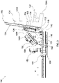
- FIG. 3 is an enlarged view illustrating a portion of the motion simulating apparatus 100 shown in FIG. 2 .
- FIG. 4 is a front view illustrating a portion of the motion simulating apparatus 100.
- FIG. 5 is a rear view illustrating a portion of the motion simulating apparatus 100.
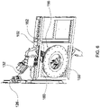
- FIG. 6 is a perspective view illustrating a bottom portion of the motion simulating apparatus 100.
- the motion simulating apparatus 100 can carry occupants or passengers and generate motions in different directions, which is suitable for applications such as simulating platforms or amusement equipment.
- the motion simulating apparatus 100 can include a support base 102, a coupling part 104, an occupant platform 106 and an actuating system 108.
- the support base 102 can extend generally horizontally, and can provide support for the coupling part 104, the occupant platform 106 and the actuating system 108. According to an example of construction, the support base 102 can include a plate structure.
- the coupling part 104 is pivotally connected to the support base 102 about a pivot axis 110, whereby the coupling part 104 can rotate about the pivot axis 110 relative to the support base 102.
- the pivot axis 110 can be a substantially horizontal axis.
- the coupling part 104 can include a frame portion 112, and two extensions 114 fixedly connected with the frame portion 112.
- the coupling part 104 including the frame portion 112 and the two extensions 114 may be integrally formed as a single part, or may be assembled by attaching the two extensions 114 to the frame portion 112 via fasteners.
- the frame portion 112 is adapted to couple to the occupant platform 106, and the two extensions 114 can protrude at an underside of the frame portion 112 and respectively connect pivotally to the support base 102 about the pivot axis 110.
- the frame portion 112 may be generally shaped as a triangle or an isosceles trapezoid, and the two extensions 114 can respectively protrude from two corners of the frame portion 112 at the underside thereof.
- the support base 102 may further include a support frame 116, and the coupling part 104 can include two brackets 118 that are respectively connected with the support frame 116 via two cushioning parts 120.
- the support frame 116 can be exemplarily fixed on the support base 102.
- the cushioning parts 120 may include, without limitation, springs, hydraulic cylinders, pneumatic cylinders, and the like.
- the cushioning parts 120 can provide cushioning support for the coupling part 104.
- the occupant platform 106 is disposed above the support base 102, and is adapted to carry one or more occupants.
- the occupant platform 106 can be pivotally connected to the coupling part 104 about a pivot axis 122, whereby the occupant platform 106 can rotate about the pivot axis 122 relative to the coupling part 104 and the support base 102.
- the pivot axis 110 can be substantially orthogonal to the pivot axis 122, and can be located at an underside of the pivot axis 122.
- the occupant platform 106 can include at least one seat 124 and a seat support frame 126.
- the seat 124 is schematically shown in FIGS.
- the seat 124 can be fixedly connected with the seat support frame 126, and can include a seat portion 124A and a backrest portion 124B that define at least partially a seating space for an occupant.
- the seat support frame 126 can be fixedly connected with a plurality of seats 124 disposed in a row, and an occupant can sit on any of the seats 124 with the feet hanging above a ground.
- the seat support frame 126 can include one or more support bars and/or one or more plates assembled together.
- the seat support frame 126 may be fixedly connected with the backrest portion 124B of each seat 124, and may be pivotally connected to the coupling part 104 about the pivot axis 122 at a rear of the seats 124.
- the seat support frame 126 can be pivotally connected to the frame portion 112 of the coupling part 104 via a bearing 130 at a pivot connecting location 128, the bearing 130 defining the pivot axis 122.
- the bearing 130 may include, without limitation, a ball bearing, a cylinder bearing, and the like.
- the bearing 130 can be disposed at a middle location of the seat support frame 126, and most of the bearing 130 can be arranged above the support frame 116 and the cushioning parts 120. As shown in FIGS. 1-5 , the coupling part 104 and the seat support frame 126 can extend along substantially parallel planes for a compact assembly.
- the actuating system 108 is connected with the occupant platform 106, and is operable to drive the occupant platform 106 to rotate about the pivot axes 110 and 122. More specifically, the actuating system 108 can include at least one linear actuator 132 connected with the occupant platform 106, the linear actuator 132 being operable to drive the occupant platform 106 to rotate relative to the support base 102.
- the linear actuator 132 may include, e.g., an electric cylinder. However, it will be appreciated that the linear actuator 132 may be of any types, which can include, without limitation, pneumatic cylinders and hydraulic cylinders.
- the actuating system 108 can include two linear actuators 132 that are respectively connected pivotally to the support base 102 and are respectively connected pivotally to the occupant platform 106 at two opposite sides of the pivot axis 122.
- One or both of the two linear actuators 132 may apply a force on the occupant platform 106 so as to generate a torque adapted to cause the occupant platform 106 to rotate about the pivot axis 110 and/or the pivot axis 122.
- the force exerted by the two linear actuators 132 on the occupant platform 106 may be able to generate a torque about each of the two pivot axes 110 and 122, and the torque amount may be modified by controlling the course of each of the two linear actuators 132 to cause the occupant platform 106 to rotate about the pivot axis 110 and/or the pivot axis 122.
- the two linear actuators 132 are respectively connected pivotally to the occupant platform 106 at two pivot connecting locations 134, and are respectively connected pivotally to the support base 102 at two pivot connecting locations 136.
- the pivot connecting location 128 of the bearing 130 is at a height H1 relative to the support base 102, which can be between a height H2 of the pivot connecting locations 134 relative to the support base 102 and a height H3 of the pivot connecting locations 136 relative to the support base 102.
- the two linear actuators 132 can be symmetrically disposed at two opposite sides of the pivot axis 122 so that the pivot axis 122 is substantially equidistant to the two pivot connecting locations 134 and is also substantially equidistant to the two pivot connecting locations 136.
- each of the two linear actuators 132 can include a barrel 132A and a sliding rod 132B slidably connected with each other, the barrel 132A being pivotally connected to the support base 102 at the pivot connecting location 136, and the sliding rod 132B being pivotally connected to the occupant platform 106 at the pivot connecting location 134.
- the barrel 132A can be pivotally connected to a pivot mount 138 that is fixedly connected with the support base 102, wherein the pivot mount 138 is disposed at a rear of the support frame 116 so that the support frame 116 is located between the coupling part 104 and the pivot mount 138 along a front-to-rear axis X of the support base 102. Accordingly, the two linear actuators 132 can be tilted an angle relative to the pivot axis 122. According to a symmetrical arrangement, the two linear actuators 132 can extend substantially parallel to each other between the pivot connecting locations 134 and the pivot connecting locations 136, and can respectively move along two parallel vertical planes.
- the two linear actuators 132 are not limited to the aforementioned arrangement. According to another example of construction, the two linear actuators 132 may be symmetrically disposed at two opposite sides of the pivot axis 122 but may not extend parallel to each other between the pivot connecting locations 134 and the pivot connecting locations 136. More specifically, the two linear actuators 132 may be disposed so that the pivot axis 122 is substantially equidistant to the two pivot connecting locations 134 by a first distance, and substantially equidistant to the two pivot connecting locations 136 by a second distance that differs from the first distance.
- the two linear actuators 132 may be disposed equally distant at two opposite sides of the pivot axis 122 but not according to a symmetric arrangement, and the occupant platform 106 can be driven to rotate about the pivot axis 110 and/or the pivot axis 122 by controllably imparting a differential course between the two linear actuators 132.
- the two linear actuators 132 thus may be disposed at two opposite sides of the pivot axis 122 according to any suitable symmetric or asymmetric arrangements for driving the occupant platform 106 to rotate about the pivot axis 110 and/or the pivot axis 122.
- the pivot axis 110 can be a pitch axis
- the pivot axis 122 can be a roll axis
- the two linear actuators 132 are operable to cause the occupant platform 106 to rotate about the pivot axis 110 and/or to rotate about the pivot axis 122 for simulating pitch and/or roll motions.
- the two linear actuators 132 can be operated to generate synchronous and identical courses to cause the occupant platform 106 and the coupling part 104 to pitch up and down about the pivot axis 110 relative to the support base 102, and the two linear actuators 132 can be operated to generate different courses to cause the occupant platform 106 to rotate about the pivot axis 122 to the left and right side relative to the support base 102 and the coupling part 104.
- the actuating system 108 can have a simple construction capable of simulating pitch and roll motions with two linear actuators 132. Examples of applications for the motion simulating apparatus 100 described herein may include, without limitation, flight simulators.
- the actuating system 108 is not limited to the aforementioned configuration.
- a variant construction of the actuating system 108 can include an electric motor, which may be additionally provided in the actuating system 108 or substitute for one of the two linear actuators 132, wherein the electric motor is connected with the occupant platform 106 and is operable to drive the occupant platform 106 to rotate about the pivot axis 122.
- the motion simulating apparatus 100 can further include a bottom part 150 and a motor 152.
- the bottom part 150 can be disposed below the support base 102, which can be pivotally connected to the bottom part 150 about a pivot axis 154.
- the pivot axis 154 may extend substantially vertically.
- the motor 152 can be an electric motor, and is operable to drive the support base 102 to rotate about the pivot axis 154 relative to the bottom part 150.
- the motor 152 can be mounted on the support base 102, and can drive the support base 102 in rotation via a gear train 156.
- the gear train 156 can include multiple gears 160 and 162, the gear 160 being fixedly connected with the bottom part 150, and the gear 162 being connected with an output axle of the motor 152 and meshed with the gear 160.
- the motor 152 is operable to cause the occupant platform 106 to rotate about the pivot axis 154.
- the ability to rotate the occupant platform 106 about the pivot axis 154 may save space for switching between a loading position and a watching position.
- the occupant platform 106 can be rotated to face one side (loading position) so that occupants can get on and get off the occupant platform 106, and may be rotated 180 degrees to face another side facing a screen (watching position) for performing motion simulation after the occupants are seated on the occupant platform 106.
- the occupant platform 106 may also be driven to rotate about the pivot axis 154 to simulate a yaw motion during operation.
- Advantages of the structures described herein include the ability to provide a motion simulating apparatus that is relatively simple in construction, and can be manufactured with reduced cost. Moreover, the motion simulating apparatus described has a reduced size, which may be particularly suitable for use in environments of limited space.
Landscapes
- Engineering & Computer Science (AREA)
- Theoretical Computer Science (AREA)
- Business, Economics & Management (AREA)
- Physics & Mathematics (AREA)
- Educational Administration (AREA)
- Educational Technology (AREA)
- General Physics & Mathematics (AREA)
- Motorcycle And Bicycle Frame (AREA)
- Transmission Devices (AREA)
- Vehicle Body Suspensions (AREA)
- Paper (AREA)
- Manipulator (AREA)
Applications Claiming Priority (1)
| Application Number | Priority Date | Filing Date | Title |
|---|---|---|---|
| TW110123470A TWI782596B (zh) | 2021-06-26 | 2021-06-26 | 移動模擬裝置 |
Publications (3)
| Publication Number | Publication Date |
|---|---|
| EP4108305A1 true EP4108305A1 (fr) | 2022-12-28 |
| EP4108305B1 EP4108305B1 (fr) | 2024-08-28 |
| EP4108305C0 EP4108305C0 (fr) | 2024-08-28 |
Family
ID=81581687
Family Applications (1)
| Application Number | Title | Priority Date | Filing Date |
|---|---|---|---|
| EP22172022.0A Active EP4108305B1 (fr) | 2021-06-26 | 2022-05-06 | Appareil de simulation de mouvement |
Country Status (12)
| Country | Link |
|---|---|
| US (1) | US12109505B2 (fr) |
| EP (1) | EP4108305B1 (fr) |
| JP (1) | JP7438270B2 (fr) |
| KR (1) | KR102740194B1 (fr) |
| CN (1) | CN115527407B (fr) |
| CA (1) | CA3157366C (fr) |
| ES (1) | ES2991559T3 (fr) |
| HU (1) | HUE068508T2 (fr) |
| PH (1) | PH12022050201A1 (fr) |
| PL (1) | PL4108305T3 (fr) |
| SA (1) | SA122431134B1 (fr) |
| TW (1) | TWI782596B (fr) |
Families Citing this family (3)
| Publication number | Priority date | Publication date | Assignee | Title |
|---|---|---|---|---|
| DE102020110219A1 (de) | 2020-04-14 | 2021-10-14 | Mack Rides Gmbh & Co Kg | Fahrgeschäft |
| TWI792539B (zh) * | 2021-09-07 | 2023-02-11 | 智崴資訊科技股份有限公司 | 體感模擬器 |
| CN115762278A (zh) * | 2022-11-16 | 2023-03-07 | 中山大学附属第一医院 | 一种咽喉微创模拟教学实训系统 |
Citations (4)
| Publication number | Priority date | Publication date | Assignee | Title |
|---|---|---|---|---|
| US5513990A (en) * | 1994-11-07 | 1996-05-07 | Gluck; Lewis | Realistic motion ride simulator |
| WO2011064560A1 (fr) * | 2009-11-25 | 2011-06-03 | Next Step Solutions Ltd | Simulateur de mouvements |
| US20150030999A1 (en) * | 2012-04-12 | 2015-01-29 | Motion Device Inc. | Motion simulator |
| EP3804826A1 (fr) * | 2018-05-24 | 2021-04-14 | P&I Company | Dispositif de simulation virtuelle |
Family Cites Families (25)
| Publication number | Priority date | Publication date | Assignee | Title |
|---|---|---|---|---|
| US5791903A (en) * | 1993-06-10 | 1998-08-11 | Fir Ride & Show Engineering, Inc. | Flight simulator with full roll rotation capability |
| WO1996015514A1 (fr) * | 1994-11-16 | 1996-05-23 | Eduard Feuer | Simulateur de vol pouvant effectuer une rotation complete en roulis |
| US6095926A (en) * | 1998-05-01 | 2000-08-01 | Universal Studios, Inc. | Amusement ride vehicle |
| GB0016059D0 (en) * | 2000-06-30 | 2000-08-23 | Denne Phillip R M | Improvements in motion simulators |
| US8308232B2 (en) * | 2003-06-10 | 2012-11-13 | Antonio Zamperla S.P.A. | Seat for amusement apparatus |
| JP4486398B2 (ja) * | 2004-04-15 | 2010-06-23 | 三菱重工業株式会社 | 観覧車及び観覧車の制御装置、並びに観覧車の制御用コンピュータプログラム |
| KR101228129B1 (ko) * | 2010-04-13 | 2013-02-06 | 주식회사 썬에어로시스 | 무한회전 다축 구동 모션 시스템 |
| US8444496B2 (en) * | 2011-04-08 | 2013-05-21 | Brogent Technologies Inc. | Lateral dynamic simulation device |
| NL2009805C2 (en) * | 2012-11-14 | 2014-05-15 | E2M Technologies B V | A 6 degree-of-freedom motion simulator assembly. |
| GB201300552D0 (en) * | 2013-01-14 | 2013-02-27 | Moog Bv | Motion simulator |
| KR101377594B1 (ko) | 2013-02-20 | 2014-03-25 | 주식회사 모션디바이스 | 모션 시뮬레이터 |
| WO2016085507A1 (fr) * | 2014-11-26 | 2016-06-02 | Hogan Mfg., Inc. | Plateforme de mouvement destinée à un dispositif de simulation |
| TWM515057U (zh) * | 2015-04-24 | 2016-01-01 | Injoy Motion Corp | 一種氣動驅動的兩軸運動平台 |
| JP6596229B2 (ja) | 2015-05-08 | 2019-10-23 | 株式会社アクセス | シミュレータ |
| KR101813526B1 (ko) * | 2015-10-27 | 2017-12-29 | 주식회사 모션디바이스 | 모션 시뮬레이터 |
| US9511299B1 (en) * | 2016-03-02 | 2016-12-06 | Brogent Technologies Inc. | Rotary dynamic simulation device and audiovisual apparatus using the same |
| CN206271234U (zh) * | 2016-11-18 | 2017-06-20 | 南京全控航空科技有限公司 | 三自由度机载仿真运动平台 |
| CN107320971A (zh) * | 2016-12-08 | 2017-11-07 | 广州市顺宏游乐设备有限公司 | 一种游乐设备 |
| US10821859B2 (en) * | 2017-03-31 | 2020-11-03 | Clearmotion Acquisition I Llc | Seat system for a vehicle |
| CN111032172B (zh) * | 2017-08-09 | 2022-01-07 | 胁田航 | 运动基座 |
| TWI642040B (zh) * | 2017-10-03 | 2018-11-21 | 智崴資訊科技股份有限公司 | 模擬飛行的體感裝置 |
| CN207708508U (zh) * | 2017-12-29 | 2018-08-10 | 广州卓远虚拟现实科技有限公司 | 一种改进结构的机甲赛车游戏机 |
| JP7576735B2 (ja) | 2019-01-31 | 2024-11-01 | キンチントン ホールディングス ピーティーワイ リミテッド | モーションシミュレーション装置 |
| CN210091440U (zh) * | 2019-06-06 | 2020-02-18 | 范敏毅 | 一种座椅角度可控的飞行模拟器仿真驾驶舱 |
| HRP20230008T1 (hr) * | 2019-09-05 | 2023-02-17 | Simtec Systems Gmbh | Filmski projektor |
-
2021
- 2021-06-26 TW TW110123470A patent/TWI782596B/zh active
-
2022
- 2022-02-08 CN CN202210118151.1A patent/CN115527407B/zh active Active
- 2022-04-21 US US17/726,488 patent/US12109505B2/en active Active
- 2022-04-26 CA CA3157366A patent/CA3157366C/fr active Active
- 2022-05-06 EP EP22172022.0A patent/EP4108305B1/fr active Active
- 2022-05-06 ES ES22172022T patent/ES2991559T3/es active Active
- 2022-05-06 HU HUE22172022A patent/HUE068508T2/hu unknown
- 2022-05-06 PL PL22172022.0T patent/PL4108305T3/pl unknown
- 2022-05-12 PH PH1/2022/050201A patent/PH12022050201A1/en unknown
- 2022-05-29 SA SA122431134A patent/SA122431134B1/ar unknown
- 2022-06-03 KR KR1020220067916A patent/KR102740194B1/ko active Active
- 2022-06-17 JP JP2022097681A patent/JP7438270B2/ja active Active
Patent Citations (4)
| Publication number | Priority date | Publication date | Assignee | Title |
|---|---|---|---|---|
| US5513990A (en) * | 1994-11-07 | 1996-05-07 | Gluck; Lewis | Realistic motion ride simulator |
| WO2011064560A1 (fr) * | 2009-11-25 | 2011-06-03 | Next Step Solutions Ltd | Simulateur de mouvements |
| US20150030999A1 (en) * | 2012-04-12 | 2015-01-29 | Motion Device Inc. | Motion simulator |
| EP3804826A1 (fr) * | 2018-05-24 | 2021-04-14 | P&I Company | Dispositif de simulation virtuelle |
Also Published As
| Publication number | Publication date |
|---|---|
| JP7438270B2 (ja) | 2024-02-26 |
| SA122431134B1 (ar) | 2024-07-02 |
| KR102740194B1 (ko) | 2024-12-10 |
| KR20230001511A (ko) | 2023-01-04 |
| TWI782596B (zh) | 2022-11-01 |
| US20220410020A1 (en) | 2022-12-29 |
| PL4108305T3 (pl) | 2025-02-10 |
| JP2023004919A (ja) | 2023-01-17 |
| EP4108305B1 (fr) | 2024-08-28 |
| CA3157366A1 (fr) | 2022-12-26 |
| CN115527407B (zh) | 2025-12-16 |
| CA3157366C (fr) | 2025-05-13 |
| HUE068508T2 (hu) | 2024-12-28 |
| EP4108305C0 (fr) | 2024-08-28 |
| US12109505B2 (en) | 2024-10-08 |
| TW202301299A (zh) | 2023-01-01 |
| PH12022050201A1 (en) | 2023-01-16 |
| ES2991559T3 (es) | 2024-12-03 |
| CN115527407A (zh) | 2022-12-27 |
Similar Documents
| Publication | Publication Date | Title |
|---|---|---|
| EP4108305A1 (fr) | Appareil de simulation de mouvement | |
| US12205494B2 (en) | Motion generator | |
| US9651449B2 (en) | Simulator | |
| US20150030999A1 (en) | Motion simulator | |
| EP3917631B1 (fr) | Appareil de simulation de mouvement | |
| KR20180092489A (ko) | 다자유도 모션플랫폼 | |
| EP3278323B1 (fr) | Agencement de déplacement | |
| US20240359315A1 (en) | Motion generator | |
| JP2022535977A (ja) | モーションシステム | |
| US20190336871A1 (en) | Motion simulating device | |
| WO2014114409A1 (fr) | Simulateur de conduite | |
| KR102580729B1 (ko) | 모션 시뮬레이터 | |
| EP0939665A1 (fr) | Base mobile orthogonale compliante | |
| KR20190057261A (ko) | 다자유도 모션플랫폼 | |
| TWI811126B (zh) | 移動模擬裝置 | |
| HK40077136A (en) | Motion simulating apparatus | |
| US20230381676A1 (en) | Motion simulating apparatus and actuating system | |
| GB2636105A (en) | Motion simulator | |
| KR200487417Y1 (ko) | 4축 제어에 기반한 지진 체험장치 |
Legal Events
| Date | Code | Title | Description |
|---|---|---|---|
| PUAI | Public reference made under article 153(3) epc to a published international application that has entered the european phase |
Free format text: ORIGINAL CODE: 0009012 |
|
| STAA | Information on the status of an ep patent application or granted ep patent |
Free format text: STATUS: THE APPLICATION HAS BEEN PUBLISHED |
|
| AK | Designated contracting states |
Kind code of ref document: A1 Designated state(s): AL AT BE BG CH CY CZ DE DK EE ES FI FR GB GR HR HU IE IS IT LI LT LU LV MC MK MT NL NO PL PT RO RS SE SI SK SM TR |
|
| STAA | Information on the status of an ep patent application or granted ep patent |
Free format text: STATUS: REQUEST FOR EXAMINATION WAS MADE |
|
| 17P | Request for examination filed |
Effective date: 20230421 |
|
| RBV | Designated contracting states (corrected) |
Designated state(s): AL AT BE BG CH CY CZ DE DK EE ES FI FR GB GR HR HU IE IS IT LI LT LU LV MC MK MT NL NO PL PT RO RS SE SI SK SM TR |
|
| GRAP | Despatch of communication of intention to grant a patent |
Free format text: ORIGINAL CODE: EPIDOSNIGR1 |
|
| STAA | Information on the status of an ep patent application or granted ep patent |
Free format text: STATUS: GRANT OF PATENT IS INTENDED |
|
| INTG | Intention to grant announced |
Effective date: 20240426 |
|
| GRAS | Grant fee paid |
Free format text: ORIGINAL CODE: EPIDOSNIGR3 |
|
| GRAA | (expected) grant |
Free format text: ORIGINAL CODE: 0009210 |
|
| STAA | Information on the status of an ep patent application or granted ep patent |
Free format text: STATUS: THE PATENT HAS BEEN GRANTED |
|
| AK | Designated contracting states |
Kind code of ref document: B1 Designated state(s): AL AT BE BG CH CY CZ DE DK EE ES FI FR GB GR HR HU IE IS IT LI LT LU LV MC MK MT NL NO PL PT RO RS SE SI SK SM TR |
|
| REG | Reference to a national code |
Ref country code: CH Ref legal event code: EP |
|
| REG | Reference to a national code |
Ref country code: DE Ref legal event code: R096 Ref document number: 602022005597 Country of ref document: DE |
|
| REG | Reference to a national code |
Ref country code: IE Ref legal event code: FG4D |
|
| U01 | Request for unitary effect filed |
Effective date: 20240828 |
|
| U07 | Unitary effect registered |
Designated state(s): AT BE BG DE DK EE FI FR IT LT LU LV MT NL PT RO SE SI Effective date: 20240905 |
|
| REG | Reference to a national code |
Ref country code: ES Ref legal event code: FG2A Ref document number: 2991559 Country of ref document: ES Kind code of ref document: T3 Effective date: 20241203 |
|
| REG | Reference to a national code |
Ref country code: HU Ref legal event code: AG4A Ref document number: E068508 Country of ref document: HU |
|
| PG25 | Lapsed in a contracting state [announced via postgrant information from national office to epo] |
Ref country code: HR Free format text: LAPSE BECAUSE OF FAILURE TO SUBMIT A TRANSLATION OF THE DESCRIPTION OR TO PAY THE FEE WITHIN THE PRESCRIBED TIME-LIMIT Effective date: 20240828 |
|
| PG25 | Lapsed in a contracting state [announced via postgrant information from national office to epo] |
Ref country code: RS Free format text: LAPSE BECAUSE OF FAILURE TO SUBMIT A TRANSLATION OF THE DESCRIPTION OR TO PAY THE FEE WITHIN THE PRESCRIBED TIME-LIMIT Effective date: 20241128 |
|
| REG | Reference to a national code |
Ref country code: GR Ref legal event code: EP Ref document number: 20240402760 Country of ref document: GR Effective date: 20250120 |
|
| PG25 | Lapsed in a contracting state [announced via postgrant information from national office to epo] |
Ref country code: RS Free format text: LAPSE BECAUSE OF FAILURE TO SUBMIT A TRANSLATION OF THE DESCRIPTION OR TO PAY THE FEE WITHIN THE PRESCRIBED TIME-LIMIT Effective date: 20241128 Ref country code: HR Free format text: LAPSE BECAUSE OF FAILURE TO SUBMIT A TRANSLATION OF THE DESCRIPTION OR TO PAY THE FEE WITHIN THE PRESCRIBED TIME-LIMIT Effective date: 20240828 |
|
| U1N | Appointed representative for the unitary patent procedure changed after the registration of the unitary effect |
Representative=s name: LUCKE, ANDREAS; DE |
|
| PG25 | Lapsed in a contracting state [announced via postgrant information from national office to epo] |
Ref country code: SM Free format text: LAPSE BECAUSE OF FAILURE TO SUBMIT A TRANSLATION OF THE DESCRIPTION OR TO PAY THE FEE WITHIN THE PRESCRIBED TIME-LIMIT Effective date: 20240828 |
|
| PG25 | Lapsed in a contracting state [announced via postgrant information from national office to epo] |
Ref country code: SK Free format text: LAPSE BECAUSE OF FAILURE TO SUBMIT A TRANSLATION OF THE DESCRIPTION OR TO PAY THE FEE WITHIN THE PRESCRIBED TIME-LIMIT Effective date: 20240828 |
|
| U20 | Renewal fee for the european patent with unitary effect paid |
Year of fee payment: 4 Effective date: 20250414 |
|
| PLBE | No opposition filed within time limit |
Free format text: ORIGINAL CODE: 0009261 |
|
| STAA | Information on the status of an ep patent application or granted ep patent |
Free format text: STATUS: NO OPPOSITION FILED WITHIN TIME LIMIT |
|
| PGFP | Annual fee paid to national office [announced via postgrant information from national office to epo] |
Ref country code: PL Payment date: 20250414 Year of fee payment: 4 |
|
| PGFP | Annual fee paid to national office [announced via postgrant information from national office to epo] |
Ref country code: ES Payment date: 20250602 Year of fee payment: 4 |
|
| PGFP | Annual fee paid to national office [announced via postgrant information from national office to epo] |
Ref country code: HU Payment date: 20250417 Year of fee payment: 4 |
|
| PGFP | Annual fee paid to national office [announced via postgrant information from national office to epo] |
Ref country code: GR Payment date: 20250428 Year of fee payment: 4 |
|
| PGFP | Annual fee paid to national office [announced via postgrant information from national office to epo] |
Ref country code: CH Payment date: 20250601 Year of fee payment: 4 |
|
| PGFP | Annual fee paid to national office [announced via postgrant information from national office to epo] |
Ref country code: TR Payment date: 20250505 Year of fee payment: 4 |
|
| PGFP | Annual fee paid to national office [announced via postgrant information from national office to epo] |
Ref country code: CZ Payment date: 20250428 Year of fee payment: 4 |
|
| 26N | No opposition filed |
Effective date: 20250530 |
|
| PGFP | Annual fee paid to national office [announced via postgrant information from national office to epo] |
Ref country code: GB Payment date: 20260303 Year of fee payment: 5 |
|
| PGFP | Annual fee paid to national office [announced via postgrant information from national office to epo] |
Ref country code: MC Payment date: 20260312 Year of fee payment: 5 |
|
| PGFP | Annual fee paid to national office [announced via postgrant information from national office to epo] |
Ref country code: NO Payment date: 20260316 Year of fee payment: 5 Ref country code: IE Payment date: 20260312 Year of fee payment: 5 |
|
| PGFP | Annual fee paid to national office [announced via postgrant information from national office to epo] |
Ref country code: IS Payment date: 20260313 Year of fee payment: 5 |