EP4110546B1 - Ensemble composant électromagnétique, bloc d'alimentation destiné au système de soudage ou de coupe pourvu d'un tel ensemble, et procédé de refroidissement d'un ensemble composant électromagnétique disposé dans un bloc d'alimentation pour le système de soudage ou de coupe - Google Patents
Ensemble composant électromagnétique, bloc d'alimentation destiné au système de soudage ou de coupe pourvu d'un tel ensemble, et procédé de refroidissement d'un ensemble composant électromagnétique disposé dans un bloc d'alimentation pour le système de soudage ou de coupe Download PDFInfo
- Publication number
- EP4110546B1 EP4110546B1 EP21710171.6A EP21710171A EP4110546B1 EP 4110546 B1 EP4110546 B1 EP 4110546B1 EP 21710171 A EP21710171 A EP 21710171A EP 4110546 B1 EP4110546 B1 EP 4110546B1
- Authority
- EP
- European Patent Office
- Prior art keywords
- process fluid
- core
- winding
- electromagnetic component
- passageway
- Prior art date
- Legal status (The legal status is an assumption and is not a legal conclusion. Google has not performed a legal analysis and makes no representation as to the accuracy of the status listed.)
- Active
Links
Images


Classifications
-
- B—PERFORMING OPERATIONS; TRANSPORTING
- B23—MACHINE TOOLS; METAL-WORKING NOT OTHERWISE PROVIDED FOR
- B23K—SOLDERING OR UNSOLDERING; WELDING; CLADDING OR PLATING BY SOLDERING OR WELDING; CUTTING BY APPLYING HEAT LOCALLY, e.g. FLAME CUTTING; WORKING BY LASER BEAM
- B23K10/00—Welding or cutting by means of a plasma
-
- B—PERFORMING OPERATIONS; TRANSPORTING
- B23—MACHINE TOOLS; METAL-WORKING NOT OTHERWISE PROVIDED FOR
- B23K—SOLDERING OR UNSOLDERING; WELDING; CLADDING OR PLATING BY SOLDERING OR WELDING; CUTTING BY APPLYING HEAT LOCALLY, e.g. FLAME CUTTING; WORKING BY LASER BEAM
- B23K9/00—Arc welding or cutting
- B23K9/013—Arc cutting, gouging, scarfing or desurfacing
-
- B—PERFORMING OPERATIONS; TRANSPORTING
- B23—MACHINE TOOLS; METAL-WORKING NOT OTHERWISE PROVIDED FOR
- B23K—SOLDERING OR UNSOLDERING; WELDING; CLADDING OR PLATING BY SOLDERING OR WELDING; CUTTING BY APPLYING HEAT LOCALLY, e.g. FLAME CUTTING; WORKING BY LASER BEAM
- B23K10/00—Welding or cutting by means of a plasma
- B23K10/006—Control circuits therefor
-
- B—PERFORMING OPERATIONS; TRANSPORTING
- B23—MACHINE TOOLS; METAL-WORKING NOT OTHERWISE PROVIDED FOR
- B23K—SOLDERING OR UNSOLDERING; WELDING; CLADDING OR PLATING BY SOLDERING OR WELDING; CUTTING BY APPLYING HEAT LOCALLY, e.g. FLAME CUTTING; WORKING BY LASER BEAM
- B23K10/00—Welding or cutting by means of a plasma
- B23K10/02—Plasma welding
-
- B—PERFORMING OPERATIONS; TRANSPORTING
- B23—MACHINE TOOLS; METAL-WORKING NOT OTHERWISE PROVIDED FOR
- B23K—SOLDERING OR UNSOLDERING; WELDING; CLADDING OR PLATING BY SOLDERING OR WELDING; CUTTING BY APPLYING HEAT LOCALLY, e.g. FLAME CUTTING; WORKING BY LASER BEAM
- B23K37/00—Auxiliary devices or processes, not specially adapted for a procedure covered by only one of the other main groups of this subclass
- B23K37/003—Cooling means for welding or cutting
-
- B—PERFORMING OPERATIONS; TRANSPORTING
- B23—MACHINE TOOLS; METAL-WORKING NOT OTHERWISE PROVIDED FOR
- B23K—SOLDERING OR UNSOLDERING; WELDING; CLADDING OR PLATING BY SOLDERING OR WELDING; CUTTING BY APPLYING HEAT LOCALLY, e.g. FLAME CUTTING; WORKING BY LASER BEAM
- B23K9/00—Arc welding or cutting
- B23K9/10—Other electric circuits therefor; Protective circuits; Remote controls
- B23K9/1006—Power supply
- B23K9/1043—Power supply characterised by the electric circuit
-
- B—PERFORMING OPERATIONS; TRANSPORTING
- B23—MACHINE TOOLS; METAL-WORKING NOT OTHERWISE PROVIDED FOR
- B23K—SOLDERING OR UNSOLDERING; WELDING; CLADDING OR PLATING BY SOLDERING OR WELDING; CUTTING BY APPLYING HEAT LOCALLY, e.g. FLAME CUTTING; WORKING BY LASER BEAM
- B23K9/00—Arc welding or cutting
- B23K9/32—Accessories
-
- H—ELECTRICITY
- H01—ELECTRIC ELEMENTS
- H01F—MAGNETS; INDUCTANCES; TRANSFORMERS; SELECTION OF MATERIALS FOR THEIR MAGNETIC PROPERTIES
- H01F27/00—Details of transformers or inductances, in general
- H01F27/24—Magnetic cores
-
- H—ELECTRICITY
- H01—ELECTRIC ELEMENTS
- H01F—MAGNETS; INDUCTANCES; TRANSFORMERS; SELECTION OF MATERIALS FOR THEIR MAGNETIC PROPERTIES
- H01F27/00—Details of transformers or inductances, in general
- H01F27/28—Coils; Windings; Conductive connections
-
- H—ELECTRICITY
- H01—ELECTRIC ELEMENTS
- H01F—MAGNETS; INDUCTANCES; TRANSFORMERS; SELECTION OF MATERIALS FOR THEIR MAGNETIC PROPERTIES
- H01F27/00—Details of transformers or inductances, in general
- H01F27/28—Coils; Windings; Conductive connections
- H01F27/2876—Cooling
-
- H—ELECTRICITY
- H05—ELECTRIC TECHNIQUES NOT OTHERWISE PROVIDED FOR
- H05H—PLASMA TECHNIQUE; PRODUCTION OF ACCELERATED ELECTRICALLY-CHARGED PARTICLES OR OF NEUTRONS; PRODUCTION OR ACCELERATION OF NEUTRAL MOLECULAR OR ATOMIC BEAMS
- H05H1/00—Generating plasma; Handling plasma
- H05H1/24—Generating plasma
- H05H1/26—Plasma torches
- H05H1/32—Plasma torches using an arc
- H05H1/34—Details, e.g. electrodes, nozzles
- H05H1/36—Circuit arrangements
Definitions
- the present disclosure is directed toward power sources for welding and/or cutting systems and, in particular, to electromagnetic component assemblies suitable for a power source of a welding or cutting system, a power source for the welding or cutting system with such assembly, and to a method of cooling an electromagnetic component assembly disposed in a power source for a welding or cutting system, see claims 1, 9, 11 and 14.
- a plasma cutting system may include a power source that interconnects a supply of process fluid or gas, a torch assembly, and a clamp. Then, during welding or cutting operations, electrical components (e.g., resistors, capacitors, integrated circuits, computing components (e.g., microprocessors), etc.) in the power source can be manipulated/controlled (e.g., in response to trigger signals, inputs at a control panel, etc.) to control a supply of process fluid or gas and a supply of electricity to the torch assembly.
- electrical components e.g., resistors, capacitors, integrated circuits, computing components (e.g., microprocessors), etc.
- many cutting and welding power supplies utilize one or more electromagnetic components, such as one or more transformers and/or one or more inductors, to produce the voltage and/or current needed for welding or cutting operations.
- electromagnetic components such as one or more transformers and/or one or more inductors
- the electrical properties of electromagnetic components can vary across different temperatures (and especially at higher temperatures), which can cause the components and/or the welding/cutting power supply in which they are included to become unreliable during use and change electrical properties (when temperatures rise).
- electromagnetic components should be cooled properly in order to operate effectively, insofar as the term “cooled” or variations thereof, as well as the terms “heat,” “heat transfer,” and variations thereof, are used herein to indicate a transmission of power.
- the phrase “electrical components must be cooled properly” may indicate that power must be transferred away from electrical components via a media (e.g., air or water) in order to maintain the electrical components at a suitable operational temperature.
- these electrical components are cooled by a subsonic flow of ambient air that is forced through the power source with a fan.
- a fan may propel ambient air into contact with a heat sink that is in thermal communication with the electrical components disposed in a power source to transfer heat away from the electrical components.
- cooling technologies that use forced subsonic flows e.g., fan-propelled ambient air
- W/m 2 K temperature difference of one degree Kelvin
- this partitioning may increase the weight of a power source and increase wire harness runs, which is undesirable for at least power sources that are intended to be portable.
- a fan that forces ambient air into a power source may also increase the weight and/or cost of manufacturing of a power source; and, unfortunately, it is difficult to reduce the weight and/or cost of a power source's fan without creating an undesirable decrease in the amount of cooling airflow that is introduced into the power source.
- forced ambient airflows are replaced or enhanced with forced liquid cooling systems to increase the amount of cooling provided within a power source.
- these technologies often require yet additional components to be included in the power source and can be more expensive and complicated to implement as compared to forced subsonic flows and still require a user to maintain a heat exchange by blowing out particulates to keep them efficient.
- power source cooling configurations and/or apparatuses as well as methods of cooling a power source, that improve cooling for the electromagnetic components included in a power source while also minimizing or eliminating the weight and cost of manufacturing a power source are desired
- KR20030017729A discloses a remote plasma generator having a magnetic core formed from a wound tube of conductive material. An inlet of the core is connected to a gas source, an outlet is connected to a process chamber, and both ends are electrically connected to a low frequency generator.
- US2016157331A1 discloses a plasma generating apparatus including a DC power source, a toroidal core oscillation circuit including a first choke coil connected to the DC power source, a first capacitor connected to the first choke coil, and a first switching element and second choke coil connected to the first capacitor.
- a toroidal core resonance circuit includes a third choke coil connected to the second choke coil, and a pair of electrodes are connected to the third choke coil.
- US2011115378A1 discloses a plasma source apparatus, and method of using the same.
- the present disclosure is directed towards an apparatus and configuration for cooling a power source, as well as a method of cooling a power source. More particularly, the present disclosure is directed toward an apparatus and configuration for cooling electronic components in a power source, as well as a method of cooling electronic components in a power source.
- an electromagnetic component assembly suitable for a power source of a welding or cutting system is defined in claim 1.
- this tubular winding conducts a current for an electromagnetic operation and also cools the electromagnetic component assembly (winding) to suitable temperatures with the process fluid without requiring cooling-specific components (e.g., components dedicated to cooling and not involved in operational undertakings of the power source, such as transferring power or process gas) and without requiring cooling-specific fluids (e.g., gas or liquids dedicated to cooling and is not a process gas used for the cutting or welding operation).
- cooling-specific components e.g., components dedicated to cooling and not involved in operational undertakings of the power source, such as transferring power or process gas
- cooling-specific fluids e.g., gas or liquids dedicated to cooling and is not a process gas used for the cutting or welding operation.
- power sources including the electromagnetic component assembly with the tubular winding may be lighter and/or cheaper than power sources with cooling-specific components, such as fans or liquid flow paths.
- the electromagnetic component assembly may enhance the cooling provided by cooling-specific components without substantially increasing the weight and/or cost of a power source.
- the process fluid is plasma gas and the torch assembly is a plasma arc torch assembly. When the plasma gas reaches the plasma arc torch assembly, the plasma gas is ionized to create a plasma stream.
- the process fluid is a processing gas or a processing water mist. Additionally or alternatively, the process gas may be the only media (e.g., gas, liquid, etc.) flowing through the passageway. Moreover, in some of these embodiments, the process fluid is provided from a heat sink of the power source to the inlet.
- the tubular winding is a copper tubular winding. Additionally or alternatively, the core and the tubular winding, together, form an inductor.
- the core includes an E-shaped core and an I-shaped core that faces a plurality of legs of the E-shaped core. The tubular winding is then wound in spaces formed between the plurality of legs of the E-shaped core. In such a configuration, the tubular winding is protected from external environmental factors such as dust because it is not exposed to ambient airflows. Further, reliability of an inductor is increased with fewer joints and less leak points. Also, fabrication is simpler because fewer parts are used in comparison to using two E-shaped cores, for example.
- the electromagnetic component assembly may include a coilwinding wound around the core and conducting the current for the electromagnetic operation.
- the coil winding may be a primary winding of a transformer.
- the passageway may include a first conduit having the inlet and forming a secondary winding for the transformer, a second conduit having the outlet and forming another winding for an inductor, and a common conduit connecting the first conduit and the second conduit.
- the tubular winding forms a secondary winding of the transformer and the electromagnetic component assembly may further include another core downstream of the outlet, another tubular winding being placed near the another core and forming an inductor, and a shared conduit connecting the tubular winding to the another tubular winding.
- the another tubular winding may include another passageway for the process fluid, another inlet, at a first end of the another passageway, that receives the process fluid from the shared conduit, and another outlet, at a second end of the another passageway, that directs the process fluid further downstream toward the torch assembly.
- the another passageway enhances cooling of the inductor as the process fluid travels through the another passageway from the another inlet to the another outlet.
- the electromagnetic component assembly may further include a conduit running through the core, a conduit inlet, at a first end of the conduit, that receives a cooling fluid, and a conduit outlet, at a second end of the conduit, that directs the cooling fluid out of the conduit.
- the conduit enhances cooling of the electromagnetic component assembly as the cooling fluid travels through the conduit from the conduit inlet to the conduit outlet.
- the conduit running through the core enhances cooling of the electromagnetic component.
- a power source for the welding or cutting system including an external housing and the electromagnetic component assembly such as the one described above and disposed in an internal cavity formed by the external housing.
- the power source may further include an inlet port, placed on a back wall of the external housing and receiving the process fluid from a fluid supply and at least one heat sink, being placed in the internal cavity near the electromagnetic component assembly, receiving the process fluid from the inlet port, and providing the process fluid to the inlet. Additionally or alternatively, the power source may further include an outlet port, being placed on a front wall of the external housing, receiving the process fluid from the outlet, and directing the process fluid toward the torch assembly.
- an electromagnetic component assembly suitable for a power source of a welding or cutting system which includes a core, a coil winding being placed near or around the core and conducting a current for an electromagnetic operation, and a tubular passageway running through the core.
- the electromagnetic component assembly further includes an inlet, at one end of the tubular passageway that receives process fluid and an outlet, at another end of the tubular passageway that directs the process fluid downstream toward a torch assembly.
- the tubular passageway enhances cooling of the electromagnetic component assembly as the process fluid travels through the tubular passageway from the inlet to the outlet.
- the tubular passageway may be U-shaped. Additionally or alternatively, the inlet and the outlet are formed at a base of the core.
- the process fluid may be a processing gas or a processing water mist and is the only media flowing through the tubular passageway.
- the process fluid may be provided from a heat sink of the power source to the inlet. Further, the water mist is for the plasma process.
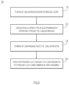
- a method of cooling an electromagnetic component assembly disposed in a power source for a welding or cutting system including the steps of: placing a tubular winding near or around a core and conducting a current for an electromagnetic operation through the tubular winding.
- the method further includes forming a flow passage inside the tubular winding and directing process fluid through the flow passage as the process fluid flows towards a torch assembly.
- the process fluid is plasma gas
- the torch assembly is a plasma arc torch assembly
- the plasma gas is ionized to create a plasma stream.
- the directing occurs during welding or cutting operations of the welding or cutting system. This eliminates risks associated with detecting a rise in temperature and also conserves energy because electrical components do not experience a relatively extreme rise in temperature between cooling cycles. Instead, when the electrical components are generating heat (e.g., during operation of the power source), cooling is provided. Further, cooling is provided with the process fluid that is used for the welding or cutting operation. No separate cooling fluid is required.
- the apparatus, configuration, and method direct process fluid (i.e., operational gas or liquid), such as plasma gas or water mist, through a passageway formed in a tubular winding and/or through a passageway formed in a core of an electromagnetic component assembly, disposed in a power source, to cool the electromagnetic component assembly.
- process fluid i.e., operational gas or liquid
- the passageway may be formed in other electrical components (e.g., resistors, capacitors, integrated circuits, computing components (e.g., microprocessors), etc.) included in the power source.
- coils in one or more of these other electrical components may be replaced with tubular windings that conduct current and provide a passageway for the process fluid to cool the respective electrical component.
- a holding component and/or a housing component of electrical components such as a core may be modified to form a passageway for the process fluid to cool the respective electrical component.
- the electromagnetic component assembly of the power source is typically used to deliver power for various operations and is modified to also pass the process fluid to a torch assembly, thereby using the process fluid to cool one or more of the electrical components therein. Consequently, the apparatus and configuration provide cooling without adding cooling-specific components to a power source. Moreover, the cooling provided by the process fluid provides efficient cooling and, thus, can replace or enhance cooling provided by other means. In fact, cooling-specific components, such as fans, can be removed from a power source and/or replaced with smaller and/or cheaper components. For example, a power source incorporating the passageway for the process fluid/configuration presented herein may not need a fan to force a flow of ambient air through the power source. Consequently, the cooling apparatus/configuration presented herein may reduce the cost, weight, and/or electrical consumption of a power source while still providing any electrical components included in the power source with sufficient cooling.
- liquid cooling and/or phase change cooling can only be implemented by adding (e.g., installing/including) cooling-specific components to a power source, insofar as cooling-specific components are dedicated to cooling and not directly involved in operational undertakings of the power source (e.g., transferring process fluid and electricity to a torch assembly).
- cooling-specific components are dedicated to cooling and not directly involved in operational undertakings of the power source (e.g., transferring process fluid and electricity to a torch assembly).
- liquid cooling requires a power source to include or define closed flow paths dedicated to passing a flow of liquid (e.g., water) through the power source exclusively for cooling.
- a power source utilizing phase change cooling may require one or more heat pipes with an internal fluid that evaporates at a low temperature (to pull energy away from an electrical component) to be bonded to a heat sink or heat transfer surface with a specific gap filler or bonding agent (e.g., a bonding agent that increases the resistance of the thermal bonded joint and slows the conduction of heat from the heat sink/heat transfer surface to the heat pipe).
- a specific gap filler or bonding agent e.g., a bonding agent that increases the resistance of the thermal bonded joint and slows the conduction of heat from the heat sink/heat transfer surface to the heat pipe.
- the power source need not include components dedicated solely to cooling the power source (e.g., liquid flow paths, heat pipes, bonding agents, fans, radiators, pumps, reservoirs, hoses, etc.). That is, the power source utilizes components that already exist in nearly all power sources (e.g., electrical windings and/or magnetic cores) to generate effective cooling. Moreover, a power source including the electromagnetic component assembly/configuration presented herein need not pass a second media (e.g., gas, liquid, etc.) through the power source to provide cooling. Instead, a processing fluid used to perform the cutting and/or welding operations is also used to cool the respective electrical components.
- a second media e.g., gas, liquid, etc.
- FIG. 1 is a perspective view illustrating a welding and/or cutting system (hereinafter a cutting system 100) that includes a process fluid supply 110 and a torch assembly 120, which are connected to a power source 200 having an electromagnetic component assembly 201 ( FIGs. 2 and 3 ) formed therein in accordance with an embodiment of the present disclosure.
- a welding and/or cutting system hereinafter a cutting system 100
- a process fluid supply 110 and a torch assembly 120
- a power source 200 having an electromagnetic component assembly 201 ( FIGs. 2 and 3 ) formed therein in accordance with an embodiment of the present disclosure.
- the cutting system 100 includes the power source 200 that supplies power to the torch assembly 120 while also controlling the flow of process fluid from a process fluid supply 110 to the torch assembly 120 (however, in other embodiments, the power source 200 might supply the process fluid itself).
- the process fluid supply 110 is connected to the power source 200 via a cable hose 112 and the power source 200 is connected to the torch assembly 120 via a cable hose 122.
- the cutting system 100 also includes a working lead formed of a cable hose 132 and a grounding clamp 130.
- the cable hose 112, the cable hose 122, and/or the cable hose 132 may each be any length.
- the opposing ends of cable hose 112, cable hose 122, and/or cable hose 132 may each be coupled to the power source 200, the torch assembly 120, the process fluid supply 110, or the grounding clamp 130 in any manner now known or developed hereafter (e.g., a releasable connection).
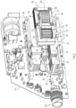
- the power source 200 includes an exterior housing 202. That is, a top cover 204, a bottom 206, a first side 208, a back 210 ( FIG. 2 ), a second side 212 ( FIG. 3 ), and a front 220 cooperate with each other to form the exterior housing 202 that defines an interior cavity 230 ( FIG. 2 ).
- the front 220 may include a control panel 222 with one or more knobs and/or a display but is not limited thereto.
- the front 220, the first side 208, and/or the second side 212 may include ventilation vents 224 to provide for circulation of ambient air but is not limited thereto. In alternative embodiments, the ventilation vents 224 are provided on the back 210 and/or the top cover 204 or are omitted altogether.
- the electromagnetic component assembly 201 utilizes compressed process fluid from the process fluid supply 110 to cool various electrical components in the power source 200 as the compressed process fluid flows through the electromagnetic component assembly 201, from the process fluid supply 110 to the torch assembly 120.
- the compressed process fluid flows from the process fluid supply 110 to the power source 200 via the cable hose 112.
- the compressed process fluid enters the power source 200 via a process fluid inlet port 211 ( FIG. 2 ).
- the process fluid inlet port 211 is located on the back 210 of the power source 200.
- the flow rate of the compressed process fluid may be controlled and/or regulated at the process fluid inlet port 211 by a flow controller 214 (e.g., a solenoid valve assembly).
- the compressed process fluid flows through the power source 200, as detailed below with reference to FIG. 3
- fourth, the compressed process fluid is supplied to the torch assembly 120 via a process fluid outlet port 226.
- the interior cavity 230 houses various components of the power source 200 and includes electrical components that in a given example are depicted as the electromagnetic component assembly 201.
- the power source 200 utilizes power from a power supply (not shown) to power various electrical components such as the electromagnetic component assembly 201 in the power source 200.
- a power plug 241 extends outside the power source 200 from the back 210 and mates with a power socket (not shown) to obtain current and/or voltage from a power supply and supply current and/or voltage (power) to the power source 200 via an external cord 242.
- the external cord 242 is then electrically connected to one or more internal cords or wires 244 that supply power to the electromagnetic component assembly 201 for various operations and/or supply power to the torch assembly 120 for welding and/or cutting operations. This is just an example and various ways now known or later developed to supply power to the power source 200 are within the scope of the present disclosure.
- the electromagnetic component assembly 201 may include a printer circuit board (PCB) 240 that extends perpendicularly upwards from the bottom 206 (e.g., parallel to the first side 208 and the second side 212 of the power source 200).
- PCB printer circuit board
- Various electrical components 260 are mounted directly or indirectly to the PCB 240 and are electrically connected directly or indirectly to the PCB 240.
- the electrical components 260 are operative to control supply of electricity and/or process fluid to the torch assembly 120 based on commands/signals received by the power source 200 (e.g., commands received at the control panel 222).
- the electrical components 260 include, but are not limited to, a first winding 262 wound around a first bobbin 264 and a second winding 266 wound around a second bobbin 268.
- the first winding 262 and the second winding 266 are connected via a center tap 270.
- the first winding 262 is housed inside a first core 272 and the second winding 266 is housed inside a second core 274. Further, the first winding 262 and the second winding 266 are around the first core 272 and the second core 274. Sizes and/or shapes and/or other attributes (e.g., lengths, thickness, etc.) of various windings and cores depend on a particular use case of the electrical components 260.
- the first winding 262, the center tap 270, and the second winding 266 are electrically hot because of a current flowing therein.
- the windings should be at a temperature below 225°C and preferably below 180°C.
- one or more sensors may be provided outside and/or inside the first core 272 and the second core 274 to monitor current and/or voltage flowing through the windings but the present disclosure is not limited thereto.
- the windings should be covered in one or more insulating materials to avoid the transfer of heat to other components in the power source 200, but is not limited thereto. That is, the windings include an outside dielectric layer to prevent short circuit from turn to turn. This layer can be a sleeve of insulation or a coating.
- heat sinks 250 are usually provided near the electromagnetic component assembly 201.
- the compressed process fluid dedicated to welding and/or cutting operations are now also used to cool the electromagnetic component assembly 201 during operations of the cutting system 100.
- the compressed process fluid enters the power source 200 via the process fluid inlet port 211 provided on the back 210 ( FIG. 2 ) into an internal closed flow path 280.
- the process fluid then flows through a first internal pipe 282 and into a first heat sink 252 from among the heat sinks 250.
- the process fluid flows through one or more of the heats sinks 250 and exits at the same first heat sink 252 to flow into the electromagnetic component assembly 201, as detailed below.
- At least a portion of the first winding 262 and/or at least a portion of the second winding 266, and/or the center tap 270 may be a copper tube or a conductive conduit that forms a passageway for the process fluid.
- the process fluid enters the first winding 262 via an inlet port 284, flows through the first winding 262 thereby cooling it, and into the second winding 266 via the center tap 270. Then, the process fluid exits the electromagnetic component assembly 201 via an outlet port 286 and is supplied to the process fluid outlet port 226 on the front 220 of the power source 200 via a second internal pipe 288.
- the compressed process fluid reaches the process fluid outlet port 226, the compressed process fluid is directed to the torch assembly 120.
- the process fluid outlet port 226 is largely described with respect to fluid transfer of a single fluid or the processing fluid; however, it is to be understood that the process fluid outlet port 226 may also allow the power source 200 to transfer additional process gasses and/or process fluids and/or electricity to the torch assembly 120.
- the front 220 also includes an additional port 134 ( FIG. 1 ) for the cable hose 132 that connects the working clamp 130 to the power source 200 and, typically, the port only provides an electrical connection and is unrelated to process fluid flow.
- the coil conducting wires of one or more windings are replaced with a conductive tube or conduit that still conducts the power required for the electric operations but also forms a passageway for the process fluid to cool the electromagnetic component assembly 201.
- the electrical components 260 may include a transformer that transforms high voltage-low amperage current received on a primary side (the first winding 262) to a low voltagehigh amperage current on a secondary side (the second winding 266), which is more desirable for cutting and/or welding operations.
- the electrical components 260 may also include an inductor to control the supply of electricity (avoid short-circuiting, etc.). The inductor helps control the current so that a steady and/or stable supply of electricity is provided within the power source 200 and/or to the torch assembly 120.
- FIG. 4 is an exploded simplified diagram of the electrical components 260 shown in FIG. 3 .
- the first winding 262 may be formed of coil or wire and is wound around the first bobbin 264 and/or a first core (when the winding are wound around the core).
- the first winding 262 forms a primary winding of the transformer.
- the center tap 270 connects the first winding 262 to the second winding 266 wound on the second bobbin 268.
- the second winding 266 is formed of a conductive tube or conduit and is a secondary winding of the transformer.
- a third winding 276 may also be wound around the second bobbin 268 and/or a second core (when the windings are wound around the core).
- the third winding 276 forms an inductor that controls and/or regulates the supply of electricity to the plasma torch (torch assembly 120).
- the third winding 276 is also formed of a conductive tube or conduit.
- the process fluid may flow into the center tap 270 and through the conductive tube formed by the second winding 266 and the third winding 276. That is, the center tap 270, the second winding 266, and the third winding 276, together, form a passageway for the process fluid.
- the process fluid exits the passageway at the passageway outlet 292 and is then supplied to the torch assembly 120.
- the first winding 262 may also be formed of a conductive tube or conduit and in this configuration, the process fluid enters the passageway inlet 290 and respectively flows through the first winding 262, the center tap 270, the second winding 266, and the third winding 276.
- the first winding 262, the center tap 270, the second winding 266, and the third winding 276, together form the passageway.
- the passageway may be formed by the first winding 262 and/or the center tap 270, the second winding 266, and/or the third winding 276.
- the electrical components 260 include a transformer 310 and an inductor 320.
- the transformer 310 has the first winding 262 (primary coil winding) and the second winding 266 (secondary conductive conduit or tubular winding).
- the second winding 266 is connected to the third winding 276 (conductive conduit or tubular winding) of the inductor 320 via the center tap 270 (a common tube).
- a copper tube is used (in place of a copper wire) to form the secondary coil of the transformer 310 and/or the coil of the inductor 320.
- a passageway may be formed by a single conductive tube that spans the secondary winding of the transformer 310 (the second winding 266) and the winding of the inductor 320 (the third winding 276).
- the primary coil (the first winding 262) of the transformer 310 may remain unchanged (a wire or coil).
- the process fluid e.g., plasma gas that will eventually be used to create plasma
- tubular winding(s) reduce the number of electrical connections needed in the power supply, decrease the number of parts included in the power supply, and improve cooling for the electromagnetic component assembly 201.
- This is but an example configuration of the electrical components 260 and the present disclosure is not limited thereto.
- the compressed process fluid may be plasma gas and, thus, once the compressed plasma gas reaches the torch assembly 120, the compressed plasma gas is directed through an arc in the torch assembly 120 to generate a stream of plasma.
- the electromagnetic component assembly 201 presented herein might also be used in welding systems, automated cutting systems, and/or any other system in which electrical components 260 require cooling and operational or process fluid is flowing from the power source 200 to the torch assembly 120. That is, the apparatus and configuration presented herein may be useful in power sources suitable for various types of welding or cutting.
- the process fluid might be any gas utilized during welding or cutting operations and need not necessarily be compressed gas.
- the process fluid might be shielding gas or water mist.
- a compressed process gas also takes advantage of the throttling effect of compressed gasses expanding and cooling. This creates a larger temperature differential between the cooler compressed gas and the higher temperature of heated surfaces which will drive higher convection cooling.
- the process fluid is the only media that travels through the formed passageway; no water, other liquids, or other gasses pass there through and no dedicated coolants are needed.
- the power source 200 does not include a fan and the process fluid cooling explained above replaces cooling provided by forced subsonic airflow created by the fan.
- the process fluid cooling may be in addition to a forced subsonic airflow system and, in these embodiments, the power source 200 might include one or more fans in the interior cavity 230 ( FIG. 2 ).
- the transformer 400 has two E-shaped cores 402 that face each other with the windings wound in spaces between the legs of the E-shaped cores 402.
- the primary winding 404 is a coil wire (depicted by dots)
- the secondary winding 406 is a conductive conduit (depicted by circles).
- the process fluid enters the transformer 400 via a transformer inlet port 408, flows through a passageway formed by the secondary winding 406, and exits the transformer 400 via a transformer outlet port 410.
- the passageway defined by the secondary winding 406 transfers heat away (e.g., from the electrical component) or cools the primary winding 404 and/or the secondary winding 406 (e.g., the electrical components) by having the process fluid flow therein.
- the transformer inlet port 408 and the transformer outlet port 410 may both be disposed in a vicinity or proximate to the bottom 206 but are not limited thereto; other configurations are within the scope of the present disclosure.
- the electromagnetic component assembly 500 includes the transformer 400 with two E-shaped cores 402 and an inductor 510 having an E-shaped core 512 and an I-shaped core 514.
- the two E-shaped cores 402 of the transformer 400 face each other and form a housing for both the primary winding 404 and the secondary winding 406.
- the two E-shaped cores 402 completely cover and/or surround the primary winding 404 and the secondary winding 406, thus providing protection from external elements (e.g., dust) and thus providing a sturdier and more reliable configuration (e.g. prevent leaks, fewer joints, etc.).
- An E-shaped core 512 and an I-shaped core 514 of the inductor 510 form a housing for an inductor winding 516.
- the E-shaped core 512 and the I-shaped core 514 when placed together ( FIG. 7B ), completely cover and/or surround the inductor winding 516. Accordingly, the inductor winding 516 is protected from external elements (e.g., dust) and has a sturdier and more reliable construction. Additionally, the manufacturing of the core is easier because it provides a simpler structure than an E-shaped core and is less costly as it requires less materials than an E-shaped core, for example. In FIG.
- the primary winding 404 is a coil wire(s) and the secondary winding 406 is a copper tube that conducts electricity and form a passageway for the process fluid.
- a shared tube 520 e.g. copper conduit connects the secondary winding 406 with the inductor winding 516. The shared tube 520 may form a part of the passageway for the process fluid.
- the process fluid is directed into the electromagnetic component assembly 500 at an input inlet 530, flows through the secondary winding 406 of the transformer 400 and into the inductor 510 via the shared tube 520.
- the process fluid then flows through the inductor 510 (the inductor winding 516) and is directed out of the electromagnetic component assembly 500 at an output outlet 532.
- one of the windings, multiple windings, and/or parts thereof may be replaced with a conductive tube and form a passageway for the process fluid.
- the passageway may be formed by a number of sub-passageways (e.g., have forks or split into parallel sub-passageways).
- FIG. 8 is a perspective view illustrating an electromagnetic component assembly 600 in which the windings 602 are coil windings and a non-conductive tubular conduit 604 for the process fluid is provided through the core 606.
- the process fluid is directed into the electromagnetic component assembly 600 at a core inlet port 608 disposed at a bottom of one side of the core 606 and is directed out of the electromagnetic component assembly 600 at a core outlet port 610 disposed at the bottom of the other side of the core 606.
- the tubular conduit 604 does not conduct electricity and is dedicated to directing the process fluid through the core 606 for the cooling.
- the tubular conduit 604 forms an upside down U-shape, as shown in FIG. 8 , to enhance the cooling of the windings 602.
- Other shapes and configurations of the tubular conduit 604 being provided through the core 606 are within the scope of the present disclosure.
- the tubular conduit 604 may form an I shape, a C shape, or V shape, or etc.
- the tubular conduit 604 might be split into a number of sub-conduits.
- the process fluid may also flow through one or more of the windings 602.
- the tubular conduit 604 may connect to the windings 602 (tubular conduit) to form one passageway for enhanced cooling using the process fluid.
- the tubular conduit 604 may provide a first passageway for a coolant fluid and the windings 602 may be formed of a tubular conduit to provide a second passageway for the process fluid.
- the cooling is then enhanced by having the coolant fluid flow through the first passageway and having the process fluid flow through the second passageway, thereby enhancing cooling of the electromagnetic component assembly 600.
- the electromagnetic component assembly may include a flow controller (not shown) dedicated to the assembly to control the amount of process fluid flowing into the inlet port 284.
- the flow controller may control the flow of process fluid into the passageway (from the first internal pipe 282) and may determine what portion or percentage of that flow of process fluid to divert to another passageway. That is, the passageway in the electromagnetic component assembly may have a split or fork (as explained above) and the flow controller may control an amount of process fluid that flows down a first pathway of the split (and into/onto a tubular conduit of a winding and/or core) and the process fluid not flowing down the first pathway may flow down a second pathway.
- the process fluid flowing along the second pathway may flow through another tubular conduit of another winding and/or core or may be diverted to another electromagnetic component assembly or another electrical component of the power source 200.
- one portion of the process fluid may be directed into the heat sinks 250 and another portion of the process fluid may be directed into the windings and/or core.
- one portion of the process fluid may be directed to a first electromagnetic component and another portion of the process fluid may be directed to a second electromagnetic component, thereby cooling both of the electromagnetic components at substantially same time.
- any electrical component with a passageway may include a dedicated flow controller so that the flow of process fluid through that component can be controlled, for example, to provide additional or decreased cooling to one particular electrical component as compared to other electrical components.
- the flow of process fluid may be controlled based on detected temperature received from a temperature sensor dedicated to that component. That is, when the detected temperature of that component exceeds a first threshold, the controller may direct 30% of the process fluid through the component. On the other hand, when the detected temperature rises to a second threshold (greater than the first threshold), the controller may direct 60% of the process fluid through the component.
- the controller may be pre-configured to change amount or portion of the process fluid to direct through the component based on the sensed temperature and a pre-configuration table that correlates temperature to an amount/portion of the process fluid (e.g. when sensed temperature exceeds 125°C, open valve 50% so that 1 ⁇ 2 of the process fluid flows through the component and when the sensed temperature exceeds 150°C, open valve 100% so that all of the process fluid flows through the component because it is overheating).
- a pre-configuration table that correlates temperature to an amount/portion of the process fluid (e.g. when sensed temperature exceeds 125°C, open valve 50% so that 1 ⁇ 2 of the process fluid flows through the component and when the sensed temperature exceeds 150°C, open valve 100% so that all of the process fluid flows through the component because it is overheating).
- a tubular winding is placed near or around a core.
- the tubular winding may be wound around the core.
- the tubular winding may be placed in at least one space formed by the core such that the core forms a housing for the tubular winding.
- the tubular winding may be a primary winding of one or more electrical components and/or a secondary winding of these electrical components, as shown in FIGs. 3-7B .
- a current and/or voltage is conducted for an electromagnetic operation through the tubular winding.
- the tubular winding may be a copper tube or another conductive conduit that conducts electricity there through for an electromagnetic operation and/or to provide power to the torch assembly 120, as shown in FIG. 2 .
- a flow passage is formed inside the tubular winding, as shown in FIGs. 3-7B and at 740, the process fluid is directed through the flow passage as the process fluid flows towards a torch assembly, thereby cooling the electromagnetic component assembly.
- a power source including an electromagnetic component assembly formed in accordance with the techniques presented herein may include any number of closed flow paths extending from an inlet to an outlet of an electromagnetic component assembly and/or of a power source.
- a flow path may include any number of branches so that any number of components incorporated into the flow path in series or in parallel.
Landscapes
- Engineering & Computer Science (AREA)
- Physics & Mathematics (AREA)
- Mechanical Engineering (AREA)
- Plasma & Fusion (AREA)
- Power Engineering (AREA)
- Optics & Photonics (AREA)
- Spectroscopy & Molecular Physics (AREA)
- Arc Welding Control (AREA)
- Arc Welding In General (AREA)
Claims (15)
- Un ensemble composant électromagnétique convenant à une source d'alimentation électrique pour un système de soudage ou de coupe, l'ensemble composant électromagnétique comprenant :un premier noyau (272) et un deuxième noyau (274) ; etétant caractérisé par :
un enroulement tubulaire placé près ou autour du premier noyau (272) et du deuxième noyau (274), où l'enroulement tubulaire conduit un courant pour une opération électromagnétique, l'enroulement tubulaire comprenant :une voie de passage pour un fluide de processus,une entrée (290), au niveau d'une extrémité de la voie de passage, recevant le fluide de processus, etune sortie (292), au niveau d'une autre extrémité de la voie de passage, dirigeant le fluide de processus en aval vers un ensemble chalumeau, où la voie de passage améliore le refroidissement de l'ensemble composant électromagnétique au fur et à mesure que le fluide de processus circule dans la voie de passage à partir de l'entrée jusqu'à la sortie. - L'ensemble composant électromagnétique de la revendication 1, où le fluide de processus est un gaz plasma et l'ensemble chalumeau est un ensemble chalumeau à arc de plasma, et où, lorsque le gaz plasma atteint l'ensemble chalumeau à arc de plasma, le gaz plasma est ionisé pour créer un flux de plasma.
- L'ensemble composant électromagnétique de la revendication 1, où le fluide de processus est un gaz de traitement ou un brouillard d'eau de traitement et est le seul milieu s'écoulant à travers la voie de passage et où le fluide de processus est fourni d'un dissipateur thermique (250) de la source d'alimentation électrique à l'entrée (290), ouoù l'enroulement tubulaire est un enroulement tubulaire en cuivre, ouoù le premier noyau (272), le deuxième noyau (274) et l'enroulement tubulaire forment un inducteur.
- L'ensemble composant électromagnétique de la revendication 3, où lorsque le premier noyau (272), le deuxième noyau (274) et l'enroulement tubulaire forment un inducteur, le premier noyau comprend un noyau en E et le deuxième noyau comprend un noyau en I qui fait face à une pluralité de branches du noyau en E et où l'enroulement tubulaire est enroulé dans des espaces formés entre la pluralité de branches du noyau en E.
- L'ensemble composant électromagnétique de la revendication 1, comprenant en outre : un enroulement en spirale (262) placé près d'au moins un noyau parmi le premier noyau (272) et le deuxième noyau (274) et conduisant le courant pour l'opération électromagnétique, où l'enroulement en spirale est un enroulement primaire d'un transformateur (310).
- L'ensemble composant électromagnétique de la revendication 5, où la voie de passage comprend :un premier conduit comportant l'entrée (290) et formant un enroulement secondaire (266) pour le transformateur (310) ;un deuxième conduit comportant la sortie (292) et formant un autre enroulement (276) pour un inducteur (320) ; etun conduit commun (270) raccordant le premier conduit et le deuxième conduit.
- L'ensemble composant électromagnétique de la revendication 5, où l'enroulement tubulaire forme un enroulement secondaire (266) du transformateur (310) et l'ensemble composant électromagnétique comprend en outre :un autre enroulement tubulaire (276) placé près du deuxième noyau (274) et formant un inducteur (320) ; etun conduit partagé (270) raccordant l'enroulement tubulaire à l'autre enroulement tubulaire,où l'autre enroulement tubulaire comprend :une autre voie de passage pour le fluide de processus,une autre entrée, au niveau d'une première extrémité de l'autre voie de passage, qui reçoit le fluide de processus provenant du conduit partagé (270), etune autre sortie, au niveau d'une deuxième extrémité de l'autre voie de passage, qui dirige le fluide de processus davantage en aval vers l'ensemble chalumeau, etoù cette autre voie de passage améliore le refroidissement de l'inducteur au fur et à mesure que le fluide de processus circule à travers cette autre voie de passage à partir de cette autre entrée jusqu'à cette autre sortie.
- L'ensemble composant électromagnétique de la revendication 1, comprenant en outre :un conduit passant à travers le premier noyau et le deuxième noyau ;une entrée de conduit, au niveau d'une première extrémité du conduit, qui reçoit un fluide de refroidissement ; etune sortie de conduit, au niveau d'une deuxième extrémité du conduit, qui dirige le fluide de refroidissement hors du conduit, où le conduit améliore le refroidissement de l'ensemble composant électromagnétique au fur et à mesure que le fluide de refroidissement circule à travers le conduit à partir de l'entrée de conduit jusqu'à la sortie de conduit.
- Une source d'alimentation électrique pour un système de soudage ou de coupe, comprenant :un logement externe (202) ;étant caractérisée par :
l'ensemble composant électromagnétique de la revendication 1, qui est disposé dans une cavité interne (230) formée par le logement externe (202). - La source d'alimentation électrique de la revendication 9, comprenant en outre :un orifice d'entrée (211) placé sur une paroi du logement externe (202) et recevant le fluide de processus provenant d'une alimentation en fluide ; etau moins un dissipateur thermique (250) placé dans la cavité interne (230) près de l'ensemble composant électromagnétique, recevant le fluide de processus provenant de l'orifice d'entrée (211), et fournissant le fluide de processus à l'entrée (290) ; oucomprenant en outre :
un orifice de sortie (226) placé sur une paroi du logement externe (202), recevant le fluide de processus provenant de la sortie (292), et dirigeant le fluide de processus vers l'ensemble chalumeau. - Un ensemble composant électromagnétique convenant à une source d'alimentation électrique pour un système de soudage ou de coupe, l'ensemble composant électromagnétique comprenant :
étant caractérisé par :un premier noyau (272) et un deuxième noyau (274) ;un enroulement en spirale placé près ou autour du premier noyau (272) et du deuxième noyau (274), et l'enroulement en spirale conduisant un courant pour une opération électromagnétique ;une voie de passage tubulaire passant à travers le premier noyau (272) et le deuxième noyau (274) ;une entrée (290), au niveau d'une extrémité de la voie de passage tubulaire, recevant un fluide de processus ; etune sortie (292), au niveau d'une autre extrémité de la voie de passage tubulaire, dirigeant le fluide de processus en aval vers un ensemble chalumeau, où la voie de passage tubulaire améliore le refroidissement de l'ensemble composant électromagnétique au fur et à mesure que le fluide de processus circule à travers la voie de passage tubulaire à partir de l'entrée jusqu'à la sortie. - L'ensemble composant électromagnétique de la revendication 11, où la voie de passage tubulaire ne conduit pas le courant et est en U, ou
où le fluide de processus est un gaz de traitement ou un brouillard d'eau de traitement et est le seul milieu s'écoulant à travers la voie de passage tubulaire et où le fluide de processus est fourni d'un dissipateur thermique (250) de la source d'alimentation électrique à l'entrée (290). - L'ensemble composant électromagnétique de la revendication 12, où lorsque la voie de passage tubulaire ne conduit pas le courant et est en U, l'entrée (290) et la sortie (292) sont formées au niveau d'une base du noyau.
- Un procédé de refroidissement d'un ensemble composant électromagnétique disposé dans une source d'alimentation électrique pour un système de soudage ou de coupe, le procédé étant caractérisé par les étapes suivantes consistant à :mettre en place un enroulement tubulaire près de ou autour d'un premier noyau (272) et d'un deuxième noyau (274) ;conduire un courant pour une opération électromagnétique dans l'enroulement tubulaire ;former un passage d'écoulement à l'intérieur de l'enroulement tubulaire ; etdiriger un fluide de processus à travers le passage d'écoulement au fur et à mesure que le fluide de processus s'écoule vers un ensemble chalumeau.
- Le procédé de la revendication 14, où le fluide de processus est un gaz plasma et l'ensemble chalumeau est un ensemble chalumeau à arc de plasma et où, lorsque le gaz plasma atteint l'ensemble chalumeau à arc de plasma, le gaz plasma est ionisé pour créer un flux de plasma, ou où le fait de diriger le fluide de processus à travers le passage d'écoulement se produit durant des opérations de soudage ou de coupe du système de soudage ou de coupe.
Applications Claiming Priority (2)
| Application Number | Priority Date | Filing Date | Title |
|---|---|---|---|
| US16/805,224 US12017294B2 (en) | 2020-02-28 | 2020-02-28 | Electromagnetic components cooling apparatus, method, and configuration |
| PCT/US2021/018472 WO2021173409A1 (fr) | 2020-02-28 | 2021-02-18 | Ensemble composant électromagnétique, bloc d'alimentation destiné au système de soudage ou de coupe pourvu d'un tel ensemble, et procédé de refroidissement d'un ensemble composant électromagnétique disposé dans un bloc d'alimentation pour le système de soudage ou de coupe |
Publications (2)
| Publication Number | Publication Date |
|---|---|
| EP4110546A1 EP4110546A1 (fr) | 2023-01-04 |
| EP4110546B1 true EP4110546B1 (fr) | 2024-04-03 |
Family
ID=74858832
Family Applications (1)
| Application Number | Title | Priority Date | Filing Date |
|---|---|---|---|
| EP21710171.6A Active EP4110546B1 (fr) | 2020-02-28 | 2021-02-18 | Ensemble composant électromagnétique, bloc d'alimentation destiné au système de soudage ou de coupe pourvu d'un tel ensemble, et procédé de refroidissement d'un ensemble composant électromagnétique disposé dans un bloc d'alimentation pour le système de soudage ou de coupe |
Country Status (5)
| Country | Link |
|---|---|
| US (1) | US12017294B2 (fr) |
| EP (1) | EP4110546B1 (fr) |
| CN (1) | CN115210025A (fr) |
| MX (1) | MX2022010032A (fr) |
| WO (1) | WO2021173409A1 (fr) |
Family Cites Families (41)
| Publication number | Priority date | Publication date | Assignee | Title |
|---|---|---|---|---|
| US4602140A (en) * | 1984-11-01 | 1986-07-22 | Mangels Industrial S.A. | Induction fluid heater |
| CA1253556A (fr) * | 1986-10-01 | 1989-05-02 | Richard J. Marceau | Un chauffe-fluide comprenant un noyau magnetique non conducteur ayant un enroulement primaire de fils conducteurs d'electricite |
| DE4415389A1 (de) * | 1994-05-02 | 1995-11-09 | Manfred Dr Ing Rudolph | Vorrichtung zur induktiven Durchlauferwärmung eines elektrisch leitfähigen, pumpfähigen Mediums |
| US6130818A (en) | 1999-05-27 | 2000-10-10 | Hamilton Sundstrand Corporation | Electronic assembly with fault tolerant cooling |
| US6717118B2 (en) * | 2001-06-26 | 2004-04-06 | Husky Injection Molding Systems, Ltd | Apparatus for inductive and resistive heating of an object |
| US6781100B2 (en) * | 2001-06-26 | 2004-08-24 | Husky Injection Molding Systems, Ltd. | Method for inductive and resistive heating of an object |
| KR100464809B1 (ko) * | 2001-08-22 | 2005-01-05 | 삼성전자주식회사 | 원격 플라즈마 발생기 |
| KR100493954B1 (ko) | 2002-02-09 | 2005-06-08 | 최대규 | 원격 플라즈마 발생장치 |
| US20040084443A1 (en) * | 2002-11-01 | 2004-05-06 | Ulrich Mark A. | Method and apparatus for induction heating of a wound core |
| US20040178874A1 (en) | 2003-03-14 | 2004-09-16 | Kaifler Erich Maximilian | Planar channel inductance |
| US7573000B2 (en) | 2003-07-11 | 2009-08-11 | Lincoln Global, Inc. | Power source for plasma device |
| US20050133201A1 (en) | 2003-12-22 | 2005-06-23 | I-Ming Liu | Radiation fin structure |
| KR100742659B1 (ko) * | 2005-04-12 | 2007-07-25 | 한양대학교 산학협력단 | 자성코어를 이용한 유도결합 플라즈마 발생장치 |
| US7459053B2 (en) * | 2005-05-11 | 2008-12-02 | Bone Jr Marvin J | Flux guide induction heating device and method of inductively heating elongated and nonuniform workpieces |
| KR100805557B1 (ko) * | 2006-04-24 | 2008-02-20 | 최대규 | 다중 마그네틱 코어가 결합된 유도 결합 플라즈마 소스 |
| US7397664B2 (en) | 2006-05-22 | 2008-07-08 | Sun Microsystems, Inc. | Heatspreader for single-device and multi-device modules |
| US7800901B2 (en) | 2006-09-13 | 2010-09-21 | Hypertherm, Inc. | Power supply cooling apparatus and configuration |
| DE102007001233A1 (de) * | 2007-01-08 | 2008-07-10 | Robert Bosch Gmbh | Windungselement für eine Spulenwicklung und Transformatoranordnung |
| KR20120084323A (ko) * | 2009-11-17 | 2012-07-27 | 에이비비 리써치 리미티드 | 격막을 갖는 전기 변압기 및 전기 변압기를 냉각하는 방법 |
| US8742665B2 (en) * | 2009-11-18 | 2014-06-03 | Applied Materials, Inc. | Plasma source design |
| US8269592B1 (en) | 2010-05-05 | 2012-09-18 | Lockheed Martin Corporation | Pulse transformer |
| US11072035B2 (en) | 2010-05-21 | 2021-07-27 | Illinois Tool Works Inc. | Auxiliary welding heating system |
| US8338749B2 (en) | 2010-08-06 | 2012-12-25 | Cammann, Inc. | Power booster for metal disintegrator |
| AT512069B1 (de) * | 2011-10-31 | 2016-01-15 | Fronius Int Gmbh | Widerstandsschweissvorrichtung |
| US8928443B2 (en) * | 2012-05-17 | 2015-01-06 | Elwha Llc | Electrical device with emergency cooling system |
| EP2682957B1 (fr) * | 2012-07-04 | 2019-05-15 | ABB Schweiz AG | Dispositif électromagnétique comprenant un agencement de refroidissement comprenant un thermosiphon agencé spécifiquement |
| US20140008354A1 (en) | 2012-07-06 | 2014-01-09 | Lincoln Global, Inc. | Method and system of using induction heating to heat consumable during hot wire process |
| US10109413B2 (en) * | 2013-02-01 | 2018-10-23 | The Trustees Of Dartmouth College | Multilayer conductors with integrated capacitors and associated systems and methods |
| CN104135139B (zh) | 2013-05-03 | 2018-01-26 | 胜美达电机(香港)有限公司 | 一种电源供应模块 |
| CN105229757B (zh) | 2013-05-14 | 2018-03-23 | 色玛图尔公司 | 具有动态可变的线圈形状的感应线圈 |
| KR101595285B1 (ko) | 2013-06-17 | 2016-02-19 | 대우조선해양 주식회사 | 모듈형 용접기 |
| WO2015094482A1 (fr) * | 2013-12-20 | 2015-06-25 | Ajax Tocco Magnethermic Corporation | Saturation périphérique cc de bande chauffante à flux transversal |
| JP6315256B2 (ja) * | 2013-12-26 | 2018-04-25 | 住友電装株式会社 | リアクトル |
| US9908195B2 (en) * | 2014-05-30 | 2018-03-06 | Hypertherm, Inc. | Plasma cutting system with efficient components |
| JP5729514B1 (ja) | 2014-06-14 | 2015-06-03 | プラスウェア株式会社 | プラズマ発生装置、液上溶融方法及び給電装置 |
| CN106714999B (zh) | 2014-08-18 | 2019-07-16 | 维美德公司 | 用于将管状型材磁脉冲焊接到柱形内部构件上的焊接头 |
| US10638554B2 (en) | 2014-12-23 | 2020-04-28 | Illinois Tool Works Inc. | Systems and methods for interchangeable induction heating systems |
| CN109644548B (zh) | 2016-05-02 | 2021-04-30 | 海别得公司 | 冷却等离子切割系统及相关的系统和方法 |
| US10987765B2 (en) | 2016-08-17 | 2021-04-27 | Illinois Tool Works Inc. | Induction weld bead shaping |
| US10730130B2 (en) | 2016-09-20 | 2020-08-04 | Illinois Tool Works Inc. | Field former for use in welding applications |
| US11239026B2 (en) | 2017-09-29 | 2022-02-01 | Illinois Tool Works Inc. | High-frequency transformers using solid wire for welding-type power supplies |
-
2020
- 2020-02-28 US US16/805,224 patent/US12017294B2/en active Active
-
2021
- 2021-02-18 MX MX2022010032A patent/MX2022010032A/es unknown
- 2021-02-18 WO PCT/US2021/018472 patent/WO2021173409A1/fr not_active Ceased
- 2021-02-18 EP EP21710171.6A patent/EP4110546B1/fr active Active
- 2021-02-18 CN CN202180017605.XA patent/CN115210025A/zh active Pending
Also Published As
| Publication number | Publication date |
|---|---|
| WO2021173409A1 (fr) | 2021-09-02 |
| CN115210025A (zh) | 2022-10-18 |
| US12017294B2 (en) | 2024-06-25 |
| EP4110546A1 (fr) | 2023-01-04 |
| US20210268596A1 (en) | 2021-09-02 |
| MX2022010032A (es) | 2022-09-02 |
Similar Documents
| Publication | Publication Date | Title |
|---|---|---|
| EP2909893B1 (fr) | Connecteur d'alimentation refroidi avec soupape d'arrêt, système de chauffage par induction et câble d'utilisation avec connecteur | |
| ES2736498T3 (es) | Procedimiento y aparato para un reactor químico de flujo continuo calentado eléctricamente de forma directa | |
| US7800901B2 (en) | Power supply cooling apparatus and configuration | |
| KR101950027B1 (ko) | 원격 플라즈마 생성기 | |
| AU2019226118B2 (en) | Power source cooling apparatus, method and configuration | |
| US9526161B2 (en) | High-frequency power supply device | |
| CN102696082A (zh) | 具有隔板的变压器及其冷却方法 | |
| US20170312863A1 (en) | Cooling Plasma Cutting Systems and Related Systems and Methods | |
| EP3215304A1 (fr) | Alimentation du type soudage ayant soufflerie | |
| EP4110546B1 (fr) | Ensemble composant électromagnétique, bloc d'alimentation destiné au système de soudage ou de coupe pourvu d'un tel ensemble, et procédé de refroidissement d'un ensemble composant électromagnétique disposé dans un bloc d'alimentation pour le système de soudage ou de coupe | |
| CN102159905A (zh) | 电磁感应加热单元及空调装置 | |
| JP7215663B2 (ja) | 誘導加熱コイル | |
| KR101460208B1 (ko) | 유도가열히터 | |
| JP4094032B2 (ja) | 水冷式トランスの水冷コイルとその水冷式トランス | |
| JP2000208240A (ja) | 高周波電源装置及び高周波誘導加熱装置 | |
| CN118380249B (zh) | 射频变压器、电离组件及等离子体产生装置 | |
| JP2000012340A (ja) | 水冷トランスおよびこの水冷トランスを用いた高周波誘導加熱装置 | |
| EP3163612B1 (fr) | Élément de refroidissement pour composants électroniques et dispositif électronique | |
| JP2009289880A (ja) | パワー電子機器 | |
| JP2007027216A (ja) | 小型大電力カレントトランス | |
| CN119699676A (zh) | 一种气溶胶发生装置 | |
| TWI442421B (zh) | 變壓器結構 | |
| CN117099178A (zh) | 变压器装置 | |
| KR20200002080U (ko) | 유입식 변압기 |
Legal Events
| Date | Code | Title | Description |
|---|---|---|---|
| STAA | Information on the status of an ep patent application or granted ep patent |
Free format text: STATUS: UNKNOWN |
|
| STAA | Information on the status of an ep patent application or granted ep patent |
Free format text: STATUS: THE INTERNATIONAL PUBLICATION HAS BEEN MADE |
|
| PUAI | Public reference made under article 153(3) epc to a published international application that has entered the european phase |
Free format text: ORIGINAL CODE: 0009012 |
|
| STAA | Information on the status of an ep patent application or granted ep patent |
Free format text: STATUS: REQUEST FOR EXAMINATION WAS MADE |
|
| 17P | Request for examination filed |
Effective date: 20220803 |
|
| AK | Designated contracting states |
Kind code of ref document: A1 Designated state(s): AL AT BE BG CH CY CZ DE DK EE ES FI FR GB GR HR HU IE IS IT LI LT LU LV MC MK MT NL NO PL PT RO RS SE SI SK SM TR |
|
| DAV | Request for validation of the european patent (deleted) | ||
| DAX | Request for extension of the european patent (deleted) | ||
| GRAP | Despatch of communication of intention to grant a patent |
Free format text: ORIGINAL CODE: EPIDOSNIGR1 |
|
| STAA | Information on the status of an ep patent application or granted ep patent |
Free format text: STATUS: GRANT OF PATENT IS INTENDED |
|
| INTG | Intention to grant announced |
Effective date: 20230921 |
|
| GRAS | Grant fee paid |
Free format text: ORIGINAL CODE: EPIDOSNIGR3 |
|
| P01 | Opt-out of the competence of the unified patent court (upc) registered |
Effective date: 20231220 |
|
| GRAA | (expected) grant |
Free format text: ORIGINAL CODE: 0009210 |
|
| STAA | Information on the status of an ep patent application or granted ep patent |
Free format text: STATUS: THE PATENT HAS BEEN GRANTED |
|
| AK | Designated contracting states |
Kind code of ref document: B1 Designated state(s): AL AT BE BG CH CY CZ DE DK EE ES FI FR GB GR HR HU IE IS IT LI LT LU LV MC MK MT NL NO PL PT RO RS SE SI SK SM TR |
|
| REG | Reference to a national code |
Ref country code: CH Ref legal event code: EP |
|
| REG | Reference to a national code |
Ref country code: DE Ref legal event code: R096 Ref document number: 602021011308 Country of ref document: DE |
|
| REG | Reference to a national code |
Ref country code: IE Ref legal event code: FG4D |
|
| REG | Reference to a national code |
Ref country code: LT Ref legal event code: MG9D |
|
| REG | Reference to a national code |
Ref country code: NL Ref legal event code: MP Effective date: 20240403 |
|
| REG | Reference to a national code |
Ref country code: AT Ref legal event code: MK05 Ref document number: 1671729 Country of ref document: AT Kind code of ref document: T Effective date: 20240403 |
|
| PG25 | Lapsed in a contracting state [announced via postgrant information from national office to epo] |
Ref country code: NL Free format text: LAPSE BECAUSE OF FAILURE TO SUBMIT A TRANSLATION OF THE DESCRIPTION OR TO PAY THE FEE WITHIN THE PRESCRIBED TIME-LIMIT Effective date: 20240403 |
|
| PG25 | Lapsed in a contracting state [announced via postgrant information from national office to epo] |
Ref country code: NL Free format text: LAPSE BECAUSE OF FAILURE TO SUBMIT A TRANSLATION OF THE DESCRIPTION OR TO PAY THE FEE WITHIN THE PRESCRIBED TIME-LIMIT Effective date: 20240403 |
|
| PG25 | Lapsed in a contracting state [announced via postgrant information from national office to epo] |
Ref country code: IS Free format text: LAPSE BECAUSE OF FAILURE TO SUBMIT A TRANSLATION OF THE DESCRIPTION OR TO PAY THE FEE WITHIN THE PRESCRIBED TIME-LIMIT Effective date: 20240803 |
|
| PG25 | Lapsed in a contracting state [announced via postgrant information from national office to epo] |
Ref country code: BG Free format text: LAPSE BECAUSE OF FAILURE TO SUBMIT A TRANSLATION OF THE DESCRIPTION OR TO PAY THE FEE WITHIN THE PRESCRIBED TIME-LIMIT Effective date: 20240403 |
|
| PG25 | Lapsed in a contracting state [announced via postgrant information from national office to epo] |
Ref country code: HR Free format text: LAPSE BECAUSE OF FAILURE TO SUBMIT A TRANSLATION OF THE DESCRIPTION OR TO PAY THE FEE WITHIN THE PRESCRIBED TIME-LIMIT Effective date: 20240403 Ref country code: FI Free format text: LAPSE BECAUSE OF FAILURE TO SUBMIT A TRANSLATION OF THE DESCRIPTION OR TO PAY THE FEE WITHIN THE PRESCRIBED TIME-LIMIT Effective date: 20240403 |
|
| PG25 | Lapsed in a contracting state [announced via postgrant information from national office to epo] |
Ref country code: GR Free format text: LAPSE BECAUSE OF FAILURE TO SUBMIT A TRANSLATION OF THE DESCRIPTION OR TO PAY THE FEE WITHIN THE PRESCRIBED TIME-LIMIT Effective date: 20240704 |
|
| PG25 | Lapsed in a contracting state [announced via postgrant information from national office to epo] |
Ref country code: PT Free format text: LAPSE BECAUSE OF FAILURE TO SUBMIT A TRANSLATION OF THE DESCRIPTION OR TO PAY THE FEE WITHIN THE PRESCRIBED TIME-LIMIT Effective date: 20240805 |
|
| PG25 | Lapsed in a contracting state [announced via postgrant information from national office to epo] |
Ref country code: ES Free format text: LAPSE BECAUSE OF FAILURE TO SUBMIT A TRANSLATION OF THE DESCRIPTION OR TO PAY THE FEE WITHIN THE PRESCRIBED TIME-LIMIT Effective date: 20240403 |
|
| PG25 | Lapsed in a contracting state [announced via postgrant information from national office to epo] |
Ref country code: CZ Free format text: LAPSE BECAUSE OF FAILURE TO SUBMIT A TRANSLATION OF THE DESCRIPTION OR TO PAY THE FEE WITHIN THE PRESCRIBED TIME-LIMIT Effective date: 20240403 |
|
| PG25 | Lapsed in a contracting state [announced via postgrant information from national office to epo] |
Ref country code: AT Free format text: LAPSE BECAUSE OF FAILURE TO SUBMIT A TRANSLATION OF THE DESCRIPTION OR TO PAY THE FEE WITHIN THE PRESCRIBED TIME-LIMIT Effective date: 20240403 |
|
| PG25 | Lapsed in a contracting state [announced via postgrant information from national office to epo] |
Ref country code: PL Free format text: LAPSE BECAUSE OF FAILURE TO SUBMIT A TRANSLATION OF THE DESCRIPTION OR TO PAY THE FEE WITHIN THE PRESCRIBED TIME-LIMIT Effective date: 20240403 |
|
| PG25 | Lapsed in a contracting state [announced via postgrant information from national office to epo] |
Ref country code: LV Free format text: LAPSE BECAUSE OF FAILURE TO SUBMIT A TRANSLATION OF THE DESCRIPTION OR TO PAY THE FEE WITHIN THE PRESCRIBED TIME-LIMIT Effective date: 20240403 |
|
| PG25 | Lapsed in a contracting state [announced via postgrant information from national office to epo] |
Ref country code: PT Free format text: LAPSE BECAUSE OF FAILURE TO SUBMIT A TRANSLATION OF THE DESCRIPTION OR TO PAY THE FEE WITHIN THE PRESCRIBED TIME-LIMIT Effective date: 20240805 Ref country code: PL Free format text: LAPSE BECAUSE OF FAILURE TO SUBMIT A TRANSLATION OF THE DESCRIPTION OR TO PAY THE FEE WITHIN THE PRESCRIBED TIME-LIMIT Effective date: 20240403 Ref country code: NO Free format text: LAPSE BECAUSE OF FAILURE TO SUBMIT A TRANSLATION OF THE DESCRIPTION OR TO PAY THE FEE WITHIN THE PRESCRIBED TIME-LIMIT Effective date: 20240703 Ref country code: LV Free format text: LAPSE BECAUSE OF FAILURE TO SUBMIT A TRANSLATION OF THE DESCRIPTION OR TO PAY THE FEE WITHIN THE PRESCRIBED TIME-LIMIT Effective date: 20240403 Ref country code: IS Free format text: LAPSE BECAUSE OF FAILURE TO SUBMIT A TRANSLATION OF THE DESCRIPTION OR TO PAY THE FEE WITHIN THE PRESCRIBED TIME-LIMIT Effective date: 20240803 Ref country code: HR Free format text: LAPSE BECAUSE OF FAILURE TO SUBMIT A TRANSLATION OF THE DESCRIPTION OR TO PAY THE FEE WITHIN THE PRESCRIBED TIME-LIMIT Effective date: 20240403 Ref country code: GR Free format text: LAPSE BECAUSE OF FAILURE TO SUBMIT A TRANSLATION OF THE DESCRIPTION OR TO PAY THE FEE WITHIN THE PRESCRIBED TIME-LIMIT Effective date: 20240704 Ref country code: FI Free format text: LAPSE BECAUSE OF FAILURE TO SUBMIT A TRANSLATION OF THE DESCRIPTION OR TO PAY THE FEE WITHIN THE PRESCRIBED TIME-LIMIT Effective date: 20240403 Ref country code: ES Free format text: LAPSE BECAUSE OF FAILURE TO SUBMIT A TRANSLATION OF THE DESCRIPTION OR TO PAY THE FEE WITHIN THE PRESCRIBED TIME-LIMIT Effective date: 20240403 Ref country code: CZ Free format text: LAPSE BECAUSE OF FAILURE TO SUBMIT A TRANSLATION OF THE DESCRIPTION OR TO PAY THE FEE WITHIN THE PRESCRIBED TIME-LIMIT Effective date: 20240403 Ref country code: BG Free format text: LAPSE BECAUSE OF FAILURE TO SUBMIT A TRANSLATION OF THE DESCRIPTION OR TO PAY THE FEE WITHIN THE PRESCRIBED TIME-LIMIT Effective date: 20240403 Ref country code: AT Free format text: LAPSE BECAUSE OF FAILURE TO SUBMIT A TRANSLATION OF THE DESCRIPTION OR TO PAY THE FEE WITHIN THE PRESCRIBED TIME-LIMIT Effective date: 20240403 Ref country code: RS Free format text: LAPSE BECAUSE OF FAILURE TO SUBMIT A TRANSLATION OF THE DESCRIPTION OR TO PAY THE FEE WITHIN THE PRESCRIBED TIME-LIMIT Effective date: 20240703 |
|
| REG | Reference to a national code |
Ref country code: DE Ref legal event code: R097 Ref document number: 602021011308 Country of ref document: DE |
|
| PG25 | Lapsed in a contracting state [announced via postgrant information from national office to epo] |
Ref country code: DK Free format text: LAPSE BECAUSE OF FAILURE TO SUBMIT A TRANSLATION OF THE DESCRIPTION OR TO PAY THE FEE WITHIN THE PRESCRIBED TIME-LIMIT Effective date: 20240403 |
|
| PG25 | Lapsed in a contracting state [announced via postgrant information from national office to epo] |
Ref country code: EE Free format text: LAPSE BECAUSE OF FAILURE TO SUBMIT A TRANSLATION OF THE DESCRIPTION OR TO PAY THE FEE WITHIN THE PRESCRIBED TIME-LIMIT Effective date: 20240403 |
|
| PG25 | Lapsed in a contracting state [announced via postgrant information from national office to epo] |
Ref country code: RO Free format text: LAPSE BECAUSE OF FAILURE TO SUBMIT A TRANSLATION OF THE DESCRIPTION OR TO PAY THE FEE WITHIN THE PRESCRIBED TIME-LIMIT Effective date: 20240403 Ref country code: SK Free format text: LAPSE BECAUSE OF FAILURE TO SUBMIT A TRANSLATION OF THE DESCRIPTION OR TO PAY THE FEE WITHIN THE PRESCRIBED TIME-LIMIT Effective date: 20240403 |
|
| PG25 | Lapsed in a contracting state [announced via postgrant information from national office to epo] |
Ref country code: SM Free format text: LAPSE BECAUSE OF FAILURE TO SUBMIT A TRANSLATION OF THE DESCRIPTION OR TO PAY THE FEE WITHIN THE PRESCRIBED TIME-LIMIT Effective date: 20240403 |
|
| PG25 | Lapsed in a contracting state [announced via postgrant information from national office to epo] |
Ref country code: SM Free format text: LAPSE BECAUSE OF FAILURE TO SUBMIT A TRANSLATION OF THE DESCRIPTION OR TO PAY THE FEE WITHIN THE PRESCRIBED TIME-LIMIT Effective date: 20240403 Ref country code: SK Free format text: LAPSE BECAUSE OF FAILURE TO SUBMIT A TRANSLATION OF THE DESCRIPTION OR TO PAY THE FEE WITHIN THE PRESCRIBED TIME-LIMIT Effective date: 20240403 Ref country code: RO Free format text: LAPSE BECAUSE OF FAILURE TO SUBMIT A TRANSLATION OF THE DESCRIPTION OR TO PAY THE FEE WITHIN THE PRESCRIBED TIME-LIMIT Effective date: 20240403 Ref country code: EE Free format text: LAPSE BECAUSE OF FAILURE TO SUBMIT A TRANSLATION OF THE DESCRIPTION OR TO PAY THE FEE WITHIN THE PRESCRIBED TIME-LIMIT Effective date: 20240403 Ref country code: DK Free format text: LAPSE BECAUSE OF FAILURE TO SUBMIT A TRANSLATION OF THE DESCRIPTION OR TO PAY THE FEE WITHIN THE PRESCRIBED TIME-LIMIT Effective date: 20240403 |
|
| PLBE | No opposition filed within time limit |
Free format text: ORIGINAL CODE: 0009261 |
|
| STAA | Information on the status of an ep patent application or granted ep patent |
Free format text: STATUS: NO OPPOSITION FILED WITHIN TIME LIMIT |
|
| 26N | No opposition filed |
Effective date: 20250106 |
|
| PG25 | Lapsed in a contracting state [announced via postgrant information from national office to epo] |
Ref country code: SI Free format text: LAPSE BECAUSE OF FAILURE TO SUBMIT A TRANSLATION OF THE DESCRIPTION OR TO PAY THE FEE WITHIN THE PRESCRIBED TIME-LIMIT Effective date: 20240403 |
|
| PG25 | Lapsed in a contracting state [announced via postgrant information from national office to epo] |
Ref country code: SE Free format text: LAPSE BECAUSE OF FAILURE TO SUBMIT A TRANSLATION OF THE DESCRIPTION OR TO PAY THE FEE WITHIN THE PRESCRIBED TIME-LIMIT Effective date: 20240403 |
|
| PG25 | Lapsed in a contracting state [announced via postgrant information from national office to epo] |
Ref country code: MC Free format text: LAPSE BECAUSE OF FAILURE TO SUBMIT A TRANSLATION OF THE DESCRIPTION OR TO PAY THE FEE WITHIN THE PRESCRIBED TIME-LIMIT Effective date: 20240403 |
|
| REG | Reference to a national code |
Ref country code: CH Ref legal event code: PL |
|
| PG25 | Lapsed in a contracting state [announced via postgrant information from national office to epo] |
Ref country code: LU Free format text: LAPSE BECAUSE OF NON-PAYMENT OF DUE FEES Effective date: 20250218 |
|
| PG25 | Lapsed in a contracting state [announced via postgrant information from national office to epo] |
Ref country code: CH Free format text: LAPSE BECAUSE OF NON-PAYMENT OF DUE FEES Effective date: 20250228 |
|
| GBPC | Gb: european patent ceased through non-payment of renewal fee |
Effective date: 20250218 |
|
| REG | Reference to a national code |
Ref country code: BE Ref legal event code: MM Effective date: 20250228 |
|
| PG25 | Lapsed in a contracting state [announced via postgrant information from national office to epo] |
Ref country code: GB Free format text: LAPSE BECAUSE OF NON-PAYMENT OF DUE FEES Effective date: 20250218 |
|
| PG25 | Lapsed in a contracting state [announced via postgrant information from national office to epo] |
Ref country code: FR Free format text: LAPSE BECAUSE OF NON-PAYMENT OF DUE FEES Effective date: 20250228 |
|
| PG25 | Lapsed in a contracting state [announced via postgrant information from national office to epo] |
Ref country code: BE Free format text: LAPSE BECAUSE OF NON-PAYMENT OF DUE FEES Effective date: 20250228 |
|
| PG25 | Lapsed in a contracting state [announced via postgrant information from national office to epo] |
Ref country code: IE Free format text: LAPSE BECAUSE OF NON-PAYMENT OF DUE FEES Effective date: 20250218 |
|
| PG25 | Lapsed in a contracting state [announced via postgrant information from national office to epo] |
Ref country code: IT Free format text: LAPSE BECAUSE OF FAILURE TO SUBMIT A TRANSLATION OF THE DESCRIPTION OR TO PAY THE FEE WITHIN THE PRESCRIBED TIME-LIMIT Effective date: 20240403 |
|
| PGFP | Annual fee paid to national office [announced via postgrant information from national office to epo] |
Ref country code: DE Payment date: 20260227 Year of fee payment: 6 |