EP4112221A1 - Système de traitement - Google Patents
Système de traitement Download PDFInfo
- Publication number
- EP4112221A1 EP4112221A1 EP20921895.7A EP20921895A EP4112221A1 EP 4112221 A1 EP4112221 A1 EP 4112221A1 EP 20921895 A EP20921895 A EP 20921895A EP 4112221 A1 EP4112221 A1 EP 4112221A1
- Authority
- EP
- European Patent Office
- Prior art keywords
- processing system
- processing
- stage
- holding part
- workpiece
- Prior art date
- Legal status (The legal status is an assumption and is not a legal conclusion. Google has not performed a legal analysis and makes no representation as to the accuracy of the status listed.)
- Pending
Links
Images


Classifications
-
- B—PERFORMING OPERATIONS; TRANSPORTING
- B23—MACHINE TOOLS; METAL-WORKING NOT OTHERWISE PROVIDED FOR
- B23K—SOLDERING OR UNSOLDERING; WELDING; CLADDING OR PLATING BY SOLDERING OR WELDING; CUTTING BY APPLYING HEAT LOCALLY, e.g. FLAME CUTTING; WORKING BY LASER BEAM
- B23K26/00—Working by laser beam, e.g. welding, cutting or boring
- B23K26/34—Laser welding for purposes other than joining
- B23K26/342—Build-up welding
-
- B—PERFORMING OPERATIONS; TRANSPORTING
- B23—MACHINE TOOLS; METAL-WORKING NOT OTHERWISE PROVIDED FOR
- B23K—SOLDERING OR UNSOLDERING; WELDING; CLADDING OR PLATING BY SOLDERING OR WELDING; CUTTING BY APPLYING HEAT LOCALLY, e.g. FLAME CUTTING; WORKING BY LASER BEAM
- B23K26/00—Working by laser beam, e.g. welding, cutting or boring
- B23K26/02—Positioning or observing the workpiece, e.g. with respect to the point of impact; Aligning, aiming or focusing the laser beam
- B23K26/03—Observing, e.g. monitoring, the workpiece
-
- B—PERFORMING OPERATIONS; TRANSPORTING
- B22—CASTING; POWDER METALLURGY
- B22F—WORKING METALLIC POWDER; MANUFACTURE OF ARTICLES FROM METALLIC POWDER; MAKING METALLIC POWDER; APPARATUS OR DEVICES SPECIALLY ADAPTED FOR METALLIC POWDER
- B22F10/00—Additive manufacturing of workpieces or articles from metallic powder
- B22F10/20—Direct sintering or melting
- B22F10/25—Direct deposition of metal particles, e.g. direct metal deposition [DMD] or laser engineered net shaping [LENS]
-
- B—PERFORMING OPERATIONS; TRANSPORTING
- B22—CASTING; POWDER METALLURGY
- B22F—WORKING METALLIC POWDER; MANUFACTURE OF ARTICLES FROM METALLIC POWDER; MAKING METALLIC POWDER; APPARATUS OR DEVICES SPECIALLY ADAPTED FOR METALLIC POWDER
- B22F10/00—Additive manufacturing of workpieces or articles from metallic powder
- B22F10/30—Process control
- B22F10/31—Calibration of process steps or apparatus settings, e.g. before or during manufacturing
-
- B—PERFORMING OPERATIONS; TRANSPORTING
- B22—CASTING; POWDER METALLURGY
- B22F—WORKING METALLIC POWDER; MANUFACTURE OF ARTICLES FROM METALLIC POWDER; MAKING METALLIC POWDER; APPARATUS OR DEVICES SPECIALLY ADAPTED FOR METALLIC POWDER
- B22F10/00—Additive manufacturing of workpieces or articles from metallic powder
- B22F10/50—Treatment of workpieces or articles during build-up, e.g. treatments applied to fused layers during build-up
-
- B—PERFORMING OPERATIONS; TRANSPORTING
- B22—CASTING; POWDER METALLURGY
- B22F—WORKING METALLIC POWDER; MANUFACTURE OF ARTICLES FROM METALLIC POWDER; MAKING METALLIC POWDER; APPARATUS OR DEVICES SPECIALLY ADAPTED FOR METALLIC POWDER
- B22F10/00—Additive manufacturing of workpieces or articles from metallic powder
- B22F10/60—Treatment of workpieces or articles after build-up
- B22F10/66—Treatment of workpieces or articles after build-up by mechanical means
-
- B—PERFORMING OPERATIONS; TRANSPORTING
- B22—CASTING; POWDER METALLURGY
- B22F—WORKING METALLIC POWDER; MANUFACTURE OF ARTICLES FROM METALLIC POWDER; MAKING METALLIC POWDER; APPARATUS OR DEVICES SPECIALLY ADAPTED FOR METALLIC POWDER
- B22F10/00—Additive manufacturing of workpieces or articles from metallic powder
- B22F10/80—Data acquisition or data processing
- B22F10/85—Data acquisition or data processing for controlling or regulating additive manufacturing processes
-
- B—PERFORMING OPERATIONS; TRANSPORTING
- B22—CASTING; POWDER METALLURGY
- B22F—WORKING METALLIC POWDER; MANUFACTURE OF ARTICLES FROM METALLIC POWDER; MAKING METALLIC POWDER; APPARATUS OR DEVICES SPECIALLY ADAPTED FOR METALLIC POWDER
- B22F12/00—Apparatus or devices specially adapted for additive manufacturing; Auxiliary means for additive manufacturing; Combinations of additive manufacturing apparatus or devices with other processing apparatus or devices
- B22F12/20—Cooling means
-
- B—PERFORMING OPERATIONS; TRANSPORTING
- B22—CASTING; POWDER METALLURGY
- B22F—WORKING METALLIC POWDER; MANUFACTURE OF ARTICLES FROM METALLIC POWDER; MAKING METALLIC POWDER; APPARATUS OR DEVICES SPECIALLY ADAPTED FOR METALLIC POWDER
- B22F12/00—Apparatus or devices specially adapted for additive manufacturing; Auxiliary means for additive manufacturing; Combinations of additive manufacturing apparatus or devices with other processing apparatus or devices
- B22F12/30—Platforms or substrates
- B22F12/37—Rotatable
-
- B—PERFORMING OPERATIONS; TRANSPORTING
- B22—CASTING; POWDER METALLURGY
- B22F—WORKING METALLIC POWDER; MANUFACTURE OF ARTICLES FROM METALLIC POWDER; MAKING METALLIC POWDER; APPARATUS OR DEVICES SPECIALLY ADAPTED FOR METALLIC POWDER
- B22F12/00—Apparatus or devices specially adapted for additive manufacturing; Auxiliary means for additive manufacturing; Combinations of additive manufacturing apparatus or devices with other processing apparatus or devices
- B22F12/90—Means for process control, e.g. cameras or sensors
-
- B—PERFORMING OPERATIONS; TRANSPORTING
- B23—MACHINE TOOLS; METAL-WORKING NOT OTHERWISE PROVIDED FOR
- B23K—SOLDERING OR UNSOLDERING; WELDING; CLADDING OR PLATING BY SOLDERING OR WELDING; CUTTING BY APPLYING HEAT LOCALLY, e.g. FLAME CUTTING; WORKING BY LASER BEAM
- B23K26/00—Working by laser beam, e.g. welding, cutting or boring
- B23K26/08—Devices involving relative movement between laser beam and workpiece
- B23K26/0823—Devices involving rotation of the workpiece
-
- B—PERFORMING OPERATIONS; TRANSPORTING
- B23—MACHINE TOOLS; METAL-WORKING NOT OTHERWISE PROVIDED FOR
- B23K—SOLDERING OR UNSOLDERING; WELDING; CLADDING OR PLATING BY SOLDERING OR WELDING; CUTTING BY APPLYING HEAT LOCALLY, e.g. FLAME CUTTING; WORKING BY LASER BEAM
- B23K26/00—Working by laser beam, e.g. welding, cutting or boring
- B23K26/08—Devices involving relative movement between laser beam and workpiece
- B23K26/0869—Devices involving movement of the laser head in at least one axial direction
- B23K26/0876—Devices involving movement of the laser head in at least one axial direction in at least two axial directions
-
- B—PERFORMING OPERATIONS; TRANSPORTING
- B23—MACHINE TOOLS; METAL-WORKING NOT OTHERWISE PROVIDED FOR
- B23K—SOLDERING OR UNSOLDERING; WELDING; CLADDING OR PLATING BY SOLDERING OR WELDING; CUTTING BY APPLYING HEAT LOCALLY, e.g. FLAME CUTTING; WORKING BY LASER BEAM
- B23K26/00—Working by laser beam, e.g. welding, cutting or boring
- B23K26/12—Working by laser beam, e.g. welding, cutting or boring in a special environment or atmosphere, e.g. in an enclosure
- B23K26/127—Working by laser beam, e.g. welding, cutting or boring in a special environment or atmosphere, e.g. in an enclosure in an enclosure
-
- B—PERFORMING OPERATIONS; TRANSPORTING
- B23—MACHINE TOOLS; METAL-WORKING NOT OTHERWISE PROVIDED FOR
- B23K—SOLDERING OR UNSOLDERING; WELDING; CLADDING OR PLATING BY SOLDERING OR WELDING; CUTTING BY APPLYING HEAT LOCALLY, e.g. FLAME CUTTING; WORKING BY LASER BEAM
- B23K26/00—Working by laser beam, e.g. welding, cutting or boring
- B23K26/14—Working by laser beam, e.g. welding, cutting or boring using a fluid stream, e.g. a jet of gas, in conjunction with the laser beam; Nozzles therefor
- B23K26/144—Working by laser beam, e.g. welding, cutting or boring using a fluid stream, e.g. a jet of gas, in conjunction with the laser beam; Nozzles therefor the fluid stream containing particles, e.g. powder
-
- B—PERFORMING OPERATIONS; TRANSPORTING
- B23—MACHINE TOOLS; METAL-WORKING NOT OTHERWISE PROVIDED FOR
- B23K—SOLDERING OR UNSOLDERING; WELDING; CLADDING OR PLATING BY SOLDERING OR WELDING; CUTTING BY APPLYING HEAT LOCALLY, e.g. FLAME CUTTING; WORKING BY LASER BEAM
- B23K26/00—Working by laser beam, e.g. welding, cutting or boring
- B23K26/14—Working by laser beam, e.g. welding, cutting or boring using a fluid stream, e.g. a jet of gas, in conjunction with the laser beam; Nozzles therefor
- B23K26/1462—Nozzles; Features related to nozzles
- B23K26/1464—Supply to, or discharge from, nozzles of media, e.g. gas, powder, wire
- B23K26/147—Features outside the nozzle for feeding the fluid stream towards the workpiece
-
- B—PERFORMING OPERATIONS; TRANSPORTING
- B23—MACHINE TOOLS; METAL-WORKING NOT OTHERWISE PROVIDED FOR
- B23K—SOLDERING OR UNSOLDERING; WELDING; CLADDING OR PLATING BY SOLDERING OR WELDING; CUTTING BY APPLYING HEAT LOCALLY, e.g. FLAME CUTTING; WORKING BY LASER BEAM
- B23K26/00—Working by laser beam, e.g. welding, cutting or boring
- B23K26/34—Laser welding for purposes other than joining
-
- B—PERFORMING OPERATIONS; TRANSPORTING
- B23—MACHINE TOOLS; METAL-WORKING NOT OTHERWISE PROVIDED FOR
- B23K—SOLDERING OR UNSOLDERING; WELDING; CLADDING OR PLATING BY SOLDERING OR WELDING; CUTTING BY APPLYING HEAT LOCALLY, e.g. FLAME CUTTING; WORKING BY LASER BEAM
- B23K37/00—Auxiliary devices or processes, not specially adapted for a procedure covered by only one of the other main groups of this subclass
- B23K37/02—Carriages for supporting the welding or cutting element
- B23K37/0211—Carriages for supporting the welding or cutting element travelling on a guide member, e.g. rail, track
- B23K37/0235—Carriages for supporting the welding or cutting element travelling on a guide member, e.g. rail, track the guide member forming part of a portal
-
- B—PERFORMING OPERATIONS; TRANSPORTING
- B29—WORKING OF PLASTICS; WORKING OF SUBSTANCES IN A PLASTIC STATE IN GENERAL
- B29C—SHAPING OR JOINING OF PLASTICS; SHAPING OF MATERIAL IN A PLASTIC STATE, NOT OTHERWISE PROVIDED FOR; AFTER-TREATMENT OF THE SHAPED PRODUCTS, e.g. REPAIRING
- B29C64/00—Additive manufacturing, i.e. manufacturing of three-dimensional [3D] objects by additive deposition, additive agglomeration or additive layering, e.g. by 3D printing, stereolithography or selective laser sintering
- B29C64/20—Apparatus for additive manufacturing; Details thereof or accessories therefor
- B29C64/227—Driving means
- B29C64/236—Driving means for motion in a direction within the plane of a layer
-
- B—PERFORMING OPERATIONS; TRANSPORTING
- B29—WORKING OF PLASTICS; WORKING OF SUBSTANCES IN A PLASTIC STATE IN GENERAL
- B29C—SHAPING OR JOINING OF PLASTICS; SHAPING OF MATERIAL IN A PLASTIC STATE, NOT OTHERWISE PROVIDED FOR; AFTER-TREATMENT OF THE SHAPED PRODUCTS, e.g. REPAIRING
- B29C64/00—Additive manufacturing, i.e. manufacturing of three-dimensional [3D] objects by additive deposition, additive agglomeration or additive layering, e.g. by 3D printing, stereolithography or selective laser sintering
- B29C64/20—Apparatus for additive manufacturing; Details thereof or accessories therefor
- B29C64/227—Driving means
- B29C64/241—Driving means for rotary motion
-
- B—PERFORMING OPERATIONS; TRANSPORTING
- B29—WORKING OF PLASTICS; WORKING OF SUBSTANCES IN A PLASTIC STATE IN GENERAL
- B29C—SHAPING OR JOINING OF PLASTICS; SHAPING OF MATERIAL IN A PLASTIC STATE, NOT OTHERWISE PROVIDED FOR; AFTER-TREATMENT OF THE SHAPED PRODUCTS, e.g. REPAIRING
- B29C64/00—Additive manufacturing, i.e. manufacturing of three-dimensional [3D] objects by additive deposition, additive agglomeration or additive layering, e.g. by 3D printing, stereolithography or selective laser sintering
- B29C64/20—Apparatus for additive manufacturing; Details thereof or accessories therefor
- B29C64/245—Platforms or substrates
-
- B—PERFORMING OPERATIONS; TRANSPORTING
- B29—WORKING OF PLASTICS; WORKING OF SUBSTANCES IN A PLASTIC STATE IN GENERAL
- B29C—SHAPING OR JOINING OF PLASTICS; SHAPING OF MATERIAL IN A PLASTIC STATE, NOT OTHERWISE PROVIDED FOR; AFTER-TREATMENT OF THE SHAPED PRODUCTS, e.g. REPAIRING
- B29C64/00—Additive manufacturing, i.e. manufacturing of three-dimensional [3D] objects by additive deposition, additive agglomeration or additive layering, e.g. by 3D printing, stereolithography or selective laser sintering
- B29C64/20—Apparatus for additive manufacturing; Details thereof or accessories therefor
- B29C64/264—Arrangements for irradiation
-
- B—PERFORMING OPERATIONS; TRANSPORTING
- B29—WORKING OF PLASTICS; WORKING OF SUBSTANCES IN A PLASTIC STATE IN GENERAL
- B29C—SHAPING OR JOINING OF PLASTICS; SHAPING OF MATERIAL IN A PLASTIC STATE, NOT OTHERWISE PROVIDED FOR; AFTER-TREATMENT OF THE SHAPED PRODUCTS, e.g. REPAIRING
- B29C64/00—Additive manufacturing, i.e. manufacturing of three-dimensional [3D] objects by additive deposition, additive agglomeration or additive layering, e.g. by 3D printing, stereolithography or selective laser sintering
- B29C64/30—Auxiliary operations or equipment
- B29C64/364—Conditioning of environment
- B29C64/371—Conditioning of environment using an environment other than air, e.g. inert gas
-
- B—PERFORMING OPERATIONS; TRANSPORTING
- B29—WORKING OF PLASTICS; WORKING OF SUBSTANCES IN A PLASTIC STATE IN GENERAL
- B29C—SHAPING OR JOINING OF PLASTICS; SHAPING OF MATERIAL IN A PLASTIC STATE, NOT OTHERWISE PROVIDED FOR; AFTER-TREATMENT OF THE SHAPED PRODUCTS, e.g. REPAIRING
- B29C64/00—Additive manufacturing, i.e. manufacturing of three-dimensional [3D] objects by additive deposition, additive agglomeration or additive layering, e.g. by 3D printing, stereolithography or selective laser sintering
- B29C64/30—Auxiliary operations or equipment
- B29C64/386—Data acquisition or data processing for additive manufacturing
- B29C64/393—Data acquisition or data processing for additive manufacturing for controlling or regulating additive manufacturing processes
-
- B—PERFORMING OPERATIONS; TRANSPORTING
- B33—ADDITIVE MANUFACTURING TECHNOLOGY
- B33Y—ADDITIVE MANUFACTURING, i.e. MANUFACTURING OF THREE-DIMENSIONAL [3D] OBJECTS BY ADDITIVE DEPOSITION, ADDITIVE AGGLOMERATION OR ADDITIVE LAYERING, e.g. BY 3D PRINTING, STEREOLITHOGRAPHY OR SELECTIVE LASER SINTERING
- B33Y30/00—Apparatus for additive manufacturing; Details thereof or accessories therefor
-
- B—PERFORMING OPERATIONS; TRANSPORTING
- B33—ADDITIVE MANUFACTURING TECHNOLOGY
- B33Y—ADDITIVE MANUFACTURING, i.e. MANUFACTURING OF THREE-DIMENSIONAL [3D] OBJECTS BY ADDITIVE DEPOSITION, ADDITIVE AGGLOMERATION OR ADDITIVE LAYERING, e.g. BY 3D PRINTING, STEREOLITHOGRAPHY OR SELECTIVE LASER SINTERING
- B33Y50/00—Data acquisition or data processing for additive manufacturing
- B33Y50/02—Data acquisition or data processing for additive manufacturing for controlling or regulating additive manufacturing processes
-
- G—PHYSICS
- G01—MEASURING; TESTING
- G01B—MEASURING LENGTH, THICKNESS OR SIMILAR LINEAR DIMENSIONS; MEASURING ANGLES; MEASURING AREAS; MEASURING IRREGULARITIES OF SURFACES OR CONTOURS
- G01B11/00—Measuring arrangements characterised by the use of optical techniques
- G01B11/14—Measuring arrangements characterised by the use of optical techniques for measuring distance or clearance between spaced objects or spaced apertures
-
- G—PHYSICS
- G05—CONTROLLING; REGULATING
- G05B—CONTROL OR REGULATING SYSTEMS IN GENERAL; FUNCTIONAL ELEMENTS OF SUCH SYSTEMS; MONITORING OR TESTING ARRANGEMENTS FOR SUCH SYSTEMS OR ELEMENTS
- G05B19/00—Program-control systems
- G05B19/02—Program-control systems electric
- G05B19/18—Numerical control [NC], i.e. automatically operating machines, in particular machine tools, e.g. in a manufacturing environment, so as to execute positioning, movement or co-ordinated operations by means of program data in numerical form
- G05B19/401—Numerical control [NC], i.e. automatically operating machines, in particular machine tools, e.g. in a manufacturing environment, so as to execute positioning, movement or co-ordinated operations by means of program data in numerical form characterised by control arrangements for measuring, e.g. calibration and initialisation, measuring workpiece for machining purposes
-
- B—PERFORMING OPERATIONS; TRANSPORTING
- B22—CASTING; POWDER METALLURGY
- B22F—WORKING METALLIC POWDER; MANUFACTURE OF ARTICLES FROM METALLIC POWDER; MAKING METALLIC POWDER; APPARATUS OR DEVICES SPECIALLY ADAPTED FOR METALLIC POWDER
- B22F12/00—Apparatus or devices specially adapted for additive manufacturing; Auxiliary means for additive manufacturing; Combinations of additive manufacturing apparatus or devices with other processing apparatus or devices
- B22F12/40—Radiation means
- B22F12/46—Radiation means with translatory movement
- B22F12/48—Radiation means with translatory movement in height, e.g. perpendicular to the deposition plane
-
- B—PERFORMING OPERATIONS; TRANSPORTING
- B22—CASTING; POWDER METALLURGY
- B22F—WORKING METALLIC POWDER; MANUFACTURE OF ARTICLES FROM METALLIC POWDER; MAKING METALLIC POWDER; APPARATUS OR DEVICES SPECIALLY ADAPTED FOR METALLIC POWDER
- B22F2999/00—Aspects linked to processes or compositions used in powder metallurgy
-
- B—PERFORMING OPERATIONS; TRANSPORTING
- B23—MACHINE TOOLS; METAL-WORKING NOT OTHERWISE PROVIDED FOR
- B23K—SOLDERING OR UNSOLDERING; WELDING; CLADDING OR PLATING BY SOLDERING OR WELDING; CUTTING BY APPLYING HEAT LOCALLY, e.g. FLAME CUTTING; WORKING BY LASER BEAM
- B23K2101/00—Articles made by soldering, welding or cutting
- B23K2101/04—Tubular or hollow articles
- B23K2101/06—Tubes
-
- B—PERFORMING OPERATIONS; TRANSPORTING
- B23—MACHINE TOOLS; METAL-WORKING NOT OTHERWISE PROVIDED FOR
- B23K—SOLDERING OR UNSOLDERING; WELDING; CLADDING OR PLATING BY SOLDERING OR WELDING; CUTTING BY APPLYING HEAT LOCALLY, e.g. FLAME CUTTING; WORKING BY LASER BEAM
- B23K26/00—Working by laser beam, e.g. welding, cutting or boring
- B23K26/70—Auxiliary operations or equipment
- B23K26/702—Auxiliary equipment
- B23K26/703—Cooling arrangements
-
- B—PERFORMING OPERATIONS; TRANSPORTING
- B33—ADDITIVE MANUFACTURING TECHNOLOGY
- B33Y—ADDITIVE MANUFACTURING, i.e. MANUFACTURING OF THREE-DIMENSIONAL [3D] OBJECTS BY ADDITIVE DEPOSITION, ADDITIVE AGGLOMERATION OR ADDITIVE LAYERING, e.g. BY 3D PRINTING, STEREOLITHOGRAPHY OR SELECTIVE LASER SINTERING
- B33Y10/00—Processes of additive manufacturing
Definitions
- the present invention relates to a processing system that is configured to process an object, for example.
- Patent Literature 1 discloses a processing system that is configured to process an object.
- the technical problem of the processing system is to properly process the object.
- Patent Literature 1 US2014/0197576A1
- a first aspect provides a processing system that is configured to process an object, wherein the processing system includes: a processing apparatus that is configured to process the object; a rotation apparatus that is configured to rotate a holding part that holds the object; a movement apparatus that is configured to move at least one of the processing apparatus and the holding part; a measurement apparatus that is configured to measure at least a part of the object held by the holding part; and a control apparatus that is configured to control the movement apparatus and the rotation apparatus based on a measured result by the measurement apparatus to rotate the holding part and to move at least one of the processing apparatus and the holding part.
- a second aspect provides a processing system that is configured to process an object, wherein the processing system includes: a processing apparatus that is configured to process the object by irradiating the object with an energy beam; a movement apparatus that is configured to move at least one of an irradiation position of the energy beam and the object; a rotation apparatus that is configured to rotate a holding part that holds the object; a measurement apparatus that is configured to measure at least a part of the object; and a control apparatus that is configured to control the movement apparatus and the rotation apparatus based on a measured result by the measurement apparatus to rotate the object and to move at least one of the irradiation position and the object.
- a third aspect provides a processing system that is configured to process an object, wherein the processing system includes: a processing apparatus that is configured to process the object; a rotation apparatus that is configured to rotate a holding part that holds the object; a movement apparatus that is configured to move at least one of the processing apparatus and the holding part; a measurement apparatus that is configured to measure at least a part of the object held by the holding part; and a control apparatus that is configured to obtain a relationship between the object held by the holding part and a rotational axis of the rotation apparatus based on a measured result by the measurement apparatus.
- a fourth aspect provides a processing system that is configured to process an object, wherein the processing system includes: a processing apparatus that is configured to process the object; a holding part that includes: a first surface on which the object is placed; and a second surface that is different from the first surface; and a cooling apparatus that is configured to cool the second surface.
- a fifth aspect provides a processing system that is configured to process an object, wherein the processing system comprises: a processing apparatus that is configured to process the object; a holding part that includes: a first surface on which the object is placed; and a second surface that is different from the first surface; and a gas supply apparatus that is configured to supply a gas to a space facing the second surface.
- a processing system SYS that is one example embodiment of a processing system will be described.
- a positional relationship of various components that constitute the processing system SYS will be described by using an XYZ rectangular coordinate system that is defined by a X axis, a Y axis and a Z axis that are perpendicular to one another.
- each of an X axis direction and a Y axis direction is assumed to be a horizontal direction (namely, a predetermined direction in a horizontal plane) and a Z axis direction is assumed to be a vertical direction (namely, a direction that is perpendicular to the horizontal plane, and substantially an up-down direction or a gravity direction), for the purpose of simple description, in the below described description.
- rotational directions (in other words, inclination directions) around the X axis, the Y axis and the Z axis are referred to as a ⁇ X direction, a ⁇ Y direction and a ⁇ Z direction, respectively.
- the Z axis direction may be the gravity direction.
- An XY plane may be a horizontal direction.
- the processing system SYS in a first example embodiment (in the below described description, the processing system SYS in the first example embodiment is referred to as a "processing system SYSa") will be described.
- the processing system SYSa in the first example embodiment is a processing system that is configured to form the three-dimensional structural object ST by performing an additive processing.
- the processing system SYSa is configured to form the three-dimensional structural object ST by performing the additive processing based on a LMD (Laser Metal Deposition), for example.
- LMD Laser Metal Deposition
- the Laser Metal Deposition may be referred to as a Direct Metal Deposition, a Direct Energy Deposition, a Laser Cladding, a Laser Engineered Net Shaping, a Direct Light Fabrication, a Laser Consolidation, a Shape Deposition Manufacturing, a Wire Feed Laser Deposition, a Gas Through Wire, a Laser Powder Fusion, a Laser Metal Forming, a Selective Laser Powder Re-melting, a Laser Direct Casting, a Laser Powder Deposition, a Laser Additive Manufacturing or a Laser Rapid Forming.
- the processing system SYSa may be configured to form the three-dimensional structural object ST by performing the additive processing based on another additive processing method.
- FIG. 1 is a system configuration diagram that illustrates a system configuration of the processing system SYSa.
- FIG. 2 and FIG. 3 is a cross-sectional view that conceptionally illustrates the configuration of the processing system SYSa in the first example embodiment.
- the processing system SYSa is configured to form the three-dimensional structural object ST (namely, a three-dimensional object having a size in each of three-dimensional directions, a solid object, in other words, an object having a size in the X axis direction, the Y axis direction and the Z axis direction).
- the processing system SYSa is configured to form the three-dimensional structural object ST on a workpiece W that is a base (namely, a base member) for forming the three-dimensional structural object ST.
- the processing system SYSa is configured to form the three-dimensional structural object ST on the workpiece W by performing the additive processing on the workpiece W.
- the processing system SYSa may be configured to form the three-dimensional structural object ST on the stage 31.
- the processing system SYSa may be configured to form the three-dimensional structural object ST on the placed object.
- the processing system SYSa may form the three-dimensional structural object ST that is integrated with the placed object.
- An operation for forming the three-dimensional structural object ST that is integrated with the placed object may be regarded to be equivalent to an operation for adding a new structural object to the placed object.
- the processing system SYSa may form the three-dimensional structural object ST that is separable from the placed object.
- the placed object that is placed on the stage 31 may be another three-dimensional structural object ST (namely, an existing structural object) that is formed by the processing system SYSa.
- the below described description uses the example in which the workpiece W is the placed object placed on the stage 31.
- the processing system SYSa is configured to form the three-dimensional structural object ST by the Laser Metal Deposition. Namely, it can be said that the processing system SYSa is a 3D printer that forms an object by using an Additive layer manufacturing technique.
- the Additive layer manufacturing technique may be referred to as a Rapid Prototyping, a Rapid Manufacturing or an Additive Manufacturing.
- the processing system SYSa forms a build object by processing build materials M by a processing light EL.
- the build material M is a material that is molten by an irradiation of the processing light EL having a predetermined intensity or more intensity. At least one of a metal material and a resin material is usable as the build material M, for example. However, another material that is different from the metal material and the resin material may be used as the build material M.
- the build materials M are powder-like or grain-like materials. Namely, the build materials M are powdery and granular materials. However, the build materials M may not be the powdery and granular materials. For example, wired-like build materials or gas-like build materials may be used as the build materials M.
- the processing system SYSa includes a material supply source 1, a processing unit 2, a stage unit 3, a measurement apparatus, a light source 5, a gas supply source 6 and a control apparatus 7, as illustrated in FIG. 1 to FIG. 3 .
- a material supply source 1 a processing unit 2
- a stage unit 3 a measurement apparatus
- a light source 5 a gas supply source 6
- a control apparatus 7 a control apparatus 7 as illustrated in FIG. 1 to FIG. 3 .
- At least a part of the processing unit 2, the stage unit 3 and the measurement apparatus 4 may be contained in an inner space of a housing 8.
- the material supply source 1 is configured to supply the build materials M to the processing unit 2.
- the material supply source 1 supplies, to the processing unit 2, the build materials M the amount of which is necessary for forming the three-dimensional structural object ST per unit time by supplying the build materials M the amount of which is based on the necessary amount.
- the processing unit 2 is configured to form the three-dimensional structural object ST by processing the build materials M supplied from the material supply source 1.
- the processing unit 2 includes a processing head 21 and a head driving system 22.
- the processing head 21 includes an irradiation optical system 211 and a material nozzle 212 (namely, a supply system that is configured to supply the build materials M). Note that the processing head 21 may be referred to as a processing apparatus.
- the irradiation optical system 211 is an optical system (for example, a condensing optical system) for emitting the processing light EL from an emitting part 213. Specifically, the irradiation optical system 211 is optically connected to the light source 5 that generates the processing light EL through a light transmitting member 51 such as an optical fiber and light pipe. The irradiation optical system 211 emits the processing light EL transmitted from the light source 5 through the light transmitting member 51. The irradiation optical system 211 emits the processing light EL in a downward direction (namely, toward a -Z side) from the irradiation optical system 211. The stage 31 is disposed below the irradiation optical system 211.
- a light transmitting member 51 such as an optical fiber and light pipe.
- the irradiation optical system 211 emits the processing light EL transmitted from the light source 5 through the light transmitting member 51.
- the irradiation optical system 211 emits the processing light EL in
- the irradiation optical system 211 When the workpiece W is placed on the stage 31, the irradiation optical system 211 emits the processing light EL toward the workpiece W.
- the irradiation optical system 211 may be referred to as an irradiation apparatus.
- the irradiation optical system 211 is configured to irradiate a target irradiation area EA, which is set on the workpiece W or near the workpiece W as an area that is irradiated with the processing light EL (typically, in which the light is condensed), with the processing light EL.
- a state of the irradiation optical system 211 is switchable between a state where the target irradiation area EA is irradiated with the processing light EL and a state where the target irradiation area EA is not irradiated with the processing light EL under the control of the control apparatus 7.
- a direction of the processing light EL emitted from the irradiation optical system 211 is not limited to a direct downward direction (namely, coincident with the -Z axis direction), and may be a direction that is inclined with respect to the Z axis by a predetermined angle, for example.
- a supply outlet is formed at the material nozzle 212.
- the material nozzle 212 is configured to supply (specifically, inject, jet, blow out or spray) the build materials M from the supply outlet 214.
- the material nozzle 212 is physically connected to the material supply source 1, which is a supply source of the build materials M, through a supply pipe 11 and a mix apparatus 12.
- the material nozzle 212 supplies the build materials M supplied from the material supply source 1 through the supply pipe 11 and the mix apparatus 12.
- the material nozzle 212 may pressure-feed the build materials M supplied from the material supply source 1 through the supply pipe 11.
- the build materials M from the material supply source 1 and a gas for feeding may be mixed by the mix apparatus 12 and then pressure-fed to the material nozzle 212 through the supply pipe 11.
- a gas for feeding namely, a pressure-feed gas, and an inert gas such as a Nitrogen or an Argon, for example
- the material nozzle 212 supplies the build materials M together with the gas for feeding.
- a purge gas supplied from the gas supply source 6 is used as the gas for feeding, for example.
- a gas supplied from a gas supply apparatus that is different from the gas supply source 6 may be used as the gas for feeding.
- the material nozzle 212 is illustrated to have a tube-like shape in FIG. 1 , however, a shape of the material nozzle 212 is not limited to this shape.
- the material nozzle 212 supplies the build materials M in a downward direction (namely, toward the -Z side) from the material nozzle 212.
- the stage 31 is disposed below the material nozzle 212.
- the material nozzle 212 supplies the build materials M toward the workpiece W or a vicinity of the workpiece W.
- a supply direction of the build materials M supplied from the material nozzle 212 is a direction that is inclined with respect to the Z axis by a predetermined angle (as one example, an acute angle), however, it may be the -Z axis direction (namely, a direct downward direction).
- the material nozzle 212 is aligned to the irradiation optical system 211 so as to supply the build materials M to the target irradiation area EA that is irradiated with the processing light EL by the irradiation optical system 211.
- the material nozzle 212 is aligned to the irradiation optical system 211 so that the target irradiation area EA is coincident with (alternatively, at least partially overlaps with) a target supply area MA that is set on the workpiece W or near the workpiece W as an area to which the material nozzle 212 supplies the build materials M.
- the material nozzle 212 may be aligned to the irradiation optical system 211 so that the material nozzle 212 supplies the build materials M to a melt pool MP (described below) that is formed by the processing light EL emitted from the irradiation optical system 211. Note that the material nozzle 212 may not supply the materials to the melt pool MP
- the processing system SYSa may melt the build materials by the irradiation optical system 211 before the build materials M from the material nozzle 212 reaches the workpiece W, and may make the molten build materials M adhere to the workpiece W.
- the head driving system 22 is configured to move the processing head 21.
- the head driving system 22 may be referred to as a movement apparatus.
- the head driving system 22 moves the processing head 21 along at least one of the X axis, the Y axis, the Z axis, the ⁇ X direction, the ⁇ Y direction and the ⁇ Z direction, for example.
- the head driving system 22 moves the processing head 21 along each of the X axis, the Y axis and the Z axis.
- the head driving system 22 may include a head driving system 22X, a head driving system 22Y and a head driving system 22Z.
- the head driving system 22X is configured to move the processing head 21 along the X axis.
- the head driving system 22Y is configured to move the processing head 21 along the Y axis.
- the head driving system 22Z is configured to move the processing head 21 along the Z axis
- the head driving system 22X includes: a Y guide member 221Y that is connected to a support frame 224, which is disposed on a bottom surface of the housing 8 (alternatively, a surface plate disposed on the bottom surface of the housing 8) through a vibration isolator such as an air spring, and that extends along the Y axis; a Y slide member 222Y that is movable along the Y guide member 221Y; and a non-illustrated motor that moves the Y slide member 222Y
- the head driving system 22Y includes: a X guide member 221X that is connected to the Y slide member 222Y and that extends along the X axis; a X slide member 222X that is movable along the X guide member 221X; and a non-illustrated motor that moves the Y slide member 222X.
- the head driving system 22Z includes: a Z guide member 221Z that is connected to the X slide member 222X and that extends along the Z axis; a Z slide member 222Z that is movable along the Z guide member 221Z; and a non-illustrated motor that moves the Z slide member 222Z.
- the processing head 21 is connected to the Z slide member 222Z.
- the processing head 21 that is connected to the X slide member 222X through the head driving system 22Z moves along the X axis.
- the processing head 21 that is connected to the Z slide member 222Z moves along the Z axis.
- the head driving system 22 moves the processing head 21, a relative position between the processing head 21 and each of the stage 31 and the workpiece W placed on the stage 31 changes. Namely, a relative position between each of the irradiation optical system 211 and the material nozzle 212 (the supply outlet 214) and each of the stage 31 and the workpiece W changes.
- the head driving system 22 may serve as a position change apparatus that is configured to change the relative positional relationship between each of the irradiation optical system 211 and the material nozzle 212 (the supply outlet 214) and each of the stage 31 and the workpiece W.
- the head driving system 22 may serve as a movement apparatus that is configured to relatively move the target irradiation area EA and the target supply area MA (furthermore, the melt pool MP) relative to the workpiece W.
- the stage unit 3 includes the stage 31, a stage driving system 32 and a position measurement device 33. Note that the stage 31 may be referred to as a table.
- the stage 31 is configured to support the workpiece W.
- a state where "the stage 31 supports the workpiece W” here may mean a state where the workpiece W is directly or indirectly supported by the stage 31.
- the stage 31 may be configured to hold the workpiece W placed on the stage 31. Namely, the stage 31 may support the workpiece W by holding the workpiece W. thus, the stage 31 may serve as a holding part that holds the workpiece W. Alternatively, the stage 31 may not be configured to hold the workpiece W. In this case, the workpiece W may be placed on the stage 31 without a clamp. Furthermore, the stage 31 may be configured to release the held workpiece W, when the workpiece W is held.
- the above described irradiation optical system 211 emits the processing light EL in at least a part of a period when the stage 31 supports the workpiece W. Furthermore, the above described material nozzle 212 supplies the build materials M in at least a part of the period when the stage 31 supports the workpiece W. Note that the stage 31 may include a mechanical chuck, a vacuum chuck and the like in order to hold the workpiece W.
- the stage 31 includes a stage 31 ⁇ X and a stage 31 ⁇ Z.
- the workpiece W is supported by the stage 31 ⁇ Z.
- the stage 31 ⁇ X is movable along the ⁇ X direction (namely, rotatable around a rotational axis along the X axis) by the stage driving system 32 described later.
- the stage 31 ⁇ Z is disposed in a concave part formed at the stage 31 ⁇ X so as to rotatable around the rotational axis along the X axis together with the stage 31 ⁇ X due to the rotation of the stage 31 ⁇ X.
- the stage 31 ⁇ Z is disposed in the concave part formed at the stage 31 ⁇ X so as to movable along the ⁇ Z direction (namely, rotatable around a rotational axis along the Z axis) by the stage driving system 32 independently from the rotation of the stage 31 ⁇ X.
- a configuration of the stage 31 is not limited to a configuration illustrated in FIG. 2 and FIG. 3 .
- the stage 31 ⁇ Z may not be disposed in the concave part formed at the stage 31 ⁇ X.
- the stage driving system 32 is configured to move the stage 31.
- the stage driving system 32 may be referred to as a movement apparatus.
- the stage driving system 32 moves the stage 31 along at least one of the X axis, the Y axis, the Z axis, the ⁇ X direction, the ⁇ Y direction and the ⁇ Z direction, for example.
- the stage driving system 32 moves the stage 31 along each of the ⁇ X direction and the ⁇ Z direction. Namely, the stage driving system 32 rotates the stage 31 around the rotational axis along the X axis and rotates the stage 31 around the rotational axis along the Z axis.
- the stage driving system 32 may be referred to as a rotation apparatus.
- the stage driving system 32 may include a stage driving system 32 ⁇ X and a stage driving system 32 ⁇ Z.
- the stage driving system 32 ⁇ X is configured to rotate the stage 31 (especially, the stage 31 ⁇ X) around the rotational axis along the X axis.
- the stage driving system 32 ⁇ Z is configured to rotate the stage 31 (especially, the stage 31 ⁇ Z) around the rotational axis along the Z axis.
- the stage driving system 32 ⁇ X includes a pair of rotational shafts 321 ⁇ X that is rotatably connected to a pair of support frames 323, which is disposed on the bottom surface of the housing 8 (alternatively, the surface plate disposed on the bottom surface of the housing 8) through a vibration isolator such as an air spring; and a motor 322 ⁇ X that rotates the pair of the rotational shafts 321 ⁇ X around the rotational axis along the X axis.
- the pair of the rotational shafts 321 ⁇ X extends along the X axis direction.
- the pair of the rotational shafts 321 ⁇ X is connected to the stage 31 ⁇ X so that the stage 31 is between them along the X axis direction.
- the stage driving system 32 ⁇ Z includes a rotational shaft 321 ⁇ Z that extends along the Z axis direction and that is connected to a bottom surface of the stage 31 ⁇ X (specifically, a surface facing the stage 31 ⁇ Z); and a motor 322 ⁇ Z that rotates the rotational shaft 321 ⁇ Z around the rotational axis along the Z axis.
- the stage 31 ⁇ X rotates around a rotational axis along the X axis.
- the stage 31 ⁇ Z supported by the stage 31 ⁇ X (furthermore, the workpiece W supported by the stage 31 ⁇ Z) also rotates around the rotational axis along the X axis.
- the stage 31 ⁇ Z (furthermore, the workpiece W supported by the stage 31 ⁇ Z) also rotates around a rotational axis along the Z axis.
- the stage 31 illustrated in FIG. 2 and FIG. 3 has a double-sided structure in which stage 31 ⁇ X is supported from both sides by support frame 323.
- the stage 31 has a double-sided structure in which the stage 31 ⁇ X is supported from both sides by the support frame 323.
- the stage 31 may have a cantilever structure in which the stage 31 ⁇ X is supported from one side by the support frame 323.
- the stage driving system 32 moves the stage 31, the relative position between the processing head 21 and each of the stage 31 and the workpiece W placed on the stage 31 changes. Namely, the relative position between each of the irradiation optical system 211 and the material nozzle 212 (the supply outlet 214) and each of the stage 31 and the workpiece W changes.
- the stage driving system 32 may serve as a position change apparatus that is configured to change the relative positional relationship between each of the irradiation optical system 211 and the material nozzle 212 (the supply outlet 214) and each of the stage 31 and the workpiece W.
- the stage driving system 32 may serve as a movement apparatus that is configured to relatively move the target irradiation area EA and the target supply area MA (furthermore, the melt pool MP) relative to the workpiece W.
- the position measurement device 33 is configured to measure (in other words, is configured to detect) a position of the stage 31.
- the position measurement device 33 may be configured to measure the position of the stage 31 in a rotational direction.
- the position measurement device 33 may include an angle detection apparatus (an angle detection part) that is configured to measure a rotational angle of the stage 31.
- the position measurement device 33 may be configured to measure a rotational angle of the stage 31 (especially, the stage 31 ⁇ X) around the rotational axis along the X axis and a rotational angle of the stage 31 (especially, the stage 31 ⁇ Z) around the rotational axis along the Z axis.
- An encoder is one example of the position measurement device 33.
- the position measurement device 33 may be embedded to the stage driving system 32.
- the measurement apparatus 4 is an apparatus that is configured to measure at least a part of a measurement target object.
- the measurement apparatus 4 may be configured to measure a shape of at least a part of the measurement target object.
- the measurement apparatus 4 may be configured to measure a position of at least a part of the measurement target object.
- a three-dimensional measurement device (in other words, a 3D scanner) is one example of the measurement apparatus.
- the measurement apparatus 4 may measure the measurement target object by using a Pattern Projection method or a Light Section method that irradiates a surface of the measurement target object with a measurement light ML to project a light pattern on the surface and measures a shape of the projected pattern.
- the measurement apparatus 4 may measure the measurement target object by using a Time Of Flight method that performs an operation, which emits a measurement light ML to the surface of the measurement target object and measures a distance to the object based on an elapsed time until the emitted measurement light ML returns, at plurality of positions on the object.
- he measurement apparatus 4 may measure the measurement target object by using at least one of a Moire Topography method (specifically, a grid illumination method or a grid projection method), a Holographic Interference method, an auto collimation method, a stereo method, an astigmatism method, a critical angle method and a knife edge method.
- a Moire Topography method specifically, a grid illumination method or a grid projection method
- a Holographic Interference method specifically, a Holographic Interference method, an auto collimation method, a stereo method, an astigmatism method, a critical angle method and a knife edge method.
- At least one of the workpiece W, the three-dimensional structural object ST (namely, the workpiece W integrated with the three-dimensional structural object ST), a below described structural layer SL forming the three-dimensional structural object ST (namely, the workpiece W integrated with the three-dimensional structural object ST) and the stage 31 is one example of the measurement target object.
- the measurement apparatus 4 may be fixed to the support frame 224.
- a relative positional relationship between the measurement apparatus 4 and each of the stage 31 and the workpiece W supported by the stage 31 changes.
- an angle between a measurement axis of the measurement apparatus 4 for example, an optical axis of an optical system that is included in the measurement apparatus 4 to emit the measurement light ML
- the rotational axis of the stage 31 and the workpiece W supported by the stage 31 namely, the rotational axis of the stage driving system 32
- the measurement apparatus 4 may serve as an angle change apparatus that is configured to change the angle between the measurement axis of the measurement apparatus 4 and the rotational axis of the stage driving system 32.
- the measurement apparatus 4 may be movable.
- the measurement apparatus 4 may be movable along at least one of the X axis, the Y axis, the Z axis, the ⁇ X direction, the ⁇ Y direction and the ⁇ Z direction.
- the measurement apparatus 4 may be rotatable around at least one of a rotational axis along the X axis, a rotational axis along the Y axis and a rotational axis along the Z axis.
- the measurement apparatus 4 may be fixed to the housing 8.
- the light source 5 is configured to emit at least one of an infrared light, a visible light and an ultraviolet light as the processing light EL, for example. However, another type of light may be used as the processing light EL.
- the processing light EL may include plurality of pulsed lights (namely, a plurality of pulsed beam).
- the processing light EL may be a laser light.
- the light source 5 may include a semiconductor laser such as a laser light source (for example, a Laser Diode (LD)).
- the laser light source may be a fiber laser, a CO 2 laser, a YAG laser, an Excimer laser and the like. However, the processing light EL may not be the laser light.
- the light source 5 may include any light source (for example, at least one of a LED (Light Emitting Diode), a discharge lamp and the like).
- the gas supply source 6 is a supply source of a purge gas for purging the inner space of the housing 8.
- the purge gas includes inert gas.
- the Nitrogen gas or Argon gas is one example of the inert gas.
- the gas supply source 6 supplies the purge gas to the inner space of the housing through supply pipe 61 that connects the gas supply source 6 and the housing 8. As a result, the inner space of the housing 8 is a space that is purged by the purge gas.
- the gas supply source 6 may be a tank that stores the inert gas such as the Nitrogen gas or the Argon gas.
- the purge gas is the Nitrogen gas
- the gas supply source 6 may be a Nitrogen gas generation apparatus that generates the Nitrogen gas by using air as material.
- the gas supply source 6 may supply the purge gas to the mix apparatus 12 to which the build materials M are supplied from the material supply source 1.
- the gas supply source 6 may be connected to the mix apparatus 12 through a supply pipe 62 that connects the gas supply source 6 and the mix apparatus 12.
- the gas supply source 6 supplies the purge gas to the mix apparatus 12 through the supply pipe 62.
- the build materials M from the material supply source 1 may be supplied (specifically, pressure-fed) to the material nozzle 212 through the supply pipe 11 by the purge gas supplied from the gas supply source 6 through the supply pipe 62.
- the gas supply source 6 may be connected to the material nozzle 212 through the supply pipe 62, the mix apparatus 12 and the supply pipe 11.
- the material nozzle 212 supplies, from the supply outlet 214, the build materials M together with the purge gas for pressure-feeding the build materials M.
- the control apparatus 7 is configured to control an operation of the processing system SYSa.
- the control apparatus 7 may include an arithmetic apparatus and a storage apparatus.
- the arithmetic apparatus may include at least one of a CPU (Central Processing Unit) and a GPU (Graphic Processing Unit), for example.
- the storage apparatus may include a memory.
- the control apparatus 7 serves as an apparatus for controlling the operation of the processing system SYSa by means of the arithmetic apparatus executing a computer program.
- the computer program is a computer program that allows the arithmetic apparatus to execute (namely, to perform) a below described operation that should be executed by the control apparatus 7. Namely, the computer program is a computer program that allows the control apparatus 7 to function so as to make the processing system SYSa execute the below described operation.
- the computer program executed by the arithmetic apparatus may be recorded in the storage apparatus (namely, a recording medium) of the control apparatus 7, or may be recorded in any recording medium (for example, a hard disk or a semiconductor memory) that is built in the control apparatus 7 or that is attachable to the control apparatus 7.
- the arithmetic apparatus may download the computer program that should be executed from an apparatus disposed at the outside of the control apparatus 7 through a network interface.
- the control apparatus 7 may control an emitting aspect of the processing light EL by the irradiation optical system 211.
- the emitting aspect may include at least one of an intensity of the processing light EL and an emitting timing of the processing light EL, for example.
- the processing light EL includes the plurality of pulse lights
- the emitting aspect may include at least one of an ON time of the pulsed light, an emission cycle of the pulsed light and a ratio (what we call a duty ratio) of a length of the ON time of the pulsed light and the emission cycle of the pulsed light, for example.
- the control apparatus 7 may control a moving aspect of the processing head 21 by the head driving system 22.
- the control apparatus 7 may control a moving aspect of the stage 31 by the stage driving system 32.
- the moving aspect may include at least one of a moving distance, a moving speed, a moving direction and a moving timing (a moving period), for example.
- the control apparatus 7 may control a supply aspect of the build materials M by the material nozzle 212.
- the supply aspect may include at least one of the supplied amount (especially, the supplied amount per unit time) and a supply timing (a supply period).
- the control apparatus 7 may not be disposed in the processing system SYSa.
- the control apparatus 7 may be disposed at the outside of the processing system SYSa as a server or the like.
- the control apparatus 7 may be connected to the processing system SYSa through a wired and / or wireless network (alternatively, a data bus and / or a communication line).
- a network using a serial-bus-type interface such as at least one of IEEE1394, RS-232x, RS-422, RS-423, RS-485 and USB may be used as the wired network.
- a network using a parallel-bus-type interface may be used as the wired network.
- a network using an interface that is compatible to Ethernet (a registered trademark) such as at least one of 10-BASE-T, 100BASE-TX or 1000BASE-T may be used as the wired network.
- a network using an electrical wave may be used as the wireless network.
- a network that is compatible to IEEE802.1x (for example, at least one of a wireless LAN and Bluetooth (registered trademark)) is one example of the network using the electrical wave.
- a network using an infrared ray may be used as the wireless network.
- a network using an optical communication may be used as the wireless network.
- the control apparatus 7 and the processing system SYSa may be configured to transmit and receive various information through the network.
- control apparatus 7 may be configured to transmit an information such as a command and a control parameter to the processing system SYSa through the network.
- the processing system SYSa may include a reception apparatus that is configured to receive the information such as the command and the control parameter from the control apparatus 7 through the network.
- the processing system SYSa may include a transmission apparatus that is configured to transmit the information such as the command and the control parameter to the control apparatus 7 through the network (namely, an output apparatus that is configured to output an information to the control apparatus 7).
- a first control apparatus that is configured to perform a part of the arithmetic processing performed by the control apparatus 7 may be disposed in the processing system SYSa and a second control apparatus that is configured to perform another part of the arithmetic processing performed by the control apparatus 7 may be disposed at an outside of the processing system SYSa
- an optical disc such as a CD-ROM, a CD-R, a CD-RW, a flexible disc, a MO, a DVD-ROM, a DVD-RAM, a DVD-R, a DVD+R, a DVD-RW, a DVD+RW and a Blu-ray (registered trademark), a magnetic disc such as a magnetic tape, an optical-magnetic disc, a semiconductor memory such as a USB memory, and another medium that is configured to store the program may be used as the recording medium recording therein the computer program that should be executed by the control apparatus 7 may include.
- an optical disc such as a CD-ROM, a CD-R, a CD-RW, a flexible disc, a MO, a DVD-ROM, a DVD-RAM, a DVD-R, a DVD+R, a DVD-RW, a DVD+RW and a Blu-ray (registered trademark)
- a magnetic disc such as a magnetic tape
- an optical-magnetic disc such as
- the recording medium may include a device that is configured to record the computer program (for example, a device for a universal use or a device for an exclusive use in which the computer program is embedded to be executable in a form of at least one of a software, a firmware and the like).
- various arithmetic processing or functions included in the computer program may be realized by a logical processing block that is realized in the control apparatus 7 by means of the control apparatus 7 (namely, a computer) executing the computer program, may be realized by a hardware such as a predetermined gate array (a FPGA, an ASIC) of the control apparatus 7, or may be realized in a form in which the logical process block and a partial hardware module that realizes an partial element of the hardware are combined.
- a logical processing block that is realized in the control apparatus 7 by means of the control apparatus 7 (namely, a computer) executing the computer program
- a hardware such as a predetermined gate array (a FPGA, an ASIC) of the control apparatus 7, or may be realized in a form in
- the processing system SYSa performs an additive processing operation for forming the three-dimensional structural object ST on the workpiece W. Furthermore, the processing system SYSa performs, before performing the additive processing operation (alternatively, while performing the additive processing operation or after performing the additive processing operation), a coordinate matching operation for associating a processing coordinate system that is used when the head driving system 22 moves the processing head 21 with a stage coordinate system that is used when the stage driving system 32 moves the stage 31.
- the processing system SYSa performs, before performing the additive processing operation (alternatively, while performing the additive processing operation or after performing the additive processing operation), an eccentric amount obtaining operation for obtaining an amount of a misalignment (typically, an eccentric amount ⁇ ) between the rotational axis of the stage 31 (namely, the rotational axis of the stage driving system 32 that serves as the rotation apparatus) and an ideal rotational axis of the workpiece W supported by the stage 31.
- an eccentric amount obtaining operation for obtaining an amount of a misalignment (typically, an eccentric amount ⁇ ) between the rotational axis of the stage 31 (namely, the rotational axis of the stage driving system 32 that serves as the rotation apparatus) and an ideal rotational axis of the workpiece W supported by the stage 31.
- the processing system SYSa forms the three-dimensional structural object ST by the Laser Metal Deposition.
- the processing system SYSa may form the three-dimensional structural object ST by performing an existing additive processing operation (a build operation in this case) based on the Laser Metal Deposition.
- an existing additive processing operation a build operation in this case
- the processing system SYSa forms the three-dimensional structural object ST on the workpiece W based on a three-dimensional model data or the like (for example, a CAD (Computer Aided Design) data) of the three-dimensional structural object ST that should be formed.
- a measured data of the solid object measured by at least one of a non-illustrated measurement apparatus disposed in the processing system SYSa and a three-dimensional shape measurement device disposed separately from the processing system SYS may be used as the three-dimensional model data.
- the processing system SYSa sequentially forms a plurality of layered partial structural objects (it is referred to as the "structural layer" in the below described description) SL that are arranged along the Z axis direction in order to form the three-dimensional structural object ST, for example.
- the processing system SYSa forms, one by one, the plurality of structural layers SL that are obtained by slicing the three-dimensional structural object ST along the Z axis direction.
- the three-dimensional structural object ST that is a layered structural body in which the plurality of structural layers SL are layered is formed.
- the processing system SYSa moves at least one of the processing head 21 and the stage 31 so that the target irradiation area EA is set at a desired area on a build surface MS that corresponds to a surface of the workpiece W or a surface of the formed structural layer SL, under the control of the control apparatus 7.
- the processing system SYSa uses results of the coordinate matching operation and the eccentric amount obtaining operation in moving at least one of the processing head 21 and the stage 31.
- the processing system SYSa moves at least one of the processing head 21 and the stage 31 based on the results of the coordinate matching operation and the eccentric amount obtaining operation so that the target irradiation area EA is set at the desired area on the build surface MS. Then, the processing system SYSa emits the processing light EL from the irradiation optical system 211 to the target irradiation area EA. In this case, a light concentration position (namely, a condensed position) of the processing light EL may be located on the build surface MS. As a result, as illustrated in FIG.
- the melt pool (namely, a pool of a metal molten by the processing light EL) MP is formed on the build surface MS that is irradiated with the processing light EL.
- the processing system SYSa supplies the build materials M from the material nozzle 212 under the control of the control apparatus 7.
- the target supply area MA includes at least a part of an area at which the melt pool MP is formed.
- the processing system SYSa supplies the build materials M to the melt pool MP from the material nozzle 212, as illustrated in FIG. 4B .
- the build materials M supplied to the melt pool MP are molten.
- the build materials M molten in the melt pool MP are cooled and solidified (namely, coagulated).
- the solidified build materials M are deposited on the build surface MS. Namely, a build object is formed by a deposition of the solidified build materials M.
- the processing system SYSa repeats a series of build process including the formation of the melt pool MP by the irradiation of the processing light EL, the supply of the build materials M to the melt pool MP, the melting of the supplied build materials M and the solidification of the molten build materials M while changing the relative positional relationship between the processing head 21 and the workpiece W (namely, a relative positional relationship between the processing head 21 and the build surface MS), as illustrated in FIG. 4D .
- a series of build process is repeated while rotating the cylindrical workpiece W having a longitudinal direction along the X axis direction around the rotational axis along the X axis direction.
- the processing system SYSa irradiates an area on the build surface MS on which the build object should be formed with the processing light EL and does not irradiate an area on the build surface MS on which the build object should not be formed with the processing light EL.
- the processing system SYSa moves the target irradiation area EA along a predetermined moving trajectory on the build surface MS and irradiates the build surface MS with the processing light EL at a timing based on an aspect of a distribution of the area on which the build object should be formed.
- the melt pool MP also moves on the build surface MS along a moving trajectory based on the moving trajectory of the target irradiation area EA.
- the melt pool MP is formed in series at a part that is irradiated with the processing light EL in the area along the moving trajectory of the target irradiation area EA on the build surface MS. Moreover, since the target irradiation area EA is coincident with the target supply area MA as described above, the target supply area MA also moves on the build surface MS along a moving trajectory based on the moving trajectory of the target irradiation area EA. As a result, as illustrated in FIG. 4E , the structural layer SL that is an aggregation of the build object of the build materials M, which are solidified after being molten, is formed on the build surface MS.
- the structural layer SL that is an aggregation of the build object formed in a pattern based on the moving trajectory of the melt pool MP on the build surface MS (namely, the structural layer SL having a shape based on the moving trajectory of the melt pool MP in a planar view) is formed.
- the processing system SYSa may irradiate the target irradiation area EA with the processing light EL and stop the supply of the build materials M.
- the processing system SYSa may supply the build materials M to the target irradiation area EA and irradiate the target irradiation area EA with the processing light EL having an intensity by which the melt pool MP is not formed.
- the processing system SYSa repeats the operation for forming the structural layer SL based on the three-dimensional model data under the control of the control apparatus 7. Specifically, the control apparatus 7 firstly generates slice data by performing a slicing process on the three-dimensional model data by a layer pitch. Note that data obtained by modifying a part of the slice data based on a characteristic of the processing system SYSa may be used.
- the processing system SYSa performs an operation for forming a first structural layer SL#1 on the build surface MS that corresponds to the surface of the workpiece W based on the three-dimensional model data corresponding to the structural layer SL#1 (namely, the slice data corresponding to the structural layer SL#1). As a result, as illustrated in FIG.
- the structural layer SL#1 is formed on the build surface MS.
- the processing system SYSa sets the surface (namely, an upper surface) of the structural layer SL#1 to be a new build surface MS and forms a second structural layer SL#2 on the new build surface MS.
- the control apparatus 7 moves at least one of the processing head 21 and the stage 31 so that the target irradiation area EA and the target supply area MA are set on the surface of the structural layer SL#1 (namely, the new build surface MS). By this, the light concentration position of the processing light EL is on the new build surface MS.
- the processing system SYSa performs an operation for forming the structural layer SL#2 on the structural layer SL#1 based on the slice data corresponding to the structural layer SL#2, as with the operation for forming the structural layer SL#1 under the control of the control apparatus 7.
- the structural layer SL#2 is formed.
- the same operation is repeated until all structural layers SL constituting the three-dimensional structural object ST that should be formed on the workpiece W are formed.
- the three-dimensional structural object ST is formed by a layered structural object in which the plurality of structural layers SL are layered, as illustrated in FIG. 5C .
- FIG. 6 is a flowchart that illustrates a flow of the coordinate matching operation.
- a calibration plate 34 is placed on the stage 31 (a step S11). Especially, the calibration plate 34 is placed on the stage 31 so that a positional relationship between the calibration plate 34 and the stage 31 is a desired positional relationship.
- a mark for an alignment is formed on each of the calibration plate 34 and the stage 31.
- FIG. 7 is a planar view that illustrates the stage 31 on which the mark for a position adjustment is formed.
- FIG. 8 is a VII-VII' cross-sectional view of the stage 31 illustrated in FIG. 7 .
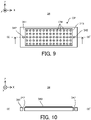
- FIG. 9 is a planar view that illustrates the calibration plate 34 on which the mark for the alignment is formed.
- FIG. 10 is a IX-IX' cross-sectional view of the calibration plate 34 illustrated in FIG. 9 .
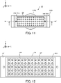
- FIG. 11 is a planar view that illustrates the calibration plate 34 that is placed on the stage 31.
- a plurality of pins 319 are formed on the stage 31 as the marks for the alignment.
- two pins 319 are formed on an upper surface (especially, an upper surface that is higher than or at the same height as an upper surface of the stage 31 ⁇ Z) of the stage 31 ⁇ X included in the stage 31.
- a formed position and the number of the pin 319 are not limited to examples illustrated in FIG. 7 and FIG. 8 .
- the pin 319 is a member that protrudes from the upper surface of the stage 31 (the upper surface of the stage 31 ⁇ X in the example illustrated in FIG. 7 and FIG. 8 ) along the Z axis direction. Note that an information related to positions of the pins 319 in the stage coordinate system is an information that is already known to the control apparatus 7.
- the calibration plate 34 includes a base member 341.
- the base member 341 is a plate-shaped member.
- the base member 341 has a shape and a size that allow it to be placed on the stage 31.
- a plurality of through-holes 342 are formed in the base member 341 as the marks for the alignment. In an example illustrated in FIG. 9 and 10 , two through-holes 342 are formed in the base member 341. The through-hole 342 penetrates the base member 341 along the Z axis direction.
- the calibration plate 34 is placed on the stage 31 so that the pins 319 are inserted into the through-holes 342.
- the calibration plate 34 is placed on the stage 31 (namely, on the stage 31 ⁇ X and the stage 31 ⁇ Z) in a state where the pins 319 are inserted into the through-holes 322.
- the stage 31 supports (for example, holds) the calibration plate 34 in a state where the pins 319 are inserted into the through-holes 322.
- an arrangement aspect of the through-holes 342 is same as an arrangement aspect of the pins 319.
- the number of the through-holes 342 is equal to (alternatively, may be more than) the number of the pins 319.
- the calibration plate 34 is placed on the stage 31 to have the desired positional relationship relative to the stage 31.
- the calibration plate 34 is placed on the stage 31 to have the desired positional relationship relative to the pins 319 on the stage 31.
- the position at which the pin 319 is formed may be used as a fiducial position on the stage 31 in placing the calibration plate 34 on the stage 31.
- the calibration plate 34 is placed on the stage 31 in a state where it is aligned to have the desired positional relationship relative to the fiducial position on the stage 31.
- a calibration pattern CP which is measurable by the measurement apparatus 4, is formed on the calibration plate 34.
- the calibration pattern CP is a measurement pattern including a plurality of calibration markers CM arranged in a matrix pattern.
- a position at which the calibration pattern CP is formed (in the example illustrated in FIG. 9 , positions at which the plurality of calibration markers CM are formed) on the calibration plate 34 is an information that is already known to the control apparatus 7.
- the position at which the calibration pattern CP is formed in the stage coordinate system is also an information that is already known to the control apparatus 7.
- thermosensitive film 343 having a thermal sensitivity (namely, sensitivity) to the processing light EL is formed on the calibration plate 34.
- a photosensitive film having a photosensitivity (namely, sensitivity) to the processing light EL may be formed on the calibration plate 34, in addition to or instead of the thermosensitive film 343.
- the thermosensitive film 343 is formed on the calibration plate 34 to cover the calibration pattern CP.
- the thermosensitive film 343 is transparent to the measurement light ML (for example, a visible light) that is used by the measurement apparatus 4.
- the calibration pattern CP covered with the thermosensitive film 343 is measurable by the measurement apparatus 4.
- the control apparatus 7 irradiates the processing unit 2 and the stage unit 3 to irradiate at least a part of the calibration plate 34 with the processing light EL (a step S12). Specifically, the control apparatus 7 changes the relative positional relationship between the processing head 21 and the stage 31 so that the target irradiation area EA moves along a predetermined moving pattern on at least a part of the thermosensitive film 343 of the calibration plate 34. Specifically, the control apparatus 7 moves the processing head 21 so that the target irradiation area EA moves along a predetermined moving trajectory on at least a part of the thermosensitive film 343 of the calibration plate 34. In this case, the control apparatus 7 may not move the stage 31.
- the control apparatus 7 irradiates the target irradiation area EA, which moves along the predetermined moving trajectory on at least a part of the thermosensitive film 343, with the processing light EL.
- FIG. 12 that is a planar view illustrating the calibration plate 34 that is irradiated with the processing light EL
- an exposed pattern PP corresponding to the moving trajectory of the target irradiation area EA is formed on at least a part of the thermosensitive film 343.
- the target irradiation area EA moves along a grid-like moving trajectory including a moving trajectory extending along each of the X axis direction and the Y axis direction between the plurality of calibration markers CM.
- the measurement apparatus 4 measures at least a part of the calibration plate 34 (a step S13). Specifically, the measurement apparatus 4 measures the exposed pattern PP formed on the thermosensitive film 343 of the calibration plate 34. Namely, the measurement apparatus 4 measures a part of the thermosensitive film 343 that is exposed by the processing light EL. Moreover, since the thermosensitive film 343 is transparent to the measurement light ML, the measurement apparatus 4 measures the calibration pattern CP as well as the exposed pattern PP. Therefore, a measured result by the measurement apparatus 4 at the step S13 includes an information related to a measured result of the exposed pattern PP and an information related to a measured result of the calibration pattern CP.
- the control apparatus 7 associates the processing coordinate system with the stage coordinate system based on the measured result by the measurement apparatus 4 at the step S13 (a step S14). Specifically, the control apparatus 7 calculates a position of the exposed pattern PP and a position of the calibration pattern CP based on the measured result by the measurement apparatus 4.
- the calibration plate 34 on which the calibration pattern CP is formed has the desired positional relationship relative to the stage ⁇ Z of the stage 31 and the position at which the calibration pattern CP is formed is the information that is already known to the control apparatus 7.
- the calculated position of the calibration pattern CP substantially corresponds to the position of the calibration pattern CP in the stage coordinate system.
- the control apparatus 7 is capable of calculating the position of the exposed pattern PP in the stage coordinate system by comparing the position of the calibration pattern CP in the stage coordinate system with the position of the exposed pattern PP. Furthermore, since the exposed pattern PP is formed by the processing light EL from the processing head 21, the position of the exposed pattern PP indirectly indicates a position of the processing head 21. Namely, the position of the exposed pattern PP indirectly indicates the position of the processing head 21 in the processing coordinate system. Thus, the control apparatus 7 is capable of associating the position of the processing head 21 in the processing coordinate system with the position of the calibration pattern CP in the stage coordinate system based on the position of the exposed pattern PP and the position of the calibration pattern CP.
- control apparatus 7 is capable of associating the processing coordinate system with the stage coordinate system.
- the position of the exposed pattern PP and the position of the calibration pattern CP may be measured by a measurement apparatus (as one example, an external measurement apparatus) that is different from the measurement apparatus 4.
- a misalignment of the processing coordinate system relative to the stage coordinate system is calculatable.
- the misalignment of the processing coordinate system relative to the stage coordinate system corresponds to a difference between an ideal (namely, a designed) position of the exposed pattern PP and the actually measured position of the exposed pattern PP.
- the misalignment of the processing coordinate system relative to the stage coordinate system may include a difference between an origin point of the stage coordinate system and an origin point of the processing coordinate system, for example.
- the misalignment of the processing coordinate system relative to the stage coordinate system may include an misalignment of a moving plane of the processing head 21 (for example, at least one of a moving plane when the processing head 21 moves along the X axis and a moving plane when the processing head 21 moves along the Y axis) relative to an axis of the stage coordinate system, for example.
- the control apparatus 7 may calculate a movement correction value that allows the processing head 21 to move so as to cancel (in other words, correct) the misalignment.
- the control apparatus 7 may calculate at least one of a movement correction value for correcting the moving direction when the processing head 21 moves along the X axis, a movement correction value for correcting the moving distance when the processing head 21 moves along the X axis, a movement correction value for correcting the moving direction when the processing head 21 moves along the Y axis and a movement correction value for correcting the moving distance when the processing head 21 moves along the Y axis.
- the control apparatus 7 may move the processing head 21 by using the movement correction value calculated by the coordinate matching operation. Namely, When the above described additive processing operation is performed, the control apparatus 7 may move the processing head 21 based on the measured result of the calibration plate 34 in the coordinate matching operation.
- the control apparatus 7 is capable of moving the processing head in a same manner as a case where there is no misalignment of the processing coordinate system relative to the stage coordinate system. Namely, as a result, even when there is the misalignment of the processing coordinate system relative to the stage coordinate system, the control apparatus 7 is capable of moving the processing head 21 so that the desired position on the workpiece W is irradiated with the processing light EL.
- the control apparatus 7 is capable of converting a certain coordinate position in either one of the e processing coordinate system and the stage coordinate system into a coordinate position in the other one of the e processing coordinate system and the stage coordinate system.
- the operation for "associating the e processing coordinate system with the stage coordinate system" may be regarded to be substantially equivalent to an operation for calculating an information (for example, a conversion matrix) that is used to convert a certain coordinate position in either one of the e processing coordinate system and the stage coordinate system into a coordinate position in the other one of the e processing coordinate system and the stage coordinate system
- the calibration plate 34 is attached to the stage 31 ⁇ X in the above described example, however, the calibration plate 34 may be attached to the stage 31 ⁇ Z.
- FIG. 13 illustrates the workpiece W that is supported by the stage 31 so that the eccentric amount ⁇ that is the amount of the misalignment between the rotational axis of the stage 31 and the ideal rotational axis of the workpiece W is zero.
- FIG. 13 to FIG. 17 omit an illustration of a holding clasp for fixing the workpiece W on the stage 31 for the purpose of simple illustration.
- the eccentric amount ⁇ means the amount of the misalignment between the rotational axis of the stage 31 ⁇ Z (in the below described description, it is referred to as a "rotational axis ⁇ Z”) and the ideal rotational axis of the workpiece W (in the below described description, it is referred to as a "rotational axis ⁇ W").
- the rotational axis ( ⁇ W may be typically an axis passing through a centroid (namely, a center of mass) of the workpiece W. In an example illustrated in FIG.
- the rotational axis ( ⁇ W of the cylindrical workpiece W extending in a direction along the rotational axis ⁇ Z is an axis passing through a center of a cylinder.
- the eccentric amount ⁇ may mean an amount of an misalignment between the rotational axis ⁇ Z and the centroid of the workpiece W.
- FIG. 14A illustrates the relative positional relationship between the processing head 21 and the workpiece W supported by the stage 31 ⁇ Z rotating around the rotational axis ⁇ Z parallel to the Z axis in a state where the eccentric amount ⁇ is zero.
- FIG. 14B illustrates the relative positional relationship between the processing head 21 and the workpiece W supported by the stage 31 ⁇ Z rotating around the rotational axis ⁇ Z inclined with respect to the Z axis in a state where the eccentric amount ⁇ is zero.
- FIG. 14B illustrates the relative positional relationship between the processing head 21 and the workpiece W supported by the stage 31 ⁇ Z rotating around the rotational axis ⁇ Z inclined perpendicular to the Z axis in a state where the eccentric amount ⁇ is zero.
- a state of the rotational axis ⁇ Z relative to the Z axis is changeable by the rotation of the stage 31 ⁇ X.
- FIG. 14A to FIG. 14C when the eccentric amount ⁇ is zero, the rotational axis ⁇ Z overlaps with (namely, is same as) the rotational axis ( ⁇ W.
- the stage 31 ⁇ Z rotates around the rotational axis ⁇ Z
- the workpiece W rotates around the rotational axis ( ⁇ W.
- the relative positional relationship between the processing head 21 and the workpiece W does not change.
- FIG. 15 illustrates the workpiece W that is supported by the stage 31 so that the eccentric amount ⁇ is not zero.
- the eccentric amount ⁇ is not zero, there is a possibility that the relative positional relationship between the processing head 21 and the workpiece W changes even in a state where the processing head 21 does not move when the stage 31 ⁇ Z rotates around the rotational axis ⁇ Z. Namely, there is a possibility that a relative positional relationship between the processing coordinate system and the workpiece W changes.
- FIG. 16A and FIG. 16B illustrate the relative positional relationship between the processing head 21 and the workpiece W supported by the stage 31 ⁇ Z rotating around the rotational axis ⁇ Z parallel to the Z axis in a state where the eccentric amount ⁇ is not zero.
- the rotational axis ⁇ Z does not overlap with (namely, is not same as) the rotational axis ( ⁇ W.
- the stage 31 ⁇ Z rotates around the rotational axis ⁇ Z
- the workpiece W rotates around the rotational axis ⁇ Z that is different from the rotational axis ( ⁇ W.
- the workpiece W is displaced relative to the processing head 21 (relative to the processing coordinate system) toward a direction based on a rotational angle of the stage 31 ⁇ Z around the rotational axis ⁇ Z by a displaced amount based on the rotational angle of the stage 31 ⁇ Z around the rotational axis ⁇ Z.
- the workpiece W is displaced relative to the processing head 21 (relative to the processing coordinate system) in a plane perpendicular to the rotational axis ⁇ Z (in an example illustrated in FIG. 16A and FIG. 16B , the XY plane).
- FIG. 17A and FIG. 17B illustrate the relative positional relationship between the processing head 21 and the workpiece W supported by the stage 31 ⁇ Z rotating around the rotational axis ⁇ Z inclined with respect to the Z axis in a state where the eccentric amount ⁇ is not zero. Even in this case, the workpiece W is displaced relative to the processing head 21 (relative to the processing coordinate system) in a plan perpendicular to the rotational axis ⁇ Z (in the example illustrated in FIG. 17A and FIG. 17B , a plane that intersects with the X axis, the Y axis and the Z axis).
- FIG. 18A and FIG. 18B illustrate the relative positional relationship between the processing head 21 and the workpiece W supported by the stage 31 ⁇ Z rotating around the rotational axis ⁇ Z perpendicular to the Z axis in a state where the eccentric amount ⁇ is not zero. Even in this case, the workpiece W is displaced relative to the processing head 21 (relative to the processing coordinate system) in a plan perpendicular to the rotational axis ⁇ Z (in the example illustrated in FIG. 18A and FIG. 18B , the XZ plane).
- the processing system SYSa obtains the eccentric amount ⁇ by the eccentric amount obtaining operation and processes the workpiece W by using the obtained eccentric amount ⁇ in performing the additive processing operation (namely, during the processing of the workpiece W, during the irradiation of the processing light EL). Specifically, the processing system SYSa rotates the stage 31 (for example, at least one of the stage 31 ⁇ X and the stage 31 ⁇ Z) and moves the processing head 21 based on the obtained eccentric amount ⁇ . Namely, the processing system SYSa moves the processing head 21 in parallel with the rotation of the stage 31 based on the obtained eccentric amount ⁇ .
- the processing system SYSa rotates the stage 31 based on the eccentric amount ⁇ and moves the processing head 21 based on the eccentric amount ⁇ so as to reduce (typically, cancel, the same is applied to the below described description) an influence of the displacement of the workpiece W relative to the processing head 21 due to the rotation of the stage 31.
- the workpiece W is displaced relative to the processing head 21 (relative to the processing coordinate system) in the plane perpendicular to the rotational axis ⁇ Z due to the rotation of the stage 31.
- the processing system SYSa may move the processing head 21 in the plane perpendicular to the rotational axis ⁇ Z based on the eccentric amount ⁇ so that the desired position on the workpiece W is irradiated with the processing light EL even when the workpiece W is displaced relative to the processing head 21 due to the rotation of the stage 31.
- the processing head 21 when the workpiece W is displaced relative to the processing head 21 (relative to the processing coordinate system) in the XY plane as illustrated in FIG. 16A and FIG.
- the processing system SYSa may move the processing head 21 in the XY plane so that the desired position on the workpiece W is irradiated with the processing light EL even when the workpiece W is displaced relative to the processing head 21 due to the rotation of the stage 31.
- the processing system SYSa may move the processing head 21 along at least one of the X axis direction and the Y axis direction. For example, when the workpiece W is displaced relative to the processing head 21 (relative to the processing coordinate system) in the plane that intersects with the X axis, the Y axis and the Z axis (namely, a plane that is inclined with respect to the moving direction of the processing head 21) as illustrated in FIG. 17A and FIG.
- the processing system SYSa may move the processing head 21 in the plane that intersects with the X axis, the Y axis and the Z axis so that the desired position on the workpiece W is irradiated with the processing light EL even when the workpiece W is displaced relative to the processing head 21 due to the rotation of the stage 31.
- the processing system SYSa may move (namely, move up and down) the processing head 21 along the Z axis direction and may move the processing head 21 along at least one of the X axis direction and the Y axis direction.
- the workpiece W is displaced relative to the processing head 21 (relative to the processing coordinate system) in the XZ plane as illustrated in FIG. 18A and FIG.
- the processing system SYSa may move the processing head 21 in the XZ plane so that the desired position on the workpiece W is irradiated with the processing light EL even when the workpiece W is displaced relative to the processing head 21 due to the rotation of the stage 31.
- the processing system SYSa may move (namely, may move up and down) the processing head 21 along the Z axis direction.
- the processing system SYSa is capable of irradiating the desired position on the workpiece W with the processing light EL by moving the processing head 21 even when the workpiece W is displaced relative to the processing head 21 (relative to the processing coordinate system) due to the rotation of the stage 31 ⁇ Z.
- the processing system SYSa is capable of irradiating the desired position on the workpiece W with the processing light EL without performing an strict alignment of the workpiece W on the rotating stage 31.
- the processing system SYSa may use a measured result by the position measurement device 33 that measures the position of the stage 31. For example, the processing system SYSa may calculate the rotational angle of the stage 31 ⁇ Z around the rotational axis ⁇ Z based on the measured result by the position measurement device 33 and may move the processing head 21 based on the calculated rotational angle.
- the processing system SYSa may move the stage 31 in addition to or instead of the processing head 21 so that the desired position on the workpiece W is irradiated with the processing light EL even when the workpiece W is displaced relative to the processing head 21 due to the rotation of the stage 31.
- the processing system SYSa may move the workpiece W in addition to or instead of the processing head 21 by considering the displacement of the workpiece W relative to the processing head 21 due to the rotation of the stage 31.
- the processing system SYSa may move the irradiation position change optical member in addition to or instead of the processing head 21 by considering the displacement of the workpiece W relative to the processing head 21 due to the rotation of the stage 31.
- the irradiation position change optical member there is a Galvano mirror 2111 as illustrated in FIG. 19 that illustrates a configuration of the irradiation optical system 211.
- the processing system SYSa may move the Galvano mirror 2111 (specifically, may control the movement of the Galvano mirror 2111) by considering the displacement of the workpiece W relative to the processing head 21 due to the rotation of the stage 31.
- the irradiation position change optical member there is a polygonal mirror.
- FIG. 20 is a flowchart that illustrates the flow of the eccentric amount obtaining operation.
- the control apparatus 7 calculates the rotational axis of the stage 31 (the rotational axis ⁇ Z of the stage 31 ⁇ Z in the first example embodiment) by using the measured result of the stage 31 by the measurement apparatus 4 (a step S21). Note that a detailed description of an operation for calculating the rotational axis ⁇ Z will be described later in detail with reference to FIG. 21 . Furthermore, the control apparatus 7 calculates the rotational axis ( ⁇ W of the workpiece W by using the measured result of the workpiece W by the measurement apparatus 4 before or after the step S21 (a step S22). Note that a detailed description of an operation for calculating the rotational axis ( ⁇ W will be described later in detail with reference to FIG. 22 . Then, the control apparatus 7 calculates the eccentric amount ⁇ based on the rotational axis ⁇ Z calculated at the step S21 and the rotational axis ( ⁇ W calculated at the step S22 (a step S23).
- the rotational axis ⁇ Z calculated at the step S21 is an information unique to the position of the stage 31.
- the rotational axis ⁇ Z calculated at the step S21 is one specific example of a stage position information related to the position of the stage 31.
- the control apparatus 7 may calculate any stage position information related to the position of the stage 31 in addition to or instead of the rotational axis ⁇ Z by using the measured result of the stage 31 by the measurement apparatus 4. Then, the control apparatus 7 may calculate the eccentric amount ⁇ based on the stage position information.
- the step S21 may not be performed.
- the rotational axis ( ⁇ W calculated at the step S22 is an information unique to the position of the workpiece W.
- the rotational axis ( ⁇ W calculated at the step S2w is one specific example of a workpiece position information related to the position of the workpiece W.
- the control apparatus 7 may calculate any workpiece position information related to the position of the workpiece W in addition to or instead of the rotational axis ⁇ W by using the measured result of the workpiece W by the measurement apparatus 4. Then, the control apparatus 7 may calculate the eccentric amount ⁇ based on the workpiece position information.
- the eccentric amount ⁇ calculated at the step S23 is one specific example of a positional relationship information related to the positional relationship between the rotational axis ⁇ Z of the stage 31 ⁇ Z and the workpiece W.
- the eccentric amount ⁇ calculated at the step S23 is one specific example of the positional relationship information related to the positional relationship between the stage 31 and the workpiece W.
- the control apparatus 7 may calculate any positional relationship information related to the positional relationship between the rotational axis ⁇ Z of the stage 31 ⁇ Z and the workpiece W in addition to or instead of the eccentric amount ⁇ .
- the processing system SYSa may move the processing head 21 based on any positional relationship information by considering the displacement of the workpiece W relative to the processing head 21 due to the rotation of the stage 31.
- FIG. 21 is a flowchart that illustrates the flow of the operation for calculating the rotational axis ⁇ Z of the stage 31 ⁇ Z at the step S21 in FIG. 20 .
- the control apparatus 7 calculates the rotational axis ⁇ Z of the stage 31 ⁇ Z by using the measured result of the stage 31 by the measurement apparatus 4.
- the measurement apparatus 4 measures at least a part of the calibration plate 34 placed on the stage 31 instead of directly measuring at least a part of the stage 31 in order to easily calculating the rotational axis ⁇ Z from the measured result by the measurement apparatus 4.
- the measurement apparatus 4 indirectly measures at least a part of the stage 31 by measuring at least a part of the calibration plate 34 placed on the stage 31.
- the measurement apparatus 4 may directly measure at least a part of the stage 31.
- the measurement apparatus 4 may directly measure at least a part of the stage 31 (for example, a part on which the calibration pattern CP is formed).
- the calibration plate 34 is placed on the stage 31 ⁇ Z of the stage 31 (a step S210). Even in the eccentric amount obtaining operation, the calibration plate 34 may be placed on the stage 31 so that the positional relationship between the calibration plate 34 and the stage 31 ⁇ Z of the stage 31 is the desired positional relationship, as with the coordinate matching operation. However, the thermosensitive film 343 may not be formed on the calibration plate 34 placed on the stage 31 in the eccentric amount obtaining operation. Note that another calibration plate on which a desired calibration pattern CP is formed may be placed on the stage 31 instead of the calibration plate 34.
- the control apparatus 7 controls the stage driving system 32 so that the stage 31 is located at an origin point position (a step S211).
- the origin point position may be a position at which the rotational angle measured by the position measurement device 33 is zero.
- the measurement apparatus 4 measures at least a part of the calibration plate 34 (a step S212). Specifically, the measurement apparatus 4 measures the calibration pattern CP formed on the calibration plate 34.
- the control apparatus 7 determines whether or not the measurement of the calibration plate 34 should be ended (a step S213). For example, the control apparatus 7 may determine that the measurement of the calibration plate 34 should be ended when the measurement apparatus 4 measures the calibration plate 34 by a first desired number of times. It is preferable that the first desired number of times be at least two times.
- the control apparatus 7 rotates the stage 31 ⁇ Z around the rotational axis ⁇ Z by a first desired angle (step S214).
- the first desired angle may be any angle smaller than 360 degree.
- the first desired angle may be any angle that is different from a multiple of 360 degree.
- the measurement apparatus 4 measures the calibration plate 34 again (the step S212). Namely, in the first example embodiment, the measurement apparatus 4 measures the calibration plate 34 each time the stage 31 rotates.
- the measurement apparatus 4 measures the calibration plate 34 a plurality of times from different directions.
- the measurement apparatus 4 measures the calibration plate 34 in different attitudes a plurality of times.
- the control apparatus 7 calculates the rotational axis ⁇ Z of the stage 31 ⁇ Z by using the measured result of the calibration plate 34 by the measurement apparatus 4 at the step S212 (a step S215).
- the control apparatus 7 is capable of calculating the position of the calibration pattern CP based on the measured result of the calibration plate 34.
- the position of the calibration pattern CP substantially corresponds to the position of the stage 31 supporting the calibration plate 34. Therefore, the control apparatus 7 may be regarded to indirectly calculate the position of the stage 31 by calculating the position of the calibration pattern CP.
- the measurement apparatus 4 may be regarded to indirectly measure the position of the stage 31 by measuring the position of the calibration pattern CP.
- the control apparatus 7 calculates the position of the calibration pattern CP as many times as the stage 31 ⁇ Z rotates. Namely, the control apparatus 7 calculates the position of the calibration pattern CP for each rotating angle of the stage 31 ⁇ Z during the measurement of the calibration plate 34. Then, the control apparatus 7 performs a fitting of the position of the calibration pattern CP calculated for each rotating angle of the stage 31 ⁇ Z by a circle. Then, the control apparatus 7 calculates, as the rotational axis ⁇ Z of the stage 31 ⁇ Z, an axis that passes through a center of the circle obtained by the fitting and that is perpendicular to the circle.
- control apparatus 7 may calculates the rotational axis of the stage 31 ⁇ X by performing an operation that is same as the operation illustrated in FIG. 21 .
- FIG. 22 is a flowchart that illustrates the flow of the operation for calculating the rotational axis ⁇ W of the workpiece W at the step S22 in FIG. 20 .
- the measurement apparatus 4 measures at least a part of the workpiece W (a step S222).
- the control apparatus 7 determines whether or not the measurement of the workpiece W should be ended (a step S223). For example, the control apparatus 7 may determine that the measurement of the workpiece W should be ended when the measurement apparatus 4 measures the workpiece W by a second desired number of times. It is preferable that the second desired number of times be at least two times.
- the control apparatus 7 rotates the stage 31 ⁇ Z around the rotational axis ⁇ Z by a second desired angle (step S224).
- the second desired angle may be any angle smaller than 360 degree.
- the second desired angle may be any angle that is different from a multiple of 360 degree.
- the measurement apparatus 4 measures the workpiece W again (the step S211). Namely, in the first example embodiment, the measurement apparatus 4 measures the workpiece W each time the stage 31 rotates.
- the measurement apparatus 4 measures the workpiece W a plurality of times from different directions.
- the measurement apparatus 4 measures the workpiece W in different rotational attitudes a plurality of times.
- the control apparatus 7 calculates the rotational axis ⁇ W of the workpiece W by using the measured result of the workpiece W by the measurement apparatus 4 at the step S222 (a step S225). Specifically, the control apparatus 7 generates an information related to a position and / or a shape of a part of the workpiece W in a certain rotational attitude included in a measurement range of the measurement apparatus 4 based on the measured result of the workpiece W in a certain rotational attitude.
- control apparatus 7 may generate a point cloud information related to a plurality of points constituting a part of the surface of the workpiece W in a certain rotational attitude included in the measurement range of the measurement apparatus 4 based on the measured result of the workpiece W in a certain rotational attitude.
- the control apparatus 7 repeats an operation for generating the information related to the position and / or the shape of at least a part of the workpiece W as many times as the workpiece W is measured. Then, the information related to the position and / or the shape of at least a part of the workpiece W is merged based on the rotational attitude of the workpiece W.
- the control apparatus 7 may generate a fist point cloud information from the measured result of the workpiece W in a first rotational attitude, generate a second point cloud information from the measured result of the workpiece W in a second rotational attitude, and merge the first and second point cloud information based on the first and second rotational attitudes.
- an area a presence of which is indicated by the point cloud information is larger on the surface of the workpiece W. In other words, there is a higher possibility that the control apparatus 7 is capable of recognizing whole of the workpiece W.
- the control apparatus 7 may control the measurement apparatus 4 to newly measure this part, and may further merge the measured result by the measurement apparatus 4 with the merged point cloud information. Then, the control apparatus 7 calculates the rotational axis ⁇ W of the workpiece W based on the merged point cloud information. For example, when a three-dimensional model (for example, a design information) of the workpiece W can be obtained, the control apparatus 7 may perform a fitting of the three-dimensional model of the workpiece W on the merged point cloud information, and may calculate the rotational axis ⁇ W of the workpiece W based on the three-dimensional model on which the fitting is already performed.
- a three-dimensional model for example, a design information
- control apparatus 7 may generate a surface model (alternatively, a solid model) of the workpiece W based on the merged point cloud information, and may calculate the rotational axis ⁇ W of the workpiece W based on the surface model (alternatively, the solid model).
- the control apparatus 7 obtains a plurality of measured results obtained by measuring the calibration plate 34 a plurality of times from different directions, and calculates the rotational axis ⁇ Z of the stage 31 based on the plurality of measured results at the step S21 in FIG. 20 . Furthermore, the control apparatus 7 obtains a plurality of measured results obtained by measuring the workpiece W a plurality of times from different directions, and calculates the rotational axis ⁇ W of the workpiece W based on the plurality of measured results at the step S22 in FIG. 20 . Furthermore, the control apparatus 7 calculates the eccentric amount ⁇ based on the calculated rotational axes ⁇ Z and ⁇ W.
- control apparatus 7 may be regarded to serve as a measurement apparatus or an arithmetic apparatus that includes: a measurement part that is configured to obtain a first measured result of the workpiece W measured from a first direction (namely, the workpiece W in a first rotational attitude) and a second measured result of the workpiece W measured from a second direction (namely, the workpiece W in a second rotational attitude); and a relationship obtaining part that is configured to obtain the eccentric amount ⁇ (namely, a relationship between the rotational axis ⁇ Z and the workpiece W) based on the first and second measured results.
- a measurement part that is configured to obtain a first measured result of the workpiece W measured from a first direction (namely, the workpiece W in a first rotational attitude) and a second measured result of the workpiece W measured from a second direction (namely, the workpiece W in a second rotational attitude)
- a relationship obtaining part that is configured to obtain the eccentric amount ⁇ (namely, a relationship between the rotational axis ⁇ Z
- the eccentric amount ⁇ corresponds to a translational movement component, in which a rotational movement component is removed, of a movement component of one point of the workpiece W when the stage 31 ⁇ Z is rotated (namely, the workpiece W is rotated) in the eccentric amount obtaining operation.
- control apparatus 7 may be regarded to serve as a measurement apparatus or an arithmetic apparatus that includes: the measurement part that is configured to obtain the first measured result of the workpiece W measured from the first direction (namely, the workpiece W in the first rotational attitude) and the second measured result of the workpiece W measured from the second direction (namely, the workpiece W in the second rotational attitude); and a difference obtaining part that is configured to obtain the translational movement component, in which the rotational movement component is removed, of the movement component of one point of the workpiece W when the stage 31 ⁇ Z is rotated (namely, the workpiece W is rotated) in the eccentric amount obtaining operation.
- control apparatus 7 calculates the rotational axis ⁇ W of the workpiece W from the point cloud information here, however, the control apparatus 7 may calculate any information related to the position of the workpiece W from the point cloud information.
- the processing system SYSa in the first example embodiment is capable of rotating the stage 31 and moving the processing head 21 by considering the displacement of the workpiece W relative to the processing head 21 due to the rotation of the stage 31 based on the eccentric amount ⁇ obtained from the measured result by the measurement apparatus 4.
- the processing system SYSa is capable of irradiating the desired position on the workpiece W with the processing light EL.
- the processing system SYSa is capable of properly processing the workpiece W.
- the processing system SYSa is capable of processing the workpiece W with a small processing error.
- the processing system SYSb in the second example embodiment is different from the processing system SYSa in the first example embodiment in that it may perform a removal processing for removing a part of the workpiece W by irradiating the workpiece W with the processing light EL.
- the processing system SYSb may perform the removal processing so that the shape of the workpiece W is a desired shape.
- the processing system SYSb may perform the removal processing to form a desired structure on the workpiece W.
- the processing system SYSb may perform the removal processing to form a desired structure on the surface of the workpiece W.
- the processing system SYSb may perform the removal processing so that the surface of the workpiece W is polished.
- the processing system SYSb may form a riblet structure on the workpiece W.
- the riblet structure may be a structure by which a resistance (especially, a frictional resistance, a turbulent frictional resistance) of the surface of the workpiece W to a fluid is reducible.
- the riblet structure may be a structure by which a noise generated when the fluid and the surface of the workpiece W relatively moves is reducible.
- the riblet structure include a structure in which a plurality of grooves each of which extends along a first direction (the Y axis direction) along the surface of the workpiece W are arranged along a second direction (the X axis direction) that is along the surface of the workpiece W and that intersects with the first direction, for example.
- the processing system SYSb may form any structure having any shape on the surface of the workpiece W.
- a structure that generates a swirl relative to a flow of the fluid on the surface of the workpiece W is one example of any structure.
- a structure that add a hydrophobic property to the surface of the workpiece W is one example of any structure.
- a fine texture structure (typically, a concave and convex structure) that is formed regularly or irregularly in a micro / nano-meter order is another example of any structure. This fine texture structure may include at least one of a shark skin structure or a dimple structure that has a function of reducing a resistance from a fluid (a liquid and / or a gas).
- the fine texture structure may include a lotus leaf surface structure that has at least one of a liquid repellent function and a self-cleaning function (for example, has a lotus effect).
- the fine texture structure may include at least one of a fine protrusion structure that has a liquid transporting function ( US2017/0044002A1 ), a concave and convex structure that has a lyophile effect, a concave and convex structure that has an antifouling effect, a moth eye structure that has at least one of a reflectance reduction function and a liquid repellent function, a concave and convex structure that intensifies only light of a specific wavelength by interference to have a structural color, a pillar array structure that has an adhesion function using van der Waals force, a concave and convex structure that has an aerodynamic noise reduction function, a honeycomb structure that has a droplet collection function and so on.
- FIG. 23 and FIG. 24 illustrates the processing system SYSb.
- FIG. 23 is a block diagram that illustrates a system configuration of the processing system SYSb.
- FIG. 24 is a cross-sectional view that illustrates a configuration of the processing system SYSb.
- the processing system SYSb is different from the processing system SYSa in that it may not include the material supply source 1 and mix apparatus 12.
- the processing system SYSb is different from the processing system SYSa in that it may not include the material nozzle 212.
- the processing system SYSb is different from the processing system SYSa in that it includes a processing unit 2b including a processing head 21b that does not include the material nozzle 212 instead of the processing unit 2 including the processing head 21 that includes the material nozzle 212.
- the processing system SYSb is different from the processing system SYSa in that it may not include a component for supplying the build materials M.
- Another feature of the processing system SYSb may be same as another feature of the processing system SYSa.
- the above described processing system SYSb may also move at least one of the processing head 21b and the stage 31 based on the results of the coordinate matching operation and the eccentric amount obtaining operation in processing (namely, performing the removal processing on) the workpiece W.
- the processing system SYSb may rotate the stage 31 and move the processing head 21b (furthermore, the stage 31) based on the result of the eccentric amount obtaining operation while irradiating the workpiece W with the processing light EL.
- the processing system SYSb is capable of achieving an effect that is same as the effect achievable by the processing system SYSa.
- the processing system SYSb may change the irradiation position of the processing light EL by the irradiation position change optical member, instead of moving the processing head 21.
- the processing system SYSb may change the irradiation position of the processing light EL based on the eccentric amount ⁇ obtained from the measured result by the measurement apparatus 4.
- the processing system SYSb may irradiate the workpiece W with the processing light EL including the plurality of pulsed lights.
- the processing system SYSb may irradiate the workpiece W with the processing light EL including the plurality of pulsed lights the ON time of each of which is equal to or shorter than nano seconds.
- the processing system SYSc in the third example embodiment is different from the processing system SYSa in the first example embodiment in that it may process the workpiece W by using a tool 215c (see FIG. 25 described later and FIG. 21 ) for machining the workpiece W in addition to or instead of the processing light EL.
- the processing system SYSc is different from the processing system SYSa in that it may perform a machining processing the workpiece W.
- the processing system SYSc may perform a cutting processing, a grinding processing, a polishing processing or a cutting-off processing on the workpiece W by making the tool contact with the workpiece W.
- the processing system SYSb may perform the machining processing on the workpiece W so that the shape of the workpiece W is a desired shape.
- the processing system SYSb may perform the machining processing on the workpiece W to form a desired structure on the workpiece W.
- the processing system SYSb may perform the machining processing on the workpiece W to form a desired structure on the surface of the workpiece W.
- the processing system SYSb may perform the machining processing on the workpiece W so that the surface of the workpiece W is polished.
- FIG. 25 and FIG. 26 illustrates the processing system SYSc.
- FIG. 25 is a block diagram that illustrates a system configuration of the processing system SYSc.
- FIG. 26 is a cross-sectional view that illustrates a configuration of the processing system SYSc.
- the processing system SYSc is different from the processing system SYSa in that it may not include the light source 5.
- the processing system SYSc is different from the processing system SYSa in that it may not include the irradiation optical system 211.
- the processing system SYSc is different from the processing system SYSa in that it includes a processing unit 2c including a processing head 21c that does not include the irradiation optical system 211 instead of the processing unit 2 including the processing head 21 that includes the irradiation optical system 211.
- the processing system SYSc is different from the processing system SYSa in that it may not include a component for irradiating the workpiece W with the processing light EL.
- the processing system SYSc is different from the processing system SYSa in that it may not include the component for supplying the build materials M.
- the processing system SYSc is different from the processing system SYSa in that it includes the processing head 21c that includes the tool 215c instead of the processing head 21. Another feature of the processing system SYSc may be same as another feature of the processing system SYSa.
- the above described processing system SYSc may also move at least one of the processing head 21c and the stage 31 based on the results of the coordinate matching operation and the eccentric amount obtaining operation in processing (namely, performing the removal processing on) the workpiece W.
- the processing system SYSb may rotate the stage 31 and move the processing head 21 (furthermore, the stage 31) based on the result of the eccentric amount obtaining operation in while making the tool 215c contact with the workpiece W.
- the processing system SYSc is capable of achieving an effect that is same as the effect achievable by the processing system SYSa.
- FIG. 27 is a block diagram that illustrates a system configuration of the processing system SYSd.
- the processing system SYSd in the fourth example embodiment is different from the processing system SYSa in that it includes a cooling apparatus 9d.
- Another feature of the processing system SYSd may be same as another feature of the processing system SYSa.
- the cooling apparatus 9d is an apparatus that is configured to cool the stage 31 (the stage 31 ⁇ Z in the fourth example embodiment) on which the workpiece W is placed. Specifically, the workpiece W placed on the stage 31 ⁇ Z is irradiated with the processing light EL. When the workpiece W is irradiated with the processing light EL, a heat is transferred from the processing light to the workpiece W. When the heat is transferred to the workpiece W, a heat is transferred from the workpiece W to the stage 31 ⁇ Z on which the workpiece W is placed. As a result, there is a possibility that a temperature of the stage 31 ⁇ Z is relatively high.
- the cooling apparatus 9d cools the stage 31 ⁇ Z the temperature of which may be possibility relatively high. Incidentally, since the stage 31 ⁇ Z is contained in the inner space of housing 8, the cooling apparatus 9d is also contained in the inner space of the housing 8.
- the cooling apparatus 9d may an air-cooled type of cooling apparatus.
- the cooling apparatus 9d may cool the stage 31 ⁇ Z by supplying a gas to the stage 31 ⁇ Z.
- the cooling apparatus 9d may cool the stage 31 ⁇ Z by supplying the gas to a space facing the stage 31 ⁇ Z.
- the cooling apparatus 9d may cool the stage 31 ⁇ Z by forming a flow of the gas in the space facing the stage 31 ⁇ Z.
- FIG. 28 is a cross-sectional view that illustrates one example of a configuration of the cooling apparatus 9d.
- the cooling apparatus 9d may cool the stage 31 ⁇ Z by supplying the gas to a lower surface 312 (namely, a surface opposite to an upper surface 311) of the stage 31 ⁇ Z having the upper surface 311 on which the workpiece W is placed. Namely, the cooling apparatus 9d may cool the stage 31 ⁇ Z by supplying the gas to a space SP1 facing the lower surface 312 of the stage 31 ⁇ Z. The lower surface 312 of the stage 31 ⁇ Z facing the stage 31 ⁇ X. Thus, the space SP1 may include at least a part of a space between the lower surface 312 of the stage 31 ⁇ Z and the stage 31 ⁇ X. However, the cooling apparatus 9d may cool the stage 31 ⁇ Z by supplying the gas to a space facing a surface that is different from the lower surface 312 of the stage 31 ⁇ Z.
- the cooling apparatus 9d may supply the gas to the space SP1 from below the stage 31 ⁇ Z.
- the gas is supplied from below the stage 31 ⁇ Z to the space SP1 facing the lower surface 312 of the stage 31 ⁇ Z, there is a low possibility that the flow of the gas is formed in a space facing the upper surface 311 of the stage 31 ⁇ Z (namely, a space facing the workpiece W).
- the build materials M supplied to the workpiece W placed on the upper surface 311 is less likely to be blown away by the gas for cooling the stage 31 ⁇ Z. Therefore, the material nozzle 212 is capable of supplying the build materials M to the workpiece W without being affected by the gas for colling the stage 31 ⁇ Z.
- the cooling apparatus 9d may supply the gas to the space SP1 through an inside of the stage 31 ⁇ X.
- the cooling apparatus 9d may supply the gas to the space SP1 through a supply path that is formed in the inside of the stage 31 ⁇ X.
- a supply path in other words, a supply space
- SP2 for supplying the gas to the space SP1 may be formed in an inside of a housing 313d of the stage 31 ⁇ X.
- the supply path SP2 is connected to an aperture 314d formed at the housing 313d to take the gas from an outside of the housing 313d to the inside of the housing 313d (especially, the supply path SP2).
- the cooling apparatus 9d may include a fan 91d disposed at the aperture 314d.
- the fan 91d is configured to be driven to take the gas from the outside of the housing 313d to the inside of the housing 313d (especially, the supply path SP2).
- the supply path SP2 is connected to an aperture 315d formed at the housing 313d to supply the gas from the supply path SP2 in the inside of the housing 313d to the space SP1 at the outside of the housing 313d.
- the aperture 315d is formed at a part (for example, a part located below the stage 31 ⁇ Z) of the housing 8 facing the space SP1.
- the cooling apparatus 9d takes the gas from the outside of the housing 313d to the supply path SP2 through the fan 91d disposed at the aperture 314d, and supplies the taken gas to the space SP1 through the supply path SP2 and the aperture 315d.
- the flow of the gas is formed in the space SP1 and stage 31 ⁇ Z is cooled by the flow of the gas.
- the gas supplied to the space SP1 in this case may include at least a part of the purge gas supplied from the gas supply source 6 to an inside of the housing 8.
- a containing space SP3 in which the motor 322 ⁇ Z, which is configured to serve as a rotation mechanism (a movement mechanism) for rotating the stage 31 ⁇ Z, may be formed in the housing 313 of the stage 31 ⁇ X.
- a force generated by the motor 322 ⁇ Z is transmitted to the stage 31 ⁇ Z through the rotational shaft 321 ⁇ Z, which is a force transmission mechanism (a movement mechanism) connected to the stage 31 ⁇ Z, and a belt 323 ⁇ Z, which is a force transmission mechanism (a movement mechanism) connecting a rotational axis of the motor 322 ⁇ Z to the rotational shaft 321 ⁇ Z.
- the rotational shaft 321 ⁇ Z and the belt 323 ⁇ Z may be contained in the containing space SP3.
- the containing space SP3 may be spatially separated from the supply path SP2 by a wall member 36d.
- the containing space SP3 is spatially separated from the supply path SP2 by the wall member 36d, it is prevented that the build materials M enter the containing space SP3 (as a result, the motor 322 ⁇ Z and so on is contaminated by the build materials M).
- the rotational axis of the motor 322 ⁇ Z may be directly connected to the rotational shaft 321 ⁇ Z.
- the stage 31 ⁇ X may be connected to the rotational shaft 321 ⁇ X through a reducer 324d.
- the reducer 324 may connect a lower surface of the stage 31 ⁇ X to the rotational shaft 321 ⁇ X.
- the reducer 324d may also be cooled by the flow of the gas for cooling the stage 31 ⁇ Z.
- the cooling apparatus 9d may include a wind guide member 92d.
- the wind guide member 92d may be configured to return the gas, which flows from the space SP1 to the outside of the space SP1, to the space SP1.
- an efficiency of cooling the stage 31 ⁇ Z is higher, compared to a case where the cooling apparatus 9d does not include the wind guide member 92d.
- the processing system SYSd is capable of cooling the stage 31 (for example, the stage 31 ⁇ Z) on which the workpiece W is placed while achieving an effect that is same as the effect achievable by the processing system SYSa.
- At least one of the processing system SYSb in the second example embodiment and the processing system SYSc in the third example embodiment may include the cooling apparatus 9d.
- thermosensitive film 343 formed on the calibration plate 34 is transparent to the measurement light ML of the measurement apparatus 4. However, at least a part of the thermosensitive film 343 may be opaque to the measurement light ML of the measurement apparatus 4.
- thermosensitive film 343 When the thermosensitive film 343 is opaque, the thermosensitive film 343 may cover whole of the calibration pattern CP as illustrated in FIG. 29 that is a planar view illustrating one example of the calibration plate 34.
- the processing system SYS may irradiate the thermosensitive film 343 with the processing light EL (the step S12 in FIG. 6 ), then, measure the exposed pattern PP by measuring the calibration plate 34 on which the thermosensitive film 343 is formed (the step S13 in FIG. 6 ), then, measure the calibration pattern CP by measuring the calibration plate 34 from which the thermosensitive film 343 is removed after the thermosensitive film 343 is removed (the step S13 in FIG. 6 ), and then, associate the processing coordinate system with the stage coordinate system by merging the measured result of the exposed pattern PP and the measured result of the calibration pattern CP.
- thermosensitive film 343 may cover a part of the calibration pattern CP as illustrated in FIG. 30 that is a planar view illustrating one example of the calibration plate 34. Namely, another part of the calibration pattern CP may not be covered with the thermosensitive film 343.
- the processing system SYS may irradiate the thermosensitive film 343 with the processing light EL (the step S12 in FIG. 6 ), then, measure the exposed pattern PP and a part of the calibration pattern CP by measuring the calibration plate 34 on which the thermosensitive film 343 is formed (the step S13 in FIG.
- the processing system SYS is capable of merging the measured result of the exposed pattern PP and the measured result of the calibration pattern CP with relatively high accuracy by using a measured result of a part of the calibration pattern CP that is included in both of the measured result of the exposed pattern PP and the measured result of the calibration pattern CP (namely, a part of the calibration pattern CP that is not covered with the thermosensitive film 343).
- the thermosensitive film 343 may cover a part of the calibration pattern CP and may not cover another part of the calibration pattern CP.
- thermosensitive film 343 may not cover the calibration pattern CP as illustrated in FIG. 31 that is a planar view illustrating one example of the calibration plate 34. Namely, the thermosensitive film 343 may be formed on a first part of the base member 341 and the calibration pattern CP may be formed on a second part of the base member 341. Incidentally, even when the thermosensitive film 343 is transparent, the thermosensitive film 343 may not cover the calibration pattern CP.
- the calibration pattern CP is formed on the calibration plate 34.
- the calibration pattern CP may be formed on a member that is different from the calibration plate 34.
- the calibration pattern CP may be formed on a member (for example, a fiducial member) that is placed on the stage 31 and that is different from the workpiece W.
- the calibration pattern CP may be formed on the stage 31.
- FIG. 32 to FIG. 34 illustrate an example in which the calibration pattern CP is formed on the stage 31 ⁇ Z, however, the calibration pattern CP may be formed on the stage 31 ⁇ X.
- FIG. 32 to FIG. 34 illustrate an example in which the calibration pattern CP is formed on the stage 31 ⁇ Z, however, the calibration pattern CP may be formed on the stage 31 ⁇ X.
- FIG. 32 illustrates an example in which the calibration pattern CP is formed on the upper surface 311 (namely, a surface on which the workpiece W is placed) of the stage 31 ⁇ Z.
- FIG. 33 illustrates an example in which the calibration pattern CP is formed on a surface (for example, an outer surface located at an outside of a holding surface 3111), which is different from the holding surface 3111 that faces the workpiece W to actually hold the workpiece W, of the upper surface 311 of the stage 31 ⁇ Z.
- FIG. 34 illustrates an example in which the calibration pattern CP is formed on a side surface 316 of the stage 31 ⁇ Z.
- the processing system SYS is capable of performing each of the coordinate matching operation and the eccentric amount obtaining operation in a state where the workpiece W is placed on the stage 31 ⁇ Z. Furthermore, when the calibration pattern CP is formed on a surface of the stage 31 ⁇ Z that is different from the holding surface 3111, the processing system SYS is capable of measuring both of at least a part of the calibration pattern CP and at least a part of the workpiece W at the same time in the eccentric amount obtaining operation.
- the processing system SYS is capable of measuring at least a part of the calibration pattern CP of the stage 31 together with at least a part of the workpiece W.
- the measurement of the calibration pattern CP by the measurement apparatus 4 to calculate the rotational axis ⁇ Z of the stage 31 ⁇ Z and the measurement of the workpiece W by the measurement apparatus 4 to calculate the rotational axis ⁇ W of the workpiece W may not be performed separately.
- a time necessary for the eccentric amount obtaining operation is reducible.
- the calibration pattern CP may include a pattern that is configured to determine the position of at least one of the stages 31 ⁇ X and 31 ⁇ Z.
- the calibration pattern CP may include an encoder pattern (for example, a grid pattern).
- the encoder pattern may be an absolute pattern.
- the measurement apparatus 4 may measure the calibration pattern CP on the stage 31 in a state where the workpiece W is placed on the stage 31.
- An existing structural object formed at the stage 31 may be used as at least a part of the calibration pattern CP in addition to or instead of the dedicated calibration pattern CP.
- a concave part for example, an aperture such as a screw hole
- a convex part for example, a protruding object
- the measurement apparatus 4 may measure the existing structural object used as at least a part of the calibration pattern CP in a state where the workpiece W is placed on the stage 31.
- the processing system SYS obtains (namely, calculates) the rotational axis ⁇ Z by measuring the calibration pattern CP.
- the processing system SYS may obtain a rotational axis ⁇ by measuring at least a part of the calibration pattern CP.
- the processing system SYS obtains the rotational axis ⁇ Z ( ⁇ X) by measuring the calibration pattern CP.
- the processing system SYS may obtain the rotational axis ⁇ Z by measuring at least a part of the stage 31 (the stage 31 ⁇ Z).
- the processing system SYS may perform a coordinate matching between a measured result of a three-dimensional shape of the stage 31 (the stage 31 ⁇ Z) and a designed model of the stage 31 (the stage 31 ⁇ Z) that is prepared in advance in a measurement coordinate system and may set a rotational axis of the designed model in the measurement coordinate system to be the rotational axis (for example, the rotational axis ⁇ Z) that should be obtained.
- the processing system SYS obtains the rotational axis ⁇ Z ( ⁇ X). However, the processing system SYS may not obtain the rotational axis ⁇ Z ( ⁇ X).
- the processing system SYS may measure three-dimensional shapes of at least a part of the stage 31 and at least a part of the workpiece W in a state where the workpiece W is placed on the stage 31, and perform a matching of a measured point cloud information of the stage 31 and the measured point cloud information of the workpiece W with respect to the designed model of the stage 31 and a model of the workpiece W in a virtual coordinate system. Then, the processing system SYS may calculate the displacement of the workpiece W due to the rotation of the stage 31 in the virtual coordinate system and control the movement of the processing head 21 by using a calculated result.
- the workpiece W has a cylindrical shape, however, the shape of the workpiece W is not limited to a rotationally symmetric shape such as the cylindrical shape.
- the workpiece W may be fixed to a screw hole 31 ⁇ Ztp (see FIG. 35A ) formed at the stage 31 ⁇ Z through one or more holding clasp 317 as illustrated in FIG. 35A and FIG. 35B .
- the processing system SYS processes the workpiece W by irradiating the workpiece W with the processing light EL.
- the processing system SYS may process the workpiece W by irradiating the workpiece W with any energy beam.
- the processing system SYS may include a beam irradiation apparatus that is configured to emit any energy beam in addition to or instead of the light source 5 and the irradiation optical system 211.
- At least one of a charged particle beam, an electromagnetic wave and the like is one example of any energy beam.
- a least one of an electron beam, an ion beam and the like is one example of the charged particle beam.
- a processing system that is configured to process an object by using an energy beam, wherein the processing system includes:
- the measured result of the measurement member that is irradiated with the energy beam includes a measured result of a part of the sensitive film that reacts to the energy beam.
- control apparatus controls the position change apparatus so that the irradiation apparatus irradiates a desired position on the object with the energy beam.
- a measurement apparatus that is configured to measure an object that is placed on a rotation apparatus configured to rotate a placed object, wherein the measurement apparatus includes:
- a measurement apparatus that is configured to measure an object that is placed on a rotation apparatus configured to rotate a placed object, wherein the measurement apparatus includes:
- An arithmetic apparatus that is connected to a measurement apparatus configured to measure an object that is placed on a rotation apparatus configured to rotate a placed object, wherein the arithmetic apparatus includes:
- An arithmetic apparatus that is connected to a measurement apparatus configured to measure an object that is placed on a rotation apparatus configured to rotate a placed object, wherein the arithmetic apparatus includes:
- a processing system that is configured to process an object, wherein the processing system includes:
- control apparatus obtains a position information of the object held by the holding part based on a first measured result obtained by measuring the object before rotating the holding part and a second measured result obtained by measuring the object after rotating the holding part.
- the processing system according to the Supplementary Note 11, wherein the processing apparatus processes the object based on the position information of the object obtained by the control apparatus.
- control apparatus controls the rotation apparatus and the measurement apparatus to obtain the second measured result by rotating the object by a rotational angle smaller than 360 degree and measuring the object after the first measured result is obtained.
- the processing system according to any one of the Supplementary Notes 11 to 13 further including an angle change apparatus that is configured to change an angle between a rotational axis of the rotation apparatus and a measurement axis of the measurement apparatus.
Landscapes
- Engineering & Computer Science (AREA)
- Physics & Mathematics (AREA)
- Optics & Photonics (AREA)
- Chemical & Material Sciences (AREA)
- Materials Engineering (AREA)
- Manufacturing & Machinery (AREA)
- Mechanical Engineering (AREA)
- Plasma & Fusion (AREA)
- Automation & Control Theory (AREA)
- Health & Medical Sciences (AREA)
- Toxicology (AREA)
- General Physics & Mathematics (AREA)
- Human Computer Interaction (AREA)
- Analytical Chemistry (AREA)
- Environmental & Geological Engineering (AREA)
- Laser Beam Processing (AREA)
- Powder Metallurgy (AREA)
- Machine Tool Sensing Apparatuses (AREA)
Applications Claiming Priority (1)
| Application Number | Priority Date | Filing Date | Title |
|---|---|---|---|
| PCT/JP2020/007493 WO2021171371A1 (fr) | 2020-02-25 | 2020-02-25 | Système de traitement |
Publications (2)
| Publication Number | Publication Date |
|---|---|
| EP4112221A1 true EP4112221A1 (fr) | 2023-01-04 |
| EP4112221A4 EP4112221A4 (fr) | 2023-11-08 |
Family
ID=77490843
Family Applications (1)
| Application Number | Title | Priority Date | Filing Date |
|---|---|---|---|
| EP20921895.7A Pending EP4112221A4 (fr) | 2020-02-25 | 2020-02-25 | Système de traitement |
Country Status (4)
| Country | Link |
|---|---|
| US (1) | US20230079144A1 (fr) |
| EP (1) | EP4112221A4 (fr) |
| JP (3) | JP7468614B2 (fr) |
| WO (1) | WO2021171371A1 (fr) |
Families Citing this family (5)
| Publication number | Priority date | Publication date | Assignee | Title |
|---|---|---|---|---|
| WO2021220477A1 (fr) * | 2020-04-30 | 2021-11-04 | 株式会社ニコン | Système de traitement |
| US20220219256A1 (en) * | 2021-01-08 | 2022-07-14 | Clay Hubler | Orbital welding purge systems |
| JP7803054B2 (ja) * | 2021-07-28 | 2026-01-21 | セイコーエプソン株式会社 | 造形ステージ、および、三次元造形装置 |
| DE102021212624A1 (de) * | 2021-11-10 | 2023-05-11 | SLM Solutions Group AG | Generatives Schichtbauverfahren mit verschiedenen Rohmaterialpulvern und Anlage dafür |
| CN117987829B (zh) * | 2024-04-07 | 2024-06-04 | 广东中科德弗激光科技有限公司 | 一种高速激光熔覆设备及方法 |
Family Cites Families (17)
| Publication number | Priority date | Publication date | Assignee | Title |
|---|---|---|---|---|
| JP4491681B2 (ja) * | 2004-06-29 | 2010-06-30 | 株式会社ニイガタマシンテクノ | 工作機械における回転テーブルの位置決め制御方法および位置決め制御装置 |
| DE102006007700A1 (de) * | 2006-02-13 | 2007-08-16 | Stama Maschinenfabrik Gmbh | Werkzeugmaschine und Verfahren zur spanabhebenden Bearbeitung von Werkstücken, insbesondere von metallischen Werkstücken |
| DE102011106614A1 (de) | 2011-06-16 | 2014-03-06 | Arburg Gmbh + Co Kg | Vorrichtung und Verfahren zur Herstellung eines dreidimensionalen Gegenstandes |
| JP2015077754A (ja) * | 2013-10-18 | 2015-04-23 | ローランドディー.ジー.株式会社 | 三次元造形装置 |
| US9849631B1 (en) * | 2014-02-14 | 2017-12-26 | Marvell International Ltd. | Three dimensional (3D) printing by selective rotation of a build platform |
| US10258982B2 (en) | 2014-04-23 | 2019-04-16 | Japan Science And Technology Agency | Combined-blade open flow path device and joined body thereof |
| JP5878604B1 (ja) * | 2014-10-21 | 2016-03-08 | アドバンスト・リサーチ・フォー・マニュファクチャリング・システムズ・リミテッド・ライアビリティ・カンパニーAdvanced Research For Manufacturing Systems, Llc | 複合材の製造方法 |
| CN111112618B (zh) * | 2014-11-14 | 2022-09-16 | 株式会社尼康 | 造形装置及造形方法 |
| JP2017001155A (ja) * | 2015-06-12 | 2017-01-05 | オリンパス株式会社 | ワーク保持機構、加工装置、及びワークの加工方法 |
| JP2017144580A (ja) * | 2016-02-15 | 2017-08-24 | ローランドディー.ジー.株式会社 | 造型装置 |
| JP6876470B2 (ja) * | 2017-03-07 | 2021-05-26 | 東京エレクトロン株式会社 | ワーク加工装置、ワーク加工方法、プログラム及びコンピュータ記憶媒体 |
| JP6840581B2 (ja) * | 2017-03-15 | 2021-03-10 | 株式会社東芝 | 積層造形装置、処理装置、及び積層造形方法 |
| JP7099443B2 (ja) * | 2017-03-31 | 2022-07-12 | 株式会社ニコン | 造形システム及び造形方法 |
| WO2019116454A1 (fr) * | 2017-12-12 | 2019-06-20 | 株式会社ニコン | Dispositif de traitement, procédé de traitement, procédé de marquage, et procédé de fabrication |
| JP7036129B2 (ja) * | 2018-01-31 | 2022-03-15 | 株式会社ニコン | 加工システム、及び、加工方法 |
| JP6886422B2 (ja) * | 2018-03-30 | 2021-06-16 | 株式会社ニコン | 造形装置及び造形方法 |
| US20190351484A1 (en) * | 2018-05-20 | 2019-11-21 | 3D Flexible, Inc. | Metal pastes for additive manufacturing |
-
2020
- 2020-02-25 US US17/802,411 patent/US20230079144A1/en active Pending
- 2020-02-25 JP JP2022502373A patent/JP7468614B2/ja active Active
- 2020-02-25 WO PCT/JP2020/007493 patent/WO2021171371A1/fr not_active Ceased
- 2020-02-25 EP EP20921895.7A patent/EP4112221A4/fr active Pending
-
2024
- 2024-04-03 JP JP2024059993A patent/JP7736112B2/ja active Active
-
2025
- 2025-08-21 JP JP2025138101A patent/JP2025183235A/ja active Pending
Also Published As
| Publication number | Publication date |
|---|---|
| WO2021171371A1 (fr) | 2021-09-02 |
| EP4112221A4 (fr) | 2023-11-08 |
| JP7468614B2 (ja) | 2024-04-16 |
| JP7736112B2 (ja) | 2025-09-09 |
| JP2025183235A (ja) | 2025-12-16 |
| JPWO2021171371A1 (fr) | 2021-09-02 |
| JP2024098983A (ja) | 2024-07-24 |
| US20230079144A1 (en) | 2023-03-16 |
Similar Documents
| Publication | Publication Date | Title |
|---|---|---|
| EP4112221A1 (fr) | Système de traitement | |
| TWI754035B (zh) | 處理方法及處理系統 | |
| EP4295989A1 (fr) | Système de traitement | |
| JP7647530B2 (ja) | 加工システム | |
| JP7841881B2 (ja) | 造形システム | |
| EP3725454A1 (fr) | Dispositif et procédé de traitement, procédé d'usinage, dispositif et procédé de moulage, programme d'ordinateur et support d'enregistrement | |
| EP3747633A1 (fr) | Dispositif de traitement, méthode de traitement, programme informatique, support d'enregistrement et dispositif de contrôle | |
| JP7476886B2 (ja) | 造形ユニット | |
| JP2025087784A (ja) | 加工システム | |
| JP2025001033A (ja) | 造形システム | |
| EP3950208A1 (fr) | Système de traitement | |
| JP7619435B2 (ja) | 造形装置及び造形方法 | |
| CN115768589A (zh) | 加工系统及光学装置 | |
| JP7647765B2 (ja) | 加工システム及び表示装置 | |
| WO2025094388A1 (fr) | Procédé de traitement d'informations et procédé de réparation de pale | |
| WO2024201896A1 (fr) | Procédé de traitement d'informations, dispositif de traitement d'informations, procédé de moulage, dispositif de moulage, procédé d'affichage et dispositif d'affichage | |
| CN119300948A (zh) | 加工系统 |
Legal Events
| Date | Code | Title | Description |
|---|---|---|---|
| STAA | Information on the status of an ep patent application or granted ep patent |
Free format text: STATUS: THE INTERNATIONAL PUBLICATION HAS BEEN MADE |
|
| PUAI | Public reference made under article 153(3) epc to a published international application that has entered the european phase |
Free format text: ORIGINAL CODE: 0009012 |
|
| STAA | Information on the status of an ep patent application or granted ep patent |
Free format text: STATUS: REQUEST FOR EXAMINATION WAS MADE |
|
| 17P | Request for examination filed |
Effective date: 20220823 |
|
| AK | Designated contracting states |
Kind code of ref document: A1 Designated state(s): AL AT BE BG CH CY CZ DE DK EE ES FI FR GB GR HR HU IE IS IT LI LT LU LV MC MK MT NL NO PL PT RO RS SE SI SK SM TR |
|
| DAV | Request for validation of the european patent (deleted) | ||
| DAX | Request for extension of the european patent (deleted) | ||
| P01 | Opt-out of the competence of the unified patent court (upc) registered |
Effective date: 20230517 |
|
| A4 | Supplementary search report drawn up and despatched |
Effective date: 20231010 |
|
| RIC1 | Information provided on ipc code assigned before grant |
Ipc: B33Y 30/00 20150101ALI20231004BHEP Ipc: B29C 64/393 20170101ALI20231004BHEP Ipc: B29C 64/264 20170101ALI20231004BHEP Ipc: B29C 64/20 20170101ALI20231004BHEP Ipc: B23K 26/21 20140101ALI20231004BHEP Ipc: B23K 26/34 20140101AFI20231004BHEP |
|
| STAA | Information on the status of an ep patent application or granted ep patent |
Free format text: STATUS: EXAMINATION IS IN PROGRESS |
|
| 17Q | First examination report despatched |
Effective date: 20251118 |