EP4112340B1 - Engineering vehicle and air-conditioning system thereof - Google Patents
Engineering vehicle and air-conditioning system thereof Download PDFInfo
- Publication number
- EP4112340B1 EP4112340B1 EP21922448.2A EP21922448A EP4112340B1 EP 4112340 B1 EP4112340 B1 EP 4112340B1 EP 21922448 A EP21922448 A EP 21922448A EP 4112340 B1 EP4112340 B1 EP 4112340B1
- Authority
- EP
- European Patent Office
- Prior art keywords
- air
- air supply
- air outlet
- conditioning system
- flow
- Prior art date
- Legal status (The legal status is an assumption and is not a legal conclusion. Google has not performed a legal analysis and makes no representation as to the accuracy of the status listed.)
- Active
Links
Images


Classifications
-
- B—PERFORMING OPERATIONS; TRANSPORTING
- B60—VEHICLES IN GENERAL
- B60H—ARRANGEMENTS OF HEATING, COOLING, VENTILATING OR OTHER AIR-TREATING DEVICES SPECIALLY ADAPTED FOR PASSENGER OR GOODS SPACES OF VEHICLES
- B60H1/00—Heating, cooling or ventilating devices
- B60H1/00507—Details, e.g. mounting arrangements, desaeration devices
- B60H1/00557—Details of ducts or cables
- B60H1/00564—Details of ducts or cables of air ducts
-
- B—PERFORMING OPERATIONS; TRANSPORTING
- B60—VEHICLES IN GENERAL
- B60H—ARRANGEMENTS OF HEATING, COOLING, VENTILATING OR OTHER AIR-TREATING DEVICES SPECIALLY ADAPTED FOR PASSENGER OR GOODS SPACES OF VEHICLES
- B60H1/00—Heating, cooling or ventilating devices
- B60H1/00642—Control systems or circuits; Control members or indication devices for heating, cooling or ventilating devices
- B60H1/00814—Control systems or circuits characterised by their output, for controlling particular components of the heating, cooling or ventilating installation
- B60H1/00821—Control systems or circuits characterised by their output, for controlling particular components of the heating, cooling or ventilating installation the components being ventilating, air admitting or air distributing devices
- B60H1/00835—Damper doors, e.g. position control
- B60H1/00842—Damper doors, e.g. position control the system comprising a plurality of damper doors; Air distribution between several outlets
-
- B—PERFORMING OPERATIONS; TRANSPORTING
- B60—VEHICLES IN GENERAL
- B60H—ARRANGEMENTS OF HEATING, COOLING, VENTILATING OR OTHER AIR-TREATING DEVICES SPECIALLY ADAPTED FOR PASSENGER OR GOODS SPACES OF VEHICLES
- B60H1/00—Heating, cooling or ventilating devices
- B60H1/00357—Air-conditioning arrangements specially adapted for particular vehicles
- B60H1/00378—Air-conditioning arrangements specially adapted for particular vehicles for tractor or load vehicle cabins
-
- B—PERFORMING OPERATIONS; TRANSPORTING
- B60—VEHICLES IN GENERAL
- B60H—ARRANGEMENTS OF HEATING, COOLING, VENTILATING OR OTHER AIR-TREATING DEVICES SPECIALLY ADAPTED FOR PASSENGER OR GOODS SPACES OF VEHICLES
- B60H1/00—Heating, cooling or ventilating devices
- B60H1/24—Ventilating devices where the heating or cooling is irrelevant
- B60H1/241—Ventilating devices where the heating or cooling is irrelevant characterised by the location of ventilation devices in the vehicle
- B60H1/242—Ventilating devices where the heating or cooling is irrelevant characterised by the location of ventilation devices in the vehicle located in the front area
-
- B—PERFORMING OPERATIONS; TRANSPORTING
- B60—VEHICLES IN GENERAL
- B60H—ARRANGEMENTS OF HEATING, COOLING, VENTILATING OR OTHER AIR-TREATING DEVICES SPECIALLY ADAPTED FOR PASSENGER OR GOODS SPACES OF VEHICLES
- B60H1/00—Heating, cooling or ventilating devices
- B60H1/24—Ventilating devices where the heating or cooling is irrelevant
- B60H1/241—Ventilating devices where the heating or cooling is irrelevant characterised by the location of ventilation devices in the vehicle
- B60H1/244—Ventilating devices where the heating or cooling is irrelevant characterised by the location of ventilation devices in the vehicle located in the rear area
-
- E—FIXED CONSTRUCTIONS
- E02—HYDRAULIC ENGINEERING; FOUNDATIONS; SOIL SHIFTING
- E02F—DREDGING; SOIL-SHIFTING
- E02F9/00—Component parts of dredgers or soil-shifting machines, not restricted to one of the kinds covered by groups E02F3/00 - E02F7/00
- E02F9/08—Superstructures; Supports for superstructures
- E02F9/0858—Arrangement of component parts installed on superstructures not otherwise provided for, e.g. electric components, fenders, air-conditioning units
-
- B—PERFORMING OPERATIONS; TRANSPORTING
- B60—VEHICLES IN GENERAL
- B60H—ARRANGEMENTS OF HEATING, COOLING, VENTILATING OR OTHER AIR-TREATING DEVICES SPECIALLY ADAPTED FOR PASSENGER OR GOODS SPACES OF VEHICLES
- B60H1/00—Heating, cooling or ventilating devices
- B60H1/34—Nozzles; Air-diffusers
- B60H1/3414—Nozzles; Air-diffusers with means for adjusting the air stream direction
-
- B—PERFORMING OPERATIONS; TRANSPORTING
- B60—VEHICLES IN GENERAL
- B60H—ARRANGEMENTS OF HEATING, COOLING, VENTILATING OR OTHER AIR-TREATING DEVICES SPECIALLY ADAPTED FOR PASSENGER OR GOODS SPACES OF VEHICLES
- B60H1/00—Heating, cooling or ventilating devices
- B60H1/00007—Combined heating, ventilating, or cooling devices
- B60H1/00021—Air flow details of HVAC devices
- B60H2001/00078—Assembling, manufacturing or layout details
- B60H2001/00092—Assembling, manufacturing or layout details of air deflecting or air directing means inside the device
-
- B—PERFORMING OPERATIONS; TRANSPORTING
- B60—VEHICLES IN GENERAL
- B60H—ARRANGEMENTS OF HEATING, COOLING, VENTILATING OR OTHER AIR-TREATING DEVICES SPECIALLY ADAPTED FOR PASSENGER OR GOODS SPACES OF VEHICLES
- B60H1/00—Heating, cooling or ventilating devices
- B60H1/00007—Combined heating, ventilating, or cooling devices
- B60H1/00021—Air flow details of HVAC devices
- B60H2001/00185—Distribution of conditionned air
- B60H2001/002—Distribution of conditionned air to front and rear part of passenger compartment
-
- B—PERFORMING OPERATIONS; TRANSPORTING
- B60—VEHICLES IN GENERAL
- B60H—ARRANGEMENTS OF HEATING, COOLING, VENTILATING OR OTHER AIR-TREATING DEVICES SPECIALLY ADAPTED FOR PASSENGER OR GOODS SPACES OF VEHICLES
- B60H1/00—Heating, cooling or ventilating devices
- B60H1/34—Nozzles; Air-diffusers
- B60H2001/3471—Details of actuators
-
- E—FIXED CONSTRUCTIONS
- E02—HYDRAULIC ENGINEERING; FOUNDATIONS; SOIL SHIFTING
- E02F—DREDGING; SOIL-SHIFTING
- E02F9/00—Component parts of dredgers or soil-shifting machines, not restricted to one of the kinds covered by groups E02F3/00 - E02F7/00
- E02F9/16—Cabins, platforms, or the like, for drivers
Definitions
- the present invention relates to an air conditioning system of an engineering vehicle for adjusting the temperature of a cab of the engineering vehicle.
- Engineering vehicles are generally applied in the field of building construction. When some engineering vehicles perform different operations, sometimes the driver faces forward and the seat of the cab faces forward at this time, and sometimes the driver faces backward and the seat of the cab faces backward.
- a plurality of air supply ports for supplying air to the cab in the air conditioning system of the engineering vehicle are arranged at the inner front end and the inner rear end of the cab respectively so as to supply air to the inner front end and the inner rear end of the cab at the same time.
- the air-conditioning assembly comprising: an air-conditioning device, which is arranged on a roof of the rail vehicle; an air distribution box, which is connected to a bottom side of the air-conditioning device and has a feed-air inlet opening on the top side of said box; main air-conditioning channels going out from the air distribution box on both sides in the longitudinal direction of the rail vehicle; and a deflecting device for distributing the feed air coming from the air-conditioning device to the main air-conditioning channels, which deflecting device is arranged within the air distribution box.
- a main body of the deflecting device is wedge-shaped in a longitudinal section of the main air-conditioning channels.
- CN206031382U relates to an adjustable distribution air duct for rail transit air conditioning unit, comprising a distribution air duct.
- the air inlet of the distribution air duct is connected to the air conditioning unit, and the two ends of the distribution air duct are respectively provided with a first air outlet and a second air outlet.
- An air volume adjustment structure is installed in the distribution air duct for adjusting the air volume of the first and second air outlets.
- the air volume adjustment structure includes a first guide plate and a second guide plate that guide the air to be discharged from the first air outlet and the second air outlet, respectively.
- the upper end of the first guide plate is connected to the upper end of the second guide plate, and the lower end of the first guide plate is connected to the lower end of the second guide plate by a connecting plate.
- a toothed guide rail is fixed on the connecting plate of the air volume adjustment structure, a servo motor is installed on the outside of the distribution air duct, and a gear which engages with the toothed guide rail is connected with a power output shaft of the servo motor.
- CN202727922U discloses a side outlet small excavator air conditioner, including an evaporator assembly and an air conditioning duct.
- the evaporator assembly is installed under the driver's seat, and the air outlet of the evaporator assembly is located on one side of the evaporator assembly.
- the air outlet of the evaporator assembly is connected to the air conditioning duct on the side of the driver's cabin, and the air is drawn forward and backward through the air conditioning duct.
- An objective of the present invention is to provide an air conditioning system of an engineering vehicle for adjusting the temperature of a cab of the engineering vehicle, thereby improving the comfortability of drivers.
- the switching cooperation portion includes an opening or groove formed in the flow dividing portion, and the switching mechanism is inserted into the opening or groove.
- the limiting structure includes a first protrusion arranged on an inner wall surface of the shell and arranged between the flow dividing portion and the first air outlet, and/or a second protrusion arranged on an inner wall surface of the shell and arranged between the flow dividing portion and the second air outlet.
- a surface of the at least one flow guide plate includes a plurality of flow guide grooves which extend along an extending direction of the elbow pipe body and are arranged in parallel.
- an engineering vehicle includes: a cab; and an air conditioning system according to the first aspect of the present invention, the one or more first air supply ports of the air conditioning system are arranged at an inner front end of the cab, and the one or more second air supply ports of the air conditioning system are arranged at an inner rear end of the cab.
- the engineering vehicle is a loader-digger.
- the relative position of the flow dividing portion and at least one of the first air outlet or the second air outlet may be changed by moving the flow dividing portion of the flow distribution device, so that the outlet air volume ratio of the air conditioner body is changed, the change of the air supply ratio between the inner front end and the inner rear end of the cab is realized, and more air supply amount can be obtained in the direction which the driver faces.
- the air supplied by the air supply port behind the driver will not directly blow to the driver's body due to the blockage of the seat, and the driver's feeling on the air supply from the air conditioner mainly comes from the air supplied by the air supply port in front of the driver; therefore, the air supply amount of the air supply port in front of the driver is more, and the comfortability of the driver is improved.
- azimuth or position relationship indicated by azimuth words “front, rear, upper, lower, left, right", “transverse, longitudinal, vertical, horizontal, “top, bottom” and the like is generally an azimuth or position relationship based on the accompanying draws, which is only for facilitating description of the present invention and simplifying description.
- these azimuth words do not indicate and imply that the referred device or component must have a specific azimuth or perform construction and operation in the specific azimuth; therefore, it cannot be interpreted as a limitation to the protection scope of the present invention.
- the azimuth words “inner, outer” refer to the inside and outside relative to the outline of each component itself.
- front refers to one side which the engineering vehicle faces when driving
- rear refers to one side opposite to “front”
- left and right refer to left and right directions formed when the engineering vehicle faces the front.
- the inventors have studied that in related art, in the engineering vehicle which needs to change the orientation of the seat when perform different operations, the driver has good experience on the air conditioning system when the seat of the cab is forward, and the driver has poor experience on the air conditioning system when the seat is backward.
- the following performs specific description by taking the loader-digger as an example.
- the loader-digger has powerful functions and is widely applied in various projects. Operating the loader-digger often requires long-time operation, so the comfortable feeling of the driver is very important. The cab environment with comfortable temperature and appropriate noise is helpful for the driver to keep a good working condition, improve the working efficiency and reduce the misoperation rate.
- the ratio of air supply to the front end and the rear end of the cab is fixed, and the air supply volume to the front end of the cab is generally greater than that to the rear end of the cab.
- the working device is switched between the loading end device and the digging end device, and the driver will change the direction as the position of the working device is switched.
- the driver faces towards the front end.
- the working device is at the digging end, the driver faces towards the rear end.
- the driver changes the direction as the position of the working device is switched, the difference between the air supply volumes of the air supply ports at the front end and the rear end of the cab makes the driver obviously feel the change of the body comfortability.
- the air supply pipeline of the air conditioning system often has many elbows in the design process.
- the elbow is close to the flow dividing position, large vortex flow is generated at the elbow.
- the flow distribution of the plurality of air supply ports connected to the same air supply pipeline is affected, which may make the flow output by different air supply ports differ greatly; and on the other hand, the large vortex flow at the elbow will form aerodynamic noise, and the aerodynamic noise will be transmitted into the cab with the air supply airflow.
- the air supply port in the cab is prone to form a large amount of vortex flow to generate vortex noise when the airflow is supplied to the air supply port from the air supply pipeline, so squealing noise may be generated when the air supply port is adjusted to a specific opening degree.
- embodiments of the present invention provide an engineering vehicle, including a cab and an air conditioning system.
- the air conditioning system includes an air conditioner body 1, a first air supply pipeline 2, one or more first air supply ports 4, a second air supply pipeline 3, one or more second air supply ports 6 and a flow distribution device 5.
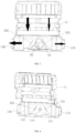
- the air conditioner body 1 includes a shell 11.
- the shell 11 is provided with a first air outlet 11A and a second air outlet 11B.
- a first end of the air supply pipeline 2 is connected to the first air outlet 11A.
- the first air supply port 4 is arranged at an inner front end of the cab, and the first air supply port 4 is connected to a second end of the first air supply pipeline 2.
- the first end of the second air supply pipeline 3 is connected to the second air outlet 11B.
- the second air supply port 6 is arranged at an inner rear end of the cab, and the second air supply port 6 is connected to a second end of the second air supply pipeline 3.
- the flow distribution device 5 includes a flow dividing portion 51 arranged in the shell 11.
- the flow dividing portion 51 is movably arranged relative to at least one of the first air outlet 11A or the second air outlet 11B so as to change an outlet air volume ratio of the air conditioner body 1.
- the outlet air volume ratio is a ratio of an air volume flowing out of the shell 11 from the first air outlet 11A to an air volume flowing out of the shell 11 from the second air outlet 11B.
- the relative position of the flow dividing portion 51 and at least one of the first air outlet 11A or the second air outlet 11B may be changed by moving the flow dividing portion 51 of the flow distribution device 5, so that the outlet air volume ratio of the air conditioner body 1 is changed, the change of the air supply ratio between the inner front end and the inner rear end of the cab is realized, and more air supply amount can be obtained in the direction which the driver faces.
- the air supplied by the air supply port behind the driver will not directly blow to the driver's body due to the blockage of the seat, and the driver's feeling on the air supply from the air conditioner mainly comes from the air supplied by the air supply port facing the driver; therefore, the air supply amount of the air supply port in front of the driver is more, and the comfortability of the driver is improved.
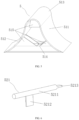
- the flow dividing portion 51 includes a first wind shielding surface 511, a second wind shielding surface 512 and a wind guide surface 513.
- the first wind shielding surface 511 is arranged between the first air outlet 11A and the second air outlet 11B.
- the second wind shielding surface 512 is arranged between the first wind shielding surface 511 and the second air outlet 11B.
- the wind guide surface 513 protrudes towards a wind coming side, and the wind guide surface 513 is in smooth connection with first wind shielding surface 511 and second wind shielding surface 512 respectively. This arrangement is beneficial to the distribution of the air volume between the first air outlet 11A and the second air outlet 11B, and is beneficial to the reduction of resistance and noise caused by the distribution.
- the first wind shielding surface 511 inclines towards the first air outlet 11A from the wind guide surface 513; and/or the second wind shielding surface 512 inclines towards the second air outlet 11B from the wind guide surface 513.
- This arrangement is beneficial for the airflow to flow stably between the first wind shielding surface 511 and the first air outlet 11A and/or between the second wind shielding surface 512 and the second air outlet 11B, and is beneficial to the reduction of resistance and noise caused by the change of the air volume distribution.
- one side of the first wind shielding surface 511 facing towards the first air outlet 11A is a recessed curved surface; and/or one side of the second wind shielding surface 512 facing towards the second air outlet 11B is a recessed curved surface.
- This arrangement is beneficial for the airflow to flow stably between the first wind shielding surface 511 and the first air outlet 11A and/or between the second wind shielding surface 512 and the second air outlet 11B, and is beneficial to the reduction of resistance and noise caused by the change of the air volume distribution.
- the first air outlet 11A and the second air outlet 11B are arranged oppositely and are respectively located on two opposite sides of the shell 11, and the flow dividing portion 51 is movably arranged between the first air outlet 11A and the second air outlet 11B.
- This arrangement may reduce the distance between the flow dividing portion 51 and one of the first air outlet 11A and the second air outlet 11B, and may increase the distance between the flow dividing portion 51 and the other one of the first air outlet 11A and the second air outlet 11B, thereby facilitating rapid adjustment of the outlet air volume ratio.
- the flow distribution device 5 further includes a driving portion.
- the driving portion 52 is in driving connection with the flow dividing portion 51, and is configured to change the relative position of the flow dividing portion 51 and at least one of the first air outlet 11A or the second air outlet 11B so as to change the outlet air volume ratio.
- the arrangement of the driving portion is beneficial to driving the flow dividing portion 51 to act to realize the required movement, thereby rapidly reaching the required outlet air volume ratio.
- the driving portion 52 includes a switching mechanism 521
- the flow dividing portion 51 includes a switching cooperation portion 514 cooperating with the switching mechanism 521
- the switching mechanism 521 is configured to move the switching cooperation portion 514 to drive the flow dividing portion 51 to move so as to change the relative position of the flow dividing portion 51 and at least one of the first air outlet 11A or the second air outlet 11B.
- the arrangement of the switching mechanism 521 facilitates the movement of the flow dividing portion 51, thereby rapidly adjusting the outlet air volume ratio.
- the switching mechanism 521 includes a rotating shaft 5211 and a switching plate 5212.
- the rotating shaft 5211 is rotatably arranged on the shell 11.
- the switching plate 5212 is connected to the rotating shaft 5211 and cooperates with the switching cooperation portion 514.
- the switching mechanism 521 includes the rotating shaft 5211 and the switching plate 5212 so as to facilitate the movement of the flow dividing portion 51 by rotating the rotating shaft 5211, thereby rapidly adjusting the outlet air volume ratio.
- the switching cooperation portion 514 includes an opening or groove formed in the flow dividing portion 51, and the switching mechanism 521 is inserted into the opening or groove.
- the switching cooperation portion 514 is arranged in the form of the opening or groove in the flow dividing portion 51.
- the switching cooperation portion 514 has a simple structure, is easy to process, and is beneficial to rapid assembling of the driving portion 52 and the flow dividing portion 51 and beneficial for the driving portion 52 to stably drive the flow dividing portion 51.
- the driving portion 52 includes an actuator, and the actuator is in driving connection with the flow dividing portion 51 to drive the flow dividing portion 51 to move so as to change the relative position of the flow dividing portion 51 and at least one of the first air outlet 11A or the second air outlet 11B.
- the driving portion 52 includes the actuator, which is beneficial to automatically adjusting the outlet air volume ratio and reducing the manual participation process.
- the actuator is not necessary, and the flow dividing portion may be driven to move by a manual driving mode instead of the actuator.
- the flow distribution device 5 further includes a limiting structure 53, and the limiting structure 53 is configured to limit the limit position of movement of the flow dividing portion 51.
- the arrangement of the limiting structure 53 is beneficial to avoiding over adjustment of the flow dividing portion 51 and to adjusting the outlet air volume ratio in a reasonable range.
- the limiting structure 53 includes at least one of a first limiting portion 531 or a second limiting portion 532.
- the first limiting portion 531 is configured to limit the limit position of the flow dividing portion 51 moving towards the first air outlet 11A.
- the second limiting portion 532 is configured to limit the limit position of the flow dividing portion 51 moving towards the second air outlet 11B.
- the limiting structure 53 is provided, and the limiting structure 53 includes at least one of the first limiting portion 531 or the second limiting portion 532, which are beneficial to avoiding over adjustment of the flow dividing portion 51 and to adjusting the outlet air volume ratio in a reasonable range.
- the limiting structure 53 includes a first protrusion arranged on an inner wall surface of the shell 11 and located between the flow dividing portion 51 and the first air outlet 11A, and/or a second protrusion arranged on an inner wall surface of the shell 11 and located between the flow dividing portion 51 and the second air outlet 11B.
- the limiting structure 53 is arranged in the form of the protrusion on the shell, and the limiting structure is simple and effective, and is beneficial to the stable adjustment range of the outlet air volume ratio.
- the first air supply pipeline 2 or the second air supply pipeline 3 includes an elbow pipe 21.
- the elbow pipe 21 includes an elbow pipe body 211 and at least one flow guide plate 212.
- the elbow pipe body 211 is provided with an inner flow channel.
- the flow guide plate 212 is located in the elbow pipe body 211. At least one flow guide plate 212 divides the inner flow channel of the elbow pipe body 211 into a plurality of flow passing areas.
- the flow guide plate 212 is arranged in the elbow pipe body 211, which is beneficial to uniform distribution of the air outlet volume of the plurality of air supply ports connected to the same air supply pipeline and is also beneficial to reducing large vortex flow at the elbow pipe 21, so that aerodynamic noise caused by the vortex flow is reduced.
- a surface of the flow guide plate 212 is provided with a plurality of flow guide grooves 2121 which extend along an extending direction of the elbow pipe body 211 and are arranged in parallel.
- the arrangement of the flow guide groove 2121 is beneficial to reducing large vortex flow at the elbow pipe 21, so that aerodynamic noise caused by the vortex flow is reduced.
- the forms of the plurality of flow guide grooves 2121 may be varied.
- the plurality of flow guide grooves 2121 are set as continuous triangular grooves.
- the plurality of flow guide grooves may also be spaced triangular grooves, continuous or spaced curved grooves, continuous or spaced square grooves, continuous or spaced trapezoidal grooves, continuous or spaced triangular or polygonal grooves with rounded transition, and the like.
- At least one first air supply port 4 or at least one second air supply port 6 includes an air supply body 41 and at least one barrier strip 43.
- the air supply body 41 is provided with an air supply channel arranged along an air supply direction.
- At least one barrier strip 43 is arranged in the air supply channel and has an included angle with the air supply direction.
- a first toothed structure 431 is arranged on a windward side of the barrier strip 43 facing towards the air supply direction and/or a second toothed structure 432 is arranged on a leeward side of the barrier strip 43 back to the air supply direction.
- the toothed structures of the first toothed structure 431 and the second toothed structure 432 may be the same or different.
- the forms of the first toothed structure 431 and the second toothed structure 432 may be varied.
- the first toothed structure 431 and the second toothed structure 432 in FIG. 9 to FIG. 12 may be set as continuous triangular teeth.
- the first toothed structure 431 or the second toothed structure 432 may be set as spaced triangular teeth, continuous or spaced curved teeth, continuous or spaced square teeth, continuous or spaced trapezoidal teeth, continuous or spaced triangular or polygonal teeth with rounded transition, and the like.
- At least two barrier strips 43 are arranged in parallel and at intervals on a plane perpendicular to the air supply direction; and/or at least two barrier strips 43 are crossed on a plane perpendicular to the air supply direction.
- the barrier strip 43 with the toothed structure is arranged in the air supply body 41 of the air supply port, and the plurality of barrier strips 43 are arranged reasonably, which are beneficial to reducing squealing noise prone to be generated at the corresponding air supply port in the cab.
- the engineering vehicle is a loader-digger.
- the engineering vehicle and the air conditioning system thereof provided by the embodiments of the present invention are further described by taking the loader-digger as an example and by combining with FIG. 1 to FIG. 12 .
- the air conditioning system mainly includes an air conditioner body 1, a first air supply pipeline 2, one or more first air supply ports 4, a second air supply pipeline 3, one or more second air supply ports 6 and a flow distribution device 5.
- the air conditioner body 1 includes a shell 11 and a refrigerant circulating system (not shown in the figures) arranged in the shell 11.
- the refrigerant circulating system mainly includes a compressor, a condenser, an expanding valve and an evaporator which are connected through a refrigerant pipeline.
- the shell 11 is provided with a first air outlet 11A and a second air outlet 11B.
- the first air outlet 11A and the second air outlet 11B are arranged oppositely and are respectively located on two opposite sides of the shell 11.
- the shell 11 is further provided with a first air inlet and a second air inlet.
- the first air inlet and the second air inlet are both located at the top of the shell 11.
- the air conditioner body 1 further includes a first air inlet port 12 communicating with the first air inlet, and a second air inlet port 13 communicating with the second air inlet.
- the first air inlet port 12 is used to supply fresh air introduced from the outside of the cab to the shell 11.
- the second air inlet port 13 is used to supply circulating air in the cab to the shell 11.
- a first end of the first air supply pipeline 2 is connected to the first air outlet 11A.
- the plurality of first air supply ports 4 are arranged at an inner front end of the cab, and each first air supply port 4 is connected to a second end of the first air supply pipeline 2.
- the shapes of the plurality of first air supply ports 4 may be the same or different.
- the plurality of first air supply ports 4 include a circular air supply port and a square air supply port.
- the air entering the air conditioner body 1 from the first air inlet and/or the second air inlet respectively flows out of the first air outlet 11A and the second air outlet 11B after being treated (such as refrigerated) by the refrigerant circulating system.
- the air flowing out of the first air outlet 11A is conveyed to each first air supply port 4 through the first air supply pipeline 2 and is conveyed into the cab from the front end of the cab.
- the first end of the second air supply pipeline 3 is connected to the second air outlet 11B.
- the plurality of second air supply ports 6 are arranged at an inner rear end of the cab, and each second air supply port 6 is connected to a second end of the second air supply pipeline 3.
- the shapes of the plurality of second air supply ports 6 may be the same or different.
- the plurality of second air supply ports 6 include a circular air supply port and a square air supply port.
- the air flowing out of the second air outlet 11B is conveyed to each second air supply port 6 through the second air supply pipeline 3 after being treated by the refrigerant circulating system, and is conveyed into the cab from the rear end of the cab.
- the first air supply port is arranged at the inner front end of the cab, and the second air supply port is arranged at the rear end of the cab, so there are air supply ports in front of and behind the seat.
- the air supplied from the air supply ports at the front end and the rear end blow to the front side and the back side of the driver's body.
- the working device of the loader-digger is at the digging end, the air supplied from the air supply ports at the front end and the rear end blow to the back side and the front side of the driver's body.
- the flow distribution device 5 includes a flow dividing portion 51 arranged in the shell 11, a driving portion 52 in driving connection with the flow dividing portion 51, and a limiting structure 53 for limiting the limit position of the movement of the flow dividing portion 51.
- the flow dividing portion 51 is movably arranged between the first air outlet 11A and the second air outlet 11B.
- the flow dividing portion 51 is movably arranged relative to the first air outlet 11A and the second air outlet 11B so as to change an outlet air volume ratio of the air conditioner body 1.
- the flow dividing portion 51 includes a curved plate protruding upward overally and a planar bottom plate located below the curved plate. Two ends of the curved plate are fixedly connected to two ends of the bottom plate. A hollow portion is formed between the curved plate and the bottom plate.
- a plurality of reinforcing plates 515 are arranged in the hollow portion, and the reinforcing plates 515 may be connected to a part of the curved plate with a larger curvature or may also be connected between the curved plate and the bottom plate.
- the flow dividing portion 51 includes a first wind shielding surface 511, a second wind shielding surface 512 and a wind guide surface 513 which are arranged on an outer surface of the curved plate.
- the first wind shielding surface 511 is arranged between the first air outlet 11A and the second air outlet 11B.
- the second wind shielding surface 512 is arranged between the first wind shielding surface 511 and the second air outlet 11B.
- the wind guide surface 513 protrudes towards the above (that is, the wind coming side).
- the wind guide surface 513 is in smooth connection with the first wind shielding surface 511 and the second wind shielding surface 512 respectively.
- the first wind shielding surface 511 inclines towards the first air outlet 11A from the wind guide surface 513, and the first wind shielding surface 511 facing towards the first air outlet 11A is a recessed curved surface.
- the second wind shielding surface 512 inclines towards the second air outlet 11B from the wind guide surface 513, and the second wind shielding surface 512 facing towards the second air outlet 11B is a recessed curved surface.
- the driving portion 52 is configured to change the relative position of the flow dividing portion 51 and the first air outlet 11A and the second air outlet 11B so as to change the outlet air volume ratio.
- the driving portion 52 includes a switching mechanism 521 and an actuator.
- the flow dividing portion 51 includes a switching cooperation portion 514 cooperating with the switching mechanism 521.
- the switching mechanism 521 is configured to move the switching cooperation portion 514 so as to drive the flow dividing portion 51 to move.
- the switching mechanism 521 includes a rotating shaft 5211 and a switching plate 5212.
- the rotating shaft 5211 is rotatably arranged on the shell 11.
- a sleeve 113 is arranged on an inner wall of the shell 11, and the rotating shaft 5211 extends into a center hole of the sleeve 113.
- the switching plate 5212 is connected below the rotating shaft 5211 and cooperates with the switching cooperation portion 514.
- the switching cooperation portion 514 includes an opening formed on the bottom plate of the flow dividing portion 51, and the opening is a rectangular hole.
- the switching mechanism 521 is arranged in the hollow portion of the flow dividing portion 51.
- the switching plate 5212 of the switching mechanism 521 is inserted into the rectangular hole.
- the actuator is in driving connection with the flow dividing portion 51 through the switching mechanism 521 so as to drive the flow dividing portion 51 to move.
- the actuator is a rotating motor which is in driving connection with the rotating shaft 5211.
- the rotating motor rotates to drive the rotating shaft 5211 to rotate, the rotating shaft 5211 rotates to drive the switching plate 5212 to swing, the switching plate 5212 swings to drive the flow dividing portion 51 to move towards the first air outlet 11A or move towards the second air outlet 11B, so that the flow passing area of a channel (arranged on the left sides in FIG. 2 and FIG.
- the limiting structure 53 includes a first limiting portion 531 and a second limiting portion 532.
- the first limiting portion 531 limits the limit position of the flow dividing portion 51 moving towards the first air outlet 11A.
- the second limiting portion 532 limits the limit position of the flow dividing portion 51 moving towards the second air outlet 11B.
- the first limiting portion 531 of the limiting structure 53 includes a first protrusion which is arranged on an inner wall surface of the shell 11 and is located between the flow dividing portion 51 and the first air outlet 11A.
- the second limiting portion 532 of the limiting structure 53 includes a second protrusion which is arranged on an inner wall surface of the shell 11 and is located between the flow dividing portion 51 and the second air outlet 11B.
- the first protrusion of the first limiting portion 531 is set as a strip-shaped protrusion which is consistent with the section shape of the first wind shielding surface 511.
- the second protrusion of the second limiting portion 532 is set as a strip-shaped protrusion which is consistent with the section shape of the second wind shielding surface 512. This arrangement is beneficial to improving the position certainty every time the flow dividing portion 51 arrives at the limit position, thereby contributing to the range stability of the outlet air volume ratio.
- a supporting base for placing the flow dividing portion 51 is arranged at the bottom of the inner wall of the shell 11.
- two supporting bases may be arranged between the first air outlet 11A and the second air outlet 11B at intervals, and the two supporting bases are respectively a first supporting base 111 and a second supporting base 112.
- the first air supply pipeline 2 includes an elbow pipe 21.
- the elbow pipe 21 includes an elbow pipe body 211 and two flow guide plates 212.
- the elbow pipe body 211 includes an inner flow channel.
- the flow guide plate 212 is located in the elbow pipe body 211.
- a surface of the flow guide plate 212 includes a plurality of flow guide grooves 2121 which extend along an extending direction of the elbow pipe body 211 and are arranged in parallel.
- the two flow guide plates 212 divide the inner flow channel of the elbow pipe body 211 into three flow passing areas.
- the section of the flow guide plate 212 perpendicular to the flowing direction of the elbow pipe body 211 includes a plurality of continuous triangular grooves. That is, the section shape of the flow guide groove 2121 is triangular, and the adjacent flow guide grooves 2121 are arranged without intervals.
- each first air supply port 4 and each second air supply port 6 include an air supply body 41 and at least one barrier strip 43.
- the following performs description by taking the circular first air supply port 4 shown in FIG. 9 and FIG. 10 and the square first air supply port 4 shown in FIG. 11 to FIG. 12 as an example.
- the structure of the second air supply port 6 may be referenced to the first air supply port 4.
- the first air supply port 4 includes an air supply body 41, an air volume adjusting plate 42 and a barrier strip 43.
- the air supply body 41 includes an air supply channel arranged along an air supply direction.
- the air volume adjusting plate 42 is arranged at the downstream of the barrier strip 43 along an air supply direction.
- the barrier strip 43 is arranged in the air supply channel and has an included angle with the air supply direction.
- a first toothed structure 431 is arranged on a windward side of the barrier strip 43 facing towards the air supply direction.
- a second toothed structure 432 is arranged on a leeward side of the barrier strip 43 back to the air supply direction.
- the first toothed structure 431 and the second toothed structure 432 are arranged uniformly along a length direction of the barrier strip 432.
- the first toothed structure 431 and the second toothed structure 432 on the section perpendicular to the length direction of the barrier strip 432 are provided with a plurality of continuous triangular teeth.
- two barrier strips 43 are perpendicularly crossed on a plane perpendicular to the air supply direction.
- two barrier strips 43 are arranged in parallel and at intervals on a plane perpendicular to the air supply direction.
- the actuator rotates the rotating shaft 5211 to drive the switching plate 5212 to swing, and the switching plate 5212 pushes the hole wall of the rectangular hole of the flow dividing portion 51 serving as the switching cooperation portion 514 while swinging, so that the flow dividing portion 51 moves under the supporting of the first supporting base 111 and the second supporting base 112, the flow passing area of the channel leading to the first air outlet 11A and the second air outlet 11B is changed, the air volume of the first air supply pipeline 2 supplied to the loading end and the air volume of the second air supply pipeline 3 supplied to the digging end are changed, the outlet air volume ratio is adjusted, the direction which the driver faces obtains more air volume, and the comfortability of the driver is improved.
- the first limiting portion 531 and the second limiting portion 532 of the limiting structure 53 determine the limit position of movement of the flow dividing portion 51.
- the flow dividing portion 51 and the switching mechanism 521 of the flow distribution device 5 are arranged at the position shown in FIG. 2 , and the second wind shielding surface 512 of the flow dividing portion 51 abuts to the second limiting structure 532.
- the channel leading to the first air outlet 11A for supplying air to the loading end is wider than the channel leading to the second air outlet 11B for supplying air to the digging end, the air volume supplied to the loading end is greater than the air volume supplied to the digging end, and the air volume blowing to the front side of the driver is greater than the air volume blowing to the back side of the driver.
- the direction of the arrow in FIG. 2 represents the air supply direction, and the thickness of the arrow represents the air volume.
- the flow dividing portion 51 and the switching mechanism 521 of the flow distribution device 5 are arranged at the position shown in FIG. 3 , and the first wind shielding surface 511 of the flow dividing portion 51 abuts to the first limiting structure 531.
- the channel leading to the first air outlet 11A for supplying air to the loading end is narrower than the channel leading to the second air outlet 11B for supplying air to the digging end, the air volume supplied to the digging end is greater than the air volume supplied to the loading end, and the air volume blowing to the front side of the driver is greater than the air volume blowing to the back side of the driver.
- the direction of the arrow in FIG. 3 represents the air supply direction, and the thickness of the arrow represents the air volume.
- a flow guide plate 212 extending along the flowing direction of the inner flow channel is arranged at the inner flow channel of the elbow pipe body 211 of the elbow pipe 21 in the second air supply pipeline 3, the radian of the flow guide plate 212 is consistent with the radian of the elbow pipe body 211, the flow velocity of the air in the inner flow channel of the elbow pipe body 211 is uniform, and it is beneficial to reduce the air volume difference between the radial inner side and outer side of the elbow pipe body 211, thereby facilitating uniform distribution of the air volume of each air supply port supplied air to the same end of the cab.
- the arrangement of the flow guide plate 212 is beneficial to reducing the vortex flow and reducing the noise of the vortex flow.
- a plurality of flow guide grooves 2121 are arranged on two sides of the flow guide plate 212, which can comb the vortex flow at the elbow pipe 21 and is beneficial to reducing the noise of the vortex flow.
- the barrier strip 43 forming an included angle with the air supply direction is arranged in the air supply channel of the air supply port, and the barrier strip 43 includes the toothed structure. Further, in order to match with the shape of the air supply body 41 of the air supply port, the barrier strips 43 of the circular air supply ports are designed into crossed arrangement, and the barrier strips 43 of the rectangular air supply ports are arranged into parallel arrangement.
- the toothed structure on the barrier strip 43 acts as a vortex generator during air supply, the large-scale vortex is converted into several small vortex flow, and the contribution of the discrete vortex to the space-induced velocity field is much smaller than that of single concentrated vortex flow, so that the toothed structure can play a role in silencing and reducing noise, and it is beneficial to reduce the squealing noise at the air supply port.
Landscapes
- Engineering & Computer Science (AREA)
- Physics & Mathematics (AREA)
- Thermal Sciences (AREA)
- Mechanical Engineering (AREA)
- Mining & Mineral Resources (AREA)
- Civil Engineering (AREA)
- General Engineering & Computer Science (AREA)
- Structural Engineering (AREA)
- Air-Conditioning For Vehicles (AREA)
Applications Claiming Priority (2)
| Application Number | Priority Date | Filing Date | Title |
|---|---|---|---|
| CN202111156890.1A CN113858912A (zh) | 2021-09-30 | 2021-09-30 | 工程车辆及其空调系统 |
| PCT/CN2021/129636 WO2022160858A1 (zh) | 2021-09-30 | 2021-11-09 | 工程车辆及其空调系统 |
Publications (3)
| Publication Number | Publication Date |
|---|---|
| EP4112340A1 EP4112340A1 (en) | 2023-01-04 |
| EP4112340A4 EP4112340A4 (en) | 2024-04-24 |
| EP4112340B1 true EP4112340B1 (en) | 2025-06-25 |
Family
ID=79001015
Family Applications (1)
| Application Number | Title | Priority Date | Filing Date |
|---|---|---|---|
| EP21922448.2A Active EP4112340B1 (en) | 2021-09-30 | 2021-11-09 | Engineering vehicle and air-conditioning system thereof |
Country Status (5)
| Country | Link |
|---|---|
| US (1) | US12545078B2 (pl) |
| EP (1) | EP4112340B1 (pl) |
| CN (1) | CN113858912A (pl) |
| PL (1) | PL4112340T3 (pl) |
| WO (1) | WO2022160858A1 (pl) |
Families Citing this family (3)
| Publication number | Priority date | Publication date | Assignee | Title |
|---|---|---|---|---|
| CN114750659B (zh) * | 2022-04-12 | 2023-09-15 | 延锋国际座椅系统有限公司 | 一种多向通风调节系统及座椅 |
| CN116101388A (zh) * | 2023-01-06 | 2023-05-12 | 江苏徐工工程机械研究院有限公司 | 一种拖拉机驾驶室顶棚及拖拉机 |
| JP2024149210A (ja) * | 2023-04-07 | 2024-10-18 | 株式会社デンソー | 音低減装置 |
Family Cites Families (17)
| Publication number | Priority date | Publication date | Assignee | Title |
|---|---|---|---|---|
| FR2761305B1 (fr) * | 1997-03-25 | 1999-06-18 | Valeo Climatisation | Dispositif de chauffage-ventilation pour vehicule automobile a commande selective selon les zones de l'habitacle |
| CN101358779A (zh) * | 2008-09-25 | 2009-02-04 | 上海交通大学 | 一种车用二氧化碳空调系统 |
| US8087491B2 (en) * | 2010-01-08 | 2012-01-03 | General Electric Company | Vane type silencers in elbow for gas turbine |
| US8610382B2 (en) * | 2010-12-23 | 2013-12-17 | Caterpillar Inc. | Active high voltage bus bleed down |
| CN202727922U (zh) | 2012-08-05 | 2013-02-13 | 江苏创导空调有限公司 | 侧出风式小型挖掘机空调 |
| CN203876535U (zh) * | 2014-04-30 | 2014-10-15 | 洛阳北方易初摩托车有限公司 | 一种车载空调的蒸发器箱体总成的出风、回风系统 |
| CN203958155U (zh) * | 2014-06-28 | 2014-11-26 | 南车青岛四方机车车辆股份有限公司 | 轨道车辆调节风量装置 |
| CN106196544B (zh) * | 2015-05-08 | 2020-06-26 | 杭州三花研究院有限公司 | 汽车空调系统的进风装置及汽车空调系统 |
| CN106541801B (zh) | 2016-01-07 | 2020-03-17 | 徐工集团工程机械股份有限公司 | 空调风道、空调系统及清扫车 |
| CN106274942B (zh) * | 2016-08-29 | 2018-08-07 | 金鑫美莱克空调系统(无锡)有限公司 | 轨道交通空调用可调节分配风道及其控制方法 |
| CN206031382U (zh) * | 2016-08-29 | 2017-03-22 | 金鑫美莱克空调系统(无锡)有限公司 | 轨道交通空调用可调节分配风道 |
| CN106274379A (zh) * | 2016-08-31 | 2017-01-04 | 徐工集团工程机械有限公司 | 出风装置、空调和工程机械 |
| CN206781485U (zh) * | 2017-05-09 | 2017-12-22 | 广西柳工机械股份有限公司 | 工程机械驾驶室空调送风系统 |
| DE102019200381A1 (de) * | 2019-01-15 | 2020-07-16 | Siemens Mobility GmbH | Klimatisierungsanordnung für ein Schienenfahrzeug |
| CN210062982U (zh) * | 2019-04-29 | 2020-02-14 | 中车青岛四方机车车辆股份有限公司 | 车辆送回风结构及具有该结构的轨道车辆 |
| CN112440679B (zh) * | 2019-08-31 | 2023-01-06 | 比亚迪股份有限公司 | 车辆的空调出风结构、车辆空调系统及车辆 |
| CN211969111U (zh) * | 2019-12-31 | 2020-11-20 | 北京车和家信息技术有限公司 | 风道组件、空调、出风装置和汽车 |
-
2021
- 2021-09-30 CN CN202111156890.1A patent/CN113858912A/zh active Pending
- 2021-11-09 PL PL21922448.2T patent/PL4112340T3/pl unknown
- 2021-11-09 US US17/916,950 patent/US12545078B2/en active Active
- 2021-11-09 WO PCT/CN2021/129636 patent/WO2022160858A1/zh not_active Ceased
- 2021-11-09 EP EP21922448.2A patent/EP4112340B1/en active Active
Also Published As
| Publication number | Publication date |
|---|---|
| CN113858912A (zh) | 2021-12-31 |
| EP4112340A4 (en) | 2024-04-24 |
| US12545078B2 (en) | 2026-02-10 |
| WO2022160858A1 (zh) | 2022-08-04 |
| PL4112340T3 (pl) | 2025-10-27 |
| US20230150338A1 (en) | 2023-05-18 |
| EP4112340A1 (en) | 2023-01-04 |
Similar Documents
| Publication | Publication Date | Title |
|---|---|---|
| EP4112340B1 (en) | Engineering vehicle and air-conditioning system thereof | |
| US6814137B2 (en) | Automotive air conditioner | |
| US10017031B2 (en) | Heat exchanger arrangement for heat uptake and air conditioning system of a motor vehicle | |
| US20060116064A1 (en) | Ceiling air-blowing device for a vehicle air conditioner | |
| CN100475584C (zh) | 用于汽车内部空调装置的部件和汽车内部空调装置 | |
| EP3078917B1 (en) | Ceiling-mounted air-conditioner indoor-unit system | |
| JPH0317461A (ja) | 自動車の空調風吹出装置 | |
| WO2015146124A1 (ja) | 空気吹出装置 | |
| CN109353188B (zh) | 基于可调导流板的方舱均匀送风道 | |
| CN212511431U (zh) | 空调室内机及空调器 | |
| CN112440676B (zh) | 车辆的空调出风口结构、空调系统和车辆 | |
| US10350962B2 (en) | Assembly for air distribution for an air conditioning system of an automobile | |
| US20070144727A1 (en) | Air conditioner for vehicle | |
| GB2355787A (en) | Ventilation of Central Console for Vehicles | |
| US7575511B2 (en) | Temperature door for a vehicle and heating, ventilation, and air conditioning system | |
| US10507712B2 (en) | HVAC door with dentil features | |
| US20080245501A1 (en) | Console Air Conditioner for Vehicle | |
| US20070137832A1 (en) | Component for a device for air-conditioning the inside of a vehicle and device for air-conditioning the inside of a vehicle | |
| CN212447548U (zh) | 单台空调机组的城轨车辆空调及通风系统 | |
| EP4129718B1 (en) | Air outlet structure, column, and vehicle | |
| CN114060924A (zh) | 空调室内机及空调器 | |
| US11945285B2 (en) | Air discharge device | |
| CN111365766B (zh) | 空调室内机及空调器 | |
| KR20140004090A (ko) | 공기 조화기 | |
| CN221315731U (zh) | 一种车载风道系统和车辆 |
Legal Events
| Date | Code | Title | Description |
|---|---|---|---|
| STAA | Information on the status of an ep patent application or granted ep patent |
Free format text: STATUS: THE INTERNATIONAL PUBLICATION HAS BEEN MADE |
|
| PUAI | Public reference made under article 153(3) epc to a published international application that has entered the european phase |
Free format text: ORIGINAL CODE: 0009012 |
|
| STAA | Information on the status of an ep patent application or granted ep patent |
Free format text: STATUS: REQUEST FOR EXAMINATION WAS MADE |
|
| 17P | Request for examination filed |
Effective date: 20220926 |
|
| AK | Designated contracting states |
Kind code of ref document: A1 Designated state(s): AL AT BE BG CH CY CZ DE DK EE ES FI FR GB GR HR HU IE IS IT LI LT LU LV MC MK MT NL NO PL PT RO RS SE SI SK SM TR |
|
| A4 | Supplementary search report drawn up and despatched |
Effective date: 20240325 |
|
| RIC1 | Information provided on ipc code assigned before grant |
Ipc: B60H 1/00 20060101AFI20240319BHEP |
|
| DAV | Request for validation of the european patent (deleted) | ||
| DAX | Request for extension of the european patent (deleted) | ||
| GRAP | Despatch of communication of intention to grant a patent |
Free format text: ORIGINAL CODE: EPIDOSNIGR1 |
|
| STAA | Information on the status of an ep patent application or granted ep patent |
Free format text: STATUS: GRANT OF PATENT IS INTENDED |
|
| RIC1 | Information provided on ipc code assigned before grant |
Ipc: E02F 9/16 20060101ALI20250313BHEP Ipc: B60H 1/00 20060101AFI20250313BHEP |
|
| INTG | Intention to grant announced |
Effective date: 20250328 |
|
| GRAS | Grant fee paid |
Free format text: ORIGINAL CODE: EPIDOSNIGR3 |
|
| GRAA | (expected) grant |
Free format text: ORIGINAL CODE: 0009210 |
|
| STAA | Information on the status of an ep patent application or granted ep patent |
Free format text: STATUS: THE PATENT HAS BEEN GRANTED |
|
| P01 | Opt-out of the competence of the unified patent court (upc) registered |
Free format text: CASE NUMBER: APP_19424/2025 Effective date: 20250423 |
|
| AK | Designated contracting states |
Kind code of ref document: B1 Designated state(s): AL AT BE BG CH CY CZ DE DK EE ES FI FR GB GR HR HU IE IS IT LI LT LU LV MC MK MT NL NO PL PT RO RS SE SI SK SM TR |
|
| REG | Reference to a national code |
Ref country code: GB Ref legal event code: FG4D |
|
| REG | Reference to a national code |
Ref country code: CH Ref legal event code: EP |
|
| REG | Reference to a national code |
Ref country code: CH Ref legal event code: EP |
|
| REG | Reference to a national code |
Ref country code: IE Ref legal event code: FG4D |
|
| REG | Reference to a national code |
Ref country code: DE Ref legal event code: R096 Ref document number: 602021033111 Country of ref document: DE |
|
| PG25 | Lapsed in a contracting state [announced via postgrant information from national office to epo] |
Ref country code: FI Free format text: LAPSE BECAUSE OF FAILURE TO SUBMIT A TRANSLATION OF THE DESCRIPTION OR TO PAY THE FEE WITHIN THE PRESCRIBED TIME-LIMIT Effective date: 20250625 |
|
| REG | Reference to a national code |
Ref country code: LT Ref legal event code: MG9D |
|
| PG25 | Lapsed in a contracting state [announced via postgrant information from national office to epo] |
Ref country code: NO Free format text: LAPSE BECAUSE OF FAILURE TO SUBMIT A TRANSLATION OF THE DESCRIPTION OR TO PAY THE FEE WITHIN THE PRESCRIBED TIME-LIMIT Effective date: 20250925 Ref country code: GR Free format text: LAPSE BECAUSE OF FAILURE TO SUBMIT A TRANSLATION OF THE DESCRIPTION OR TO PAY THE FEE WITHIN THE PRESCRIBED TIME-LIMIT Effective date: 20250926 |
|
| PG25 | Lapsed in a contracting state [announced via postgrant information from national office to epo] |
Ref country code: BG Free format text: LAPSE BECAUSE OF FAILURE TO SUBMIT A TRANSLATION OF THE DESCRIPTION OR TO PAY THE FEE WITHIN THE PRESCRIBED TIME-LIMIT Effective date: 20250625 |
|
| PG25 | Lapsed in a contracting state [announced via postgrant information from national office to epo] |
Ref country code: HR Free format text: LAPSE BECAUSE OF FAILURE TO SUBMIT A TRANSLATION OF THE DESCRIPTION OR TO PAY THE FEE WITHIN THE PRESCRIBED TIME-LIMIT Effective date: 20250625 |
|
| PG25 | Lapsed in a contracting state [announced via postgrant information from national office to epo] |
Ref country code: RS Free format text: LAPSE BECAUSE OF FAILURE TO SUBMIT A TRANSLATION OF THE DESCRIPTION OR TO PAY THE FEE WITHIN THE PRESCRIBED TIME-LIMIT Effective date: 20250925 |
|
| PG25 | Lapsed in a contracting state [announced via postgrant information from national office to epo] |
Ref country code: LV Free format text: LAPSE BECAUSE OF FAILURE TO SUBMIT A TRANSLATION OF THE DESCRIPTION OR TO PAY THE FEE WITHIN THE PRESCRIBED TIME-LIMIT Effective date: 20250625 |
|
| REG | Reference to a national code |
Ref country code: NL Ref legal event code: MP Effective date: 20250625 |
|
| PG25 | Lapsed in a contracting state [announced via postgrant information from national office to epo] |
Ref country code: NL Free format text: LAPSE BECAUSE OF FAILURE TO SUBMIT A TRANSLATION OF THE DESCRIPTION OR TO PAY THE FEE WITHIN THE PRESCRIBED TIME-LIMIT Effective date: 20250625 |
|
| PG25 | Lapsed in a contracting state [announced via postgrant information from national office to epo] |
Ref country code: PT Free format text: LAPSE BECAUSE OF FAILURE TO SUBMIT A TRANSLATION OF THE DESCRIPTION OR TO PAY THE FEE WITHIN THE PRESCRIBED TIME-LIMIT Effective date: 20251027 |
|
| REG | Reference to a national code |
Ref country code: AT Ref legal event code: MK05 Ref document number: 1806138 Country of ref document: AT Kind code of ref document: T Effective date: 20250625 |
|
| PG25 | Lapsed in a contracting state [announced via postgrant information from national office to epo] |
Ref country code: IS Free format text: LAPSE BECAUSE OF FAILURE TO SUBMIT A TRANSLATION OF THE DESCRIPTION OR TO PAY THE FEE WITHIN THE PRESCRIBED TIME-LIMIT Effective date: 20251025 |
|
| PGFP | Annual fee paid to national office [announced via postgrant information from national office to epo] |
Ref country code: GB Payment date: 20251030 Year of fee payment: 5 |
|
| PG25 | Lapsed in a contracting state [announced via postgrant information from national office to epo] |
Ref country code: AT Free format text: LAPSE BECAUSE OF FAILURE TO SUBMIT A TRANSLATION OF THE DESCRIPTION OR TO PAY THE FEE WITHIN THE PRESCRIBED TIME-LIMIT Effective date: 20250625 Ref country code: SM Free format text: LAPSE BECAUSE OF FAILURE TO SUBMIT A TRANSLATION OF THE DESCRIPTION OR TO PAY THE FEE WITHIN THE PRESCRIBED TIME-LIMIT Effective date: 20250625 |
|
| PGFP | Annual fee paid to national office [announced via postgrant information from national office to epo] |
Ref country code: TR Payment date: 20251106 Year of fee payment: 5 |
|
| PG25 | Lapsed in a contracting state [announced via postgrant information from national office to epo] |
Ref country code: CZ Free format text: LAPSE BECAUSE OF FAILURE TO SUBMIT A TRANSLATION OF THE DESCRIPTION OR TO PAY THE FEE WITHIN THE PRESCRIBED TIME-LIMIT Effective date: 20250625 |
|
| PGFP | Annual fee paid to national office [announced via postgrant information from national office to epo] |
Ref country code: PL Payment date: 20251027 Year of fee payment: 5 |
|
| PG25 | Lapsed in a contracting state [announced via postgrant information from national office to epo] |
Ref country code: EE Free format text: LAPSE BECAUSE OF FAILURE TO SUBMIT A TRANSLATION OF THE DESCRIPTION OR TO PAY THE FEE WITHIN THE PRESCRIBED TIME-LIMIT Effective date: 20250625 |
|
| PG25 | Lapsed in a contracting state [announced via postgrant information from national office to epo] |
Ref country code: SK Free format text: LAPSE BECAUSE OF FAILURE TO SUBMIT A TRANSLATION OF THE DESCRIPTION OR TO PAY THE FEE WITHIN THE PRESCRIBED TIME-LIMIT Effective date: 20250625 |
|
| PG25 | Lapsed in a contracting state [announced via postgrant information from national office to epo] |
Ref country code: ES Free format text: LAPSE BECAUSE OF FAILURE TO SUBMIT A TRANSLATION OF THE DESCRIPTION OR TO PAY THE FEE WITHIN THE PRESCRIBED TIME-LIMIT Effective date: 20250625 |
|
| PG25 | Lapsed in a contracting state [announced via postgrant information from national office to epo] |
Ref country code: RO Free format text: LAPSE BECAUSE OF FAILURE TO SUBMIT A TRANSLATION OF THE DESCRIPTION OR TO PAY THE FEE WITHIN THE PRESCRIBED TIME-LIMIT Effective date: 20250625 |
|
| PG25 | Lapsed in a contracting state [announced via postgrant information from national office to epo] |
Ref country code: DK Free format text: LAPSE BECAUSE OF FAILURE TO SUBMIT A TRANSLATION OF THE DESCRIPTION OR TO PAY THE FEE WITHIN THE PRESCRIBED TIME-LIMIT Effective date: 20250625 |
|
| PG25 | Lapsed in a contracting state [announced via postgrant information from national office to epo] |
Ref country code: IT Free format text: LAPSE BECAUSE OF FAILURE TO SUBMIT A TRANSLATION OF THE DESCRIPTION OR TO PAY THE FEE WITHIN THE PRESCRIBED TIME-LIMIT Effective date: 20250625 |