EP4112877A2 - Screen handling system - Google Patents
Screen handling system Download PDFInfo
- Publication number
- EP4112877A2 EP4112877A2 EP22182164.8A EP22182164A EP4112877A2 EP 4112877 A2 EP4112877 A2 EP 4112877A2 EP 22182164 A EP22182164 A EP 22182164A EP 4112877 A2 EP4112877 A2 EP 4112877A2
- Authority
- EP
- European Patent Office
- Prior art keywords
- screen
- axis
- pad
- gripper
- handling system
- Prior art date
- Legal status (The legal status is an assumption and is not a legal conclusion. Google has not performed a legal analysis and makes no representation as to the accuracy of the status listed.)
- Granted
Links
Images




Classifications
-
- E—FIXED CONSTRUCTIONS
- E21—EARTH OR ROCK DRILLING; MINING
- E21D—SHAFTS; TUNNELS; GALLERIES; LARGE UNDERGROUND CHAMBERS
- E21D20/00—Setting anchoring-bolts
- E21D20/003—Machines for drilling anchor holes and setting anchor bolts
-
- E—FIXED CONSTRUCTIONS
- E21—EARTH OR ROCK DRILLING; MINING
- E21D—SHAFTS; TUNNELS; GALLERIES; LARGE UNDERGROUND CHAMBERS
- E21D11/00—Lining tunnels, galleries or other underground cavities, e.g. large underground chambers; Linings therefor; Making such linings in situ, e.g. by assembling
- E21D11/14—Lining predominantly with metal
- E21D11/15—Plate linings; Laggings, i.e. linings designed for holding back formation material or for transmitting the load to main supporting members
- E21D11/152—Laggings made of grids or nettings
-
- E—FIXED CONSTRUCTIONS
- E21—EARTH OR ROCK DRILLING; MINING
- E21D—SHAFTS; TUNNELS; GALLERIES; LARGE UNDERGROUND CHAMBERS
- E21D21/00—Anchoring-bolts for roof, floor in galleries or longwall working, or shaft-lining protection
- E21D21/0093—Accessories
-
- E—FIXED CONSTRUCTIONS
- E21—EARTH OR ROCK DRILLING; MINING
- E21D—SHAFTS; TUNNELS; GALLERIES; LARGE UNDERGROUND CHAMBERS
- E21D11/00—Lining tunnels, galleries or other underground cavities, e.g. large underground chambers; Linings therefor; Making such linings in situ, e.g. by assembling
- E21D11/40—Devices or apparatus specially adapted for handling or placing units of linings or supporting units for tunnels or galleries
Definitions
- the present disclosure relates to rock drilling and bolting devices.
- a support member e.g., a wire screen
- a support member may be secured adjacent a rock face by one or more bolts.
- the installation of a rock bolt includes drilling a hole in a rock face and inserting a bolt through the support member and into the drilled hole, thereby securing the support member against the rock face.
- a screen handling system for a rock drilling device.
- the rock drilling device includes a feed assembly, at least one rail system supporting the feed assembly for translational movement relative to the boom along a first axis, and an actuator for advancing a bit or bolt into a rock face parallel to the first axis.
- the screen handling system includes a pad disposed proximate the bit or bolt, a block having a bore that defines a second axis parallel to the first axis, and a gripper at least partially disposed within and axially moveable relative to the bore in a direction along the second axis.
- the screen handling system further includes a drive mechanism coupled to the block that is capable of continuously rotating the pad about the second axis to a desired orientation.
- a method of installing a screen on a rock face includes grasping the screen with a stinger assembly by securing a portion of the screen between a pad and a gripper, actuating a feed assembly that supports the stinger assembly to extend toward the rock face until the screen is adjacent the rock face, continuously rotating the pad and the screen via a slew drive mechanism to precisely position the screen in a desired orientation relative to the mine face, and engaging the gripper against the rock face to stabilize the feed assembly relative to the rock face.
- the method further includes driving a bit or bolt through the screen and into the rock face to hold the screen against the rock face.
- connection and “coupled” are not restricted to physical or mechanical connections or couplings, whether direct or indirect. Terms of degree, such as “substantially,” “about,” “approximately,” etc. are understood by those of ordinary skill to refer to reasonable ranges outside of the given value, for example, general tolerances associated with manufacturing, assembly, and use of the described embodiments.
- FIG. 1 illustrates a feed assembly 10 supported on a boom 14 of a mining machine.
- the feed assembly 10 includes a mounting frame 18 that is pivotably coupled to the boom 14 and moveable relative thereto via one or more boom actuators 22 (e.g., hydraulic cylinders, rotary motors, etc.).
- boom actuators 22 e.g., hydraulic cylinders, rotary motors, etc.
- the mining machine is positioned within a mine and the boom 14 supports the feed assembly 10 to be positioned in a desired orientation adjacent a rock face 26.
- the screen handling system includes a stinger assembly 34 that is capable of engaging and maneuvering a support member (e.g., a screen 30 - FIG. 3 ) against the rock face 26.
- the stinger assembly 34 includes a stinger pad 38 having an aperture 42, a finger gripper 46 that may engage (e.g., hook around a portion of) the mesh screen ( FIG. 3 ), and a stinger block 50 that supports the finger gripper cylinder 46 for movement.
- the finger gripper 46 is moveable along a stinger axis 54 between a retracted position ( FIG.
- the gripper 46 is part of an actuator subassembly 48.
- the gripper 46 is driven hydraulically between the retracted and the extended position.
- the gripper 46 includes a main body 62 that is at least partially supported within a bore 64 ( FIG. 2 ) of the stinger block 50, a head 66, and a neck 70 positioned between the main body 62 and the head 66.
- the head 66 has a convex or conical profile to facilitate movement of the head 66 through a wire segment of the screen 30 and subsequent gripping of the screen 30 via the head 66.
- the neck 70 has a reduced-diameter relative to the head 66, thereby allowing a portion of the head 66 (e.g., an outer periphery of the head 66) to engage and hold the mesh screen 30.
- the portion of the head 66 includes a shoulder 72 having a plurality of hooks 74 that extend rearwardly from the head 66 in a direction parallel to the stinger axis 54. Each hook 74 is configured to hook around a portion of the screen 30.
- the finger gripper 46 is moved to the extended position, enabling the head 66 to extend through and engage the screen 30.
- the finger gripper 46 may then be retracted along the stinger axis 54 until the portion of the screen 30 is secured between the head 66 of the finger gripper 46 and the front face 58 of the stinger pad 38.
- the head 66 protrudes beyond the front face 58 of the stringer pad 38 while the screen 30 is secured due to a mechanical interference with the screen 30 lodged in the neck 70.
- the screen 30 may be maneuvered into a desired position and orientation relative to the rock face 26.
- the stinger assembly 34 further includes a drive mechanism (e.g., hydraulic slew drive 78).
- the hydraulic slew drive mechanism 78 is supported by the stinger block 50 (as shown in FIG. 2 ) and includes a housing 82, a worm wheel 86 disposed within the housing 82, and a threaded shaft or worm gear 90 that engages and drives the worm wheel 86 for rotation about the stinger axis 54.
- the worm gear 90 includes helical teeth 92 that engage corresponding helical teeth 94 of the worm wheel 86.
- a gear ratio between the worm gear 90 and the worm wheel 86 determines a rotational output of a hydraulic motor 98 to the worm wheel 86.
- the worm gear 90 is driven by the hydraulic motor 98 about a motor axis 102 that is perpendicular to the stinger axis 54.
- the stinger pad 38 is coupled to the worm wheel 82 (e.g., via bolts 89) for co-rotation therewith.
- the slew drive mechanism 78 permits the worm wheel 82 (and therefore the stinger pad 38) to be continuously and completely rotated about the stinger axis 54 and may be rotated to any number of positions or orientations. Stated another way, the worm gear 86 can drive the worm wheel 82 (and therefore the stinger pad 38) through virtually infinite rotations. Since the screen 30 is forcibly held against the stinger pad 38 by the finger gripper 46, the screen 30 rotates with the stinger pad 38 and can be precisely oriented and/or positioned relative to the rock face 26.
- the stinger pad 38 When the hydraulic motor 98 is deactivated, the stinger pad 38 immediately stops rotating due to a fixed gear ratio between the worm wheel 86 and the worm gear 90 even though the screen may exert a reaction torque (e.g., due to rotational inertia) on the stinger pad 38 when stopped abruptly.
- the slew drive mechanism 78 provides a compact drive mechanism that permits the stinger assembly to have a shorter length than conventional screen handling devices. The compact length reduces the amount of weight that is supported in a cantilevered manner by the boom 14, thereby also reducing the counterweight needed to maintain balance for the feed assembly 10.
- the stinger assembly 34 is supported on the feed assembly 10 that is capable of extending and retracting the stinger assembly 34 along the stinger axis 54 relative to the mounting frame 18.
- a first rail system 110 couples the feed assembly 10 for translation relative to the mounting frame 18.
- a feed actuator e.g. a hydraulic cylinder 114 is coupled between the mounting frame 18 and the feed assembly 10, and is actuatable to move the feed assembly 10 along the first rail system 110 between a first position ( FIG. 7 ) and a second position ( FIG. 8 ). In the first position, the stinger assembly 34 may be spaced away from the rock face 26 ( FIG. 1 ).
- the feed actuator 114 can actuate the feed assembly 10 toward the second position at which the stinger assembly 34 is positioned adjacent the rock face 26. Placing the stinger assembly 34 against the mine face 26 (sometimes referred to as “stinging the face"), the feed assembly 10 is held stable against the rock face 26 to inhibit the screen handling system from moving relative to the rock face 26 during a drilling and bolting operation.
- the feed assembly 10 further includes a drill feed 118, consumable 122 (e.g., a drill bit, resin cartridge, bolt, etc.), and a second rail system 126 that supports the drill feed 118 for translational movement along drill axis 130.
- the drill feed 118 rotationally drives (e.g., via a motor) and advances a drill bit 122 into the rock face 26 as the drill feed 118 translates along the second rail system 126.
- a hydraulic actuator, belt drive, or some other linear actuator moves the drill feed 118 along the second rail system 126.
- the feed assembly 10 further includes a cable handler 134 that facilitates gathering and guiding drill feed cables (not shown) as the drill feed 118 translates.
- a cable handler 134 that facilitates gathering and guiding drill feed cables (not shown) as the drill feed 118 translates.
- the bolting assembly 1106 may include a stinger assembly 34 with the hydraulic slew drive mechanism 78, the drill feed 118, and the rock drill 122. Furthermore, the bolting assembly 1106 may include a carousel 1136 for holding various tools used during the drilling and bolting operation.
Landscapes
- Engineering & Computer Science (AREA)
- Mining & Mineral Resources (AREA)
- Structural Engineering (AREA)
- Life Sciences & Earth Sciences (AREA)
- General Life Sciences & Earth Sciences (AREA)
- Geochemistry & Mineralogy (AREA)
- Geology (AREA)
- Architecture (AREA)
- Civil Engineering (AREA)
- Earth Drilling (AREA)
- Load-Engaging Elements For Cranes (AREA)
- Manufacture And Refinement Of Metals (AREA)
Abstract
Description
- This application claims priority to co-pending, prior-filed
U.S. Provisional Patent Application No. 63/216,967, filed on June 30, 2021 - The present disclosure relates to rock drilling and bolting devices.
- In order to prevent rock falls in a mine, a support member (e.g., a wire screen) may be secured adjacent a rock face by one or more bolts. In some applications, the installation of a rock bolt includes drilling a hole in a rock face and inserting a bolt through the support member and into the drilled hole, thereby securing the support member against the rock face.
- In one independent aspect, a screen handling system is provided for a rock drilling device. The rock drilling device includes a feed assembly, at least one rail system supporting the feed assembly for translational movement relative to the boom along a first axis, and an actuator for advancing a bit or bolt into a rock face parallel to the first axis. The screen handling system includes a pad disposed proximate the bit or bolt, a block having a bore that defines a second axis parallel to the first axis, and a gripper at least partially disposed within and axially moveable relative to the bore in a direction along the second axis. The screen handling system further includes a drive mechanism coupled to the block that is capable of continuously rotating the pad about the second axis to a desired orientation.
- In another independent aspect, a rock drilling device for use on a boom of a mining machine includes a feed assembly; a first frame at least partially supported by the feed assembly for translational movement relative to the boom along a first axis and a second frame supported for translational movement relative to the first frame; a drill feed coupled to the second frame for rotating and advancing a bit or bolt into a rock face along a second axis that is parallel to the first axis; and a screen handler coupled to the first rail system and configured to connect to and maneuver a screen relative to the rock face by rotating the screen through an infinite number of rotations.
- In yet another independent aspect, a method of installing a screen on a rock face includes grasping the screen with a stinger assembly by securing a portion of the screen between a pad and a gripper, actuating a feed assembly that supports the stinger assembly to extend toward the rock face until the screen is adjacent the rock face, continuously rotating the pad and the screen via a slew drive mechanism to precisely position the screen in a desired orientation relative to the mine face, and engaging the gripper against the rock face to stabilize the feed assembly relative to the rock face. The method further includes driving a bit or bolt through the screen and into the rock face to hold the screen against the rock face.
- Other aspects will become apparent by consideration of the detailed description and accompanying drawings.
-
-
FIG. 1 is a side view of a screen handling system of a feed assembly supported on a boom. -
FIG. 2 is an exploded perspective view of a stinger assembly. -
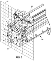
FIG. 3 is a perspective view of the stinger assembly ofFIG. 2 , illustrating a gripper engaging a screen. -
FIG. 4 is a perspective view of the stinger assembly ofFIG. 2 , illustrating a gripper in a retracted position. -
FIG. 5 is a cross-sectional view of the stinger assembly ofFIG. 4 , viewed along section 5-5 ofFIG. 4 . -
FIG. 6 is a cross-sectional view of the stinger assembly ofFIG. 4 , viewed along section 6-6 ofFIG. 4 . -
FIG. 7 is a perspective view of the feed assembly ofFIG. 1 in a first position. -
FIG. 8 is a perspective view of the feed assembly ofFIG. 1 in a second position. -
FIG. 9 is a perspective view of a screen handling system in accordance with another embodiment. - Before any embodiments of the disclosure are explained in detail, it is to be understood that the disclosure is not limited in its application to the details of construction and the arrangement of components set forth in the following description or illustrated in the following drawings. The disclosure is capable of other embodiments and of being practiced or of being carried out in various ways. Also, it is to be understood that the phraseology and terminology used herein is for the purpose of description and should not be regarded as limited. The use of "including," "comprising" or "having" and variations thereof herein is meant to encompass the items listed thereafter and equivalents thereof as well as additional items. The terms "mounted," "connected" and "coupled" are used broadly and encompass both direct and indirect mounting, connecting and coupling. Further, "connected" and "coupled" are not restricted to physical or mechanical connections or couplings, whether direct or indirect. Terms of degree, such as "substantially," "about," "approximately," etc. are understood by those of ordinary skill to refer to reasonable ranges outside of the given value, for example, general tolerances associated with manufacturing, assembly, and use of the described embodiments.
-
FIG. 1 illustrates afeed assembly 10 supported on aboom 14 of a mining machine. Specifically, thefeed assembly 10 includes amounting frame 18 that is pivotably coupled to theboom 14 and moveable relative thereto via one or more boom actuators 22 (e.g., hydraulic cylinders, rotary motors, etc.). In general, the mining machine is positioned within a mine and theboom 14 supports thefeed assembly 10 to be positioned in a desired orientation adjacent arock face 26. - With reference to
FIGS. 2-4 , the screen handling system includes astinger assembly 34 that is capable of engaging and maneuvering a support member (e.g., a screen 30 -FIG. 3 ) against therock face 26. As shown inFIG. 2 , thestinger assembly 34 includes astinger pad 38 having anaperture 42, afinger gripper 46 that may engage (e.g., hook around a portion of) the mesh screen (FIG. 3 ), and astinger block 50 that supports thefinger gripper cylinder 46 for movement. Specifically, thefinger gripper 46 is moveable along astinger axis 54 between a retracted position (FIG. 4 ), in which thefinger gripper cylinder 46 does not extend beyond afront face 58 of thestinger pad 38, and an extended position (FIG. 3 ), in which thefinger gripper cylinder 46 extends beyond thefront face 58 of thestinger pad 38 through theaperture 42. - With reference to
FIG. 5 , thegripper 46 is part of anactuator subassembly 48. Thegripper 46 is driven hydraulically between the retracted and the extended position. Thegripper 46 includes amain body 62 that is at least partially supported within a bore 64 (FIG. 2 ) of thestinger block 50, ahead 66, and aneck 70 positioned between themain body 62 and thehead 66. In the illustrated embodiment, thehead 66 has a convex or conical profile to facilitate movement of thehead 66 through a wire segment of thescreen 30 and subsequent gripping of thescreen 30 via thehead 66. Theneck 70 has a reduced-diameter relative to thehead 66, thereby allowing a portion of the head 66 (e.g., an outer periphery of the head 66) to engage and hold themesh screen 30. In the illustrated embodiment, the portion of thehead 66 includes ashoulder 72 having a plurality ofhooks 74 that extend rearwardly from thehead 66 in a direction parallel to thestinger axis 54. Eachhook 74 is configured to hook around a portion of thescreen 30. Thefinger gripper 46 is moved to the extended position, enabling thehead 66 to extend through and engage thescreen 30. Thefinger gripper 46 may then be retracted along thestinger axis 54 until the portion of thescreen 30 is secured between thehead 66 of thefinger gripper 46 and thefront face 58 of thestinger pad 38. Thehead 66 protrudes beyond thefront face 58 of thestringer pad 38 while thescreen 30 is secured due to a mechanical interference with thescreen 30 lodged in theneck 70. Thescreen 30 may be maneuvered into a desired position and orientation relative to therock face 26. - With reference to
FIG. 6 , thestinger assembly 34 further includes a drive mechanism (e.g., hydraulic slew drive 78). The hydraulicslew drive mechanism 78 is supported by the stinger block 50 (as shown inFIG. 2 ) and includes ahousing 82, aworm wheel 86 disposed within thehousing 82, and a threaded shaft orworm gear 90 that engages and drives theworm wheel 86 for rotation about thestinger axis 54. In the illustrated embodiment, theworm gear 90 includeshelical teeth 92 that engage correspondinghelical teeth 94 of theworm wheel 86. A gear ratio between theworm gear 90 and theworm wheel 86 determines a rotational output of ahydraulic motor 98 to theworm wheel 86. Theworm gear 90 is driven by thehydraulic motor 98 about amotor axis 102 that is perpendicular to thestinger axis 54. As shown inFIG. 2 , thestinger pad 38 is coupled to the worm wheel 82 (e.g., via bolts 89) for co-rotation therewith. - The
slew drive mechanism 78 permits the worm wheel 82 (and therefore the stinger pad 38) to be continuously and completely rotated about thestinger axis 54 and may be rotated to any number of positions or orientations. Stated another way, theworm gear 86 can drive the worm wheel 82 (and therefore the stinger pad 38) through virtually infinite rotations. Since thescreen 30 is forcibly held against thestinger pad 38 by thefinger gripper 46, thescreen 30 rotates with thestinger pad 38 and can be precisely oriented and/or positioned relative to therock face 26. When thehydraulic motor 98 is deactivated, thestinger pad 38 immediately stops rotating due to a fixed gear ratio between theworm wheel 86 and theworm gear 90 even though the screen may exert a reaction torque (e.g., due to rotational inertia) on thestinger pad 38 when stopped abruptly. In addition, theslew drive mechanism 78 provides a compact drive mechanism that permits the stinger assembly to have a shorter length than conventional screen handling devices. The compact length reduces the amount of weight that is supported in a cantilevered manner by theboom 14, thereby also reducing the counterweight needed to maintain balance for thefeed assembly 10. - With reference to
FIGS. 7 and 8 , thestinger assembly 34 is supported on thefeed assembly 10 that is capable of extending and retracting thestinger assembly 34 along thestinger axis 54 relative to themounting frame 18. Specifically, afirst rail system 110 couples thefeed assembly 10 for translation relative to themounting frame 18. A feed actuator (e.g. a hydraulic cylinder 114) is coupled between themounting frame 18 and thefeed assembly 10, and is actuatable to move thefeed assembly 10 along thefirst rail system 110 between a first position (FIG. 7 ) and a second position (FIG. 8 ). In the first position, thestinger assembly 34 may be spaced away from the rock face 26 (FIG. 1 ). Thefeed actuator 114 can actuate thefeed assembly 10 toward the second position at which thestinger assembly 34 is positioned adjacent therock face 26. Placing thestinger assembly 34 against the mine face 26 (sometimes referred to as "stinging the face"), thefeed assembly 10 is held stable against therock face 26 to inhibit the screen handling system from moving relative to therock face 26 during a drilling and bolting operation. - With continued reference to
FIGS. 7 and 8 , thefeed assembly 10 further includes adrill feed 118, consumable 122 (e.g., a drill bit, resin cartridge, bolt, etc.), and asecond rail system 126 that supports the drill feed 118 for translational movement alongdrill axis 130. In some embodiments, the drill feed 118 rotationally drives (e.g., via a motor) and advances adrill bit 122 into therock face 26 as thedrill feed 118 translates along thesecond rail system 126. A hydraulic actuator, belt drive, or some other linear actuator moves thedrill feed 118 along thesecond rail system 126. In some embodiments, thefeed assembly 10 further includes acable handler 134 that facilitates gathering and guiding drill feed cables (not shown) as thedrill feed 118 translates. Once a hole is formed in therock face 26, thedrill bit 122 can be removed from thedrill feed 118 and a resin cartridge and/or rock bolt (not shown) may subsequently be coupled to and driven by thedrill feed 118 through themesh screen 30 and into therock face 26. - Although the screen handler system is illustrated and described above with respect to a feed assembly, in other embodiments, a similar screen handler system may be supported on a
bolting assembly 1106, as shown inFIG. 9 . Thebolting assembly 1106 may include astinger assembly 34 with the hydraulicslew drive mechanism 78, thedrill feed 118, and therock drill 122. Furthermore, thebolting assembly 1106 may include acarousel 1136 for holding various tools used during the drilling and bolting operation. - Although the disclosure has been described in detail with reference to certain preferred embodiments, variations and modifications exist within the scope and spirit of one or more independent aspects of the disclosure as described. Various features and advantages of the disclosure are set forth in the following claims.
Claims (23)
- A screen handling system is provided for a rock drilling device including a feed assembly, at least one rail system supporting the feed assembly for translational movement relative to a boom along a first axis, and an actuator for advancing a bit or bolt into a rock face parallel to the first axis, the screen handling system comprising:a pad disposed proximate the bit or bolt;a block having a bore that defines a second axis parallel to the first axis;a gripper at least partially disposed within and axially moveable relative to the bore in a direction along the second axis; anda drive mechanism coupled to the block that is capable of continuously rotating the pad about the second axis to a desired orientation.
- The screen handling system of claim 1, wherein the gripper includes a main body that is driven axially by a hydraulic actuator, a head spaced away from the main body, and a neck that connects the head to the main body.
- The screen handling system of claim 2 or claim 3, wherein the neck has a reduced-diameter relative to both the main body and the head.
- The screen handling system of any one of claims 2 to 4, wherein the head is conically-shaped and includes a shoulder with a plurality of hooks that extend away from the head in a direction parallel to the second axis for hooking a mesh screen.
- The screen handling system of claim 4, wherein the gripper is moveable between a retracted position, in which the head of the gripper does not extend beyond a front face of the pad, and an extended position, in which the head of the gripper extends beyond the front face of the pad.
- The screen handling system of claim 5, wherein the gripper is retracted from the extended position toward the retracted position once the hooks grasp a portion of the mesh screen, at which point the mesh screen is forcibly held between the head of the gripper and the front face of the pad.
- The screen handling system of any preceding claim, wherein the drive mechanism includes a hydraulic motor, a worm gear having helical teeth and driven by the hydraulic motor along a motor axis, and a worm wheel having corresponding helical teeth that mesh with the helical teeth of the worm gear.
- The screen handling system of claim 7, wherein the worm wheel is driven by the worm gear about the second axis that is perpendicular to the motor axis.
- The screen handling system of claim 7 or claim 8, wherein the pad is driven to rotate with the worm wheel.
- The screen handling system of any one of claims 7 to 9, wherein the pad is rotatably affixed to the worm wheel.
- The screen handling system of any one of claims 7 to 10, wherein the worm wheel and the pad are capable of being rotated together an infinite number of rotations about the second axis in a first direction and in a second direction.
- The screen handling system of any one of claims 7 to 11, wherein the pad is driven by the hydraulic motor based on a fixed gear ratio between the worm gear and the worm wheel, the hydraulic motor driving the rotation of the pad when the motor is activated and stopping the rotation of the pad when the motor is deactivated.
- The screen handling system of any preceding claim, wherein the feed assembly is actuatable along the first axis toward the mine face to engage the head of the gripper against the rock face and stabilize the boom of the mining machine against the rock face.
- The screen handling system of any preceding claim, wherein the actuator drives the bit or bolt through a mesh screen and into the rock face once the gripper is engaged with the mesh screen and stabilized against the rock face to inhibit inadvertent movement of the feed assembly while driving the workpiece into the rock face.
- A rock drilling device for use on a boom of a mining machine, the rock drilling device comprising:a feed assembly;a first frame at least partially supported by the feed assembly for translational movement relative to the boom along a first axis and a second frame supported for translational movement relative to the first frame;a drill feed coupled to the second frame for rotating and advancing a bit or bolt into a rock face along a second axis that is parallel to the first axis; anda screen handler coupled to the first rail system and configured to connect to and maneuver a screen relative to the rock face by rotating the screen through an infinite number of rotations.
- The rock drilling device of claim 15, wherein the screen handling system includes a pad disposed proximate the bit or bolt, a block having a bore that defines a second axis parallel to the first axis, a gripper at least partially disposed within and axially moveable relative to the bore in a direction along the second axis, and a drive mechanism coupled to the block that is capable of continuously rotating the pad about the second axis to a desired orientation.
- The rock drilling device of claim 16, wherein the drive mechanism includes a hydraulic motor, a worm gear having helical teeth and driven by the hydraulic motor along a motor axis, and a worm wheel having corresponding helical teeth that mesh with the helical teeth of the worm gear, wherein the pad is driven to rotate with the worm wheel.
- The rock drilling device of any one of claims 15 to 17, wherein the feed assembly is actuatable along the first axis toward the mine face to engage the head of the gripper against the rock face and stabilize the boom of the mining machine against the rock face.
- A method of installing a screen on a rock face, the method comprising:grasping the screen with a stinger assembly by securing a portion of the screen between a pad and a gripper;actuating a feed assembly that supports the stinger assembly to extend toward the rock face until the screen is adjacent the rock face;continuously rotating the pad and the screen via a slew drive mechanism to precisely position the screen in a desired orientation relative to the mine face;engaging the gripper against the rock face to stabilize the feed assembly relative to the rock face; anddriving a bit or bolt through the screen and into the rock face to hold the screen against the rock face.
- The method of claim 19, further comprising stopping rotation of the pad and the screen by deactivating a hydraulic motor of the slew drive mechanism.
- The method of claim 19 or claim 20, wherein grasping the screen with the stinger assembly includes advancing a head of the gripper through the screen and holding the screen with a neck of the gripper that has a reduced-diameter compared to the head to inhibit the screen from inadvertently disengaging the gripper.
- The method of any one of claims 19 to 21, further comprising continuously counter-rotating the pad and the screen via the slew drive mechanism to precisely position the screen in a desired orientation relative to the mine face.
- The method of claim 21 or claim 22, wherein rotating and counter-rotating the pad and the screen is performed about a stinger axis along which the gripper is actuatable, and wherein driving the bit or bolt is performed along a drill axis that is parallel to the stinger axis.
Priority Applications (1)
| Application Number | Priority Date | Filing Date | Title |
|---|---|---|---|
| HRP20251648TT HRP20251648T1 (en) | 2021-06-30 | 2022-06-30 | SCREEN HANDLING SYSTEM |
Applications Claiming Priority (1)
| Application Number | Priority Date | Filing Date | Title |
|---|---|---|---|
| US202163216967P | 2021-06-30 | 2021-06-30 |
Publications (3)
| Publication Number | Publication Date |
|---|---|
| EP4112877A2 true EP4112877A2 (en) | 2023-01-04 |
| EP4112877A3 EP4112877A3 (en) | 2023-03-01 |
| EP4112877B1 EP4112877B1 (en) | 2025-11-19 |
Family
ID=82492446
Family Applications (1)
| Application Number | Title | Priority Date | Filing Date |
|---|---|---|---|
| EP22182164.8A Active EP4112877B1 (en) | 2021-06-30 | 2022-06-30 | Screen handling system |
Country Status (11)
| Country | Link |
|---|---|
| US (1) | US12180835B2 (en) |
| EP (1) | EP4112877B1 (en) |
| AU (1) | AU2022204525A1 (en) |
| CA (1) | CA3166168A1 (en) |
| CL (1) | CL2022001791A1 (en) |
| FI (1) | FI4112877T3 (en) |
| HR (1) | HRP20251648T1 (en) |
| MX (2) | MX2022008195A (en) |
| PE (1) | PE20230097A1 (en) |
| PL (1) | PL4112877T3 (en) |
| ZA (1) | ZA202207134B (en) |
Families Citing this family (2)
| Publication number | Priority date | Publication date | Assignee | Title |
|---|---|---|---|---|
| CN116988821B (en) * | 2023-09-25 | 2024-02-09 | 湖南创远高新机械有限责任公司 | Net-hanging jumbolter |
| CN118815520B (en) * | 2024-09-10 | 2025-01-24 | 山东大学 | A device for preventing anchor drill bit from being entangled in a net |
Family Cites Families (8)
| Publication number | Priority date | Publication date | Assignee | Title |
|---|---|---|---|---|
| US8137033B1 (en) * | 2009-08-03 | 2012-03-20 | J.H. Fletcher & Co. | Mesh handling system for an underground mining machine and related methods |
| US8956082B2 (en) * | 2012-10-23 | 2015-02-17 | 1311854 Ontario Limited | Rock bolting system, method of installing rock bolts, and flexible bolt centralizer |
| US9187873B2 (en) * | 2013-04-02 | 2015-11-17 | 1311854 Ontario Limited | Screen-handling system and method of installing screening on a rock face |
| AU2014200223B2 (en) | 2013-04-02 | 2017-04-13 | 1311854 Ontario Limited | Screen-handling system and method of installing screening on a rock face |
| CA2811722C (en) | 2013-04-02 | 2015-09-01 | Yves Nelson | Screen-handling system and method of installing screening on a rock face |
| CA2900766C (en) | 2014-04-17 | 2017-06-20 | Yves Nelson | Rock bolter with alignment mechanism for swinging between drilling and bolting |
| CL2016000682A1 (en) | 2015-12-10 | 2016-09-30 | Ncm Innovations Pty Ltd | Mesh support rock anchor |
| AU2019200996B1 (en) | 2019-02-13 | 2020-05-07 | Geobrugg Ag | A method for mounting a roll of protective mesh material to an underground rock drilling machine, a method for attaching protective mesh material to a rock surface and a mounting device |
-
2022
- 2022-06-27 AU AU2022204525A patent/AU2022204525A1/en active Pending
- 2022-06-28 ZA ZA2022/07134A patent/ZA202207134B/en unknown
- 2022-06-29 US US17/853,599 patent/US12180835B2/en active Active
- 2022-06-29 MX MX2022008195A patent/MX2022008195A/en unknown
- 2022-06-29 CA CA3166168A patent/CA3166168A1/en active Pending
- 2022-06-29 MX MX2026002744A patent/MX2026002744A/en unknown
- 2022-06-30 EP EP22182164.8A patent/EP4112877B1/en active Active
- 2022-06-30 PL PL22182164.8T patent/PL4112877T3/en unknown
- 2022-06-30 FI FIEP22182164.8T patent/FI4112877T3/en active
- 2022-06-30 CL CL2022001791A patent/CL2022001791A1/en unknown
- 2022-06-30 PE PE2022001376A patent/PE20230097A1/en unknown
- 2022-06-30 HR HRP20251648TT patent/HRP20251648T1/en unknown
Also Published As
| Publication number | Publication date |
|---|---|
| CA3166168A1 (en) | 2022-12-30 |
| AU2022204525A1 (en) | 2023-01-19 |
| PE20230097A1 (en) | 2023-01-19 |
| US12180835B2 (en) | 2024-12-31 |
| EP4112877A3 (en) | 2023-03-01 |
| HRP20251648T1 (en) | 2026-02-13 |
| EP4112877B1 (en) | 2025-11-19 |
| FI4112877T3 (en) | 2026-01-14 |
| US20230003125A1 (en) | 2023-01-05 |
| PL4112877T3 (en) | 2026-03-09 |
| ZA202207134B (en) | 2023-02-22 |
| CL2022001791A1 (en) | 2023-04-14 |
| MX2026002744A (en) | 2026-04-01 |
| MX2022008195A (en) | 2023-01-18 |
Similar Documents
| Publication | Publication Date | Title |
|---|---|---|
| EP4112877A2 (en) | Screen handling system | |
| AU2020202327B2 (en) | Wireline system and methods of using same | |
| US6752043B2 (en) | Vise apparatus | |
| US7458244B2 (en) | Feeding unit and method for feeding an element to a treatment unit | |
| AT520768A2 (en) | Electric drilling and anchoring device | |
| GB2587179A (en) | Downhole internal pipe cutting method and apparatus | |
| CA2414091C (en) | Method of opening joints between drilling components, and rock drill | |
| US9187873B2 (en) | Screen-handling system and method of installing screening on a rock face | |
| CN213980707U (en) | Clamping and shackle device capable of automatically assembling and disassembling drill rod drilling machine | |
| EP1745871A1 (en) | Improved automatic riveting system | |
| EP1238726B1 (en) | Rotary device for a setting machine for rivets | |
| AU2014200223B2 (en) | Screen-handling system and method of installing screening on a rock face | |
| CN217538746U (en) | Anchor rod part and engineering machinery | |
| CN1304723C (en) | Pincer pliers device | |
| CN218644233U (en) | Drill rod connecting device and rock drill using same | |
| US5758399A (en) | Tool turret with torque overload protection | |
| CA2811722A1 (en) | Screen-handling system and method of installing screening on a rock face | |
| CN212985123U (en) | Drilling and anchoring integrated type push beam structure | |
| JP3004459B2 (en) | Automatic bolt feeder for shield machine | |
| CN2695153Y (en) | Locking type tightfisted drill clamping head | |
| JPH10306698A (en) | Bolt and nut supply device in assembling device of segment | |
| WO2003102352A1 (en) | Drill rig combination for rock drilling | |
| JP2944818B2 (en) | Delivery method of bolts and nuts to bolt fastening device | |
| CN1879992A (en) | Drilling device | |
| JPH0276645A (en) | Bolt tightening device |
Legal Events
| Date | Code | Title | Description |
|---|---|---|---|
| REG | Reference to a national code |
Ref country code: HR Ref legal event code: TUEP Ref document number: P20251648T Country of ref document: HR |
|
| PUAI | Public reference made under article 153(3) epc to a published international application that has entered the european phase |
Free format text: ORIGINAL CODE: 0009012 |
|
| STAA | Information on the status of an ep patent application or granted ep patent |
Free format text: STATUS: THE APPLICATION HAS BEEN PUBLISHED |
|
| AK | Designated contracting states |
Kind code of ref document: A2 Designated state(s): AL AT BE BG CH CY CZ DE DK EE ES FI FR GB GR HR HU IE IS IT LI LT LU LV MC MK MT NL NO PL PT RO RS SE SI SK SM TR |
|
| PUAL | Search report despatched |
Free format text: ORIGINAL CODE: 0009013 |
|
| AK | Designated contracting states |
Kind code of ref document: A3 Designated state(s): AL AT BE BG CH CY CZ DE DK EE ES FI FR GB GR HR HU IE IS IT LI LT LU LV MC MK MT NL NO PL PT RO RS SE SI SK SM TR |
|
| RIC1 | Information provided on ipc code assigned before grant |
Ipc: E21D 11/40 20060101ALN20230125BHEP Ipc: E21D 21/00 20060101ALI20230125BHEP Ipc: E21D 20/00 20060101AFI20230125BHEP |
|
| STAA | Information on the status of an ep patent application or granted ep patent |
Free format text: STATUS: REQUEST FOR EXAMINATION WAS MADE |
|
| 17P | Request for examination filed |
Effective date: 20230427 |
|
| RBV | Designated contracting states (corrected) |
Designated state(s): AL AT BE BG CH CY CZ DE DK EE ES FI FR GB GR HR HU IE IS IT LI LT LU LV MC MK MT NL NO PL PT RO RS SE SI SK SM TR |
|
| STAA | Information on the status of an ep patent application or granted ep patent |
Free format text: STATUS: EXAMINATION IS IN PROGRESS |
|
| 17Q | First examination report despatched |
Effective date: 20250221 |
|
| GRAP | Despatch of communication of intention to grant a patent |
Free format text: ORIGINAL CODE: EPIDOSNIGR1 |
|
| STAA | Information on the status of an ep patent application or granted ep patent |
Free format text: STATUS: GRANT OF PATENT IS INTENDED |
|
| INTG | Intention to grant announced |
Effective date: 20250612 |
|
| GRAS | Grant fee paid |
Free format text: ORIGINAL CODE: EPIDOSNIGR3 |
|
| GRAA | (expected) grant |
Free format text: ORIGINAL CODE: 0009210 |
|
| STAA | Information on the status of an ep patent application or granted ep patent |
Free format text: STATUS: THE PATENT HAS BEEN GRANTED |
|
| AK | Designated contracting states |
Kind code of ref document: B1 Designated state(s): AL AT BE BG CH CY CZ DE DK EE ES FI FR GB GR HR HU IE IS IT LI LT LU LV MC MK MT NL NO PL PT RO RS SE SI SK SM TR |
|
| REG | Reference to a national code |
Ref country code: CH Ref legal event code: F10 Free format text: ST27 STATUS EVENT CODE: U-0-0-F10-F00 (AS PROVIDED BY THE NATIONAL OFFICE) Effective date: 20251119 Ref country code: GB Ref legal event code: FG4D |
|
| REG | Reference to a national code |
Ref country code: DE Ref legal event code: R096 Ref document number: 602022025137 Country of ref document: DE |
|
| REG | Reference to a national code |
Ref country code: IE Ref legal event code: FG4D |
|
| P01 | Opt-out of the competence of the unified patent court (upc) registered |
Free format text: CASE NUMBER: UPC_APP_0016631_4112877/2025 Effective date: 20251210 |
|
| REG | Reference to a national code |
Ref country code: FI Ref legal event code: FGE |
|
| REG | Reference to a national code |
Ref country code: SE Ref legal event code: TRGR |
|
| REG | Reference to a national code |
Ref country code: HR Ref legal event code: T1PR Ref document number: P20251648 Country of ref document: HR |
|
| REG | Reference to a national code |
Ref country code: NL Ref legal event code: MP Effective date: 20251119 |
|
| PG25 | Lapsed in a contracting state [announced via postgrant information from national office to epo] |
Ref country code: ES Free format text: LAPSE BECAUSE OF FAILURE TO SUBMIT A TRANSLATION OF THE DESCRIPTION OR TO PAY THE FEE WITHIN THE PRESCRIBED TIME-LIMIT Effective date: 20251119 |
|
| REG | Reference to a national code |
Ref country code: LT Ref legal event code: MG9D |
|
| PG25 | Lapsed in a contracting state [announced via postgrant information from national office to epo] |
Ref country code: AT Free format text: LAPSE BECAUSE OF FAILURE TO SUBMIT A TRANSLATION OF THE DESCRIPTION OR TO PAY THE FEE WITHIN THE PRESCRIBED TIME-LIMIT Effective date: 20251119 |
|
| REG | Reference to a national code |
Ref country code: AT Ref legal event code: MK05 Ref document number: 1858978 Country of ref document: AT Kind code of ref document: T Effective date: 20251119 |
|
| PG25 | Lapsed in a contracting state [announced via postgrant information from national office to epo] |
Ref country code: NL Free format text: LAPSE BECAUSE OF FAILURE TO SUBMIT A TRANSLATION OF THE DESCRIPTION OR TO PAY THE FEE WITHIN THE PRESCRIBED TIME-LIMIT Effective date: 20251119 |
|
| PG25 | Lapsed in a contracting state [announced via postgrant information from national office to epo] |
Ref country code: RS Free format text: LAPSE BECAUSE OF FAILURE TO SUBMIT A TRANSLATION OF THE DESCRIPTION OR TO PAY THE FEE WITHIN THE PRESCRIBED TIME-LIMIT Effective date: 20260219 |
|
| PG25 | Lapsed in a contracting state [announced via postgrant information from national office to epo] |
Ref country code: IS Free format text: LAPSE BECAUSE OF FAILURE TO SUBMIT A TRANSLATION OF THE DESCRIPTION OR TO PAY THE FEE WITHIN THE PRESCRIBED TIME-LIMIT Effective date: 20260319 |
|
| PG25 | Lapsed in a contracting state [announced via postgrant information from national office to epo] |
Ref country code: PT Free format text: LAPSE BECAUSE OF FAILURE TO SUBMIT A TRANSLATION OF THE DESCRIPTION OR TO PAY THE FEE WITHIN THE PRESCRIBED TIME-LIMIT Effective date: 20260319 |
|
| PG25 | Lapsed in a contracting state [announced via postgrant information from national office to epo] |
Ref country code: LV Free format text: LAPSE BECAUSE OF FAILURE TO SUBMIT A TRANSLATION OF THE DESCRIPTION OR TO PAY THE FEE WITHIN THE PRESCRIBED TIME-LIMIT Effective date: 20251119 |