EP4112877A2 - Système du placement de la maille - Google Patents
Système du placement de la maille Download PDFInfo
- Publication number
- EP4112877A2 EP4112877A2 EP22182164.8A EP22182164A EP4112877A2 EP 4112877 A2 EP4112877 A2 EP 4112877A2 EP 22182164 A EP22182164 A EP 22182164A EP 4112877 A2 EP4112877 A2 EP 4112877A2
- Authority
- EP
- European Patent Office
- Prior art keywords
- screen
- axis
- pad
- gripper
- handling system
- Prior art date
- Legal status (The legal status is an assumption and is not a legal conclusion. Google has not performed a legal analysis and makes no representation as to the accuracy of the status listed.)
- Granted
Links
Images


Classifications
-
- E—FIXED CONSTRUCTIONS
- E21—EARTH OR ROCK DRILLING; MINING
- E21D—SHAFTS; TUNNELS; GALLERIES; LARGE UNDERGROUND CHAMBERS
- E21D20/00—Setting anchoring-bolts
- E21D20/003—Machines for drilling anchor holes and setting anchor bolts
-
- E—FIXED CONSTRUCTIONS
- E21—EARTH OR ROCK DRILLING; MINING
- E21D—SHAFTS; TUNNELS; GALLERIES; LARGE UNDERGROUND CHAMBERS
- E21D11/00—Lining tunnels, galleries or other underground cavities, e.g. large underground chambers; Linings therefor; Making such linings in situ, e.g. by assembling
- E21D11/14—Lining predominantly with metal
- E21D11/15—Plate linings; Laggings, i.e. linings designed for holding back formation material or for transmitting the load to main supporting members
- E21D11/152—Laggings made of grids or nettings
-
- E—FIXED CONSTRUCTIONS
- E21—EARTH OR ROCK DRILLING; MINING
- E21D—SHAFTS; TUNNELS; GALLERIES; LARGE UNDERGROUND CHAMBERS
- E21D21/00—Anchoring-bolts for roof, floor in galleries or longwall working, or shaft-lining protection
- E21D21/0093—Accessories
-
- E—FIXED CONSTRUCTIONS
- E21—EARTH OR ROCK DRILLING; MINING
- E21D—SHAFTS; TUNNELS; GALLERIES; LARGE UNDERGROUND CHAMBERS
- E21D11/00—Lining tunnels, galleries or other underground cavities, e.g. large underground chambers; Linings therefor; Making such linings in situ, e.g. by assembling
- E21D11/40—Devices or apparatus specially adapted for handling or placing units of linings or supporting units for tunnels or galleries
Definitions
- the present disclosure relates to rock drilling and bolting devices.
- a support member e.g., a wire screen
- a support member may be secured adjacent a rock face by one or more bolts.
- the installation of a rock bolt includes drilling a hole in a rock face and inserting a bolt through the support member and into the drilled hole, thereby securing the support member against the rock face.
- a screen handling system for a rock drilling device.
- the rock drilling device includes a feed assembly, at least one rail system supporting the feed assembly for translational movement relative to the boom along a first axis, and an actuator for advancing a bit or bolt into a rock face parallel to the first axis.
- the screen handling system includes a pad disposed proximate the bit or bolt, a block having a bore that defines a second axis parallel to the first axis, and a gripper at least partially disposed within and axially moveable relative to the bore in a direction along the second axis.
- the screen handling system further includes a drive mechanism coupled to the block that is capable of continuously rotating the pad about the second axis to a desired orientation.
- a method of installing a screen on a rock face includes grasping the screen with a stinger assembly by securing a portion of the screen between a pad and a gripper, actuating a feed assembly that supports the stinger assembly to extend toward the rock face until the screen is adjacent the rock face, continuously rotating the pad and the screen via a slew drive mechanism to precisely position the screen in a desired orientation relative to the mine face, and engaging the gripper against the rock face to stabilize the feed assembly relative to the rock face.
- the method further includes driving a bit or bolt through the screen and into the rock face to hold the screen against the rock face.
- connection and “coupled” are not restricted to physical or mechanical connections or couplings, whether direct or indirect. Terms of degree, such as “substantially,” “about,” “approximately,” etc. are understood by those of ordinary skill to refer to reasonable ranges outside of the given value, for example, general tolerances associated with manufacturing, assembly, and use of the described embodiments.
- FIG. 1 illustrates a feed assembly 10 supported on a boom 14 of a mining machine.
- the feed assembly 10 includes a mounting frame 18 that is pivotably coupled to the boom 14 and moveable relative thereto via one or more boom actuators 22 (e.g., hydraulic cylinders, rotary motors, etc.).
- boom actuators 22 e.g., hydraulic cylinders, rotary motors, etc.
- the mining machine is positioned within a mine and the boom 14 supports the feed assembly 10 to be positioned in a desired orientation adjacent a rock face 26.
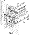
- the screen handling system includes a stinger assembly 34 that is capable of engaging and maneuvering a support member (e.g., a screen 30 - FIG. 3 ) against the rock face 26.
- the stinger assembly 34 includes a stinger pad 38 having an aperture 42, a finger gripper 46 that may engage (e.g., hook around a portion of) the mesh screen ( FIG. 3 ), and a stinger block 50 that supports the finger gripper cylinder 46 for movement.
- the finger gripper 46 is moveable along a stinger axis 54 between a retracted position ( FIG.
- the gripper 46 is part of an actuator subassembly 48.
- the gripper 46 is driven hydraulically between the retracted and the extended position.
- the gripper 46 includes a main body 62 that is at least partially supported within a bore 64 ( FIG. 2 ) of the stinger block 50, a head 66, and a neck 70 positioned between the main body 62 and the head 66.
- the head 66 has a convex or conical profile to facilitate movement of the head 66 through a wire segment of the screen 30 and subsequent gripping of the screen 30 via the head 66.
- the neck 70 has a reduced-diameter relative to the head 66, thereby allowing a portion of the head 66 (e.g., an outer periphery of the head 66) to engage and hold the mesh screen 30.
- the portion of the head 66 includes a shoulder 72 having a plurality of hooks 74 that extend rearwardly from the head 66 in a direction parallel to the stinger axis 54. Each hook 74 is configured to hook around a portion of the screen 30.
- the finger gripper 46 is moved to the extended position, enabling the head 66 to extend through and engage the screen 30.
- the finger gripper 46 may then be retracted along the stinger axis 54 until the portion of the screen 30 is secured between the head 66 of the finger gripper 46 and the front face 58 of the stinger pad 38.
- the head 66 protrudes beyond the front face 58 of the stringer pad 38 while the screen 30 is secured due to a mechanical interference with the screen 30 lodged in the neck 70.
- the screen 30 may be maneuvered into a desired position and orientation relative to the rock face 26.
- the stinger assembly 34 further includes a drive mechanism (e.g., hydraulic slew drive 78).
- the hydraulic slew drive mechanism 78 is supported by the stinger block 50 (as shown in FIG. 2 ) and includes a housing 82, a worm wheel 86 disposed within the housing 82, and a threaded shaft or worm gear 90 that engages and drives the worm wheel 86 for rotation about the stinger axis 54.
- the worm gear 90 includes helical teeth 92 that engage corresponding helical teeth 94 of the worm wheel 86.
- a gear ratio between the worm gear 90 and the worm wheel 86 determines a rotational output of a hydraulic motor 98 to the worm wheel 86.
- the worm gear 90 is driven by the hydraulic motor 98 about a motor axis 102 that is perpendicular to the stinger axis 54.
- the stinger pad 38 is coupled to the worm wheel 82 (e.g., via bolts 89) for co-rotation therewith.
- the slew drive mechanism 78 permits the worm wheel 82 (and therefore the stinger pad 38) to be continuously and completely rotated about the stinger axis 54 and may be rotated to any number of positions or orientations. Stated another way, the worm gear 86 can drive the worm wheel 82 (and therefore the stinger pad 38) through virtually infinite rotations. Since the screen 30 is forcibly held against the stinger pad 38 by the finger gripper 46, the screen 30 rotates with the stinger pad 38 and can be precisely oriented and/or positioned relative to the rock face 26.
- the stinger pad 38 When the hydraulic motor 98 is deactivated, the stinger pad 38 immediately stops rotating due to a fixed gear ratio between the worm wheel 86 and the worm gear 90 even though the screen may exert a reaction torque (e.g., due to rotational inertia) on the stinger pad 38 when stopped abruptly.
- the slew drive mechanism 78 provides a compact drive mechanism that permits the stinger assembly to have a shorter length than conventional screen handling devices. The compact length reduces the amount of weight that is supported in a cantilevered manner by the boom 14, thereby also reducing the counterweight needed to maintain balance for the feed assembly 10.
- the stinger assembly 34 is supported on the feed assembly 10 that is capable of extending and retracting the stinger assembly 34 along the stinger axis 54 relative to the mounting frame 18.
- a first rail system 110 couples the feed assembly 10 for translation relative to the mounting frame 18.
- a feed actuator e.g. a hydraulic cylinder 114 is coupled between the mounting frame 18 and the feed assembly 10, and is actuatable to move the feed assembly 10 along the first rail system 110 between a first position ( FIG. 7 ) and a second position ( FIG. 8 ). In the first position, the stinger assembly 34 may be spaced away from the rock face 26 ( FIG. 1 ).
- the feed actuator 114 can actuate the feed assembly 10 toward the second position at which the stinger assembly 34 is positioned adjacent the rock face 26. Placing the stinger assembly 34 against the mine face 26 (sometimes referred to as “stinging the face"), the feed assembly 10 is held stable against the rock face 26 to inhibit the screen handling system from moving relative to the rock face 26 during a drilling and bolting operation.
- the feed assembly 10 further includes a drill feed 118, consumable 122 (e.g., a drill bit, resin cartridge, bolt, etc.), and a second rail system 126 that supports the drill feed 118 for translational movement along drill axis 130.
- the drill feed 118 rotationally drives (e.g., via a motor) and advances a drill bit 122 into the rock face 26 as the drill feed 118 translates along the second rail system 126.
- a hydraulic actuator, belt drive, or some other linear actuator moves the drill feed 118 along the second rail system 126.
- the feed assembly 10 further includes a cable handler 134 that facilitates gathering and guiding drill feed cables (not shown) as the drill feed 118 translates.
- a cable handler 134 that facilitates gathering and guiding drill feed cables (not shown) as the drill feed 118 translates.
- the bolting assembly 1106 may include a stinger assembly 34 with the hydraulic slew drive mechanism 78, the drill feed 118, and the rock drill 122. Furthermore, the bolting assembly 1106 may include a carousel 1136 for holding various tools used during the drilling and bolting operation.
Landscapes
- Engineering & Computer Science (AREA)
- Mining & Mineral Resources (AREA)
- Structural Engineering (AREA)
- Life Sciences & Earth Sciences (AREA)
- General Life Sciences & Earth Sciences (AREA)
- Geochemistry & Mineralogy (AREA)
- Geology (AREA)
- Architecture (AREA)
- Civil Engineering (AREA)
- Earth Drilling (AREA)
- Load-Engaging Elements For Cranes (AREA)
- Manufacture And Refinement Of Metals (AREA)
Priority Applications (1)
| Application Number | Priority Date | Filing Date | Title |
|---|---|---|---|
| HRP20251648TT HRP20251648T1 (hr) | 2021-06-30 | 2022-06-30 | Sustav za rukovanje sitom |
Applications Claiming Priority (1)
| Application Number | Priority Date | Filing Date | Title |
|---|---|---|---|
| US202163216967P | 2021-06-30 | 2021-06-30 |
Publications (3)
| Publication Number | Publication Date |
|---|---|
| EP4112877A2 true EP4112877A2 (fr) | 2023-01-04 |
| EP4112877A3 EP4112877A3 (fr) | 2023-03-01 |
| EP4112877B1 EP4112877B1 (fr) | 2025-11-19 |
Family
ID=82492446
Family Applications (1)
| Application Number | Title | Priority Date | Filing Date |
|---|---|---|---|
| EP22182164.8A Active EP4112877B1 (fr) | 2021-06-30 | 2022-06-30 | Système du placement de la maille |
Country Status (11)
| Country | Link |
|---|---|
| US (1) | US12180835B2 (fr) |
| EP (1) | EP4112877B1 (fr) |
| AU (1) | AU2022204525A1 (fr) |
| CA (1) | CA3166168A1 (fr) |
| CL (1) | CL2022001791A1 (fr) |
| FI (1) | FI4112877T3 (fr) |
| HR (1) | HRP20251648T1 (fr) |
| MX (2) | MX2022008195A (fr) |
| PE (1) | PE20230097A1 (fr) |
| PL (1) | PL4112877T3 (fr) |
| ZA (1) | ZA202207134B (fr) |
Families Citing this family (2)
| Publication number | Priority date | Publication date | Assignee | Title |
|---|---|---|---|---|
| CN116988821B (zh) * | 2023-09-25 | 2024-02-09 | 湖南创远高新机械有限责任公司 | 一种挂网锚杆钻机 |
| CN118815520B (zh) * | 2024-09-10 | 2025-01-24 | 山东大学 | 一种避免锚杆钻头缠网装置 |
Family Cites Families (8)
| Publication number | Priority date | Publication date | Assignee | Title |
|---|---|---|---|---|
| US8137033B1 (en) * | 2009-08-03 | 2012-03-20 | J.H. Fletcher & Co. | Mesh handling system for an underground mining machine and related methods |
| US8956082B2 (en) * | 2012-10-23 | 2015-02-17 | 1311854 Ontario Limited | Rock bolting system, method of installing rock bolts, and flexible bolt centralizer |
| US9187873B2 (en) * | 2013-04-02 | 2015-11-17 | 1311854 Ontario Limited | Screen-handling system and method of installing screening on a rock face |
| AU2014200223B2 (en) | 2013-04-02 | 2017-04-13 | 1311854 Ontario Limited | Screen-handling system and method of installing screening on a rock face |
| CA2811722C (fr) | 2013-04-02 | 2015-09-01 | Yves Nelson | Systeme de manutention d'ecran et procede d'installation d'un ecran sur une paroi rocheuse |
| CA2900766C (fr) | 2014-04-17 | 2017-06-20 | Yves Nelson | Boulonneuse comportant un mecanisme d'alignement permettant de passer du forage au boulonnage |
| CL2016000682A1 (es) | 2015-12-10 | 2016-09-30 | Ncm Innovations Pty Ltd | Anclaje de roca de soporte de malla |
| AU2019200996B1 (en) | 2019-02-13 | 2020-05-07 | Geobrugg Ag | A method for mounting a roll of protective mesh material to an underground rock drilling machine, a method for attaching protective mesh material to a rock surface and a mounting device |
-
2022
- 2022-06-27 AU AU2022204525A patent/AU2022204525A1/en active Pending
- 2022-06-28 ZA ZA2022/07134A patent/ZA202207134B/en unknown
- 2022-06-29 US US17/853,599 patent/US12180835B2/en active Active
- 2022-06-29 MX MX2022008195A patent/MX2022008195A/es unknown
- 2022-06-29 CA CA3166168A patent/CA3166168A1/fr active Pending
- 2022-06-29 MX MX2026002744A patent/MX2026002744A/es unknown
- 2022-06-30 EP EP22182164.8A patent/EP4112877B1/fr active Active
- 2022-06-30 PL PL22182164.8T patent/PL4112877T3/pl unknown
- 2022-06-30 FI FIEP22182164.8T patent/FI4112877T3/fi active
- 2022-06-30 CL CL2022001791A patent/CL2022001791A1/es unknown
- 2022-06-30 PE PE2022001376A patent/PE20230097A1/es unknown
- 2022-06-30 HR HRP20251648TT patent/HRP20251648T1/hr unknown
Also Published As
| Publication number | Publication date |
|---|---|
| CA3166168A1 (fr) | 2022-12-30 |
| AU2022204525A1 (en) | 2023-01-19 |
| PE20230097A1 (es) | 2023-01-19 |
| US12180835B2 (en) | 2024-12-31 |
| EP4112877A3 (fr) | 2023-03-01 |
| HRP20251648T1 (hr) | 2026-02-13 |
| EP4112877B1 (fr) | 2025-11-19 |
| FI4112877T3 (fi) | 2026-01-14 |
| US20230003125A1 (en) | 2023-01-05 |
| PL4112877T3 (pl) | 2026-03-09 |
| ZA202207134B (en) | 2023-02-22 |
| CL2022001791A1 (es) | 2023-04-14 |
| MX2026002744A (es) | 2026-04-01 |
| MX2022008195A (es) | 2023-01-18 |
Similar Documents
| Publication | Publication Date | Title |
|---|---|---|
| EP4112877A2 (fr) | Système du placement de la maille | |
| AU2020202327B2 (en) | Wireline system and methods of using same | |
| US6752043B2 (en) | Vise apparatus | |
| US7458244B2 (en) | Feeding unit and method for feeding an element to a treatment unit | |
| AT520768A2 (de) | Elektrische Bohr- und Verankerungsvorrichtung | |
| GB2587179A (en) | Downhole internal pipe cutting method and apparatus | |
| CA2414091C (fr) | Procede pour separer des joints entre composants de forage et perforatrice de roches | |
| US9187873B2 (en) | Screen-handling system and method of installing screening on a rock face | |
| CN213980707U (zh) | 可自动装卸钻杆钻机的夹持卸扣装置 | |
| EP1745871A1 (fr) | Systeme ameliore de rivetage automatique | |
| EP1238726B1 (fr) | Dispositif de rotation pour une machine de pose de rivets | |
| AU2014200223B2 (en) | Screen-handling system and method of installing screening on a rock face | |
| CN217538746U (zh) | 锚杆部和工程机械 | |
| CN1304723C (zh) | 用于水平钻孔中的夹具设备及夹持钻孔元件的方法 | |
| CN218644233U (zh) | 一种钎杆连接装置及使用该装置的凿岩机 | |
| US5758399A (en) | Tool turret with torque overload protection | |
| CA2811722A1 (fr) | Systeme de manutention d'ecran et procede d'installation d'un ecran sur une paroi rocheuse | |
| CN212985123U (zh) | 一种钻锚一体式推进梁结构 | |
| JP3004459B2 (ja) | シールド掘進機用ボルト自動供給装置 | |
| CN2695153Y (zh) | 锁紧式手紧钻夹头 | |
| JPH10306698A (ja) | セグメント組立装置におけるボルトナット供給装置 | |
| WO2003102352A1 (fr) | Assemblage d'appareil de forage pour forage de roches | |
| JP2944818B2 (ja) | ボルト締結装置へのボルト・ナット受渡し方法 | |
| CN1879992A (zh) | 钻孔装置 | |
| JPH0276645A (ja) | ボルト締付装置 |
Legal Events
| Date | Code | Title | Description |
|---|---|---|---|
| REG | Reference to a national code |
Ref country code: HR Ref legal event code: TUEP Ref document number: P20251648T Country of ref document: HR |
|
| PUAI | Public reference made under article 153(3) epc to a published international application that has entered the european phase |
Free format text: ORIGINAL CODE: 0009012 |
|
| STAA | Information on the status of an ep patent application or granted ep patent |
Free format text: STATUS: THE APPLICATION HAS BEEN PUBLISHED |
|
| AK | Designated contracting states |
Kind code of ref document: A2 Designated state(s): AL AT BE BG CH CY CZ DE DK EE ES FI FR GB GR HR HU IE IS IT LI LT LU LV MC MK MT NL NO PL PT RO RS SE SI SK SM TR |
|
| PUAL | Search report despatched |
Free format text: ORIGINAL CODE: 0009013 |
|
| AK | Designated contracting states |
Kind code of ref document: A3 Designated state(s): AL AT BE BG CH CY CZ DE DK EE ES FI FR GB GR HR HU IE IS IT LI LT LU LV MC MK MT NL NO PL PT RO RS SE SI SK SM TR |
|
| RIC1 | Information provided on ipc code assigned before grant |
Ipc: E21D 11/40 20060101ALN20230125BHEP Ipc: E21D 21/00 20060101ALI20230125BHEP Ipc: E21D 20/00 20060101AFI20230125BHEP |
|
| STAA | Information on the status of an ep patent application or granted ep patent |
Free format text: STATUS: REQUEST FOR EXAMINATION WAS MADE |
|
| 17P | Request for examination filed |
Effective date: 20230427 |
|
| RBV | Designated contracting states (corrected) |
Designated state(s): AL AT BE BG CH CY CZ DE DK EE ES FI FR GB GR HR HU IE IS IT LI LT LU LV MC MK MT NL NO PL PT RO RS SE SI SK SM TR |
|
| STAA | Information on the status of an ep patent application or granted ep patent |
Free format text: STATUS: EXAMINATION IS IN PROGRESS |
|
| 17Q | First examination report despatched |
Effective date: 20250221 |
|
| GRAP | Despatch of communication of intention to grant a patent |
Free format text: ORIGINAL CODE: EPIDOSNIGR1 |
|
| STAA | Information on the status of an ep patent application or granted ep patent |
Free format text: STATUS: GRANT OF PATENT IS INTENDED |
|
| INTG | Intention to grant announced |
Effective date: 20250612 |
|
| GRAS | Grant fee paid |
Free format text: ORIGINAL CODE: EPIDOSNIGR3 |
|
| GRAA | (expected) grant |
Free format text: ORIGINAL CODE: 0009210 |
|
| STAA | Information on the status of an ep patent application or granted ep patent |
Free format text: STATUS: THE PATENT HAS BEEN GRANTED |
|
| AK | Designated contracting states |
Kind code of ref document: B1 Designated state(s): AL AT BE BG CH CY CZ DE DK EE ES FI FR GB GR HR HU IE IS IT LI LT LU LV MC MK MT NL NO PL PT RO RS SE SI SK SM TR |
|
| REG | Reference to a national code |
Ref country code: CH Ref legal event code: F10 Free format text: ST27 STATUS EVENT CODE: U-0-0-F10-F00 (AS PROVIDED BY THE NATIONAL OFFICE) Effective date: 20251119 Ref country code: GB Ref legal event code: FG4D |
|
| REG | Reference to a national code |
Ref country code: DE Ref legal event code: R096 Ref document number: 602022025137 Country of ref document: DE |
|
| REG | Reference to a national code |
Ref country code: IE Ref legal event code: FG4D |
|
| P01 | Opt-out of the competence of the unified patent court (upc) registered |
Free format text: CASE NUMBER: UPC_APP_0016631_4112877/2025 Effective date: 20251210 |
|
| REG | Reference to a national code |
Ref country code: FI Ref legal event code: FGE |
|
| REG | Reference to a national code |
Ref country code: SE Ref legal event code: TRGR |
|
| REG | Reference to a national code |
Ref country code: HR Ref legal event code: T1PR Ref document number: P20251648 Country of ref document: HR |
|
| REG | Reference to a national code |
Ref country code: NL Ref legal event code: MP Effective date: 20251119 |
|
| PG25 | Lapsed in a contracting state [announced via postgrant information from national office to epo] |
Ref country code: ES Free format text: LAPSE BECAUSE OF FAILURE TO SUBMIT A TRANSLATION OF THE DESCRIPTION OR TO PAY THE FEE WITHIN THE PRESCRIBED TIME-LIMIT Effective date: 20251119 |
|
| REG | Reference to a national code |
Ref country code: LT Ref legal event code: MG9D |
|
| PG25 | Lapsed in a contracting state [announced via postgrant information from national office to epo] |
Ref country code: AT Free format text: LAPSE BECAUSE OF FAILURE TO SUBMIT A TRANSLATION OF THE DESCRIPTION OR TO PAY THE FEE WITHIN THE PRESCRIBED TIME-LIMIT Effective date: 20251119 |
|
| REG | Reference to a national code |
Ref country code: AT Ref legal event code: MK05 Ref document number: 1858978 Country of ref document: AT Kind code of ref document: T Effective date: 20251119 |
|
| PG25 | Lapsed in a contracting state [announced via postgrant information from national office to epo] |
Ref country code: NL Free format text: LAPSE BECAUSE OF FAILURE TO SUBMIT A TRANSLATION OF THE DESCRIPTION OR TO PAY THE FEE WITHIN THE PRESCRIBED TIME-LIMIT Effective date: 20251119 |
|
| PG25 | Lapsed in a contracting state [announced via postgrant information from national office to epo] |
Ref country code: RS Free format text: LAPSE BECAUSE OF FAILURE TO SUBMIT A TRANSLATION OF THE DESCRIPTION OR TO PAY THE FEE WITHIN THE PRESCRIBED TIME-LIMIT Effective date: 20260219 |
|
| PG25 | Lapsed in a contracting state [announced via postgrant information from national office to epo] |
Ref country code: IS Free format text: LAPSE BECAUSE OF FAILURE TO SUBMIT A TRANSLATION OF THE DESCRIPTION OR TO PAY THE FEE WITHIN THE PRESCRIBED TIME-LIMIT Effective date: 20260319 |
|
| PG25 | Lapsed in a contracting state [announced via postgrant information from national office to epo] |
Ref country code: PT Free format text: LAPSE BECAUSE OF FAILURE TO SUBMIT A TRANSLATION OF THE DESCRIPTION OR TO PAY THE FEE WITHIN THE PRESCRIBED TIME-LIMIT Effective date: 20260319 |
|
| PG25 | Lapsed in a contracting state [announced via postgrant information from national office to epo] |
Ref country code: LV Free format text: LAPSE BECAUSE OF FAILURE TO SUBMIT A TRANSLATION OF THE DESCRIPTION OR TO PAY THE FEE WITHIN THE PRESCRIBED TIME-LIMIT Effective date: 20251119 |