EP4112932B1 - Compresseur à piston et procédé de fonctionnement d'un compresseur à piston - Google Patents
Compresseur à piston et procédé de fonctionnement d'un compresseur à piston Download PDFInfo
- Publication number
- EP4112932B1 EP4112932B1 EP22180868.6A EP22180868A EP4112932B1 EP 4112932 B1 EP4112932 B1 EP 4112932B1 EP 22180868 A EP22180868 A EP 22180868A EP 4112932 B1 EP4112932 B1 EP 4112932B1
- Authority
- EP
- European Patent Office
- Prior art keywords
- lubricant
- lubricating film
- lubricating
- piston
- amount
- Prior art date
- Legal status (The legal status is an assumption and is not a legal conclusion. Google has not performed a legal analysis and makes no representation as to the accuracy of the status listed.)
- Active
Links
Images


Classifications
-
- F—MECHANICAL ENGINEERING; LIGHTING; HEATING; WEAPONS; BLASTING
- F04—POSITIVE - DISPLACEMENT MACHINES FOR LIQUIDS; PUMPS FOR LIQUIDS OR ELASTIC FLUIDS
- F04B—POSITIVE-DISPLACEMENT MACHINES FOR LIQUIDS; PUMPS
- F04B39/00—Component parts, details, or accessories, of pumps or pumping systems specially adapted for elastic fluids, not otherwise provided for in, or of interest apart from, groups F04B25/00 - F04B37/00
- F04B39/02—Lubrication
- F04B39/0207—Lubrication with lubrication control systems
-
- F—MECHANICAL ENGINEERING; LIGHTING; HEATING; WEAPONS; BLASTING
- F04—POSITIVE - DISPLACEMENT MACHINES FOR LIQUIDS; PUMPS FOR LIQUIDS OR ELASTIC FLUIDS
- F04B—POSITIVE-DISPLACEMENT MACHINES FOR LIQUIDS; PUMPS
- F04B39/00—Component parts, details, or accessories, of pumps or pumping systems specially adapted for elastic fluids, not otherwise provided for in, or of interest apart from, groups F04B25/00 - F04B37/00
- F04B39/02—Lubrication
- F04B39/0223—Lubrication characterised by the compressor type
- F04B39/0276—Lubrication characterised by the compressor type the pump being of the reciprocating piston type, e.g. oscillating, free-piston compressors
-
- F—MECHANICAL ENGINEERING; LIGHTING; HEATING; WEAPONS; BLASTING
- F04—POSITIVE - DISPLACEMENT MACHINES FOR LIQUIDS; PUMPS FOR LIQUIDS OR ELASTIC FLUIDS
- F04B—POSITIVE-DISPLACEMENT MACHINES FOR LIQUIDS; PUMPS
- F04B39/00—Component parts, details, or accessories, of pumps or pumping systems specially adapted for elastic fluids, not otherwise provided for in, or of interest apart from, groups F04B25/00 - F04B37/00
- F04B39/02—Lubrication
- F04B39/0284—Constructional details, e.g. reservoirs in the casing
- F04B39/0292—Lubrication of pistons or cylinders
-
- F—MECHANICAL ENGINEERING; LIGHTING; HEATING; WEAPONS; BLASTING
- F04—POSITIVE - DISPLACEMENT MACHINES FOR LIQUIDS; PUMPS FOR LIQUIDS OR ELASTIC FLUIDS
- F04B—POSITIVE-DISPLACEMENT MACHINES FOR LIQUIDS; PUMPS
- F04B39/00—Component parts, details, or accessories, of pumps or pumping systems specially adapted for elastic fluids, not otherwise provided for in, or of interest apart from, groups F04B25/00 - F04B37/00
- F04B39/04—Measures to avoid lubricant contaminating the pumped fluid
- F04B39/041—Measures to avoid lubricant contaminating the pumped fluid sealing for a reciprocating rod
- F04B39/042—Measures to avoid lubricant contaminating the pumped fluid sealing for a reciprocating rod sealing being provided on the piston
-
- F—MECHANICAL ENGINEERING; LIGHTING; HEATING; WEAPONS; BLASTING
- F04—POSITIVE - DISPLACEMENT MACHINES FOR LIQUIDS; PUMPS FOR LIQUIDS OR ELASTIC FLUIDS
- F04B—POSITIVE-DISPLACEMENT MACHINES FOR LIQUIDS; PUMPS
- F04B49/00—Control, e.g. of pump delivery, or pump pressure of, or safety measures for, machines, pumps, or pumping installations, not otherwise provided for, or of interest apart from, groups F04B1/00 - F04B47/00
- F04B49/06—Control using electricity
-
- F—MECHANICAL ENGINEERING; LIGHTING; HEATING; WEAPONS; BLASTING
- F04—POSITIVE - DISPLACEMENT MACHINES FOR LIQUIDS; PUMPS FOR LIQUIDS OR ELASTIC FLUIDS
- F04B—POSITIVE-DISPLACEMENT MACHINES FOR LIQUIDS; PUMPS
- F04B51/00—Testing machines, pumps, or pumping installations
-
- F—MECHANICAL ENGINEERING; LIGHTING; HEATING; WEAPONS; BLASTING
- F04—POSITIVE - DISPLACEMENT MACHINES FOR LIQUIDS; PUMPS FOR LIQUIDS OR ELASTIC FLUIDS
- F04B—POSITIVE-DISPLACEMENT MACHINES FOR LIQUIDS; PUMPS
- F04B2201/00—Pump parameters
- F04B2201/04—Carter parameters
- F04B2201/0404—Lubricating oil condition
-
- F—MECHANICAL ENGINEERING; LIGHTING; HEATING; WEAPONS; BLASTING
- F04—POSITIVE - DISPLACEMENT MACHINES FOR LIQUIDS; PUMPS FOR LIQUIDS OR ELASTIC FLUIDS
- F04B—POSITIVE-DISPLACEMENT MACHINES FOR LIQUIDS; PUMPS
- F04B2201/00—Pump parameters
- F04B2201/08—Cylinder or housing parameters
-
- F—MECHANICAL ENGINEERING; LIGHTING; HEATING; WEAPONS; BLASTING
- F04—POSITIVE - DISPLACEMENT MACHINES FOR LIQUIDS; PUMPS FOR LIQUIDS OR ELASTIC FLUIDS
- F04B—POSITIVE-DISPLACEMENT MACHINES FOR LIQUIDS; PUMPS
- F04B53/00—Component parts, details or accessories not provided for in, or of interest apart from, groups F04B1/00 - F04B23/00 or F04B39/00 - F04B47/00
- F04B53/18—Lubricating
Definitions
- the invention relates to a lubrication system for a piston compressor, for applying a lubricant to a cylinder surface of a cylinder of the piston compressor, in which cylinder a piston is movable back and forth, wherein a lubrication system control unit is provided for controlling the amount of lubricant to be introduced.
- the invention further relates to a piston compressor with a lubrication system and a method for operating a piston compressor with at least one cylinder in which a piston is moved back and forth, wherein a lubricant is supplied to a cylinder surface of the at least one cylinder by means of a lubrication system, and wherein the amount of the supplied lubricant is controlled by a lubrication system control unit.
- each cylinder has one or more lubrication points through which lubricant can be introduced into the cylinder.
- the lubrication points are usually supplied with lubricant from a central lubrication system.
- the most precise metering of lubricant into the cylinders is crucial for reliable operation.
- An insufficient amount of lubricant leads to increased wear on the moving components of the compressor, particularly on the piston rings or packing rings of the sealing rings used to seal the piston rod. Increased wear subsequently leads to a reduced service life of these components and thus to lower compressor availability.
- an excessive amount of lubricant generally leads to a reduced service life of components such as compressor valves due to an oil sticking effect, as well as to a reduced service life of downstream devices such as catalytic converters.
- high amounts of lubricant naturally lead to increased operating costs due to lubricant consumption as well as higher investment costs because additional equipment such as special separators are required to remove excess lubricant from the compressed process stream.
- Conventional lubrication systems are usually based on a specified lubricant quantity for the respective piston machines. These specified lubricant quantities are typically provided by the compressor manufacturers depending on the compressor type, size, and process parameters and are based on empirical data or simplified calculation models. Due to uncertainties in these calculation models and to cover all designs and operating conditions, Compressors are usually provided with safety factors that are conservatively selected, so that more lubricant is usually added than necessary. Such "overlubrication" of the cylinders during operation is, of course, disadvantageous and therefore undesirable for the operator of a piston compressor for the reasons mentioned above. A well-known lubrication system is described in the document DE 600 26 599 T2 revealed.
- the object is achieved with the lubrication system mentioned above in that at least one lubricant sensor is provided for detecting a lubricating film measurement variable representative of the lubricating film thickness on the cylinder bore surface of the cylinder, that the lubrication system control unit is designed to operate the lubrication system at least once in a predetermined calibration operating mode during operation of the reciprocating compressor, to determine a lubricating film condition value based on the lubricating film measurement variable detected during the calibration operating mode, and to control the amount of lubricant to be introduced depending on the determined lubricating film condition value after the calibration operating mode has ended during operation of the reciprocating compressor.
- the lubricant sensor is an ultrasonic sensor, with a temporal resolution of the lubricant sensor preferably being 0.01° to 5° crank angle. This enables simple detection of the lubricant film measurement variable without requiring direct access to the cylinder bore.
- An ultrasonic sensor can, for example, be easily mounted on the outside of an existing cylinder.
- the lubrication system control unit is designed to use a sensor value of the lubricating film measurement variable to determine the lubricating film condition value, which is detected during a piston stroke of the piston at a time when a piston ring of the piston is located in the sensor area of the lubricant sensor, preferably a minimum value of the lubricating film measurement variable detected during the piston stroke.
- the current lubricating film thickness in the area of a piston ring can be determined and the required amount of lubricant can be determined based on this.
- the lubrication system is configured for intermittently introducing lubricant into the cylinder, preferably as a pump-to-point system, a divider-block system, or a common rail system.
- the lubrication system control unit is configured to control the lubricant quantity by changing the frequency and/or injection quantity of each injection of the intermittent lubricant injection. This allows proven lubrication systems to be used and calibrated accordingly.
- the lubrication system control unit is advantageously configured to repeat the calibration operating mode in a specified cycle to update the lubricating film condition value and adjust the lubricant quantity to the updated lubricating film condition value. This allows changes occurring during operation to be taken into account, which may require a greater or lesser amount of lubricant, such as piston ring wear.
- the duration of the calibration operating mode is at least ten, preferably at least one hundred, particularly preferably at least one thousand crankshaft revolutions of the reciprocating compressor or an equivalent time. This provides sufficient time to adjust and evaluate various states of the lubricating film.
- the lubrication system control unit is designed to determine a maximum value and a minimum value in a time profile of the lubricating film measurement variable recorded during the at least two time periods and to determine therefrom the lubricating film condition value for controlling the lubricant quantity.
- a first time period with a predetermined duration and a subsequent second time period with a predetermined duration are defined, and the lubricant quantity introduced during the first time period is defined such that a completely wetted lubricating film is established on the cylinder running surface, and the lubricant quantity introduced during the second time period is defined such that dry running occurs on the cylinder running surface.
- the duration of the first time period is preferably at least five crankshaft revolutions, and the lubricant quantity introduced during the first time period is preferably 90-200% of a lubricant quantity specified by the compressor manufacturer.
- the duration of the second time period is preferably at least five crankshaft revolutions, and the lubricant quantity introduced during the second
- the lubricant quantity applied during the time range is preferably 0% of the lubricant quantity specified by the compressor manufacturer. This simulates various lubricant film conditions and is used to determine a representative, generally valid lubricant film condition value.
- the lubrication system control unit is designed to determine a difference value between the determined maximum value and the determined minimum value, to determine a lubricating film limit value from the maximum value and the determined difference value, and to use the lubricating film limit value as the lubricating film condition value.
- the lubrication system control unit is preferably further designed to control the lubrication system to introduce the lubricant during operation of the piston compressor after the end of the calibration operating mode if the lubricating film measurement value lies in a lubrication system activation range between the minimum value and the lubricating film limit value. This creates a differential evaluation method that is essentially independent of the recorded absolute values of the recorded lubricating film measurement value, and provides a simple indicator for activating the lubricant introduction.
- the lubrication system preferably also includes a lubricant quantity detection unit for detecting the amount of lubricant supplied to the lubrication point, and the lubrication system control unit is configured to compare the measured lubricant film value obtained from the lubricant film sensor and the lubricant quantity obtained from the lubricant quantity detection unit in order to check the two values for consistency and/or to detect a leak in the lubrication system.
- This allows the function of the lubricant sensor to be tested and leaks in the lubricant lines to be detected. Based on this, certain actions, such as shutting down the compressor or switching the lubrication system to conventional overlubrication, can be performed, thereby increasing operational reliability.
- the invention is further achieved by a method in that by means of at least one lubricant sensor, which is an ultrasonic sensor, a lubricating film measurement variable representative of a lubricating film thickness of a lubricating film on the cylinder running surface of the cylinder is detected, in that the lubrication system is operated by the lubrication system control unit at least once in a predetermined calibration operating mode during operation of the piston compressor, wherein a lubricating film condition value is determined on the basis of the lubricating film measurement variable detected during the execution of the calibration operating mode, and in that the lubrication system control unit, after completion of the calibration operating mode, of the piston compressor controls the amount of lubricant to be introduced depending on the determined lubricating film condition value.
- a lubricant sensor which is an ultrasonic sensor
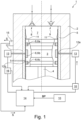
- Fig.1 is a simplified sectional view through a cylinder 2 of a piston compressor 1.
- a piston 3 is arranged in a known manner and can move back and forth in the cylinder between a top dead center TDC and a bottom dead center BDC.
- the piston 3 can be driven in a known manner by a crankshaft (not shown) via a push rod (not shown), a crosshead (not shown) and a piston rod 4.
- a crankshaft not shown
- a push rod not shown
- a crosshead not shown
- piston rod 4 a piston rod 4
- a cylinder sleeve 5 a so-called liner, is arranged in the cylinder 2, on the inner circumferential surface of which a cylinder running surface for the piston 3 is formed.
- a piston compressor 1 can, of course, have several cylinders 2, in each of which a piston 3 can be moved back and forth, wherein the plurality of pistons 3 can be driven by a common crankshaft.
- One or more piston rings 6 can be provided on the piston 3, which are arranged in suitable circumferential grooves on the circumferential surface of the piston 3.
- a piston ring 6 is generally understood to mean piston rings with various functions.
- a piston ring 6 can be designed as a sealing ring, a support ring, or a scraper ring.
- a sealing ring is designed, for example, to seal against a differential pressure, while a The support ring typically does not have a sealing effect and is designed to support the load of the piston 3 on the cylinder liner.
- a scraper ring is designed to scrape the lubricating film from the cylinder bore.
- piston 3 rather, for example, only one piston ring 6 could be provided, for example in the form of a sealing ring.
- three piston rings 6a, 6b, 6c are provided, with the first and third piston rings 6a, 6c being designed as sealing rings and the second piston ring 6b being designed as a support ring.
- piston rings 6 could also be provided, e.g. an oil control ring. It can be seen that the support ring 6b has a greater width (in the axial direction) than the sealing rings 6a, 6c, which is usually the case.
- the groove in the piston 3, in which the support ring 6b is arranged is designed such that the support ring 6b rests directly on the groove base.
- the support ring 6b is therefore, in contrast to the sealing rings 6a, 6c, essentially immobile in the radial direction in order to be able to better support the load of the piston 3.
- the sealing rings 6a, 6c are radially movable in the respective grooves in order to achieve a better seal.
- a piston ring 6 can, of course, also have a certain radial projection over the piston 3, which for the sake of simplicity is Fig.1 is not shown.
- a compression chamber 7 is formed in a known manner, delimited by the piston 3, in which a suction valve 8 and a pressure valve 9 are arranged.
- a gaseous medium to be compressed for example air or a process gas, can be sucked into the compression chamber 7 via the suction valve 8.
- the medium is compressed in the compression chamber 7 and discharged from the compression chamber 7 via the pressure valve 9.
- the suction valve 8 and the pressure valve 9 are in Fig.1 are only indicated as schematic circuit symbols and can be designed in different ways.
- suction valves 8 and pressure valves 9 can also be provided on the cylinder.
- the suction valve 8 and the pressure valve 9 do not necessarily have to be arranged on the end face of the cylinder 2, but could, for example, also be provided on the circumferential surface of the cylinder 2 in the compression chamber 7.
- the suction valve 8 and the pressure valve 9 can be designed as known automatic ring valves, wherein, if necessary, a lifting gripper can also be provided to keep the valves open.
- the lifting gripper can be controlled by a suitable compressor control unit 10 to regulate the capacity of the compressor 1.
- the piston compressor 1 further comprises a lubrication system for lubricating at least one cylinder 2.
- the lubrication system comprises at least one lubrication point 12 for introducing a lubricant into the cylinder 2.
- the lubricant forms a lubricating film 11 in the cylinder 2 in order to minimize the friction between the components moving relative to one another, in particular between the piston 3 or piston rings 6 and the cylinder running surface.
- lubrication points 12 can of course also be provided, which can be arranged, for example, at a distance from one another in the axial direction and/or in the circumferential direction on the cylinder 2, as in Fig.1 by the lubrication points 12a, 12b.
- the lubricant is introduced via the lubrication point 12 during the compression stroke and/or the expansion stroke, for example, before the respective piston ring 6 reaches the lubrication point 12, while the piston ring 6 is located in the area of the lubrication point 12, or possibly even after the respective piston ring 6 has passed the lubrication point 12.
- the time of introduction depends essentially on the lubrication system used.
- a “divider-block” system provides a central delivery unit for delivering the lubricant and a so-called “divider block” for distributing the lubricant to the lubrication points 12 of the cylinders 2.
- the amount of lubricant delivered by the central delivery unit is fed to a so-called “divider block,” divided therein, and delivered to the individual lubrication points 12.
- the lubricant is generally introduced into the cylinder 2 intermittently via individual injections.
- the amount of lubricant to be introduced is controlled by a corresponding control of the central delivery unit.
- the delivery rate can be controlled via the speed and/or, if necessary, via the piston stroke.
- a change in the lubricant quantity during operation of the compressor 1 can be achieved, for example, by changing the frequency of the intermittent individual injections of the lubricant, for example, by changing the pump speed.
- a change in the lubricant quantity can only be made in a constant ratio for all available lubrication points 12. Different lubricant quantities for different lubrication points 12 or different cylinders 2 are generally not possible.
- each lubrication point 12 or each cylinder 2 is assigned its own delivery unit, e.g. a piston pump.
- a piston pump e.g. a piston pump
- a corresponding amount of lubricant is delivered to the assigned lubrication point 12, usually intermittently via individual injections.
- the delivery units, in particular the piston pumps, are generally driven by a common camshaft.
- a change in the lubricant quantity during operation of the compressor 1 can be achieved, for example, by changing the frequency of the individual injections of lubricant by adjusting the speed of the camshaft.
- the delivery quantities can also be changed separately, for example, by an adjustable stroke of the piston pumps. This allows the lubricant quantity to be individually adjusted at each lubrication point 12 or for each cylinder 2.
- suitable adjustment devices can be provided on the delivery units, for example.
- the adjustment device can, for example, be designed for manually adjusting the stroke of a piston pump or a suitable actuator can be provided for adjusting the stroke so that the amount of lubricant introduced per injection can be changed.
- lubricant is pumped into a pressure accumulator by a high-pressure pump and can be individually supplied from the pressure accumulator to each lubrication point 12 or each cylinder 2 via pressure lines using electrically controlled injectors.
- the lubricant quantity can be varied not only by changing the frequency of the intermittent injection, but also by very precisely and variably controlling the amount of lubricant injected per injection.
- the timing of injection at each lubrication point 12 or at each cylinder 2 can be individually adjusted and essentially independent of the high-pressure pump operation (as long as sufficient pressure is present in the pressure accumulator). This makes it possible, for example, for a piston compressor 1, whose pistons 3 have multiple piston rings 6, to perform multiple injections within one piston stroke, so that a specific amount of lubricant can be specifically supplied to each piston ring 6.
- the control of the lubricant injection for example the time of an injection and/or the amount of lubricant per injection and/or the frequency of the injections, is usually carried out via a suitable lubrication system control unit 14.
- the lubrication system control unit 14 can be designed as separate hardware and/or software or can, for example, also be part of a higher-level control unit such as the compressor control unit 10.
- Fig.1 A "common rail" system is shown merely as an example, wherein an electrically controllable injector 13 is provided for each lubrication point 12, which can be designed, for example, as an electromagnetic injector or as a piezo injector.
- the injectors are connected to a central lubrication system control unit 14 via a suitable communication connection, for example via electrical lines.
- a pressure accumulator and a high-pressure pump are also provided, although for the sake of simplicity, these are not shown in Fig.1 are not shown.
- the high-pressure pump is preferably also controlled by the lubrication system control unit 14.
- the lubrication system control unit 14 can, for example, communicate with a compressor control unit 10 in order to obtain operating parameters BP of the piston compressor 1 that are relevant for controlling the lubrication system.
- Such operating parameters BP can, for example, contain current data about the operating state of the compressor 1, for example a load signal L, a speed signal N, a crank angle signal °KW, lubricant temperature T, etc.
- the lubrication system control unit 14 can take the operating parameters BP into account when controlling the lubrication system.
- the present invention provides for automatic calibration of the lubrication system, whereby the lubricant quantity can be adjusted to the actual requirement.
- at least one lubricant sensor 15 is provided in the lubrication system for detecting a lubricant film measurement variable S representative of a lubricant film thickness of the lubricant film 11 on the cylinder bore of cylinder 2.
- the lubricant film measurement variable S is essentially a measure of the lubricant film thickness of the lubricant film 11 on the cylinder bore in a sensor area of the lubricant sensor 15.
- the lubricant sensor 15 is connected to the lubricant control unit 14 via a suitable communication connection in order to transmit the lubricant film measurement variable S to the lubricant control unit 14, for example via suitable electrical measuring lines.
- An acoustic sensor, in particular an ultrasonic sensor, is provided as the lubricant sensor 15.
- the lubricant sensor 15 can, for example, be arranged at a suitable location on the outside of the cylinder 2.
- the lubricant sensor 15 is arranged in the axial direction such that each piston ring 6 of the piston 3 is located in the sensor area of the lubricant sensor 15 once per piston stroke, so that a lubricant film thickness can be detected in the area of each piston ring 6.
- Several lubricant sensors 15 can also be arranged on the cylinder 2 at a distance from one another in the circumferential direction and/or in the axial direction. This can be particularly advantageous for large compressors in order to cover a sufficiently large area of the cylinder running surface of the cylinder 2.
- the temporal resolution of the lubricant sensor 15, in particular the ultrasonic sensor, for detecting the lubricant film measurement variable S can be, for example, 0.01° to 5° crank angle.
- the lubrication system control unit 14 is designed to operate the lubrication system at least once in a predetermined calibration operating mode during operation of the piston compressor 1 and to determine a lubricating film condition value SZ based on the lubricating film measurement variable S detected during the calibration operating mode. After the calibration operating mode has ended, i.e., during normal operation of the lubrication system during operation of the piston compressor 1, the lubrication system control unit 14 controls the amount of lubricant to be introduced depending on the determined lubricating film condition value SZ.
- the lubrication system is preferably designed for the intermittent introduction of lubricant, preferably as a pump-to-point system, a divider-block system, or a common-rail system.
- the lubrication system control unit 14 can adjust the lubricant quantity depending on the determined lubricating film condition value SZ, for example, by changing the frequency of the intermittent introduction of the lubricant and thereby reduce the lubricant quantity compared to the manufacturer's specification.
- the (total) lubricant quantity introduced into the cylinder 2 can, if necessary, additionally or alternatively to the frequency change, also be changed by changing the lubricant quantity per injection of the injector 13.
- a change in the frequency can be achieved, as mentioned, for example, by increasing the speed of the feed pump(s) of the respective lubrication system.
- a sensor value Pi of the lubricating film measured variable S is used, which is recorded during a piston stroke of the piston 3 at a time when a piston ring 6 of the piston 3 is located in the sensor area of the lubricant sensor 15.
- the minimum value of the lubricating film measured variable S is used in each case, as in Fig.2 is shown.
- Fig.2 An example of the curve of the recorded lubricating film measurement variable S of a lubricant sensor 15 over the crank angle °KW between the top dead center TDC and the bottom dead center BDC of the piston 3 during normal operation of the piston compressor 1 (and the lubrication system) is shown.
- the piston 3 corresponds to the design according to Fig.1 and has three piston rings 6a, 6b, 6c. Of course, more or fewer piston rings 6 are provided.
- the curve shown corresponds to the measurement signal of the lubricant sensor 15 over the crank angle.
- a characteristic temporal course of the lubricating film measured variable S results depending on the number i of piston rings 6i, which can be used as a measure of the lubricating film thickness of the lubricating film 11 on the cylinder running surface of the cylinder 2.
- the curve has a local minimum for each piston ring 6i, which is proportional to the thickness of the lubricating film 11 on the cylinder surface when the respective piston ring 6i is located in the sensor range of the lubricant sensor 15.
- these are the minimum values Pa, Pb, Pc, which are generally referred to as PEAK values Pi within the scope of the invention.
- the assignment of the PEAK values Pa, Pb, Pc to the respective piston ring 6a, 6b, 6c results from their arrangement on the piston 3.
- PEAK values Pa, Pb, Pc (generally Pi) can now be used according to the invention in a calibration operating mode of the lubrication system to determine the lubricating film condition value SZ, as described below with reference to Fig.3a +3b is explained.
- each lubricant sensor 15 could of course also be provided in the lubrication system in order to enable redundant detection of the lubricating film measured variable S.
- the lubricant sensors 15 can, for example, be arranged at a certain angle in the circumferential direction on the cylinder 2 and/or can be arranged at a certain angle in the axial direction on the cylinder 2.
- each lubricant sensor 15 is arranged such that all available piston rings 6i of the piston 3 are located in the sensor range of the respective lubricant sensor 15 at one time during a piston stroke.
- Two lubricant sensors 15 with different positions in the circumferential direction and the same axial positions on the cylinder 2 would, for example, result in qualitatively identical curves of the lubricating film measured variable S, which, however, could differ quantitatively due to the locally different lubricating film thickness of the lubricating film 11.
- the PEAK values Pi would, however, be at the same crank angle position.
- two lubricant sensors 15 with different positions in the axial direction and identical positions in the circumferential direction would, for example, result in qualitatively and quantitatively different curves of the lubricant film measured variable S.
- the PEAK values Pi would be located at different crank angle positions.
- the advantageous differential evaluation method of the PEAK value curves would compensate for the different absolute values of the PEAK values Pi.
- the PEAK values Pi can, for example, be recorded once in each crankshaft revolution or once in each piston stroke and stored in the lubrication system control unit 14. In principle, however, it may also be sufficient if the PEAK values Pi is not recorded continuously, i.e. not for each crankshaft revolution or each piston stroke and stored for the evaluation of the time course, but that the PEAK values Pi are recorded, for example, intermittently, with a fixed interruption duration of a few crankshaft revolutions or, for example, a time of 1 to 60 seconds.
- Fig.3b a time course of the lubricant quantity introduced into cylinder 2 during the calibration operating mode over the crankshaft revolutions of compressor 1.
- Fig.3a Using the example of the first piston ring 6a, a temporal progression of the stored PEAK values Pa over the crankshaft revolutions of the compressor 1 is shown, which changes due to the introduced lubricant quantity according to Fig.3b
- the duration of the calibration operating mode can be, for example, at least ten, preferably at least one hundred, particularly preferably at least one thousand crankshaft revolutions of the piston compressor 1. Since the crankshaft revolutions are proportional to time, time can in principle also be plotted on the abscissa.
- the calibration operating mode is performed at least once during operation of the piston compressor 1, for example, after a run-in phase during initial commissioning or after a service activity on the compressor 1.
- the run-in phase typically corresponds to an operating time of 12 to 36 hours.
- the calibration operating mode can of course also be repeated several times in a specified cycle in order to determine an updated lubricating film condition value SZ and to adjust the lubricant quantity to the updated lubricating film limit value SZ. This allows for consideration of different wear conditions occurring during operation, which are generally associated with a changed lubricant requirement.
- the lubrication system control unit 14 determines a maximum value Pi_max and a minimum value Pi_min in the time course of the lubricating film measured variable S recorded during the at least two time periods, in particular the PEAK values Pi, and determines therefrom the lubricating film condition value SZ ( Fig.4 ), based on which the lubricant quantity is controlled.
- the maximum value Pi_max and the minimum value Pi_min as well as the associated recording times are determined and (at least temporarily) stored.
- the storage can generally be carried out, for example, in a suitable storage unit, which can be integrated, for example, in the lubrication system control unit 14 or in a higher-level compressor control unit 10.
- the time ranges Zi and the values in the time ranges Zi are determined in such a way that different friction and associated wear conditions occur on the cylinder surface, from a fully wetted lubricant film to a partially wetted lubricant film to dry running.
- the lubricant quantity M is shown in the diagram in Fig.3b on the ordinate in percent of a lubricant quantity specified by the compressor manufacturer.
- a first time period Z1 with a specified duration and a subsequent second time period Z2 with a specified duration are defined merely by way of example.
- the lubricant quantity M1 introduced during the first time period Z1 is preferably defined such that a completely wetted lubricating film is produced on the cylinder running surface.
- the lubricant quantity M2 introduced during the second time period Z2, on the other hand, is preferably defined such that dry running occurs on the cylinder running surface.
- the duration of the first time period Z1 can be at least five crankshaft revolutions and the lubricant quantity M1 introduced during the first time period Z1 can be 90-200% of a lubricant quantity specified by the compressor manufacturer.
- the maximum value Pa_max is therefore generally in the first time period Z1 and the minimum value Pa_min is generally in the second time period Z2.
- the transition between the first time range Z1 and the second time range Z2 a characteristic drop in the course of the PEAK values Pa occurs, as in Fig.3a is evident.
- the duration of the second time period Z2 is preferably also at least five crankshaft revolutions, but can of course also be significantly longer, for example ten, one hundred or one thousand crankshaft revolutions.
- the lubricant quantity M2 introduced during the second time period Z2 is preferably 0% of the lubricant quantity specified by the compressor manufacturer, so that no lubricant is introduced.
- the lubricant quantity M can be increased again, for example initially to the lubricant quantity M3 specified by the compressor manufacturer, as indicated by the third time period Z3.
- the calibration operating mode is completed after the second time period Z2, and from this point on, the lubrication system control unit 14 can use the lubricating film condition value SZ determined during the calibration operating mode ( Fig.4 ) to control the lubricant quantity during operation of the piston compressor 1.
- a difference value ⁇ Pa between the determined maximum value Pa_max and the determined minimum value Pa_min is first determined, as in Fig.3a
- a lubricating film limit value Pa_grenz can now be determined, which can advantageously be used as a lubricating film condition value SZ to control the lubricant quantity can be done as follows using Fig.4
- the evaluation and determination of the lubricating film condition value SZ, in particular the limit value Pi_limit is of course preferably carried out for the lubricating film measured variable S of each lubricant sensor 15.
- mean values of the maximum values Pi_max and the minimum values Pi_min of multiple lubricant sensors 15 could also be used to calculate an average limit value Pi_limit.
- an average value could be calculated from multiple limit values Pi_limit, and the lubricant quantity controlled based on this.
- Fig.4 is analogous to Fig.2 a curve of the recorded lubricating film measurement value S over the piston stroke between a top dead center TDC and a bottom dead center BDC during normal operation of the piston compressor 1 and in particular during normal operation of the lubrication system (after completion of or outside of the calibration operating mode).
- the maximum value Pa_max and minimum value Pa_min previously determined in calibration mode, as well as the lubricating film limit value Pa_limit are plotted.
- the hatched area between the minimum value Pa_min and the lubricating film limit value Pa_limit symbolizes a lubrication system activation range 17.
- the lubrication system control unit 14 If the lubrication system control unit 14 detects that the PEAK value Pa of the recorded lubricating film measurement variable S lies within the lubrication system activation range 17, i.e., the PEAK value Pa reaches or falls below the lubricating film limit value Pa_limit, the lubrication system control unit 14 controls the lubrication system to introduce the lubricant.
- the characteristic curve of the lubricating film measurement variable will S change again over the crankshaft revolutions so that the PEAK value Pa slowly approaches the lubrication system activation range 17 again.
- the (total) lubricant quantity is thus essentially controlled by adjusting the frequency of the individual injections.
- the amount of lubricant introduced per injection could also be varied, for example.
- the amount of lubricant introduced per injection depends essentially on the design of the delivery unit(s), e.g., the displacement of a piston pump, and is generally fixed. An adjustment of the (total) lubricant quantity can therefore usually only be controlled by adjusting the frequency of the individual injections, for example, by changing the speed of the piston pump(s).
- the calibration operating mode could of course also be carried out separately for several piston rings 6i.
- the curve of the lubricating film measured variable S of the lubricant sensor 15 can be evaluated accordingly for each piston ring 6i in order to determine a lubricating film condition value SZi for each piston ring 6i to control the lubricant quantity.
- a limit value Pi_limit can be determined for each piston ring 6i, so that an assigned lubrication system activation range 17i is determined for each piston ring 6i.
- the lubrication system control unit 14 can then control the lubrication system to introduce lubricant during normal operation of the piston compressor 1 as soon as the respective PEAK value Pi lies in the respectively assigned lubrication system activation range 17.
- the limit values Pi_limit can of course also differ.
- one piston ring 6i has a higher lubricant requirement than another piston ring 6i, then it may in principle also be sufficient if the calibration according to the invention is only carried out for the piston ring 6i with the higher lubricant requirement.
- the limit value Pi_limit would thus only be determined for one piston ring 6i, and the lubrication system control unit 14 would control the lubrication system accordingly as soon as the assigned PEAK value Pi lies in the determined lubrication system activation range 17i.
- the lubricant introduction is preferably time-controlled so that the lubricant is supplied precisely to the piston ring 6i with the highest lubricant requirement.
- the lubricant is introduced during the piston stroke, preferably in front of the piston ring 6i or directly onto the piston ring 6i.
- the piston ring(s) 6i with the lower lubricant requirement therefore automatically receive a sufficiently large amount of lubricant.
- the detection and evaluation of the lubricant quantity according to the invention preferably takes place individually for each cylinder 2 by arranging at least one lubricant sensor 15 on each cylinder 2.
- a lubricant quantity detection unit is provided in the lubrication system for detecting the amount of lubricant supplied to the lubrication point 12.
- the lubricant quantity detection unit may, for example, be a suitable flow sensor 16 integrated in a supply line to a lubrication point 12, as shown in Fig.1 is indicated.
- the flow sensor 16 is preferably connected to the lubrication system control unit 14 in order to transmit a measurement signal that is proportional to the lubricant quantity.
- a calculation model could also be provided as the lubricant quantity detection unit, for example, which can be implemented in the lubrication system control unit 14 and which calculates the amount of lubricant supplied to the lubrication point 12 based on available parameters of the lubrication system, e.g., based on a displacement of a piston pump and the speed of the pump, etc.
- the lubrication system control unit 14 can thus compare the lubricating film measurement variable S received from the lubricant sensor 15 and the lubricant quantity received from the lubricant quantity detection unit in order to check the two values for consistency. This can, for example, lead to the conclusion that the lubricant sensor 15 is malfunctioning if a certain deviation between the two values is detected.
- the comparison can also be used to detect a leak in the lubrication system. A leak can occur, for example, if the flow sensor 16 outputs a certain expected value and the lubricating film measurement variable S detected by the lubricant sensor 15 assumes no value or a very low value. This can mean, for example, that there is a leak between the flow sensor 16 and the lubrication point 12.
Landscapes
- Engineering & Computer Science (AREA)
- Mechanical Engineering (AREA)
- General Engineering & Computer Science (AREA)
- Compressor (AREA)
- Control Of Positive-Displacement Pumps (AREA)
Claims (16)
- Système de lubrification pour un compresseur à piston (1), permettant d'introduire un lubrifiant sur une surface de glissement de cylindre d'un cylindre (2) du compresseur à piston (1), dans lequel cylindre un piston (3) est mobile en va-et-vient, dans lequel une unité de commande de système de lubrification (14) est prévue pour commander une quantité de lubrifiant à introduire, et au moins un capteur de lubrifiant (15), lequel est un capteur à ultrasons, est prévu pour détecter une grandeur de mesure de film lubrifiant (S) représentant une épaisseur de film lubrifiant d'un film lubrifiant (11) sur la surface de glissement de cylindre du cylindre (2), caractérisé en ce que l'unité de commande de système de lubrification (14) est configurée pour faire fonctionner le système de lubrification pendant le fonctionnement du compresseur à piston (1) au moins une fois dans un mode de fonctionnement de calibrage prédéfini et pour déterminer une valeur d'état de film lubrifiant (SZ) à l'aide de la grandeur de mesure de film lubrifiant (S) détectée pendant l'exécution du mode de fonctionnement de calibrage et en ce que l'unité de commande de système de lubrification (14) est configurée pour, à la fin du mode de fonctionnement de calibrage pendant le fonctionnement du compresseur à piston (1), commander la quantité de lubrifiant à introduire en fonction de la valeur d'état de film lubrifiant (SZ) déterminée.
- Système de lubrification selon la revendication 1,
caractérisé en ce qu'une résolution temporelle du capteur de lubrifiant (15) va de 0,01° à 5° d'angle de vilebrequin et/ou en ce que l'unité de commande de système de lubrification (14) est configurée pour utiliser une valeur de capteur (Pi) de la grandeur de mesure de film lubrifiant (S) pour déterminer la valeur d'état de film lubrifiant (SZ), laquelle valeur de capteur est détectée pendant une course de piston du piston (3) à un moment où un segment de piston (6i) du piston (3) se trouve dans la zone de détection du capteur de lubrifiant (15), de préférence une valeur minimale, détectée pendant la course de piston, de la grandeur de mesure de film lubrifiant (S). - Système de lubrification selon la revendication 1 ou 2,
caractérisé en ce que le système de lubrification est conçu pour l'introduction intermittente du lubrifiant dans le cylindre (2), de préférence sous la forme d'un système goutte à goutte, d'un système de bloc diviseur ou d'un système à rampe commune, et en ce que l'unité de commande de système de lubrification (14) est configurée pour commander la quantité de lubrifiant par une modification d'une fréquence et/ou d'une quantité d'injection de respectivement une injection de l'introduction intermittente du lubrifiant. - Système de lubrification selon l'une des revendications 1 à 3, caractérisé en ce que l'unité de commande de système de lubrification (14) est configurée pour répéter le mode de fonctionnement de calibrage selon un cycle spécifié afin de mettre à jour la valeur d'état de film lubrifiant (SZ) et d'adapter la quantité de lubrifiant à la valeur d'état de film lubrifiant (SZ) mise à jour et/ou en ce qu'une durée du mode de fonctionnement de calibrage est d'au moins dix, de préférence d'au moins cent, de manière particulièrement préférée d'au moins mille tours de vilebrequin du compresseur à piston (1) ou d'une durée équivalente.
- Système de lubrification selon l'une des revendications 1 à 4, caractérisé en ce que, dans le mode de fonctionnement de calibrage, au moins deux plages de temps (Zi) successives sont spécifiées avec des quantités de lubrifiant (Mi) différentes et en ce que l'unité de commande de système de lubrification (14) est configurée pour déterminer, dans une évolution temporelle de la grandeur de mesure de film lubrifiant (S) détectée pendant les au moins deux plages de temps (Zi), une valeur maximale (Pa_max) et une valeur minimale (Pa_min) et pour déterminer à partir de celles-ci la valeur d'état de film lubrifiant (SZ) pour commander la quantité de lubrifiant.
- Système de lubrification selon la revendication 5,
caractérisé en ce qu'une première plage de temps (Z1) d'une durée prédéfinie et une seconde plage de temps (Z2) suivante d'une durée prédéfinie sont spécifiées et en ce que la quantité de lubrifiant (M1) introduite pendant la première plage de temps (Z1) est spécifiée de telle sorte qu'un film lubrifiant entièrement mouillé s'établit sur la surface de glissement de cylindre et la quantité de lubrifiant (M2) introduite pendant la seconde plage de temps (Z2) est spécifiée de telle sorte qu'un glissement sec s'établit sur la surface de glissement de cylindre, dans lequel la durée de la première plage de temps (Z1) est de préférence d'au moins cinq tours de vilebrequin et la quantité de lubrifiant (M1) introduite pendant la première plage de temps va de 90 à 200 % d'une quantité de lubrifiant prédéfinie par le fabricant du compresseur et la durée de la seconde plage de temps (Z2) est de préférence d'au moins cinq tours de vilebrequin et la quantité de lubrifiant (M2) introduite pendant la seconde plage de temps (Z2) est de 0 % de la quantité de lubrifiant prédéfinie par le fabricant du compresseur. - Système de lubrification selon la revendication 5 ou 6,
caractérisé en ce que l'unité de commande de système de lubrification (14) est configurée pour déterminer une valeur différentielle (ΔPa) entre la valeur maximale (Pa_max) déterminée et la valeur minimale (Pa_min) déterminée, pour déterminer une valeur limite de film lubrifiant (Pa_grenz) à partir de la valeur maximale (Pa_max) et de la valeur différentielle (ΔPa) déterminée, et pour utiliser la valeur limite de film lubrifiant (Pa_grenz) comme valeur d'état de film lubrifiant (SZ), et en ce que l'unité de commande de système de lubrification est configurée pour, lors du fonctionnement du compresseur à piston (1), à la fin du mode de fonctionnement de calibrage, commander le système de lubrification pour l'introduction du lubrifiant lorsque la grandeur de mesure de film lubrifiant (S) se situe dans une plage d'activation de système de lubrification (17) située entre la valeur minimale (Pa_min) et la valeur limite de film lubrifiant (Pa_grenz). - Système de lubrification selon l'une des revendications 1 à 7, caractérisé en ce qu'une unité de détection de quantité de lubrifiant (16) est prévue dans le système de lubrification pour détecter une quantité de lubrifiant fournie au point de lubrification (12) et en ce que l'unité de commande de système de lubrification (14) est configurée pour comparer la grandeur de mesure de film lubrifiant (S) obtenue par le capteur de film lubrifiant (15) et la quantité de lubrifiant obtenue par l'unité de détection de quantité de lubrifiant afin de vérifier la cohérence des deux valeurs et/ou de détecter une fuite dans le système de lubrification.
- Compresseur à piston (1) comportant un certain nombre de cylindres (2), dans lesquels respectivement un piston (3) est mobile en va-et-vient, et comportant un système de lubrification permettant d'alimenter le nombre de cylindres (2) en lubrifiant, dans lequel respectivement au moins un point de lubrification (12) est prévu sur le nombre de cylindres (2) pour l'introduction du lubrifiant sur une surface de glissement de cylindre (2), caractérisé en ce que le système de lubrification est conçu selon l'une des revendications 1 à 8.
- Compresseur à piston (1) selon la revendication 9, caractérisé en ce que plusieurs points de lubrification (12) et/ou plusieurs capteurs de lubrifiant (15) sont prévus sur au moins un cylindre (2), dans lequel de préférence plusieurs points de lubrification (12) et/ou capteurs de lubrifiant (15) sont prévus dans la direction périphérique de l'au moins un cylindre (2) et/ou plusieurs points de lubrification (12) et/ou capteurs de lubrifiant (15) sont prévus dans la direction axiale de l'au moins un cylindre (2).
- Procédé permettant de faire fonctionner un compresseur à piston (1) comportant au moins un cylindre (2) dans lequel un piston (3) est mobile en va-et-vient, dans lequel un lubrifiant est fourni à une surface de glissement de cylindre de l'au moins un cylindre (2) au moyen d'un système de lubrification et dans lequel une quantité de lubrifiant du lubrifiant amené est commandée par une unité de commande de système de lubrification (14), dans lequel une grandeur de mesure de film lubrifiant (S) représentant une épaisseur de film lubrifiant d'un film lubrifiant (11) sur la surface de glissement de cylindre du cylindre (2) est détectée au moyen d'au moins un capteur de lubrifiant (15) qui est un capteur à ultrasons, caractérisé en ce que, pendant le fonctionnement du compresseur à piston (1), le système de lubrification fonctionne, au moyen de l'unité de commande de système de lubrification (14), au moins une fois dans un mode de fonctionnement de calibrage prédéfini, dans lequel une valeur d'état de film lubrifiant (SZ) est déterminée à l'aide de la grandeur de mesure de film lubrifiant (S) détectée pendant l'exécution du mode de fonctionnement de calibrage, et en ce que l'unité de commande de système de lubrification (14) commande la quantité de lubrifiant à introduire en fonction de la valeur d'état de film lubrifiant (SZ) déterminée après la fin du mode de fonctionnement de calibrage pendant le fonctionnement du compresseur à piston (1).
- Procédé selon la revendication 11, caractérisé en ce qu'une résolution temporelle du capteur de lubrifiant va de 0,01° à 5° d'angle de vilebrequin et/ou en ce que, pour déterminer la valeur d'état de film lubrifiant (SZ), une valeur de capteur (Pi) de la grandeur de mesure de film lubrifiant (S) est détectée, laquelle valeur de capteur est détectée pendant une course de piston du piston (3) à un moment où un segment de piston (6) du piston (3) se trouve dans la zone du capteur de lubrifiant (15), de préférence une valeur minimale, détectée pendant la course de piston, de la grandeur de mesure de film lubrifiant (S).
- Procédé selon la revendication 11 ou 12, caractérisé en ce que le lubrifiant est introduit de manière intermittente dans le cylindre (2) et en ce que l'unité de commande de système de lubrification (14) commande la quantité de lubrifiant en modifiant une fréquence et/ou une quantité d'injection de respectivement une injection de l'introduction intermittente du lubrifiant et/ou en ce que le mode de fonctionnement de calibrage est répété selon un cycle spécifié afin de mettre à jour la valeur d'état de film lubrifiant (SZ) et d'adapter la quantité de lubrifiant à la valeur d'état de film lubrifiant (SZ) mise à jour, et/ou en ce que le mode de fonctionnement de calibrage est exécuté pendant au moins dix, de préférence au moins cent, de manière particulièrement préférée au moins mille tours de vilebrequin du compresseur à piston (1) ou une durée équivalente.
- Procédé selon l'une des revendications 11 à 13, caractérisé en ce que, dans le mode de fonctionnement de calibrage, des quantités de lubrifiant (Mi) différentes sont introduites dans le cylindre (2) dans au moins deux plages de temps (Zi) successives, et en ce que l'unité de commande de système de lubrification (14) détermine une valeur maximale (Pa_max) et une valeur minimale (Pa_min) dans une évolution temporelle de la grandeur de mesure de film lubrifiant (Mi) détectée pendant les au moins deux plages de temps (Zi), et détermine à partir de celles-ci la valeur d'état de film lubrifiant (SZ) afin de commander la quantité de lubrifiant.
- Procédé selon la revendication 14, caractérisé en ce qu'une première plage de temps (Z1) d'une durée prédéfinie et une seconde plage de temps (Z2) suivante d'une durée prédéfinie sont spécifiées et en ce que la quantité de lubrifiant (M1) introduite pendant la première plage de temps (Z1) est spécifiée de telle sorte qu'un film lubrifiant entièrement mouillé s'établit sur la surface de glissement de cylindre et la quantité de lubrifiant (M2) introduite pendant la seconde plage de temps (Z2) est spécifiée de telle sorte qu'un glissement sec s'établit sur la surface de glissement de cylindre, dans lequel la durée de la première plage de temps (Z1) est de préférence d'au moins cinq tours de vilebrequin et la quantité de lubrifiant (M1) introduite pendant la première plage de temps (Z1) est de 90 à 200 % d'une quantité de lubrifiant prédéfinie par le fabricant du compresseur et la durée de la seconde plage de temps (Z2) est de préférence d'au moins cinq tours de vilebrequin et la quantité de lubrifiant (M2) introduite pendant la seconde plage de temps est de 0 % de la quantité de lubrifiant prédéfinie par le fabricant du compresseur.
- Procédé selon la revendication 14 ou 15, caractérisé en ce qu'une valeur différentielle (ΔPa) entre la valeur maximale (Pa_max) déterminée et la valeur minimale (Pa_min) déterminée est déterminée, une valeur limite de film lubrifiant (Pa_grenz) est déterminée à partir de la valeur maximale (Pa_max) et de la valeur différentielle (ΔPa) déterminée, et la valeur limite de film lubrifiant (Pa_grenz) est utilisée comme valeur d'état de film lubrifiant (SZ),
et en ce que l'unité de commande de système de lubrification commande le système de lubrification pour l'introduction de lubrifiant après la fin du mode de fonctionnement de calibrage lorsque la grandeur de mesure de film lubrifiant (S) se trouve dans une plage d'activation de système de lubrification (17) située entre la valeur minimale (Pa_min) et la valeur limite de film lubrifiant (Pa_grenz).
Applications Claiming Priority (1)
| Application Number | Priority Date | Filing Date | Title |
|---|---|---|---|
| ATA50536/2021A AT524547B1 (de) | 2021-06-28 | 2021-06-28 | Kolbenkompressor und Verfahren zum Betreiben eines Kolbenkompressors |
Publications (3)
| Publication Number | Publication Date |
|---|---|
| EP4112932A1 EP4112932A1 (fr) | 2023-01-04 |
| EP4112932B1 true EP4112932B1 (fr) | 2025-04-02 |
| EP4112932C0 EP4112932C0 (fr) | 2025-04-02 |
Family
ID=82308133
Family Applications (1)
| Application Number | Title | Priority Date | Filing Date |
|---|---|---|---|
| EP22180868.6A Active EP4112932B1 (fr) | 2021-06-28 | 2022-06-24 | Compresseur à piston et procédé de fonctionnement d'un compresseur à piston |
Country Status (5)
| Country | Link |
|---|---|
| US (1) | US20220412333A1 (fr) |
| EP (1) | EP4112932B1 (fr) |
| JP (1) | JP2023007494A (fr) |
| CN (1) | CN115596661A (fr) |
| AT (1) | AT524547B1 (fr) |
Families Citing this family (3)
| Publication number | Priority date | Publication date | Assignee | Title |
|---|---|---|---|---|
| US11976651B2 (en) * | 2020-11-10 | 2024-05-07 | Bill Spitzer & Associates | Reciprocating pump packing lubricator |
| US20240295167A1 (en) * | 2023-03-03 | 2024-09-05 | Halliburton Energy Services, Inc. | Packing lubrication system for multiple pumping units |
| CN117869278B (zh) * | 2024-03-08 | 2024-05-03 | 深圳捷工医疗装备股份有限公司 | 一种空气压缩机组的节能控制方法及系统 |
Family Cites Families (16)
| Publication number | Priority date | Publication date | Assignee | Title |
|---|---|---|---|---|
| DE1503387A1 (de) * | 1965-07-05 | 1969-05-29 | Christo Boiadjiew | Kolben- und Schmieranordnung fuer Kolbenmaschinen |
| DE2318468A1 (de) * | 1973-04-12 | 1974-10-31 | Bauer Kompressoren | Verfahren und vorrichtung zum schmieren eines kompressors mit sternfoermig angeordneten zylindern |
| CH657437A5 (de) * | 1982-05-18 | 1986-08-29 | Burckhardt Ag Maschf | Schmiermittel-ueberwachungsanordnung an einem kolbenkompressor. |
| US4541064A (en) * | 1982-08-11 | 1985-09-10 | Livingston Waylon A | Process for ultrasonic testing of tubular goods |
| JPH01176897A (ja) * | 1987-12-28 | 1989-07-13 | Nkk Corp | 船尾管軸受の潤滑方法及び装置 |
| DK173533B1 (da) * | 1999-01-18 | 2001-02-05 | Man B & W Diesel As | Fremgangsmåde til smøring af en cylinder i en forbrændingsmotor samt cylindersmøresystem og tilslutningselement |
| EP1118770A1 (fr) * | 1999-12-24 | 2001-07-25 | Sulzer Innotec Ag | Compresseur à piston |
| GB2357556B (en) * | 1999-12-24 | 2002-11-06 | Univ Central Lancashire | Lubrication control system |
| KR101095418B1 (ko) * | 2003-08-07 | 2011-12-16 | 베르트질레 슈바이츠 악티엔게젤샤프트 | 왕복 피스톤 연소 엔진의 윤활 방법 및 장치 |
| US7788973B2 (en) * | 2007-01-19 | 2010-09-07 | Itt Manufacturing Enterprises, Inc. | Combined sight oil level gage and ultrasonic sensor |
| CN106232990B (zh) * | 2014-06-25 | 2018-08-07 | 株式会社日立产机系统 | 气体压缩机 |
| DK178164B3 (en) * | 2014-07-29 | 2024-11-20 | Hans Jensen Lubricators As | A method for lubricating large slow running two-stroke diesel engines |
| US10436766B1 (en) * | 2015-10-12 | 2019-10-08 | S.P.M. Flow Control, Inc. | Monitoring lubricant in hydraulic fracturing pump system |
| CN107747924A (zh) * | 2017-11-16 | 2018-03-02 | 哈尔滨工程大学 | 柴油机工作过程气缸油膜厚度超声波测量模拟试验装置 |
| DK179946B1 (en) * | 2018-07-06 | 2019-10-21 | Hans Jensen Lubricators A/S | A METHOD FOR OPTIMIZING LUBRICATION IN A LARGESLOW RUNNING TWO-STROKE ENGINE |
| US11441443B2 (en) * | 2019-06-06 | 2022-09-13 | Raytheon Technologies Corporation | Systems and methods for monitoring and controlling a gas turbine engine |
-
2021
- 2021-06-28 AT ATA50536/2021A patent/AT524547B1/de active
-
2022
- 2022-06-21 CN CN202210702607.9A patent/CN115596661A/zh active Pending
- 2022-06-24 EP EP22180868.6A patent/EP4112932B1/fr active Active
- 2022-06-27 JP JP2022102661A patent/JP2023007494A/ja active Pending
- 2022-06-27 US US17/850,979 patent/US20220412333A1/en not_active Abandoned
Also Published As
| Publication number | Publication date |
|---|---|
| US20220412333A1 (en) | 2022-12-29 |
| EP4112932C0 (fr) | 2025-04-02 |
| AT524547B1 (de) | 2022-07-15 |
| EP4112932A1 (fr) | 2023-01-04 |
| JP2023007494A (ja) | 2023-01-18 |
| CN115596661A (zh) | 2023-01-13 |
| AT524547A4 (de) | 2022-07-15 |
Similar Documents
| Publication | Publication Date | Title |
|---|---|---|
| EP4112932B1 (fr) | Compresseur à piston et procédé de fonctionnement d'un compresseur à piston | |
| DE19503360B4 (de) | Pumpe und Verfahren zur Steuerung einer Pumpe | |
| DE112014000724B4 (de) | System und Verfahren zur Erfassung von Druckdaten von einem Kraftstoffspeicher einer Brennkraftmaschine | |
| DE10001518B4 (de) | Verfahren zur Schmierung eines Zylinders in einem Verbrennungsmotor sowie ein Zylinderschmierungssystem und ein Verbindungselement | |
| DE102010021168B4 (de) | Verfahren zum Betreiben einer Brennkraftmaschine und Brennkraftmaschine | |
| DE102014107903B4 (de) | Technik zur Bestimmung des Einspritzverhaltens eines Kraftstoffinjektors | |
| EP0748930A2 (fr) | Méthode de détection de fautes de fonctionnement d'un dispositif d'injection de carburant pour moteur à combustion | |
| DE102008000772B4 (de) | Common-Rail-Kraftstoffeinspritzvorrichtung und Verfahren zum Kompensieren einer Pumpkennlinie einer Hochdruckpumpe | |
| DE19946506C1 (de) | Verfahren zum Erkennen von Fehlfunktionen im Drucksystem einer an einem Verbrennungsmotor zu verwendenden Kraftstoff-Einspritzanlage | |
| WO2009132897A1 (fr) | Procédé de détermination de la pression de rampe dans un système à rampe distributrice et un système d'injection à pression modulée | |
| WO2012089561A1 (fr) | Système d'injection de carburant d'un moteur à combustion interne et procédé de régulation de pression associé | |
| DE102019117820A1 (de) | Verfahren und Vorrichtung zur Zustandsüberwachung einer Hydraulikpumpe | |
| AT515499A1 (de) | Verfahren zum Betreiben einer Brennkraftmaschine | |
| DE10342268B4 (de) | Pumpenanormalitätsdiagnosevorrichtung | |
| WO2008003550A1 (fr) | Procédé et dispositif pour faire fonctionner un moteur à combustion interne | |
| DE69102103T2 (de) | Steuerungssystem für Verbrennungsmotoren. | |
| WO1998024014A1 (fr) | Procede et dispositif d'examen et/ou de reglage de soupapes | |
| DE102011004378B4 (de) | Verfahren zur Funktionskontrolle eines Speichereinspritzsystems | |
| EP1741912A2 (fr) | Méthode et dispositif de commande d'un système d'injection de carburant pour un moteur à combustion interne d'un véhicule automobile | |
| EP4426953A1 (fr) | Procédé de surveillance d'un système hydraulique | |
| DE102015212121A1 (de) | Verfahren zum Ermitteln von Betriebsparametern einer Kraftstoffpumpe | |
| DE102020214001B4 (de) | Verfahren zum Betreiben eines Injektors an einer Brennkraftmaschine, Steuergerät für eine Brennkraftmaschine, eingerichtet zur Durchführung eines solchen Verfahrens, und Brennkraftmaschine mit einem solchen Steuergerät | |
| DE2827626A1 (de) | Verfahren beim schmieren der zylinderlaufflaechen einer kolbenmaschine und schmiersystem zur ausuebung dieses verfahrens | |
| DE102022213343A1 (de) | Verfahren zur Bestimmung einer Amplitude für ein Dithersignal eines Steuerventils | |
| DE102014100165A1 (de) | Kraftstoffzufuhrsystem |
Legal Events
| Date | Code | Title | Description |
|---|---|---|---|
| PUAI | Public reference made under article 153(3) epc to a published international application that has entered the european phase |
Free format text: ORIGINAL CODE: 0009012 |
|
| STAA | Information on the status of an ep patent application or granted ep patent |
Free format text: STATUS: THE APPLICATION HAS BEEN PUBLISHED |
|
| AK | Designated contracting states |
Kind code of ref document: A1 Designated state(s): AL AT BE BG CH CY CZ DE DK EE ES FI FR GB GR HR HU IE IS IT LI LT LU LV MC MK MT NL NO PL PT RO RS SE SI SK SM TR |
|
| STAA | Information on the status of an ep patent application or granted ep patent |
Free format text: STATUS: REQUEST FOR EXAMINATION WAS MADE |
|
| 17P | Request for examination filed |
Effective date: 20230629 |
|
| RBV | Designated contracting states (corrected) |
Designated state(s): AL AT BE BG CH CY CZ DE DK EE ES FI FR GB GR HR HU IE IS IT LI LT LU LV MC MK MT NL NO PL PT RO RS SE SI SK SM TR |
|
| GRAP | Despatch of communication of intention to grant a patent |
Free format text: ORIGINAL CODE: EPIDOSNIGR1 |
|
| STAA | Information on the status of an ep patent application or granted ep patent |
Free format text: STATUS: GRANT OF PATENT IS INTENDED |
|
| RIC1 | Information provided on ipc code assigned before grant |
Ipc: F04B 53/18 20060101ALN20241014BHEP Ipc: F04B 51/00 20060101ALI20241014BHEP Ipc: F04B 39/04 20060101ALI20241014BHEP Ipc: F04B 39/02 20060101AFI20241014BHEP |
|
| INTG | Intention to grant announced |
Effective date: 20241114 |
|
| GRAS | Grant fee paid |
Free format text: ORIGINAL CODE: EPIDOSNIGR3 |
|
| GRAA | (expected) grant |
Free format text: ORIGINAL CODE: 0009210 |
|
| STAA | Information on the status of an ep patent application or granted ep patent |
Free format text: STATUS: THE PATENT HAS BEEN GRANTED |
|
| AK | Designated contracting states |
Kind code of ref document: B1 Designated state(s): AL AT BE BG CH CY CZ DE DK EE ES FI FR GB GR HR HU IE IS IT LI LT LU LV MC MK MT NL NO PL PT RO RS SE SI SK SM TR |
|
| REG | Reference to a national code |
Ref country code: GB Ref legal event code: FG4D Free format text: NOT ENGLISH |
|
| REG | Reference to a national code |
Ref country code: CH Ref legal event code: EP |
|
| REG | Reference to a national code |
Ref country code: DE Ref legal event code: R096 Ref document number: 502022003394 Country of ref document: DE |
|
| REG | Reference to a national code |
Ref country code: IE Ref legal event code: FG4D Free format text: LANGUAGE OF EP DOCUMENT: GERMAN |
|
| U01 | Request for unitary effect filed |
Effective date: 20250410 |
|
| U07 | Unitary effect registered |
Designated state(s): AT BE BG DE DK EE FI FR IT LT LU LV MT NL PT RO SE SI Effective date: 20250416 |
|
| U20 | Renewal fee for the european patent with unitary effect paid |
Year of fee payment: 4 Effective date: 20250624 |
|
| PG25 | Lapsed in a contracting state [announced via postgrant information from national office to epo] |
Ref country code: ES Free format text: LAPSE BECAUSE OF FAILURE TO SUBMIT A TRANSLATION OF THE DESCRIPTION OR TO PAY THE FEE WITHIN THE PRESCRIBED TIME-LIMIT Effective date: 20250402 |
|
| PG25 | Lapsed in a contracting state [announced via postgrant information from national office to epo] |
Ref country code: GR Free format text: LAPSE BECAUSE OF FAILURE TO SUBMIT A TRANSLATION OF THE DESCRIPTION OR TO PAY THE FEE WITHIN THE PRESCRIBED TIME-LIMIT Effective date: 20250703 Ref country code: NO Free format text: LAPSE BECAUSE OF FAILURE TO SUBMIT A TRANSLATION OF THE DESCRIPTION OR TO PAY THE FEE WITHIN THE PRESCRIBED TIME-LIMIT Effective date: 20250702 |
|
| PG25 | Lapsed in a contracting state [announced via postgrant information from national office to epo] |
Ref country code: PL Free format text: LAPSE BECAUSE OF FAILURE TO SUBMIT A TRANSLATION OF THE DESCRIPTION OR TO PAY THE FEE WITHIN THE PRESCRIBED TIME-LIMIT Effective date: 20250402 |
|
| PG25 | Lapsed in a contracting state [announced via postgrant information from national office to epo] |
Ref country code: HR Free format text: LAPSE BECAUSE OF FAILURE TO SUBMIT A TRANSLATION OF THE DESCRIPTION OR TO PAY THE FEE WITHIN THE PRESCRIBED TIME-LIMIT Effective date: 20250402 |
|
| PG25 | Lapsed in a contracting state [announced via postgrant information from national office to epo] |
Ref country code: RS Free format text: LAPSE BECAUSE OF FAILURE TO SUBMIT A TRANSLATION OF THE DESCRIPTION OR TO PAY THE FEE WITHIN THE PRESCRIBED TIME-LIMIT Effective date: 20250702 |
|
| PG25 | Lapsed in a contracting state [announced via postgrant information from national office to epo] |
Ref country code: IS Free format text: LAPSE BECAUSE OF FAILURE TO SUBMIT A TRANSLATION OF THE DESCRIPTION OR TO PAY THE FEE WITHIN THE PRESCRIBED TIME-LIMIT Effective date: 20250802 |
|
| PG25 | Lapsed in a contracting state [announced via postgrant information from national office to epo] |
Ref country code: SM Free format text: LAPSE BECAUSE OF FAILURE TO SUBMIT A TRANSLATION OF THE DESCRIPTION OR TO PAY THE FEE WITHIN THE PRESCRIBED TIME-LIMIT Effective date: 20250402 |
|
| PG25 | Lapsed in a contracting state [announced via postgrant information from national office to epo] |
Ref country code: CZ Free format text: LAPSE BECAUSE OF FAILURE TO SUBMIT A TRANSLATION OF THE DESCRIPTION OR TO PAY THE FEE WITHIN THE PRESCRIBED TIME-LIMIT Effective date: 20250402 |
|
| PG25 | Lapsed in a contracting state [announced via postgrant information from national office to epo] |
Ref country code: SK Free format text: LAPSE BECAUSE OF FAILURE TO SUBMIT A TRANSLATION OF THE DESCRIPTION OR TO PAY THE FEE WITHIN THE PRESCRIBED TIME-LIMIT Effective date: 20250402 |
|
| REG | Reference to a national code |
Ref country code: CH Ref legal event code: H13 Free format text: ST27 STATUS EVENT CODE: U-0-0-H10-H13 (AS PROVIDED BY THE NATIONAL OFFICE) Effective date: 20260127 |
|
| PG25 | Lapsed in a contracting state [announced via postgrant information from national office to epo] |
Ref country code: MC Free format text: LAPSE BECAUSE OF FAILURE TO SUBMIT A TRANSLATION OF THE DESCRIPTION OR TO PAY THE FEE WITHIN THE PRESCRIBED TIME-LIMIT Effective date: 20250402 |
|
| PLBE | No opposition filed within time limit |
Free format text: ORIGINAL CODE: 0009261 |
|
| STAA | Information on the status of an ep patent application or granted ep patent |
Free format text: STATUS: NO OPPOSITION FILED WITHIN TIME LIMIT |
|
| REG | Reference to a national code |
Ref country code: CH Ref legal event code: L10 Free format text: ST27 STATUS EVENT CODE: U-0-0-L10-L00 (AS PROVIDED BY THE NATIONAL OFFICE) Effective date: 20260211 |
|
| 26N | No opposition filed |
Effective date: 20260105 |
|
| PG25 | Lapsed in a contracting state [announced via postgrant information from national office to epo] |
Ref country code: IE Free format text: LAPSE BECAUSE OF NON-PAYMENT OF DUE FEES Effective date: 20250624 |
|
| PG25 | Lapsed in a contracting state [announced via postgrant information from national office to epo] |
Ref country code: CH Free format text: LAPSE BECAUSE OF NON-PAYMENT OF DUE FEES Effective date: 20250630 |