EP4114277B1 - Surgical tissue retractor holding frame - Google Patents
Surgical tissue retractor holding frame Download PDFInfo
- Publication number
- EP4114277B1 EP4114277B1 EP21715010.1A EP21715010A EP4114277B1 EP 4114277 B1 EP4114277 B1 EP 4114277B1 EP 21715010 A EP21715010 A EP 21715010A EP 4114277 B1 EP4114277 B1 EP 4114277B1
- Authority
- EP
- European Patent Office
- Prior art keywords
- retractor
- support body
- bore
- support frame
- annular hub
- Prior art date
- Legal status (The legal status is an assumption and is not a legal conclusion. Google has not performed a legal analysis and makes no representation as to the accuracy of the status listed.)
- Active
Links
Images



Classifications
-
- A—HUMAN NECESSITIES
- A61—MEDICAL OR VETERINARY SCIENCE; HYGIENE
- A61B—DIAGNOSIS; SURGERY; IDENTIFICATION
- A61B17/00—Surgical instruments, devices or methods
- A61B17/02—Surgical instruments, devices or methods for holding wounds open, e.g. retractors; Tractors
- A61B17/0218—Surgical instruments, devices or methods for holding wounds open, e.g. retractors; Tractors for minimally invasive surgery
-
- A—HUMAN NECESSITIES
- A61—MEDICAL OR VETERINARY SCIENCE; HYGIENE
- A61B—DIAGNOSIS; SURGERY; IDENTIFICATION
- A61B17/00—Surgical instruments, devices or methods
- A61B17/02—Surgical instruments, devices or methods for holding wounds open, e.g. retractors; Tractors
- A61B17/0206—Surgical instruments, devices or methods for holding wounds open, e.g. retractors; Tractors with antagonistic arms as supports for retractor elements
-
- A—HUMAN NECESSITIES
- A61—MEDICAL OR VETERINARY SCIENCE; HYGIENE
- A61B—DIAGNOSIS; SURGERY; IDENTIFICATION
- A61B90/00—Instruments, implements or accessories specially adapted for surgery or diagnosis and not covered by any of the groups A61B1/00 - A61B50/00, e.g. for luxation treatment or for protecting wound edges
- A61B90/50—Supports for surgical instruments, e.g. articulated arms
- A61B90/57—Accessory clamps
-
- A—HUMAN NECESSITIES
- A61—MEDICAL OR VETERINARY SCIENCE; HYGIENE
- A61B—DIAGNOSIS; SURGERY; IDENTIFICATION
- A61B17/00—Surgical instruments, devices or methods
- A61B2017/00477—Coupling
-
- A—HUMAN NECESSITIES
- A61—MEDICAL OR VETERINARY SCIENCE; HYGIENE
- A61B—DIAGNOSIS; SURGERY; IDENTIFICATION
- A61B17/00—Surgical instruments, devices or methods
- A61B2017/00526—Methods of manufacturing
-
- A—HUMAN NECESSITIES
- A61—MEDICAL OR VETERINARY SCIENCE; HYGIENE
- A61B—DIAGNOSIS; SURGERY; IDENTIFICATION
- A61B90/00—Instruments, implements or accessories specially adapted for surgery or diagnosis and not covered by any of the groups A61B1/00 - A61B50/00, e.g. for luxation treatment or for protecting wound edges
- A61B90/50—Supports for surgical instruments, e.g. articulated arms
Definitions
- the present invention relates generally to surgical retractors and more particularly, to a retractor frame holding assembly and related manufacturing methods involving the same.
- Open and mini-open surgical procedures require multiple instruments, e.g., for retracting and holding both instruments and the patient's tissue.
- soft tissue surgical procedures such as about the shoulder or hip, that require such an open or mini-open technique, as opposed to an arthroscopic technique.
- These open or mini-open procedures require expensive resources, including but not limited to additional staff surgeons and assistants to hold the various retraction and/or surgical instruments.
- US-A-2013/082157 describes a retractor ring assembly includes a ring holder that has a first selectively engaged connection and a second selectively engaged connection.
- a first and second ring portion each has a proximal end and a distal end. The proximal end of the first and second ring portions are selectively connected to the respective first and second selectively engaged connections of the ring holder.
- the distal end of the first ring portion has a third selectively engaged connection.
- the distal end of the second ring portion has a fourth selectively engaged connection.
- the third selectively engaged connection and the fourth selectively engaged connection are connectable to form a reinforced closed ring configuration, and are disconnectable to form an open ring configuration.
- US-A-2005/215865 describes a method of performing surgical retraction of flesh includes positioning a patient on a surgical table and making an incision into the flesh of the patient.
- a retractor support is mounted to the surgical table and positioned proximate the incision with a blade positioned within the incision and having a flexible member attached to the blade.
- the retractor blade is positioned manually to retract flesh.
- the flexible member in tension is attached to the retractor support thereby retracting the flesh and exposing the surgical site.
- a retractor holding frame is provided as defined by claim 1.
- a method of manufacturing a retractor holding frame is provided as defined by claim 14.
- Implementations of the technology described herein are directed generally to a retractor holding frame assembly and related methods.
- a specific method of measuring the characteristic or property may be defined herein as well.
- the measurement method should be interpreted as the method of measurement that would most likely be adopted by one of ordinary skill in the art given the description and context of the characteristic or property.
- the value or range of values should be interpreted as being met regardless of which method of measurement is chosen.
- any methods disclosed herein comprise one or more steps or actions for achieving the described method.
- the method steps and/or actions may be interchanged with one another without departing from the scope of the claims.
- the order and/or use of specific steps and/or actions may be modified without departing from the scope of the claims.
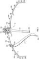
- FIG. 1 provides a left-side perspective view of retractor holding frame 10
- FIGs. 3 and 4 provide center and right-side perspective views of retractor holding frame 10, respectively.
- Retractor holding frame 10 includes a left support frame arm 11 and a right support frame arm 12. Left and right support frame arms 11, 12 are each independently and adjustably supported by support body 13. Support body 13 is, in turn, adjustably supported from a surgical table by an adjustable support arm (not shown).
- support body 13 includes a first bore 14 extending transversely through support body 13 from a first side of support body 13 to a second side of support body 13 opposite the first side.
- Support body 13 also includes a second bore 15 extending transversely through support body 13 from the second side of support body 13 to the first side of support body 13.
- First bore 14 is configured to receive at least a portion of left support frame arm 11 at the first side of support body 13 and second bore 15 is configured to receive at least a portion of right support frame arm 12 at the second side of support body 13.
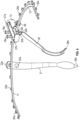
- left support frame arm 11 is provided with an annular hub 16a configured to be disposed in first bore 14 in support body 13.
- right support frame arm 12 in FIG. 6 right support frame arm 12 is provided with an annular hub 16b configured to be disposed in second bore 15 in support body 13.
- each of first and second bores 14, 15 and each of the respective first and second annular hubs 16a, 16b of left and right support frame arms 11, 12 have substantially circular cross-sections so as to allow respective annular hubs 16a, 16b of left and right support frame arms 11, 12 to fit and rotate within respective first and second bores 14, 15 of support body 13.
- each of first and second annular hubs 16a, 16b have respective tapered distal ends 27a, 27b, which allow for easy alignment and insertion of respective first and second annular hubs 16a, 16b into respective first and second bores 14, 15.
- each of first and second annular hubs 16a, 16b further include a respective annular series of recesses or detents 17a', 17b' configured to selectively receive a respective retaining pin 17a, 17b of a respective spring-biased locking mechanism 18a, 18b disposed on a top surface of support body 13.
- respective retaining pins 17a, 17b are configured to extend down into respective first and second bores 14, 15, under force provided by respective spring-biased locking mechanisms 18a, 18b, and seat and/or index within a respective one of the respective annular series of recesses or detents 17a', 17b' of respective hubs 16a, 16b.
- respective portions of spring-biased locking mechanisms 18a, 18b can be pulled upwardly to thereby retract respective retaining pins 17a, 17b sufficiently to allow respective annular hubs 16a, 16b of respective left and right support frame arms 11, 12 to be inserted into respective first and second bores 14, 15 and respective left and right support frame arms 11, 12 to be rotated to respective desired positions.
- Support body 13 is further provided with a quick-connect connector 28 for coupling support body 13 to a positioning arm (not shown) which, in turn, adjustably supports retractor holding frame 10 from a surgical table.
- a positioning arm (not shown) which, in turn, adjustably supports retractor holding frame 10 from a surgical table.
- a number of conventional positioning arms are available on the market.
- left and right support frame arms 11, 12 having any suitable shape.
- left and right support frame arms 11, 12 may have a substantially curved shape as illustrated in FIGs. 1 and 3-6 .
- one or both of left and right support frame arms 11, 12 could also and/or alternatively have a substantially straight shape, or one or more portions may have a substantially curved shape, while one or more other portions may have a substantially curved shape to suit the particular application.
- different sized and/or shaped left and right support frame arms 11, 12 may be readily substituted, inserted and/or removed from support body 13 as described above.
- Left and right support frame arms 11, 12 each further include a respective plurality of retaining hooks or posts 20a, 20b disposed along their outside edges and configured to receive and retain one or more retractors 21 in position.
- one or more retractors 21 may each be provided with a series of apertures 22a at a proximal end 23a and such apertures 22a are configured to receive one of hooks or posts 20a, 20b and thereby retain proximal ends 23a of retractors 21 on those respective hooks or posts 20a, 20b.
- Retractors 21 may have any suitable shape.
- retractors 21 may have at least one curved portion. For example, as illustrated in FIGs.
- proximal 23a and distal 26a ends of retractor 21 can be substantially curved.
- retractors 21 may have at least one substantially straight portion.
- a medial portion of retractor 21 can be substantially straight.
- at least a portion of retractor 21 can be tapered.
- retractor 21 can taper along its length of extension at least from its medial portion to distal end 26a. Such a tapered aspect may allow retractors 21 to more effectively focus retention force to a particular portion of a patient's tissue. It should also be appreciated that, while the figures illustrate one retractor 21 disposed on left support frame arm 11, one or more retractors 21 can also or alternatively be similarly disposed on right support frame 12.
- an underside of support body 13 can further include one or more hooks or posts 24 configured to receive and retain in position one or more additional retractors 25.
- one or more additional retractors 25 can each be provided with a similar series of apertures 22b at a similar proximal end 23b of additional retractors 25, and such apertures 22b of additional retractors 25 are configured to receive one of hooks or posts 24 on underside of support body 13 and thereby retain proximal end(s) 23b of additional retractor(s) 25 on respective hooks or posts 24.
- retractors 25 may have any suitable shape.
- retractors 25 may have at least one curved portion. For example, as illustrated in FIGs.
- proximal 23b and distal 26b ends of retractor 25 can be substantially curved.
- retractors 25 may have at least one substantially straight portion.
- a medial portion of retractor 25 can be substantially straight.
- at least a portion of retractor 25 can be tapered.
- retractor 25 can taper along its length of extension at least from its medial portion to distal end 26b. Such a tapered aspect may allow retractors 25 to more effectively focus retention force to a particular portion of a patient's tissue.
- respective distal ends 26a, 26b of retractors 21, 25 may be adjustably positioned to retain and spread patient tissue at an incision made at a surgical access point on the patient. This allows the surgeon to securely place and hold a set of retractors 21, 25 during a surgical procedure without the need for additional surgical staff.
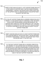
- FIG. 7 illustrates a flowchart 700 corresponding to such a method of use, in accordance with embodiments which do not form part of the invention. While flowchart 700 illustrates one or more actions and/or steps, it should be understood that one or more described actions can be omitted, one or more additional or alternative actions can be added, and/or one or more actions can be performed in another order than that specifically described without departing from the scope of the present disclosure.
- Block 702 includes inserting a first annular hub of a left support frame arm into a first bore of a support body, the first bore extending transversely through the support body from a first side of the support body to a second side of the support body opposite the first side.
- first annular hub 16a of left support frame arm 11 can be inserted into first bore 14 of support body 13.
- First bore 14 extends transversely through support body 13 from a first side of support body 13 to a second side of support body 13 opposite the first side.
- inserting the first annular hub of the left support frame arm into the first bore of the support body includes utilizing at least a portion of first spring-biased locking mechanism 18a to retract first retaining pin 17a sufficiently from first bore 14 to allow annular hub 16a of left support frame arm 11 to be inserted into first bore 14.
- first annular hub 16a has a tapered distal end 27a configured to aid alignment between first annular hub 16a and first bore 14.
- Block 704 includes fixing the left support frame arm in a desired orientation with respect to the support body by disposing a first retaining pin of a first spring-biased locking mechanism of the support body down into the first bore such that the first retaining pin is received into one of a first annular series of detents disposed in the first annular hub of the left support frame arm.
- left support frame arm 11 can be fixed in a desired orientation with respect to support body 13 by disposing first retaining pin 17a of first spring-biased locking mechanism 18a of support body 13 down into first bore 14 such that first retaining pin 17a is received into one of a first annular series of detents 17a' disposed in annular hub 16a of left support frame arm 11.
- fixing the left support frame arm in the desired orientation with respect to the support body includes first rotating left support frame arm 11 to the desired orientation while its annular hub 16a is disposed within first bore 14 and first retaining pin 17a is retracted from first bore 14.
- left support frame arm 11 further comprises first plurality of posts 20a disposed along an outer edge of left support frame arm 11.
- flowchart 700 may further include securing one of a series of apertures 22a, disposed at a proximal end 23a of a first retractor 21, to one of the first plurality of posts 20a of left support frame arm 11 to thereby retain first retractor 21 in a first desired orientation.
- Block 706 includes inserting a second annular hub of a right support frame arm into a second bore of the support body, the second bore extending transversely through the support body from the second side to the first side.
- annular hub 16b of right support frame arm 12 can be inserted into second bore 15 of support body 13.
- Second bore 15 extends transversely through support body 13 from the second side of support body 13 to the first side of support body 13.
- inserting the second annular hub of the right support frame arm into the second bore of the support body includes utilizing at least a portion of second spring-biased locking mechanism 18b to retract second retaining pin 17b sufficiently from second bore 15 to allow annular hub 16b of right support frame arm 12 to be inserted into second bore 15.
- second annular hub 16b has a tapered distal end 27b configured to aid alignment between second annular hub 16b and second bore 15.
- Block 708 includes fixing the right support frame arm in a desired orientation with respect to the support body by disposing a second retaining pin of a second spring-biased locking mechanism of the support body down into the second bore such that the second retaining pin is received into one of a second annular series of detents disposed in the second annular hub of the right support frame arm.
- right support frame arm 12 can be fixed in a desired orientation with respect to support body 13 by disposing second retaining pin 17a of second spring-biased locking mechanism 18b of support body 13 down into second bore 15 such that second retaining pin 17b is received into one of a second annular series of detents 17b' disposed in annular hub 16b of right support frame arm 12.
- fixing the right support frame arm in the desired orientation with respect to the support body includes first rotating right support frame arm 12 to the desired orientation while its annular hub 16b is disposed within second bore 15 and second retaining pin 17b is retracted from second bore 15.
- an underside of support body 13 further comprises at least one post 24 and flowchart 700 can further include securing one of a series of apertures 22b, disposed at a proximal end 23b of an additional retractor 25, to one of the at least one post 24 on the underside of support body 13 to thereby retain additional retractor 25 in an additional desired orientation.
- each of the first and second annular hubs 16a, 16b, first bore 14 and second bore 15 have a circular cross-section, thereby allowing the first annular hub 16ab to rotate within first bore 14 and left support frame arm 11 to rotate with respect to support body 13 and thereby allowing the second annular hub 16b to rotate within second bore 15 and right support frame arm 12 to rotate with respect to support body 13.
- support body 13 further includes quick-connect connector 28 and flowchart 700 can further include coupling support body 13 to a positioning arm utilizing quick-connect connector 28.
- at least one respective portion of each of left and right support frame arms 11,12 has a curved shape.
- at least one respective portion of each of left and right support frame arms 11, 12 has a substantially straight shape.
- at least one of first and second retractors 21 taper along their respective lengths.
- first and second retractors 21 each comprise at least one curved portion.
- FIG. 8 illustrates a flowchart 800 corresponding to such a method of manufacture, in accordance with the invention. While flowchart 800 illustrates one or more actions and/or steps, it should be understood that one or more described actions can be omitted, one or more additional or alternative actions can be added, and/or one or more actions can be performed in another order than that specifically described without departing from the scope of the present disclosure.
- Block 802 includes providing a support body having a first side and a second side opposite the first side.
- a support body having a first side and a second side opposite the first side.
- Block 804 includes forming a first bore extending transversely through the support body from the first side to the second side.
- first bore 14 is formed to extend transversely through support body 13 from a first side of support body 13 to a second side of support body 13 opposite the first side.
- Block 806 includes forming a second bore extending transversely through the support body from the second side to the first side.
- second bore 15 extends transversely through support body 13 from the second side of support body 13 to the first of support body 13.
- Block 808 includes providing a left support frame arm comprising a first annular hub configured to be disposed within the first bore of the support body, and a first plurality of posts disposed along an outer edge of the left support frame arm and configured to receive and retain at least a first retractor in a first desired orientation.
- left support frame arm 11 is provided including annular hub 16a configured to be disposed within first bore 14 of support body 13, and a first plurality of posts 20a disposed along an outer edge of left support frame arm 11 and configured to receive and retain at least a first retractor 21 in a first desired orientation.
- Block 810 includes providing a right support frame arm comprising a second annular hub configured to be disposed within the second bore of the support body, and a second plurality of posts disposed along an outer edge of the right support frame arm and configured to receive and retain at least a second retractor in a second desired orientation.
- right support frame arm 12 is provided including annular hub 16b configured to be disposed within second bore 15 of support body 13, and a second plurality of posts 20b disposed along an outer edge of right support frame arm 12 and configured to receive and retain at least a second retractor 21 in a second desired orientation.
- each of first and second annular hubs 16a, 16b, first bore 14 and second bore 15 are formed to have a circular cross-section, thereby allowing the first annular hub 16a to rotate within first bore 14 and left support frame arm 11 to rotate with respect to support body 13 and thereby allowing the second annular hub 16b to rotate within second bore 15 and right support frame arm 12 to rotate with respect to support body 13.
- flowchart 800 can further include disposing at least one post 24 on an underside of support body 13 such that the at least one post 24 is configured to receive and retain at least one additional retractor 25 in an additional desired orientation.
- flowchart 800 can further include forming a tapered distal end 27a on first annular hub 16a to aid alignment between first annular hub 16a and first bore 14. In some embodiments, flowchart 800 can further include forming a tapered distal end 27b on the second annular hub 16b to aid alignment between second annular hub 16b and second bore 15.
- flowchart 800 further includes providing a first spring-biased locking mechanism 18a, including a first retaining pin 17a configured to extend down into first bore 14, on support body 13.
- providing the first spring-biased locking mechanism includes providing at least a portion of the first spring-biased locking mechanism 18a that is configured to retract the first retaining pin 17a sufficiently from first bore 14 to allow first annular hub 16a to be inserted into first bore 14 or left support frame arm 11 to be rotated with respect to support body 13 while first annular hub 16a is disposed within first bore 14.
- flowchart 800 further includes providing second spring-biased locking mechanism 18b, including second retaining pin 17b configured to extend down into second bore 15, on support body 13.
- providing second spring-biased locking mechanism 18b includes providing at least a portion of second spring-biased locking mechanism 18b that is configured to retract second retaining pin 17b sufficiently from second bore 15 to allow second annular hub 16b to be inserted into second bore 15 or right support frame arm 12 to be rotated with respect to support body 13 while second annular hub 16b is disposed within second bore 15.
- flowchart 800 further includes forming a first annular series of detents 17a' in first annular hub 16a configured to selectively receive first retaining pin 17a and thereby fix left support frame arm 11 in a desired orientation with respect to support body 13.
- Flowchart 800 further includes forming a second annular series of detents 17b' in second annular hub 16b configured to selectively receive second retaining pin 17b and thereby fix right support frame arm 12 in a desired orientation with respect to support body 13.
- flowchart 800 can further include securing quick-connect connector 28 to support body 13, quick-connect connector 28 being configured to couple support body 13 to a positioning arm.
- At least one respective portion of each of left and right support frame arms 11, 12 has a curved shape. In some embodiments, at least one respective portion of each of left and right support frame arms 11, 12 has a substantially straight shape.
- flowchart 800 can further include providing the first retractor 21 having a series of apertures 22a disposed at proximal end 23b thereof, the series of apertures 22a configured to receive a post of first plurality of posts 20b of left support frame arm 11 and thereby retain proximal end 23a of first retractor 21 thereon.
- flowchart 800 can further include providing the second retractor 21 having a series of apertures 22a disposed at a proximal end 23a thereof, the series of apertures 22a configured to receive a post of the second plurality of posts 20b of right support frame arm 12 and thereby retain proximal end 23a of second retractor 21 thereon.
- flowchart 800 can further include providing the additional retractor 25 having a series of apertures 22b disposed at a proximal end 23b thereof, the series of apertures 22b configured to receive the at least one post 24 on the underside of support body 13 and thereby retain proximal end 23b of additional retractor 25 thereon.
- At least one of the first and second retractors 21 tapers along their respective lengths. In some embodiments, the first and second retractors 21 each comprise at least one curved portion.
Landscapes
- Health & Medical Sciences (AREA)
- Life Sciences & Earth Sciences (AREA)
- Surgery (AREA)
- Molecular Biology (AREA)
- Engineering & Computer Science (AREA)
- Biomedical Technology (AREA)
- Heart & Thoracic Surgery (AREA)
- Medical Informatics (AREA)
- Nuclear Medicine, Radiotherapy & Molecular Imaging (AREA)
- Animal Behavior & Ethology (AREA)
- General Health & Medical Sciences (AREA)
- Public Health (AREA)
- Veterinary Medicine (AREA)
- Oral & Maxillofacial Surgery (AREA)
- Pathology (AREA)
- Surgical Instruments (AREA)
Description
- The present invention relates generally to surgical retractors and more particularly, to a retractor frame holding assembly and related manufacturing methods involving the same.
- Open and mini-open surgical procedures require multiple instruments, e.g., for retracting and holding both instruments and the patient's tissue. There are many soft tissue surgical procedures, such as about the shoulder or hip, that require such an open or mini-open technique, as opposed to an arthroscopic technique. These open or mini-open procedures require expensive resources, including but not limited to additional staff surgeons and assistants to hold the various retraction and/or surgical instruments.
- Unfortunately, such additional staff is costly and can provide inconsistent medical support (e.g., holding tissues in one or more retracted positions). Accordingly, there is a need for an effective and efficient retractor holding device to overcome the drawbacks associated with prior art retractor holders and techniques.
- It should be noted that this Background is not intended to be an aid in determining the scope of the claimed subject matter nor be viewed as limiting the claimed subject matter to implementations that solve any or all of the disadvantages or problems presented above. The discussion of any technology, documents, or references in this Background section should not be interpreted as an admission that the material described is prior art to any of the subject matter claimed herein.
-
US-A-2013/082157 describes a retractor ring assembly includes a ring holder that has a first selectively engaged connection and a second selectively engaged connection. A first and second ring portion each has a proximal end and a distal end. The proximal end of the first and second ring portions are selectively connected to the respective first and second selectively engaged connections of the ring holder. The distal end of the first ring portion has a third selectively engaged connection. The distal end of the second ring portion has a fourth selectively engaged connection. The third selectively engaged connection and the fourth selectively engaged connection are connectable to form a reinforced closed ring configuration, and are disconnectable to form an open ring configuration. -
US-A-2005/215865 describes a method of performing surgical retraction of flesh includes positioning a patient on a surgical table and making an incision into the flesh of the patient. A retractor support is mounted to the surgical table and positioned proximate the incision with a blade positioned within the incision and having a flexible member attached to the blade. The retractor blade is positioned manually to retract flesh. The flexible member in tension is attached to the retractor support thereby retracting the flesh and exposing the surgical site. - In embodiments, a retractor holding frame is provided as defined by claim 1.
- In embodiments, a method of manufacturing a retractor holding frame is provided as defined by claim 14.
- It is understood that various configurations of the subject technology will become apparent to those skilled in the art from the disclosure, wherein various configurations of the subject technology are shown and described by way of illustration. As will be realized, the subject technology is capable of other and different configurations and its several details are capable of modification in various other respects, all without departing from the scope of the subject technology. Accordingly, the summary, drawings and detailed description are to be regarded as illustrative in nature and not as restrictive.
- Various embodiments are discussed in detail in conjunction with the Figures described below, with an emphasis on highlighting the advantageous features. These embodiments are for illustrative purposes only and any scale that may be illustrated therein does not limit the scope of the technology disclosed. These drawings include the following figures, in which like numerals indicate like parts.
-
FIG. 1 is a left-side perspective view of a retractor holding frame, according to some embodiments; -
FIG. 2 is an enlarged side elevation view of a support body of the retractor holding frame ofFIG. 1 , according to some embodiments; -
FIG. 3 is a center perspective view of the retractor holding frame ofFIG. 1 , according to some embodiments; -
FIG. 4 is a right-side perspective view of the retractor holding frame ofFIG. 1 , according to some embodiments; -
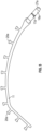
FIG. 5 is a top plan view of a left-side frame arm of the retractor holding frame ofFIG. 1 , according to some embodiments; -
FIG. 6 is a top plan view of a right-side frame arm of the retractor holding frame ofFIG. 1 , according to some embodiments; -
FIG. 7 illustrates a flowchart related to a method of using a retractor holding frame, in accordance with some embodiments; and -
FIG. 8 illustrates a flowchart related to a method of manufacturing a retractor holding frame, in accordance with some embodiments. - The following description and examples illustrate some exemplary implementations, embodiments, and arrangements of the disclosed invention in detail. Those of skill in the art will recognize that there are numerous variations and modifications of this invention that are encompassed by its scope. Accordingly, the description of a certain example embodiment should not be deemed to limit the scope of the present invention.
- Implementations of the technology described herein are directed generally to a retractor holding frame assembly and related methods.
- Various aspects of the novel systems, apparatuses, and methods are described more fully hereinafter with reference to the accompanying drawings. The teachings disclosure may, however, be embodied in many different forms and should not be construed as limited to any specific structure or function presented throughout this disclosure. Rather, these aspects are provided so that this disclosure will be thorough and complete, and will fully convey the scope of the disclosure to those skilled in the art. Based on the teachings herein one skilled in the art should appreciate that the scope of the disclosure is intended to cover any aspect of the novel systems, apparatuses, and methods disclosed herein, whether implemented independently of or combined with any other aspect of the disclosure. For example, a system or an apparatus may be implemented, or a method may be practiced using any one or more of the aspects set forth herein. In addition, the scope of the disclosure is intended to cover such a system, apparatus or method which is practiced using other structure, functionality, or structure and functionality in addition to or other than the various aspects of the disclosure set forth herein. It should be understood that any aspect disclosed herein may be set forth in one or more elements of a claim. Although some benefits and advantages of the preferred aspects are mentioned, the scope of the disclosure is not intended to be limited to particular benefits, uses, or objectives. The detailed description and drawings are merely illustrative of the disclosure rather than limiting, the scope of the disclosure being defined by the appended claims.
- With respect to the use of plural vs. singular terms herein, those having skill in the art can translate from the plural to the singular and/or from the singular to the plural as is appropriate to the context and/or application. The various singular/plural permutations may be expressly set forth herein for sake of clarity.
- When describing an absolute value of a characteristic or property of a thing or act described herein, the terms "substantial," "substantially," "essentially," "approximately," and/or other terms or phrases of degree may be used without the specific recitation of a numerical range. When applied to a characteristic or property of a thing or act described herein, these terms refer to a range of the characteristic or property that is consistent with providing a desired function associated with that characteristic or property.
- In those cases where a single numerical value is given for a characteristic or property, it is intended to be interpreted as at least covering deviations of that value within one significant digit of the numerical value given.
- If a numerical value or range of numerical values is provided to define a characteristic or property of a thing or act described herein, whether or not the value or range is qualified with a term of degree, a specific method of measuring the characteristic or property may be defined herein as well. In the event no specific method of measuring the characteristic or property is defined herein, and there are different generally accepted methods of measurement for the characteristic or property, then the measurement method should be interpreted as the method of measurement that would most likely be adopted by one of ordinary skill in the art given the description and context of the characteristic or property. In the further event there is more than one method of measurement that is equally likely to be adopted by one of ordinary skill in the art to measure the characteristic or property, the value or range of values should be interpreted as being met regardless of which method of measurement is chosen.
- It will be understood by those within the art that terms used herein, and especially in the appended claims (e.g., bodies of the appended claims) are intended as "open" terms unless specifically indicated otherwise (e.g., the term "including" should be interpreted as "including but not limited to," the term "having" should be interpreted as "having at least," the term "includes" should be interpreted as "includes but is not limited to," etc.).
- It will be further understood by those within the art that if a specific number of an introduced claim recitation is intended, such an intent will be explicitly recited in the claim, and in the absence of such recitation no such intent is present. For example, as an aid to understanding, the following appended claims may contain usage of the introductory phrases "at least one" and "one or more" to introduce claim recitations. However, the use of such phrases should not be construed to imply that the introduction of a claim recitation by the indefinite articles "a" or "an" limits any particular claim containing such introduced claim recitation to embodiments containing only one such recitation, even when the same claim includes the introductory phrases "one or more" or "at least one" and indefinite articles such as "a" or "an" (e.g., "a" and/or "an" should typically be interpreted to mean "at least one" or "one or more"); the same holds true for the use of definite articles used to introduce claim recitations. In addition, even if a specific number of an introduced claim recitation is explicitly recited, those skilled in the art will recognize that such recitation should typically be interpreted to mean at least the recited number (e.g., the bare recitation of "two recitations," without other modifiers, typically means at least two recitations, or two or more recitations).
- In those instances where a convention analogous to "at least one of A, B, and C" is used, such a construction would include systems that have A alone, B alone, C alone, A and B together without C, A and C together without B, B and C together without A, as well as A, B, and C together. It will be further understood by those within the art that virtually any disjunctive word and/or phrase presenting two or more alternative terms, whether in the description, claims, or drawings, should be understood to contemplate the possibilities of including one of the terms, either of the terms, or both terms. For example, the phrase "A or B" will be understood to include A without B, B without A, as well as A and B together."
- Various modifications to the implementations described in this disclosure can be readily apparent to those skilled in the art, and generic principles defined herein can be applied to other implementations without departing from the scope of this disclosure. Thus, the disclosure is not intended to be limited to the implementations shown herein but is to be accorded the widest scope consistent with the claims, the principles and the novel features disclosed herein. The word "exemplary" is used exclusively herein to mean "serving as an example, instance, or illustration." Any implementation described herein as "exemplary" is not necessarily to be construed as preferred or advantageous over other implementations.
- Certain features that are described in this specification in the context of separate implementations also can be implemented in combination in a single implementation. Conversely, various features that are described in the context of a single implementation also can be implemented in multiple implementations separately or in any suitable sub-combination. Moreover, although features can be described above as acting in certain combinations and even initially claimed as such, one or more features from a claimed combination can in some cases be excised from the combination, and the claimed combination can be directed to a sub-combination or variation of a sub-combination.
- Any methods disclosed herein comprise one or more steps or actions for achieving the described method. The method steps and/or actions may be interchanged with one another without departing from the scope of the claims. In other words, unless a specific order of steps or actions is specified, the order and/or use of specific steps and/or actions may be modified without departing from the scope of the claims.
- The present disclosure describes a
retractor holding frame 10 attached or attachable to the side of a surgical table with an adjustable support arm. Several embodiments ofretractor holding frame 10 will now be discussed in connection withFIGs. 1-8 .FIG. 1 provides a left-side perspective view ofretractor holding frame 10, whileFIGs. 3 and4 provide center and right-side perspective views ofretractor holding frame 10, respectively. -
Retractor holding frame 10 includes a leftsupport frame arm 11 and a rightsupport frame arm 12. Left and rightsupport frame arms support body 13.Support body 13 is, in turn, adjustably supported from a surgical table by an adjustable support arm (not shown). - As best illustrated in the enlarged side elevation view of
support body 13 ofFIG. 2 ,support body 13 includes a first bore 14 extending transversely throughsupport body 13 from a first side ofsupport body 13 to a second side ofsupport body 13 opposite the first side.Support body 13 also includes asecond bore 15 extending transversely throughsupport body 13 from the second side ofsupport body 13 to the first side ofsupport body 13. First bore 14 is configured to receive at least a portion of leftsupport frame arm 11 at the first side ofsupport body 13 and second bore 15 is configured to receive at least a portion of rightsupport frame arm 12 at the second side ofsupport body 13. - As best illustrated by the top plan view of left
support frame arm 11 inFIG. 5 , leftsupport frame arm 11 is provided with anannular hub 16a configured to be disposed in first bore 14 insupport body 13. Similarly, as best illustrated by the top plan view of rightsupport frame arm 12 inFIG. 6 , rightsupport frame arm 12 is provided with anannular hub 16b configured to be disposed insecond bore 15 insupport body 13. In some embodiments, each of first andsecond bores 14, 15 and each of the respective first and secondannular hubs support frame arms annular hubs support frame arms second bores 14, 15 ofsupport body 13. - In some embodiments each of first and second
annular hubs distal ends annular hubs second bores 14, 15. - In embodiments according to the invention, each of first and second
annular hubs detents 17a', 17b' configured to selectively receive arespective retaining pin locking mechanism support body 13. As viewed inFIG. 2 ,respective retaining pins second bores 14, 15, under force provided by respective spring-biasedlocking mechanisms detents 17a', 17b' ofrespective hubs - In operation, respective portions of spring-biased
locking mechanisms respective retaining pins annular hubs support frame arms second bores 14, 15 and respective left and rightsupport frame arms support frame arms locking mechanisms respective retaining pins second bores 14, 15 and seat and/or index within respective ones of the respective annular series of recesses ordetents 17a', 17b' ofrespective hubs frame arms least support body 13. -
Support body 13 is further provided with a quick-connect connector 28 forcoupling support body 13 to a positioning arm (not shown) which, in turn, adjustably supportsretractor holding frame 10 from a surgical table. A number of conventional positioning arms are available on the market. - The present disclosure contemplates each of left and right
support frame arms support frame arms FIGs. 1 and3-6 . However, one or both of left and rightsupport frame arms support frame arms support body 13 as described above. - Left and right
support frame arms posts more retractors 21 in position. For example, one ormore retractors 21 may each be provided with a series ofapertures 22a at aproximal end 23a andsuch apertures 22a are configured to receive one of hooks orposts proximal ends 23a ofretractors 21 on those respective hooks orposts Retractors 21 may have any suitable shape. For example,retractors 21 may have at least one curved portion. For example, as illustrated inFIGs. 1 ,3 and4 , proximal 23a and distal 26a ends ofretractor 21 can be substantially curved. In some embodiments,retractors 21 may have at least one substantially straight portion. For example, as illustrated inFIGs. 1 ,3 and4 , a medial portion ofretractor 21 can be substantially straight. In some embodiments, at least a portion ofretractor 21 can be tapered. For example, as illustrated inFIGs. 1 ,3 and4 , in some embodiments,retractor 21 can taper along its length of extension at least from its medial portion todistal end 26a. Such a tapered aspect may allowretractors 21 to more effectively focus retention force to a particular portion of a patient's tissue. It should also be appreciated that, while the figures illustrate oneretractor 21 disposed on leftsupport frame arm 11, one ormore retractors 21 can also or alternatively be similarly disposed onright support frame 12. - In some embodiments, an underside of
support body 13 can further include one or more hooks orposts 24 configured to receive and retain in position one or moreadditional retractors 25. For example, one or moreadditional retractors 25 can each be provided with a similar series ofapertures 22b at a similarproximal end 23b ofadditional retractors 25, andsuch apertures 22b ofadditional retractors 25 are configured to receive one of hooks orposts 24 on underside ofsupport body 13 and thereby retain proximal end(s) 23b of additional retractor(s) 25 on respective hooks or posts 24. As described above in connection with retractor(s) 21,retractors 25 may have any suitable shape. For example,retractors 25 may have at least one curved portion. For example, as illustrated inFIGs. 1 ,3 and4 , proximal 23b and distal 26b ends ofretractor 25 can be substantially curved. In some embodiments,retractors 25 may have at least one substantially straight portion. For example, as illustrated inFIGs. 1 ,3 and4 , a medial portion ofretractor 25 can be substantially straight. In some embodiments, at least a portion ofretractor 25 can be tapered. For example, as illustrated inFIGs. 1 ,3 and4 , in some embodiments,retractor 25 can taper along its length of extension at least from its medial portion todistal end 26b. Such a tapered aspect may allowretractors 25 to more effectively focus retention force to a particular portion of a patient's tissue. - In the manner described above, respective
distal ends retractors retractors - Discussion now turns to an example method of using a retractor holding frame, for example, as that described in connection with any of
FIGs. 1-6 .FIG. 7 illustrates aflowchart 700 corresponding to such a method of use, in accordance with embodiments which do not form part of the invention. Whileflowchart 700 illustrates one or more actions and/or steps, it should be understood that one or more described actions can be omitted, one or more additional or alternative actions can be added, and/or one or more actions can be performed in another order than that specifically described without departing from the scope of the present disclosure. -
Block 702 includes inserting a first annular hub of a left support frame arm into a first bore of a support body, the first bore extending transversely through the support body from a first side of the support body to a second side of the support body opposite the first side. For example, as previously described in connection with at least one figure, firstannular hub 16a of leftsupport frame arm 11 can be inserted into first bore 14 ofsupport body 13. First bore 14 extends transversely throughsupport body 13 from a first side ofsupport body 13 to a second side ofsupport body 13 opposite the first side. - In some embodiments, inserting the first annular hub of the left support frame arm into the first bore of the support body includes utilizing at least a portion of first spring-biased
locking mechanism 18a to retractfirst retaining pin 17a sufficiently from first bore 14 to allowannular hub 16a of leftsupport frame arm 11 to be inserted into first bore 14. In some embodiments, firstannular hub 16a has a tapereddistal end 27a configured to aid alignment between firstannular hub 16a and first bore 14. -
Block 704 includes fixing the left support frame arm in a desired orientation with respect to the support body by disposing a first retaining pin of a first spring-biased locking mechanism of the support body down into the first bore such that the first retaining pin is received into one of a first annular series of detents disposed in the first annular hub of the left support frame arm. For example, as previously described in connection with at least one figure, leftsupport frame arm 11 can be fixed in a desired orientation with respect to supportbody 13 by disposingfirst retaining pin 17a of first spring-biasedlocking mechanism 18a ofsupport body 13 down into first bore 14 such that first retainingpin 17a is received into one of a first annular series ofdetents 17a' disposed inannular hub 16a of leftsupport frame arm 11. - In some embodiments, fixing the left support frame arm in the desired orientation with respect to the support body includes first rotating left
support frame arm 11 to the desired orientation while itsannular hub 16a is disposed within first bore 14 and first retainingpin 17a is retracted from first bore 14. - In some embodiments, left
support frame arm 11 further comprises first plurality ofposts 20a disposed along an outer edge of leftsupport frame arm 11. In some such embodiments,flowchart 700 may further include securing one of a series ofapertures 22a, disposed at aproximal end 23a of afirst retractor 21, to one of the first plurality ofposts 20a of leftsupport frame arm 11 to thereby retainfirst retractor 21 in a first desired orientation. -
Block 706 includes inserting a second annular hub of a right support frame arm into a second bore of the support body, the second bore extending transversely through the support body from the second side to the first side. For example, as previously described in connection with at least one figure,annular hub 16b of rightsupport frame arm 12 can be inserted intosecond bore 15 ofsupport body 13. Second bore 15 extends transversely throughsupport body 13 from the second side ofsupport body 13 to the first side ofsupport body 13. - In some embodiments, inserting the second annular hub of the right support frame arm into the second bore of the support body includes utilizing at least a portion of second spring-biased
locking mechanism 18b to retractsecond retaining pin 17b sufficiently fromsecond bore 15 to allowannular hub 16b of rightsupport frame arm 12 to be inserted intosecond bore 15. - In some embodiments, second
annular hub 16b has a tapereddistal end 27b configured to aid alignment between secondannular hub 16b andsecond bore 15. -
Block 708 includes fixing the right support frame arm in a desired orientation with respect to the support body by disposing a second retaining pin of a second spring-biased locking mechanism of the support body down into the second bore such that the second retaining pin is received into one of a second annular series of detents disposed in the second annular hub of the right support frame arm. For example, as previously described in connection with at least one figure, rightsupport frame arm 12 can be fixed in a desired orientation with respect to supportbody 13 by disposingsecond retaining pin 17a of second spring-biasedlocking mechanism 18b ofsupport body 13 down intosecond bore 15 such thatsecond retaining pin 17b is received into one of a second annular series ofdetents 17b' disposed inannular hub 16b of rightsupport frame arm 12. - In some embodiments, fixing the right support frame arm in the desired orientation with respect to the support body includes first rotating right
support frame arm 12 to the desired orientation while itsannular hub 16b is disposed withinsecond bore 15 andsecond retaining pin 17b is retracted fromsecond bore 15. - In some embodiments, an underside of
support body 13 further comprises at least onepost 24 andflowchart 700 can further include securing one of a series ofapertures 22b, disposed at aproximal end 23b of anadditional retractor 25, to one of the at least onepost 24 on the underside ofsupport body 13 to thereby retainadditional retractor 25 in an additional desired orientation. - In some embodiments, each of the first and second
annular hubs support frame arm 11 to rotate with respect to supportbody 13 and thereby allowing the secondannular hub 16b to rotate withinsecond bore 15 and rightsupport frame arm 12 to rotate with respect to supportbody 13. - In some embodiments,
support body 13 further includes quick-connect connector 28 andflowchart 700 can further includecoupling support body 13 to a positioning arm utilizing quick-connect connector 28. In some embodiments, at least one respective portion of each of left and rightsupport frame arms support frame arms second retractors 21 taper along their respective lengths. In some embodiments, first andsecond retractors 21 each comprise at least one curved portion. - Discussion now turns to an example method of manufacturing a retractor holding frame, for example, as that described in connection with any of
FIGs. 1-7 .FIG. 8 illustrates aflowchart 800 corresponding to such a method of manufacture, in accordance with the invention. Whileflowchart 800 illustrates one or more actions and/or steps, it should be understood that one or more described actions can be omitted, one or more additional or alternative actions can be added, and/or one or more actions can be performed in another order than that specifically described without departing from the scope of the present disclosure. -
Block 802 includes providing a support body having a first side and a second side opposite the first side. For example, as previously described in connection with at least one figure,support body 13, having a first side and a second side opposite the first side, is provided. -
Block 804 includes forming a first bore extending transversely through the support body from the first side to the second side. For example, as previously described in connection with at least one figure, first bore 14 is formed to extend transversely throughsupport body 13 from a first side ofsupport body 13 to a second side ofsupport body 13 opposite the first side. -
Block 806 includes forming a second bore extending transversely through the support body from the second side to the first side. For example, as previously described in connection with at least one figure, second bore 15 extends transversely throughsupport body 13 from the second side ofsupport body 13 to the first ofsupport body 13. -
Block 808 includes providing a left support frame arm comprising a first annular hub configured to be disposed within the first bore of the support body, and a first plurality of posts disposed along an outer edge of the left support frame arm and configured to receive and retain at least a first retractor in a first desired orientation. For example, as previously described in connection with at least one figure, leftsupport frame arm 11 is provided includingannular hub 16a configured to be disposed within first bore 14 ofsupport body 13, and a first plurality ofposts 20a disposed along an outer edge of leftsupport frame arm 11 and configured to receive and retain at least afirst retractor 21 in a first desired orientation. -
Block 810 includes providing a right support frame arm comprising a second annular hub configured to be disposed within the second bore of the support body, and a second plurality of posts disposed along an outer edge of the right support frame arm and configured to receive and retain at least a second retractor in a second desired orientation. For example, as previously described in connection with at least one figure, rightsupport frame arm 12 is provided includingannular hub 16b configured to be disposed withinsecond bore 15 ofsupport body 13, and a second plurality ofposts 20b disposed along an outer edge of rightsupport frame arm 12 and configured to receive and retain at least asecond retractor 21 in a second desired orientation. - In some embodiments, each of first and second
annular hubs annular hub 16a to rotate within first bore 14 and leftsupport frame arm 11 to rotate with respect to supportbody 13 and thereby allowing the secondannular hub 16b to rotate withinsecond bore 15 and rightsupport frame arm 12 to rotate with respect to supportbody 13. - In some embodiments,
flowchart 800 can further include disposing at least onepost 24 on an underside ofsupport body 13 such that the at least onepost 24 is configured to receive and retain at least oneadditional retractor 25 in an additional desired orientation. - In some embodiments,
flowchart 800 can further include forming a tapereddistal end 27a on firstannular hub 16a to aid alignment between firstannular hub 16a and first bore 14. In some embodiments,flowchart 800 can further include forming a tapereddistal end 27b on the secondannular hub 16b to aid alignment between secondannular hub 16b andsecond bore 15. - In embodiments according to the invention,
flowchart 800 further includes providing a first spring-biasedlocking mechanism 18a, including afirst retaining pin 17a configured to extend down into first bore 14, onsupport body 13. In such embodiments, providing the first spring-biased locking mechanism includes providing at least a portion of the first spring-biasedlocking mechanism 18a that is configured to retract thefirst retaining pin 17a sufficiently from first bore 14 to allow firstannular hub 16a to be inserted into first bore 14 or leftsupport frame arm 11 to be rotated with respect to supportbody 13 while firstannular hub 16a is disposed within first bore 14. - In embodiments according to the invention,
flowchart 800 further includes providing second spring-biasedlocking mechanism 18b, includingsecond retaining pin 17b configured to extend down intosecond bore 15, onsupport body 13. In such embodiments, providing second spring-biasedlocking mechanism 18b includes providing at least a portion of second spring-biasedlocking mechanism 18b that is configured to retractsecond retaining pin 17b sufficiently fromsecond bore 15 to allow secondannular hub 16b to be inserted intosecond bore 15 or rightsupport frame arm 12 to be rotated with respect to supportbody 13 while secondannular hub 16b is disposed withinsecond bore 15. - In embodiments according to the invention,
flowchart 800 further includes forming a first annular series ofdetents 17a' in firstannular hub 16a configured to selectively receivefirst retaining pin 17a and thereby fix leftsupport frame arm 11 in a desired orientation with respect to supportbody 13.Flowchart 800 further includes forming a second annular series ofdetents 17b' in secondannular hub 16b configured to selectively receivesecond retaining pin 17b and thereby fix rightsupport frame arm 12 in a desired orientation with respect to supportbody 13. - In some embodiments,
flowchart 800 can further include securing quick-connect connector 28 to supportbody 13, quick-connect connector 28 being configured to couplesupport body 13 to a positioning arm. - In some embodiments, at least one respective portion of each of left and right
support frame arms support frame arms - In some embodiments,
flowchart 800 can further include providing thefirst retractor 21 having a series ofapertures 22a disposed atproximal end 23b thereof, the series ofapertures 22a configured to receive a post of first plurality ofposts 20b of leftsupport frame arm 11 and thereby retainproximal end 23a offirst retractor 21 thereon. - In some embodiments,
flowchart 800 can further include providing thesecond retractor 21 having a series ofapertures 22a disposed at aproximal end 23a thereof, the series ofapertures 22a configured to receive a post of the second plurality ofposts 20b of rightsupport frame arm 12 and thereby retainproximal end 23a ofsecond retractor 21 thereon. - In some embodiments,
flowchart 800 can further include providing theadditional retractor 25 having a series ofapertures 22b disposed at aproximal end 23b thereof, the series ofapertures 22b configured to receive the at least onepost 24 on the underside ofsupport body 13 and thereby retainproximal end 23b ofadditional retractor 25 thereon. - In some embodiments, at least one of the first and
second retractors 21 tapers along their respective lengths. In some embodiments, the first andsecond retractors 21 each comprise at least one curved portion. - Reference throughout this disclosure to "an embodiment" or "the embodiment" means that a particular feature, structure or characteristic described in connection with that embodiment is included in at least one embodiment. Thus, the quoted phrases, or variations thereof, as recited throughout this disclosure are not necessarily all referring to the same embodiment.
- Similarly, it should be appreciated that in the above description of embodiments, various features are sometimes grouped together in a single embodiment, Figure, or description thereof for the purpose of streamlining the disclosure. This method of disclosure, however, is not to be interpreted as reflecting an intention that any claim in this or any application claiming priority to this application require more features than those expressly recited in that claim. Rather, as the following claims reflect, inventive aspects lie in a combination of fewer than all features of any single foregoing disclosed embodiment. Thus, the claims following this Detailed Description are hereby expressly incorporated into this Detailed Description, with each claim standing on its own as a separate embodiment. This disclosure includes all permutations of the independent claims with their dependent claims.
- Recitation in the claims of the term "first" with respect to a feature or element does not necessarily imply the existence of a second or additional such feature or element.
- While specific embodiments and applications of the present disclosure have been illustrated and described, it is to be understood that the disclosure is not limited to the precise configuration and components disclosed herein. Various modifications, changes, and variations which will be apparent to those skilled in the art may be made in the arrangement, operation, and details of the methods and systems of the present disclosure disclosed herein without departing from the scope of the disclosure.
Claims (15)
- A retractor holding frame (10), comprising:a support body (13) comprising:a first bore (14) extending transversely through the support body from a first side of the support body to a second side of the support body opposite the first side,a second bore (15) extending transversely through the support body from the second side to the first side,a left support frame arm (11) comprising:a first annular hub (16a) configured to be disposed within the first bore of the support body,a first plurality of posts (20a) disposed along an outer edge of the left support frame arm and configured to receive and retain at least a first retractor (21) in a first orientation, anda right support frame arm (12) comprising:the support body further comprises:a second annular hub (16b) configured to be disposed within the second bore of the support body,a second plurality of posts (20b) disposed along an outer edge of the right support frame arm and configured to receive and retain at least a second retractor (21) in a second orientation,characterised in thata first spring-biased locking mechanism (18a) including a first retaining pin (17a) configured to extend down into the first bore, anda second spring-biased locking mechanism (18b) including a second retaining pin (17b) configured to extend down into the second bore;the left support frame arm comprises a first annular series of detents (17a') configured to selectively receive the first retaining pin and thereby fix the left support frame in a desired orientation with respect to the support body; andthe right support frame arm comprises a second annular series of detents (17b')configured to selectively receive the second retaining pin and thereby fix the rightsupport frame in a desired orientation with respect to the support body.
- The retractor holding frame of claim 1, wherein an underside of the support body further comprises at least one post (24) configured to receive and retain at least one additional retractor (25) in a third orientation.
- The retractor of claim 1, wherein each of the first annular hub, the second annular hub, the first bore and the second bore have a circular cross-section, thereby allowing the first annular hub to rotate within the first bore and the left support frame arm to rotate with respect to the support body and thereby allowing the second annular hub to rotate within the second bore and the right support frame arm to rotate with respect to the support body.
- The retractor holding frame of claim 1, wherein:the first annular hub has a tapered distal end (27a) configured to aid alignment between the first annular hub and the first bore; andthe second annular hub has a tapered distal end (27b) configured to aid alignment between the second annular hub and the second bore.
- The retractor holding frame of claim 1, wherein:at least a portion of the first spring-biased locking mechanism is configured to retract the first retaining pin sufficiently from the first bore to allow the first annular hub to be inserted into the first bore or the left support frame arm to be rotated with respect to the support body while the first annular hub is disposed within the first bore; andat least a portion of the second spring-biased locking mechanism is configured to retract the second retaining pin sufficiently from the second bore to allow the second annular hub to be inserted into the second bore or the right support frame arm to be rotated with respect to the support body while the second annular hub is disposed within the second bore.
- The retractor holding frame of claim 1, wherein the support body further comprises a quick-connect connector (28) configured to couple the support body to a positioning arm.
- The retractor holding frame of claim 1, wherein at least one respective portion of each of the left and right support frame arms has a curved shape.
- The retractor holding frame of claim 1, wherein at least one respective portion of each of the left and right support frame arms has a substantially straight shape.
- The retractor holding frame of claim 1, further comprising the first retractor, wherein the first retractor comprises a first series of apertures (22a) disposed at a proximal end (23a) of the first retractor and configured to receive a post of the first plurality of posts of the left support frame arm and thereby retain the proximal end of the first retractor thereon.
- The retractor holding frame of claim 9, further comprising a second retractor (21), wherein the second retractor comprises a second series of apertures (22a) disposed at a proximal end (23a) of the second retractor and configured to receive a post of the second plurality of posts of the right support frame arm and thereby retain the proximal end of the second retractor thereon.
- The retractor holding frame of claim 2, further comprising the additional retractor, wherein the additional retractor comprises an additional series of apertures (22b) disposed at a proximal end (23b) of the additional retractor and configured to receive the at least one post on the underside of the support body and thereby retain the proximal end of the additional retractor thereon.
- The retractor holding frame of claim 10, wherein at least one of the first and second retractors tapers along their respective lengths.
- The retractor holding frame of claim 10, wherein the first and second retractors each comprise at least one curved portion.
- A method of manufacturing a retractor holding frame (10), the method comprising:providing a support body (13) comprising a first side and a second side opposite the first side;forming a first bore (14) extending transversely through the support body from the first side to the second side;forming a second bore (15) extending transversely through the support body from the second side to the first side;providing a left support frame arm (11) comprising:a first annular hub (16a) configured to be disposed within the first bore of the support body, anda first plurality of posts (20a) disposed along an outer edge of the left support frame arm and configured to receive and retain at least a first retractor (21) in a first orientation;providing a right support frame arm (12) comprising:a second annular hub (16b) configured to be disposed within the second bore of the support body, anda second plurality of posts (20b) disposed along an outer edge of the right support frame arm and configured to receive and retain at least a second retractor (21) in a second orientation; characterised in that the method further comprises:providing a first spring-biased locking mechanism (18a), including a first retaining pin (17a) configured to extend down into the first bore, on the support body;providing a second spring-biased locking mechanism (18b), including a second retaining pin (17b) configured to extend down into the second bore, on the support body;forming a first annular series of detents (17a') in the first annular hub configured to selectively receive the first retaining pin and thereby fix the left support frame arm in a desired orientation with respect to the support body; andforming a second annular series of detents (17b') in the second annular hub configured to selectively receive the second retaining pin and thereby fix the right support frame arm in a desired orientation with respect to the support body.
- The method of claim 14, further comprising disposing at least one post (24) on an underside of the support body such that the at least one post is configured to receive and retain at least one additional retractor (25) in a third orientation.
Priority Applications (1)
| Application Number | Priority Date | Filing Date | Title |
|---|---|---|---|
| EP24211542.6A EP4559408A3 (en) | 2020-03-03 | 2021-03-02 | Surgical tissue retractor holding frame |
Applications Claiming Priority (2)
| Application Number | Priority Date | Filing Date | Title |
|---|---|---|---|
| US202062984363P | 2020-03-03 | 2020-03-03 | |
| PCT/US2021/020400 WO2021178365A1 (en) | 2020-03-03 | 2021-03-02 | Surgical tissue retractor holding frame |
Related Child Applications (2)
| Application Number | Title | Priority Date | Filing Date |
|---|---|---|---|
| EP24211542.6A Division EP4559408A3 (en) | 2020-03-03 | 2021-03-02 | Surgical tissue retractor holding frame |
| EP24211542.6A Division-Into EP4559408A3 (en) | 2020-03-03 | 2021-03-02 | Surgical tissue retractor holding frame |
Publications (2)
| Publication Number | Publication Date |
|---|---|
| EP4114277A1 EP4114277A1 (en) | 2023-01-11 |
| EP4114277B1 true EP4114277B1 (en) | 2024-12-25 |
Family
ID=75267583
Family Applications (2)
| Application Number | Title | Priority Date | Filing Date |
|---|---|---|---|
| EP21715010.1A Active EP4114277B1 (en) | 2020-03-03 | 2021-03-02 | Surgical tissue retractor holding frame |
| EP24211542.6A Pending EP4559408A3 (en) | 2020-03-03 | 2021-03-02 | Surgical tissue retractor holding frame |
Family Applications After (1)
| Application Number | Title | Priority Date | Filing Date |
|---|---|---|---|
| EP24211542.6A Pending EP4559408A3 (en) | 2020-03-03 | 2021-03-02 | Surgical tissue retractor holding frame |
Country Status (7)
| Country | Link |
|---|---|
| US (2) | US11395646B2 (en) |
| EP (2) | EP4114277B1 (en) |
| JP (1) | JP7466668B2 (en) |
| KR (1) | KR102913166B1 (en) |
| AU (1) | AU2021229480B2 (en) |
| ES (1) | ES3014369T3 (en) |
| WO (1) | WO2021178365A1 (en) |
Families Citing this family (2)
| Publication number | Priority date | Publication date | Assignee | Title |
|---|---|---|---|---|
| EP4114277B1 (en) * | 2020-03-03 | 2024-12-25 | Encore Medical, L.P. dba DJO Surgical | Surgical tissue retractor holding frame |
| US20250248701A1 (en) * | 2022-04-10 | 2025-08-07 | Dessinrx Healthcare Pvt. Ltd | Skin flap retraction device |
Family Cites Families (19)
| Publication number | Priority date | Publication date | Assignee | Title |
|---|---|---|---|---|
| US3509873A (en) * | 1967-04-24 | 1970-05-05 | Jack B Karlin | Retractor |
| US4949707A (en) * | 1984-11-08 | 1990-08-21 | Minnesota Scientific, Inc. | Retractor apparatus |
| US5897087A (en) * | 1994-03-15 | 1999-04-27 | Thompson Surgical Instruments, Inc. | CAM tightened universal joint clamp |
| US5899627A (en) * | 1996-09-12 | 1999-05-04 | Minnesota Scientific, Inc. | Clamp for retractor support |
| US6663563B1 (en) * | 1998-10-02 | 2003-12-16 | Minnesota Scientific, Inc. | Fastening system for retractor support |
| US6659945B2 (en) * | 2001-06-29 | 2003-12-09 | Depuy Orthopaedics, Inc. | Self retaining retractor ring |
| US6790177B2 (en) * | 2002-06-27 | 2004-09-14 | Boss Instruments, Ltd. | Surgical retractor apparatus |
| US20050215865A1 (en) | 2002-07-18 | 2005-09-29 | Minnesota Scientific, Inc. | Method and apparatus for surgical retraction |
| WO2004014213A2 (en) * | 2002-07-18 | 2004-02-19 | Minnesota Scientific, Inc. | Method and apparatus for replacing a knee-joint |
| US7125379B2 (en) * | 2003-09-19 | 2006-10-24 | Minnesota Scientific, Inc. | Surgical support arm docking apparatus |
| AU2007224199B2 (en) * | 2006-03-01 | 2013-09-12 | Boss Instruments, Ltd. | Surgical retractor frame system |
| WO2008055324A2 (en) * | 2006-11-07 | 2008-05-15 | Stanislav Nestorov | Clamping device and retractor system using the same |
| US8894029B2 (en) * | 2011-09-30 | 2014-11-25 | Specialty Surgical Instrumentation, Inc. | Retractor ring holder |
| JP2014533136A (en) * | 2011-10-05 | 2014-12-11 | マーク・エイ・ドッドソン | Module retractor and related methods |
| US9078635B2 (en) * | 2012-02-02 | 2015-07-14 | Tedan Surgical Innovations, Llc | Anterior hip replacement retractor assembly |
| US10786328B2 (en) * | 2016-10-26 | 2020-09-29 | Thompson Surgical Instruments, Inc. | Adaptor handle for surgical retractor |
| US10772704B2 (en) * | 2018-03-12 | 2020-09-15 | Zimmer Biomet CMF and Thoracic, LLC | End effector coupler for surgical arm |
| WO2020061073A1 (en) * | 2018-09-17 | 2020-03-26 | Cestero Ramon Francisco | Adjustable locking surgical retractor |
| EP4114277B1 (en) * | 2020-03-03 | 2024-12-25 | Encore Medical, L.P. dba DJO Surgical | Surgical tissue retractor holding frame |
-
2021
- 2021-03-02 EP EP21715010.1A patent/EP4114277B1/en active Active
- 2021-03-02 JP JP2022549102A patent/JP7466668B2/en active Active
- 2021-03-02 KR KR1020227030079A patent/KR102913166B1/en active Active
- 2021-03-02 ES ES21715010T patent/ES3014369T3/en active Active
- 2021-03-02 WO PCT/US2021/020400 patent/WO2021178365A1/en not_active Ceased
- 2021-03-02 AU AU2021229480A patent/AU2021229480B2/en active Active
- 2021-03-02 EP EP24211542.6A patent/EP4559408A3/en active Pending
- 2021-03-02 US US17/189,549 patent/US11395646B2/en active Active
-
2022
- 2022-07-22 US US17/871,062 patent/US12226089B2/en active Active
Also Published As
| Publication number | Publication date |
|---|---|
| ES3014369T3 (en) | 2025-04-22 |
| JP2023516563A (en) | 2023-04-20 |
| WO2021178365A1 (en) | 2021-09-10 |
| KR102913166B1 (en) | 2026-01-15 |
| JP7466668B2 (en) | 2024-04-12 |
| EP4559408A3 (en) | 2025-07-23 |
| EP4114277A1 (en) | 2023-01-11 |
| US20210275159A1 (en) | 2021-09-09 |
| AU2021229480A1 (en) | 2022-09-22 |
| AU2021229480B2 (en) | 2023-11-23 |
| US11395646B2 (en) | 2022-07-26 |
| KR20220134620A (en) | 2022-10-05 |
| US12226089B2 (en) | 2025-02-18 |
| EP4559408A2 (en) | 2025-05-28 |
| US20230000479A1 (en) | 2023-01-05 |
Similar Documents
| Publication | Publication Date | Title |
|---|---|---|
| JP4717828B2 (en) | Surgical retractor, illuminated cannula, and usage | |
| EP4114277B1 (en) | Surgical tissue retractor holding frame | |
| US6511423B2 (en) | Cross bar for a surgical retractor system | |
| EP1534153B1 (en) | Guide for a medical device | |
| JP4248631B2 (en) | Surgical instrument support device | |
| CN102160808B (en) | Extendible thoracic access port | |
| WO2000015132A3 (en) | Apparatus for frameless stereotactic surgery | |
| EP1269922A1 (en) | Articulated and lockable suture retaining retractor ring | |
| US20090018401A1 (en) | Surgical retractor positioning device | |
| US20120123455A1 (en) | Sutureless vascular anastomosis connection | |
| CN104720882A (en) | Rod insertion device | |
| US20120053573A1 (en) | Surgical Apparatus | |
| TW201313193A (en) | MRT local coil apparatus for diagnostics, intervention and therapy | |
| US20200390433A1 (en) | Retractor for spinal surgery | |
| US20050171405A1 (en) | Surgical retractor with intermediate support members | |
| AU2015225580B2 (en) | Separable guide instrument for anatomical implant | |
| US20230380827A1 (en) | Retractor System | |
| EP3500188B1 (en) | Drill pin for ligament and reconstruction with suture and/or graft passage | |
| US7195589B1 (en) | Pressure relief pad for use with a circumferential retractor | |
| US20220240904A1 (en) | Adjustable transperineal biopsy needle guide | |
| CA2884600A1 (en) | Distal femur cutting block and method of using same | |
| CN221533700U (en) | Dual-channel endoscope | |
| CN112057130B (en) | Adjustable blood vessel fixator | |
| CN215874905U (en) | Minimally invasive orthopedic reduction forceps and internal fixation guide two-in-one surgical instrument | |
| CN219645858U (en) | Universal guider for femur neck hollow screw |
Legal Events
| Date | Code | Title | Description |
|---|---|---|---|
| STAA | Information on the status of an ep patent application or granted ep patent |
Free format text: STATUS: UNKNOWN |
|
| STAA | Information on the status of an ep patent application or granted ep patent |
Free format text: STATUS: THE INTERNATIONAL PUBLICATION HAS BEEN MADE |
|
| PUAI | Public reference made under article 153(3) epc to a published international application that has entered the european phase |
Free format text: ORIGINAL CODE: 0009012 |
|
| STAA | Information on the status of an ep patent application or granted ep patent |
Free format text: STATUS: REQUEST FOR EXAMINATION WAS MADE |
|
| 17P | Request for examination filed |
Effective date: 20220810 |
|
| AK | Designated contracting states |
Kind code of ref document: A1 Designated state(s): AL AT BE BG CH CY CZ DE DK EE ES FI FR GB GR HR HU IE IS IT LI LT LU LV MC MK MT NL NO PL PT RO RS SE SI SK SM TR |
|
| DAV | Request for validation of the european patent (deleted) | ||
| DAX | Request for extension of the european patent (deleted) | ||
| P01 | Opt-out of the competence of the unified patent court (upc) registered |
Effective date: 20230822 |
|
| GRAP | Despatch of communication of intention to grant a patent |
Free format text: ORIGINAL CODE: EPIDOSNIGR1 |
|
| STAA | Information on the status of an ep patent application or granted ep patent |
Free format text: STATUS: GRANT OF PATENT IS INTENDED |
|
| INTG | Intention to grant announced |
Effective date: 20240718 |
|
| GRAS | Grant fee paid |
Free format text: ORIGINAL CODE: EPIDOSNIGR3 |
|
| GRAA | (expected) grant |
Free format text: ORIGINAL CODE: 0009210 |
|
| STAA | Information on the status of an ep patent application or granted ep patent |
Free format text: STATUS: THE PATENT HAS BEEN GRANTED |
|
| AK | Designated contracting states |
Kind code of ref document: B1 Designated state(s): AL AT BE BG CH CY CZ DE DK EE ES FI FR GB GR HR HU IE IS IT LI LT LU LV MC MK MT NL NO PL PT RO RS SE SI SK SM TR |
|
| REG | Reference to a national code |
Ref country code: GB Ref legal event code: FG4D |
|
| REG | Reference to a national code |
Ref country code: CH Ref legal event code: EP |
|
| REG | Reference to a national code |
Ref country code: DE Ref legal event code: R096 Ref document number: 602021023862 Country of ref document: DE |
|
| REG | Reference to a national code |
Ref country code: IE Ref legal event code: FG4D |
|
| REG | Reference to a national code |
Ref country code: LT Ref legal event code: MG9D |
|
| PG25 | Lapsed in a contracting state [announced via postgrant information from national office to epo] |
Ref country code: HR Free format text: LAPSE BECAUSE OF FAILURE TO SUBMIT A TRANSLATION OF THE DESCRIPTION OR TO PAY THE FEE WITHIN THE PRESCRIBED TIME-LIMIT Effective date: 20241225 |
|
| PG25 | Lapsed in a contracting state [announced via postgrant information from national office to epo] |
Ref country code: FI Free format text: LAPSE BECAUSE OF FAILURE TO SUBMIT A TRANSLATION OF THE DESCRIPTION OR TO PAY THE FEE WITHIN THE PRESCRIBED TIME-LIMIT Effective date: 20241225 |
|
| PG25 | Lapsed in a contracting state [announced via postgrant information from national office to epo] |
Ref country code: BG Free format text: LAPSE BECAUSE OF FAILURE TO SUBMIT A TRANSLATION OF THE DESCRIPTION OR TO PAY THE FEE WITHIN THE PRESCRIBED TIME-LIMIT Effective date: 20241225 |
|
| REG | Reference to a national code |
Ref country code: ES Ref legal event code: FG2A Ref document number: 3014369 Country of ref document: ES Kind code of ref document: T3 Effective date: 20250422 |
|
| PG25 | Lapsed in a contracting state [announced via postgrant information from national office to epo] |
Ref country code: NO Free format text: LAPSE BECAUSE OF FAILURE TO SUBMIT A TRANSLATION OF THE DESCRIPTION OR TO PAY THE FEE WITHIN THE PRESCRIBED TIME-LIMIT Effective date: 20250325 |
|
| PG25 | Lapsed in a contracting state [announced via postgrant information from national office to epo] |
Ref country code: GR Free format text: LAPSE BECAUSE OF FAILURE TO SUBMIT A TRANSLATION OF THE DESCRIPTION OR TO PAY THE FEE WITHIN THE PRESCRIBED TIME-LIMIT Effective date: 20250326 Ref country code: LV Free format text: LAPSE BECAUSE OF FAILURE TO SUBMIT A TRANSLATION OF THE DESCRIPTION OR TO PAY THE FEE WITHIN THE PRESCRIBED TIME-LIMIT Effective date: 20241225 |
|
| PGFP | Annual fee paid to national office [announced via postgrant information from national office to epo] |
Ref country code: AT Payment date: 20250417 Year of fee payment: 5 |
|
| PGFP | Annual fee paid to national office [announced via postgrant information from national office to epo] |
Ref country code: IT Payment date: 20250319 Year of fee payment: 5 |
|
| PG25 | Lapsed in a contracting state [announced via postgrant information from national office to epo] |
Ref country code: RS Free format text: LAPSE BECAUSE OF FAILURE TO SUBMIT A TRANSLATION OF THE DESCRIPTION OR TO PAY THE FEE WITHIN THE PRESCRIBED TIME-LIMIT Effective date: 20250325 |
|
| REG | Reference to a national code |
Ref country code: NL Ref legal event code: MP Effective date: 20241225 |
|
| PG25 | Lapsed in a contracting state [announced via postgrant information from national office to epo] |
Ref country code: NL Free format text: LAPSE BECAUSE OF FAILURE TO SUBMIT A TRANSLATION OF THE DESCRIPTION OR TO PAY THE FEE WITHIN THE PRESCRIBED TIME-LIMIT Effective date: 20241225 |
|
| REG | Reference to a national code |
Ref country code: AT Ref legal event code: MK05 Ref document number: 1753492 Country of ref document: AT Kind code of ref document: T Effective date: 20241225 |
|
| PG25 | Lapsed in a contracting state [announced via postgrant information from national office to epo] |
Ref country code: SM Free format text: LAPSE BECAUSE OF FAILURE TO SUBMIT A TRANSLATION OF THE DESCRIPTION OR TO PAY THE FEE WITHIN THE PRESCRIBED TIME-LIMIT Effective date: 20241225 |
|
| PG25 | Lapsed in a contracting state [announced via postgrant information from national office to epo] |
Ref country code: PL Free format text: LAPSE BECAUSE OF FAILURE TO SUBMIT A TRANSLATION OF THE DESCRIPTION OR TO PAY THE FEE WITHIN THE PRESCRIBED TIME-LIMIT Effective date: 20241225 |
|
| PGFP | Annual fee paid to national office [announced via postgrant information from national office to epo] |
Ref country code: ES Payment date: 20250401 Year of fee payment: 5 |
|
| PG25 | Lapsed in a contracting state [announced via postgrant information from national office to epo] |
Ref country code: IS Free format text: LAPSE BECAUSE OF FAILURE TO SUBMIT A TRANSLATION OF THE DESCRIPTION OR TO PAY THE FEE WITHIN THE PRESCRIBED TIME-LIMIT Effective date: 20250425 |
|
| PG25 | Lapsed in a contracting state [announced via postgrant information from national office to epo] |
Ref country code: PT Free format text: LAPSE BECAUSE OF FAILURE TO SUBMIT A TRANSLATION OF THE DESCRIPTION OR TO PAY THE FEE WITHIN THE PRESCRIBED TIME-LIMIT Effective date: 20250428 |
|
| PG25 | Lapsed in a contracting state [announced via postgrant information from national office to epo] |
Ref country code: EE Free format text: LAPSE BECAUSE OF FAILURE TO SUBMIT A TRANSLATION OF THE DESCRIPTION OR TO PAY THE FEE WITHIN THE PRESCRIBED TIME-LIMIT Effective date: 20241225 |
|
| PGFP | Annual fee paid to national office [announced via postgrant information from national office to epo] |
Ref country code: CH Payment date: 20250401 Year of fee payment: 5 |
|
| PG25 | Lapsed in a contracting state [announced via postgrant information from national office to epo] |
Ref country code: RO Free format text: LAPSE BECAUSE OF FAILURE TO SUBMIT A TRANSLATION OF THE DESCRIPTION OR TO PAY THE FEE WITHIN THE PRESCRIBED TIME-LIMIT Effective date: 20241225 Ref country code: AT Free format text: LAPSE BECAUSE OF FAILURE TO SUBMIT A TRANSLATION OF THE DESCRIPTION OR TO PAY THE FEE WITHIN THE PRESCRIBED TIME-LIMIT Effective date: 20241225 |
|
| PG25 | Lapsed in a contracting state [announced via postgrant information from national office to epo] |
Ref country code: SK Free format text: LAPSE BECAUSE OF FAILURE TO SUBMIT A TRANSLATION OF THE DESCRIPTION OR TO PAY THE FEE WITHIN THE PRESCRIBED TIME-LIMIT Effective date: 20241225 |
|
| PG25 | Lapsed in a contracting state [announced via postgrant information from national office to epo] |
Ref country code: CZ Free format text: LAPSE BECAUSE OF FAILURE TO SUBMIT A TRANSLATION OF THE DESCRIPTION OR TO PAY THE FEE WITHIN THE PRESCRIBED TIME-LIMIT Effective date: 20241225 |
|
| PG25 | Lapsed in a contracting state [announced via postgrant information from national office to epo] |
Ref country code: SE Free format text: LAPSE BECAUSE OF FAILURE TO SUBMIT A TRANSLATION OF THE DESCRIPTION OR TO PAY THE FEE WITHIN THE PRESCRIBED TIME-LIMIT Effective date: 20241225 |
|
| REG | Reference to a national code |
Ref country code: DE Ref legal event code: R097 Ref document number: 602021023862 Country of ref document: DE |
|
| PG25 | Lapsed in a contracting state [announced via postgrant information from national office to epo] |
Ref country code: DK Free format text: LAPSE BECAUSE OF FAILURE TO SUBMIT A TRANSLATION OF THE DESCRIPTION OR TO PAY THE FEE WITHIN THE PRESCRIBED TIME-LIMIT Effective date: 20241225 |
|
| PG25 | Lapsed in a contracting state [announced via postgrant information from national office to epo] |
Ref country code: MC Free format text: LAPSE BECAUSE OF FAILURE TO SUBMIT A TRANSLATION OF THE DESCRIPTION OR TO PAY THE FEE WITHIN THE PRESCRIBED TIME-LIMIT Effective date: 20241225 |
|
| PLBE | No opposition filed within time limit |
Free format text: ORIGINAL CODE: 0009261 |
|
| STAA | Information on the status of an ep patent application or granted ep patent |
Free format text: STATUS: NO OPPOSITION FILED WITHIN TIME LIMIT |
|
| REG | Reference to a national code |
Ref country code: CH Ref legal event code: L10 Free format text: ST27 STATUS EVENT CODE: U-0-0-L10-L00 (AS PROVIDED BY THE NATIONAL OFFICE) Effective date: 20251105 |
|
| PG25 | Lapsed in a contracting state [announced via postgrant information from national office to epo] |
Ref country code: LU Free format text: LAPSE BECAUSE OF NON-PAYMENT OF DUE FEES Effective date: 20250302 |
|
| 26N | No opposition filed |
Effective date: 20250926 |
|
| REG | Reference to a national code |
Ref country code: BE Ref legal event code: MM Effective date: 20250331 |
|
| PG25 | Lapsed in a contracting state [announced via postgrant information from national office to epo] |
Ref country code: BE Free format text: LAPSE BECAUSE OF NON-PAYMENT OF DUE FEES Effective date: 20250331 |
|
| PG25 | Lapsed in a contracting state [announced via postgrant information from national office to epo] |
Ref country code: IE Free format text: LAPSE BECAUSE OF NON-PAYMENT OF DUE FEES Effective date: 20250302 |
|
| REG | Reference to a national code |
Ref country code: CH Ref legal event code: U11 Free format text: ST27 STATUS EVENT CODE: U-0-0-U10-U11 (AS PROVIDED BY THE NATIONAL OFFICE) Effective date: 20260401 |
|
| PGFP | Annual fee paid to national office [announced via postgrant information from national office to epo] |
Ref country code: GB Payment date: 20260327 Year of fee payment: 6 |
|
| PGFP | Annual fee paid to national office [announced via postgrant information from national office to epo] |
Ref country code: DE Payment date: 20260327 Year of fee payment: 6 |
|
| PGFP | Annual fee paid to national office [announced via postgrant information from national office to epo] |
Ref country code: FR Payment date: 20260325 Year of fee payment: 6 |